EP2102525B1 - Antivibrations-stossdämpfer und schallschutzelement - Google Patents
Antivibrations-stossdämpfer und schallschutzelement Download PDFInfo
- Publication number
- EP2102525B1 EP2102525B1 EP08720184A EP08720184A EP2102525B1 EP 2102525 B1 EP2102525 B1 EP 2102525B1 EP 08720184 A EP08720184 A EP 08720184A EP 08720184 A EP08720184 A EP 08720184A EP 2102525 B1 EP2102525 B1 EP 2102525B1
- Authority
- EP
- European Patent Office
- Prior art keywords
- wall
- element according
- fact
- amortizing
- horizontal
- Prior art date
- Legal status (The legal status is an assumption and is not a legal conclusion. Google has not performed a legal analysis and makes no representation as to the accuracy of the status listed.)
- Active
Links
Images


Classifications
-
- F—MECHANICAL ENGINEERING; LIGHTING; HEATING; WEAPONS; BLASTING
- F16—ENGINEERING ELEMENTS AND UNITS; GENERAL MEASURES FOR PRODUCING AND MAINTAINING EFFECTIVE FUNCTIONING OF MACHINES OR INSTALLATIONS; THERMAL INSULATION IN GENERAL
- F16F—SPRINGS; SHOCK-ABSORBERS; MEANS FOR DAMPING VIBRATION
- F16F1/00—Springs
- F16F1/36—Springs made of rubber or other material having high internal friction, e.g. thermoplastic elastomers
- F16F1/373—Springs made of rubber or other material having high internal friction, e.g. thermoplastic elastomers characterised by having a particular shape
- F16F1/376—Springs made of rubber or other material having high internal friction, e.g. thermoplastic elastomers characterised by having a particular shape having projections, studs, serrations or the like on at least one surface
-
- F—MECHANICAL ENGINEERING; LIGHTING; HEATING; WEAPONS; BLASTING
- F16—ENGINEERING ELEMENTS AND UNITS; GENERAL MEASURES FOR PRODUCING AND MAINTAINING EFFECTIVE FUNCTIONING OF MACHINES OR INSTALLATIONS; THERMAL INSULATION IN GENERAL
- F16F—SPRINGS; SHOCK-ABSORBERS; MEANS FOR DAMPING VIBRATION
- F16F15/00—Suppression of vibrations in systems; Means or arrangements for avoiding or reducing out-of-balance forces, e.g. due to motion
- F16F15/02—Suppression of vibrations of non-rotating, e.g. reciprocating systems; Suppression of vibrations of rotating systems by use of members not moving with the rotating systems
- F16F15/04—Suppression of vibrations of non-rotating, e.g. reciprocating systems; Suppression of vibrations of rotating systems by use of members not moving with the rotating systems using elastic means
- F16F15/08—Suppression of vibrations of non-rotating, e.g. reciprocating systems; Suppression of vibrations of rotating systems by use of members not moving with the rotating systems using elastic means with rubber springs ; with springs made of rubber and metal
-
- E—FIXED CONSTRUCTIONS
- E05—LOCKS; KEYS; WINDOW OR DOOR FITTINGS; SAFES
- E05Y—INDEXING SCHEME ASSOCIATED WITH SUBCLASSES E05D AND E05F, RELATING TO CONSTRUCTION ELEMENTS, ELECTRIC CONTROL, POWER SUPPLY, POWER SIGNAL OR TRANSMISSION, USER INTERFACES, MOUNTING OR COUPLING, DETAILS, ACCESSORIES, AUXILIARY OPERATIONS NOT OTHERWISE PROVIDED FOR, APPLICATION THEREOF
- E05Y2201/00—Constructional elements; Accessories therefor
- E05Y2201/40—Motors; Magnets; Springs; Weights; Accessories therefor
- E05Y2201/47—Springs
-
- E—FIXED CONSTRUCTIONS
- E05—LOCKS; KEYS; WINDOW OR DOOR FITTINGS; SAFES
- E05Y—INDEXING SCHEME ASSOCIATED WITH SUBCLASSES E05D AND E05F, RELATING TO CONSTRUCTION ELEMENTS, ELECTRIC CONTROL, POWER SUPPLY, POWER SIGNAL OR TRANSMISSION, USER INTERFACES, MOUNTING OR COUPLING, DETAILS, ACCESSORIES, AUXILIARY OPERATIONS NOT OTHERWISE PROVIDED FOR, APPLICATION THEREOF
- E05Y2600/00—Mounting or coupling arrangements for elements provided for in this subclass
- E05Y2600/10—Adjustable
- E05Y2600/13—Adjustable by motors, magnets, springs or weights
-
- E—FIXED CONSTRUCTIONS
- E05—LOCKS; KEYS; WINDOW OR DOOR FITTINGS; SAFES
- E05Y—INDEXING SCHEME ASSOCIATED WITH SUBCLASSES E05D AND E05F, RELATING TO CONSTRUCTION ELEMENTS, ELECTRIC CONTROL, POWER SUPPLY, POWER SIGNAL OR TRANSMISSION, USER INTERFACES, MOUNTING OR COUPLING, DETAILS, ACCESSORIES, AUXILIARY OPERATIONS NOT OTHERWISE PROVIDED FOR, APPLICATION THEREOF
- E05Y2800/00—Details, accessories and auxiliary operations not otherwise provided for
- E05Y2800/40—Physical or chemical protection
- E05Y2800/422—Physical or chemical protection against vibration or noise
-
- E—FIXED CONSTRUCTIONS
- E05—LOCKS; KEYS; WINDOW OR DOOR FITTINGS; SAFES
- E05Y—INDEXING SCHEME ASSOCIATED WITH SUBCLASSES E05D AND E05F, RELATING TO CONSTRUCTION ELEMENTS, ELECTRIC CONTROL, POWER SUPPLY, POWER SIGNAL OR TRANSMISSION, USER INTERFACES, MOUNTING OR COUPLING, DETAILS, ACCESSORIES, AUXILIARY OPERATIONS NOT OTHERWISE PROVIDED FOR, APPLICATION THEREOF
- E05Y2800/00—Details, accessories and auxiliary operations not otherwise provided for
- E05Y2800/67—Materials; Strength alteration thereof
- E05Y2800/676—Plastics
- E05Y2800/678—Elastomers
Definitions
- This invention concerns a multifunction element, made using either a plastic or elastomer material, suitable and applicable in all sectors, from domestic to civil and industrial where stability at least between two parts is required, otherwise susceptible to relative movements, either because they are resting one against the other or joined together by overlapping.
- two parts When in order to be used, two parts must be in reference to each other either by resting against or by being one on top of the other, often they do not match perfectly either due to a defect in shape or dimensional and play tolerances during assembly. They are consequently susceptible to oscillation or tilting movements that can cause vibrations and noise, especially when the parts are metal or however made of a rigid material.
- Document EP0379689 describes a flat plate mount consisting of a strip or plate through which pass hollow channels and cavities
- document WO97/16655 describes a damper consisting of a plate having a central hole and one or more slits extending from the central hole.
- the described elements since they are planar, are not able to amortize even the perimeter sides of two parts coupled one to the other by overlapping insertion of one part into the other part.
- One objective of this invention is to resolve this problem efficiently and in fact proposes a plastic amortizing element which, placed between the surfaces of the parts which must be put one on the other, is able to compensate every matching and assembly defect they may have, thus avoiding any defective movement and, consequently, guaranteeing their stability and soundproofing.
- Another objective of the invention is to supply a useful and low cost amortizing element that can be achieved in different flat and three dimensional shapes and with a maximum degree of adaptability for its really easy and universal use with a wide range of components in innumerable different sectors.
- Every amortizing element will be selected each time depending on the profiles of the parts to be joined together so that they can be fitted and adjusted better to the contact surfaces of these parts so as to form elastic tension which ensures their stability and enables the noise due to tilting to be dampened.
- each amortizing element can also be prepared to be joined modularly with other elements for maximum compatibility with all contact surfaces.
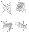
- An amortizing element can be formed by a body with a basically L shape having a horizontal supporting wall and a vertical part that can both be basically flat. But in particular, the element 24 as shown in Fig. 1 , has a horizontal flat wall 25, whereas the vertical wall 26 is corrugated in parallel to the horizontal wall.
- the element 27 in Fig. 2 is analogous to element 24 with the addition of inserts or corner ribs 28 between the horizontal 25 and vertical wall 26.
- the element 29 in Fig. 3 has also an L shape with a flat horizontal supporting wall 30, but with a vertical wall 31 corrugated perpendicularly to the supporting wall.
- the supporting wall 30 can be equipped with protrusions 32 as shown in Figs. 4 and 4a , and/or the vertical wall can be provided with cutting trace marks 33, as shown in Fig. 5 , so as to be able to remove portions and adjust the height according to requirements.
- the corner inserts 28 and/or the protrusions 32 on the horizontal wall of every amortizing element help to compensate the play on the supporting plane of the joined parts, improving in this way its horizontal stability.
- the corrugations, both horizontal and vertical, are provided to give each amortizing element a "spring" effect that helps to compensate lateral play and transversal blocking of the joined parts where each element is inserted between the contact surfaces.
- the amortizing element 55 in Fig. 6 is basically L shaped, but with a step 56 between a flat horizontal section and a corrugated vertical section 58.
- the amortizing element 59 in Fig. 7 has a forked horizontal part 60 and a vertical corrugated part 61.
- the amortizing element 62 in Fig. 8 has, as horizontal wall, an asymmetric U shaped body 63 forming a channel 63, whereas element 64 in Fig. 9 has a basically U shaped body forming a channel 65 and having a shelf-shaped protrusion 66 on one front side.
- each of the L-shaped elements described above can be provided with a thin strip or tongue 71 - Figs. 6-9 - acting as a means for gripping to facilitate handling and positioning the elements for use also having a safety implication, given the fact that it avoids the risk of damage to the operator's fingers. It can be inserted and fixed to the element or an integral part of the latter and have a reduced thickness and/or a tear away section to be removed after the element has been placed in position.
- the amortizing elements according to the invention can be made out of any suitable plastic material, including elastomer, thermoplastics, thermosetting compositions, foamed polymers, silicone in paste or liquid form, with a possible lining and/or overmoulding with inserts or metal net. They can also be provided with an open or closed cell or honeycomb spongy structure. In addition they can be provided with adhesive or dual adhesive bands to facilitate application, in the same way as they may have different colouring in order to visibly recognise the correct destination.
Landscapes
- Engineering & Computer Science (AREA)
- General Engineering & Computer Science (AREA)
- Mechanical Engineering (AREA)
- Chemical & Material Sciences (AREA)
- Combustion & Propulsion (AREA)
- Physics & Mathematics (AREA)
- Acoustics & Sound (AREA)
- Aviation & Aerospace Engineering (AREA)
- Building Environments (AREA)
- Vibration Prevention Devices (AREA)
- Vibration Dampers (AREA)
- Vehicle Interior And Exterior Ornaments, Soundproofing, And Insulation (AREA)
Claims (13)
- Dämpfungselement das zwischen ineinander steckenden Teilen gestellt werden soll, um Stabilität und Schalldichtung der Verbindung durch Vermeiden der Einbaubaufehler und Spiele zu gewährleisten, der durch einen dreidimensionalen Kunststoffkörper gekennzeichnet ist, der dazu strukturiert ist um zumindest einen horizontalen Stützabschnitt und zumindest einen Abschnitt zu bilden, zum Schutz zumindest eines Randgebietes der Kontaktoberflächen zwischen den genannten zu verbindenden Teilen.
- Dämpfungselement nach Anspruch 1, der durch einen grundsätzlich L-geformten Körper mit einer horizontalen Stützwand (25) und einer vertikalen Wand (26) gekennzeichnet ist.
- Dämpfungselement nach Anspruch 2, dadurch gekennzeichnet dass die horizontale Stützwand (25) und die vertikale Wand (26) beide grundsätzlich flach sind.
- Dämpfungselement nach Anspruch 2, dadurch gekennzeichnet dass die genannte horizontale Stützwand (25) flach ist und dass die genannte vertikale Wand (26) parallel zur horizontalen Wand verlaufende Faltungen hat.
- Dämpfungselement nach den Ansprüchen 2 und 3 oder 4, dadurch gekennzeichnet dass zwischen der horizontalen Stützwand und der vertikalen Wand Einsatzstücke oder Eckrippen (28) vorgesehen sind.
- Dämpfungselement nach Anspruch 2, dadurch gekennzeichnet dass die genannte horizontale Wand (30) flach ist und dass die genannte vertikale Wand (31) rechtwinkelig zur horizontalen Wand verlaufende Faltungen hat.
- Dämpfungselement nach Anspruch 6, dadurch gekennzeichnet dass ein Absatz (56) zwischen der horizontalen Wand (57) und der vertikalen Wand (58) vorgesehen ist.
- Dämpfungselement nach Anspruch 6, dadurch gekennzeichnet dass die Grundwand gabelförmig (60) ist.
- Dämpfungselement nach Anspruch 2, dadurch gekennzeichnet dass die genannte horizontale Wand (30) ein Relief (32) hat und dass die genannte vertikale Wand rechtwinkelig zur horizontalen Wand verlaufende Faltungen hat.
- Dämpfungselement nach einem der vorhergehenden Ansprüche, dadurch gekennzeichnet dass zumindest die vertikale Wand mit Schnittzeichen (33) vorgesehen ist, wodurch es möglich ist Teile zu entfernen und die Höhe einzustellen.
- Dämpfungselement nach einem der vorhergehenden Ansprüche, dadurch gekennzeichnet dass der genannte Körper mit einer Zunge oder mit einem Griffstreifen versehen ist, die möglicherweise entfernbar sind.
- Dämpfungselement nach einem der vorhergehenden Ansprüche, dadurch gekennzeichnet dass der genannte Körper mit klebenden oder doppelseitig klebenden Oberflächen versehen werden kann.
- Dämpfungselement nach einem der vorhergehenden Ansprüche, dadurch gekennzeichnet dass der genannte Körper aus einem Kunststoff hergestellt ist, der unter einem Elastomer, Thermoplaste, duroplastiche Verbindungen, geschäumte Polymere und pastenartige oder flüssige Silikone, mit einem eventuellen Belag und/oder Umspritzen mit Einsatzstücken oder mit einem metallischen Netz, ausgewählt ist.
Applications Claiming Priority (2)
| Application Number | Priority Date | Filing Date | Title |
|---|---|---|---|
| IT000005A ITBS20070005A1 (it) | 2007-01-16 | 2007-01-16 | Elemento antivibrante, ammortizzatore e insonoriz zatore |
| PCT/IT2008/000014 WO2008087682A2 (en) | 2007-01-16 | 2008-01-09 | Anti-vibration, shock absorber and sound-proofing element |
Publications (3)
| Publication Number | Publication Date |
|---|---|
| EP2102525A2 EP2102525A2 (de) | 2009-09-23 |
| EP2102525B1 true EP2102525B1 (de) | 2012-10-24 |
| EP2102525B8 EP2102525B8 (de) | 2012-11-28 |
Family
ID=39367126
Family Applications (1)
| Application Number | Title | Priority Date | Filing Date |
|---|---|---|---|
| EP08720184A Active EP2102525B8 (de) | 2007-01-16 | 2008-01-09 | Antivibrations-stossdämpfer und schallschutzelement |
Country Status (4)
| Country | Link |
|---|---|
| EP (1) | EP2102525B8 (de) |
| ES (1) | ES2396597T3 (de) |
| IT (1) | ITBS20070005A1 (de) |
| WO (1) | WO2008087682A2 (de) |
Families Citing this family (1)
| Publication number | Priority date | Publication date | Assignee | Title |
|---|---|---|---|---|
| WO2010066498A2 (de) * | 2008-12-10 | 2010-06-17 | Hettich-Heinze Gmbh & Co. Kg | Antriebsvorrichtung zum motorischen bewegen einer schiebetür und verfahren zum ansteuern der antriebsvorrichtung |
Family Cites Families (2)
| Publication number | Priority date | Publication date | Assignee | Title |
|---|---|---|---|---|
| DE3901898A1 (de) * | 1989-01-23 | 1990-07-26 | Wolf Woco & Co Franz J | Flaechenlager und verfahren zu seiner herstellung |
| US5725931A (en) * | 1995-11-03 | 1998-03-10 | Minnesota Mining And Manufacturing Company | Constrained layer damper with slit(s) and/or cutout(s) |
-
2007
- 2007-01-16 IT IT000005A patent/ITBS20070005A1/it unknown
-
2008
- 2008-01-09 EP EP08720184A patent/EP2102525B8/de active Active
- 2008-01-09 ES ES08720184T patent/ES2396597T3/es active Active
- 2008-01-09 WO PCT/IT2008/000014 patent/WO2008087682A2/en not_active Ceased
Also Published As
| Publication number | Publication date |
|---|---|
| ES2396597T3 (es) | 2013-02-22 |
| EP2102525B8 (de) | 2012-11-28 |
| ITBS20070005A1 (it) | 2008-07-17 |
| EP2102525A2 (de) | 2009-09-23 |
| WO2008087682A2 (en) | 2008-07-24 |
| WO2008087682A3 (en) | 2009-04-02 |
Similar Documents
| Publication | Publication Date | Title |
|---|---|---|
| EP1833665B1 (de) | Kunststoffplatte | |
| EP2102525B1 (de) | Antivibrations-stossdämpfer und schallschutzelement | |
| ES2314807T3 (es) | Elemento de union. | |
| US20180118128A1 (en) | Lid assemblies for storage containers including vibration damping substrates | |
| AU2007312332B2 (en) | Structure for vehicle front face | |
| KR101970310B1 (ko) | 바닥패널 및 이를 구비한 바닥구조체 | |
| CN210912626U (zh) | 一种前舱盖 | |
| JP4246896B2 (ja) | 天井見切縁 | |
| JP4809172B2 (ja) | 発泡充填具、及びそれを用いた発泡体の充填方法 | |
| KR100862476B1 (ko) | 자동차 도어의 임팩트 패드 | |
| JP4324945B2 (ja) | 板状部材の縁部保護材 | |
| CN212462970U (zh) | 一种使用于汽车电机上的吸音包 | |
| EP2073293A1 (de) | Schutzmantel | |
| JP5021401B2 (ja) | ルーフ衝撃吸収構造 | |
| CN210688670U (zh) | 空调器的面板组件以及空调器 | |
| JP4489533B2 (ja) | 梱包用緩衝装置 | |
| KR20180000624U (ko) | 복공판용 상하 방진 장치 | |
| CN217865859U (zh) | 一种护角及门板 | |
| KR102801441B1 (ko) | 선박용 구조물 고정부재 | |
| KR200380136Y1 (ko) | 보호커버가 구비된 콘크리트 성형물 | |
| JP3586891B2 (ja) | ドアミラーブラケット | |
| JPH0315489Y2 (de) | ||
| JP6014840B2 (ja) | 薄板用緩衝材 | |
| JP5756347B2 (ja) | 出隅構造 | |
| JP2019049307A (ja) | 防振装置 |
Legal Events
| Date | Code | Title | Description |
|---|---|---|---|
| PUAI | Public reference made under article 153(3) epc to a published international application that has entered the european phase |
Free format text: ORIGINAL CODE: 0009012 |
|
| 17P | Request for examination filed |
Effective date: 20090618 |
|
| AK | Designated contracting states |
Kind code of ref document: A2 Designated state(s): AT BE BG CH CY CZ DE DK EE ES FI FR GB GR HR HU IE IS IT LI LT LU LV MC MT NL NO PL PT RO SE SI SK TR |
|
| RIN1 | Information on inventor provided before grant (corrected) |
Inventor name: PAPARO, GIOVANNI Inventor name: PAPARO, SAMUELE |
|
| DAX | Request for extension of the european patent (deleted) | ||
| 17Q | First examination report despatched |
Effective date: 20110503 |
|
| REG | Reference to a national code |
Ref country code: DE Ref legal event code: R079 Ref document number: 602008019591 Country of ref document: DE Free format text: PREVIOUS MAIN CLASS: F16F0001373000 Ipc: F16F0001376000 |
|
| RIC1 | Information provided on ipc code assigned before grant |
Ipc: F16F 1/376 20060101AFI20120426BHEP Ipc: F16F 15/08 20060101ALI20120426BHEP Ipc: F16F 1/373 20060101ALI20120426BHEP |
|
| GRAP | Despatch of communication of intention to grant a patent |
Free format text: ORIGINAL CODE: EPIDOSNIGR1 |
|
| GRAS | Grant fee paid |
Free format text: ORIGINAL CODE: EPIDOSNIGR3 |
|
| GRAA | (expected) grant |
Free format text: ORIGINAL CODE: 0009210 |
|
| AK | Designated contracting states |
Kind code of ref document: B1 Designated state(s): AT BE BG CH CY CZ DE DK EE ES FI FR GB GR HR HU IE IS IT LI LT LU LV MC MT NL NO PL PT RO SE SI SK TR |
|
| REG | Reference to a national code |
Ref country code: GB Ref legal event code: FG4D |
|
| REG | Reference to a national code |
Ref country code: CH Ref legal event code: EP |
|
| RAP2 | Party data changed (patent owner data changed or rights of a patent transferred) |
Owner name: G. & G. S.R.L. |
|
| REG | Reference to a national code |
Ref country code: AT Ref legal event code: REF Ref document number: 581121 Country of ref document: AT Kind code of ref document: T Effective date: 20121115 |
|
| REG | Reference to a national code |
Ref country code: IE Ref legal event code: FG4D |
|
| REG | Reference to a national code |
Ref country code: DE Ref legal event code: R096 Ref document number: 602008019591 Country of ref document: DE Effective date: 20121220 |
|
| REG | Reference to a national code |
Ref country code: NO Ref legal event code: T2 Effective date: 20121024 |
|
| REG | Reference to a national code |
Ref country code: ES Ref legal event code: FG2A Ref document number: 2396597 Country of ref document: ES Kind code of ref document: T3 Effective date: 20130222 |
|
| REG | Reference to a national code |
Ref country code: NL Ref legal event code: VDEP Effective date: 20121024 |
|
| PG25 | Lapsed in a contracting state [announced via postgrant information from national office to epo] |
Ref country code: SE Free format text: LAPSE BECAUSE OF FAILURE TO SUBMIT A TRANSLATION OF THE DESCRIPTION OR TO PAY THE FEE WITHIN THE PRESCRIBED TIME-LIMIT Effective date: 20121024 Ref country code: IS Free format text: LAPSE BECAUSE OF FAILURE TO SUBMIT A TRANSLATION OF THE DESCRIPTION OR TO PAY THE FEE WITHIN THE PRESCRIBED TIME-LIMIT Effective date: 20130224 Ref country code: FI Free format text: LAPSE BECAUSE OF FAILURE TO SUBMIT A TRANSLATION OF THE DESCRIPTION OR TO PAY THE FEE WITHIN THE PRESCRIBED TIME-LIMIT Effective date: 20121024 Ref country code: HR Free format text: LAPSE BECAUSE OF FAILURE TO SUBMIT A TRANSLATION OF THE DESCRIPTION OR TO PAY THE FEE WITHIN THE PRESCRIBED TIME-LIMIT Effective date: 20121024 Ref country code: NL Free format text: LAPSE BECAUSE OF FAILURE TO SUBMIT A TRANSLATION OF THE DESCRIPTION OR TO PAY THE FEE WITHIN THE PRESCRIBED TIME-LIMIT Effective date: 20121024 |
|
| PG25 | Lapsed in a contracting state [announced via postgrant information from national office to epo] |
Ref country code: CY Free format text: LAPSE BECAUSE OF FAILURE TO SUBMIT A TRANSLATION OF THE DESCRIPTION OR TO PAY THE FEE WITHIN THE PRESCRIBED TIME-LIMIT Effective date: 20121024 Ref country code: PL Free format text: LAPSE BECAUSE OF FAILURE TO SUBMIT A TRANSLATION OF THE DESCRIPTION OR TO PAY THE FEE WITHIN THE PRESCRIBED TIME-LIMIT Effective date: 20121024 Ref country code: SI Free format text: LAPSE BECAUSE OF FAILURE TO SUBMIT A TRANSLATION OF THE DESCRIPTION OR TO PAY THE FEE WITHIN THE PRESCRIBED TIME-LIMIT Effective date: 20121024 Ref country code: GR Free format text: LAPSE BECAUSE OF FAILURE TO SUBMIT A TRANSLATION OF THE DESCRIPTION OR TO PAY THE FEE WITHIN THE PRESCRIBED TIME-LIMIT Effective date: 20130125 Ref country code: PT Free format text: LAPSE BECAUSE OF FAILURE TO SUBMIT A TRANSLATION OF THE DESCRIPTION OR TO PAY THE FEE WITHIN THE PRESCRIBED TIME-LIMIT Effective date: 20130225 Ref country code: LV Free format text: LAPSE BECAUSE OF FAILURE TO SUBMIT A TRANSLATION OF THE DESCRIPTION OR TO PAY THE FEE WITHIN THE PRESCRIBED TIME-LIMIT Effective date: 20121024 |
|
| PG25 | Lapsed in a contracting state [announced via postgrant information from national office to epo] |
Ref country code: SK Free format text: LAPSE BECAUSE OF FAILURE TO SUBMIT A TRANSLATION OF THE DESCRIPTION OR TO PAY THE FEE WITHIN THE PRESCRIBED TIME-LIMIT Effective date: 20121024 Ref country code: CZ Free format text: LAPSE BECAUSE OF FAILURE TO SUBMIT A TRANSLATION OF THE DESCRIPTION OR TO PAY THE FEE WITHIN THE PRESCRIBED TIME-LIMIT Effective date: 20121024 Ref country code: DK Free format text: LAPSE BECAUSE OF FAILURE TO SUBMIT A TRANSLATION OF THE DESCRIPTION OR TO PAY THE FEE WITHIN THE PRESCRIBED TIME-LIMIT Effective date: 20121024 Ref country code: BG Free format text: LAPSE BECAUSE OF FAILURE TO SUBMIT A TRANSLATION OF THE DESCRIPTION OR TO PAY THE FEE WITHIN THE PRESCRIBED TIME-LIMIT Effective date: 20130124 Ref country code: EE Free format text: LAPSE BECAUSE OF FAILURE TO SUBMIT A TRANSLATION OF THE DESCRIPTION OR TO PAY THE FEE WITHIN THE PRESCRIBED TIME-LIMIT Effective date: 20121024 |
|
| PG25 | Lapsed in a contracting state [announced via postgrant information from national office to epo] |
Ref country code: RO Free format text: LAPSE BECAUSE OF FAILURE TO SUBMIT A TRANSLATION OF THE DESCRIPTION OR TO PAY THE FEE WITHIN THE PRESCRIBED TIME-LIMIT Effective date: 20121024 |
|
| PLBE | No opposition filed within time limit |
Free format text: ORIGINAL CODE: 0009261 |
|
| STAA | Information on the status of an ep patent application or granted ep patent |
Free format text: STATUS: NO OPPOSITION FILED WITHIN TIME LIMIT |
|
| 26N | No opposition filed |
Effective date: 20130725 |
|
| REG | Reference to a national code |
Ref country code: IE Ref legal event code: MM4A |
|
| REG | Reference to a national code |
Ref country code: DE Ref legal event code: R097 Ref document number: 602008019591 Country of ref document: DE Effective date: 20130725 |
|
| PG25 | Lapsed in a contracting state [announced via postgrant information from national office to epo] |
Ref country code: IE Free format text: LAPSE BECAUSE OF NON-PAYMENT OF DUE FEES Effective date: 20130109 |
|
| PGFP | Annual fee paid to national office [announced via postgrant information from national office to epo] |
Ref country code: MC Payment date: 20131230 Year of fee payment: 7 Ref country code: GB Payment date: 20131227 Year of fee payment: 7 |
|
| PGFP | Annual fee paid to national office [announced via postgrant information from national office to epo] |
Ref country code: LU Payment date: 20140211 Year of fee payment: 7 |
|
| PGFP | Annual fee paid to national office [announced via postgrant information from national office to epo] |
Ref country code: NO Payment date: 20131227 Year of fee payment: 7 Ref country code: CH Payment date: 20140127 Year of fee payment: 7 Ref country code: BE Payment date: 20140127 Year of fee payment: 7 Ref country code: DE Payment date: 20140131 Year of fee payment: 7 |
|
| PGFP | Annual fee paid to national office [announced via postgrant information from national office to epo] |
Ref country code: FR Payment date: 20131223 Year of fee payment: 7 Ref country code: AT Payment date: 20131227 Year of fee payment: 7 Ref country code: ES Payment date: 20140122 Year of fee payment: 7 Ref country code: TR Payment date: 20140108 Year of fee payment: 7 |
|
| PG25 | Lapsed in a contracting state [announced via postgrant information from national office to epo] |
Ref country code: MT Free format text: LAPSE BECAUSE OF FAILURE TO SUBMIT A TRANSLATION OF THE DESCRIPTION OR TO PAY THE FEE WITHIN THE PRESCRIBED TIME-LIMIT Effective date: 20121024 Ref country code: LT Free format text: LAPSE BECAUSE OF FAILURE TO SUBMIT A TRANSLATION OF THE DESCRIPTION OR TO PAY THE FEE WITHIN THE PRESCRIBED TIME-LIMIT Effective date: 20121024 |
|
| PG25 | Lapsed in a contracting state [announced via postgrant information from national office to epo] |
Ref country code: BE Free format text: LAPSE BECAUSE OF NON-PAYMENT OF DUE FEES Effective date: 20150131 |
|
| PG25 | Lapsed in a contracting state [announced via postgrant information from national office to epo] |
Ref country code: HU Free format text: LAPSE BECAUSE OF FAILURE TO SUBMIT A TRANSLATION OF THE DESCRIPTION OR TO PAY THE FEE WITHIN THE PRESCRIBED TIME-LIMIT; INVALID AB INITIO Effective date: 20080109 |
|
| REG | Reference to a national code |
Ref country code: DE Ref legal event code: R119 Ref document number: 602008019591 Country of ref document: DE |
|
| REG | Reference to a national code |
Ref country code: CH Ref legal event code: PL |
|
| PG25 | Lapsed in a contracting state [announced via postgrant information from national office to epo] |
Ref country code: LU Free format text: LAPSE BECAUSE OF NON-PAYMENT OF DUE FEES Effective date: 20150109 |
|
| REG | Reference to a national code |
Ref country code: AT Ref legal event code: MM01 Ref document number: 581121 Country of ref document: AT Kind code of ref document: T Effective date: 20150109 |
|
| GBPC | Gb: european patent ceased through non-payment of renewal fee |
Effective date: 20150109 |
|
| PG25 | Lapsed in a contracting state [announced via postgrant information from national office to epo] |
Ref country code: MC Free format text: LAPSE BECAUSE OF NON-PAYMENT OF DUE FEES Effective date: 20150202 |
|
| PG25 | Lapsed in a contracting state [announced via postgrant information from national office to epo] |
Ref country code: CH Free format text: LAPSE BECAUSE OF NON-PAYMENT OF DUE FEES Effective date: 20150131 Ref country code: NO Free format text: LAPSE BECAUSE OF NON-PAYMENT OF DUE FEES Effective date: 20150131 Ref country code: GB Free format text: LAPSE BECAUSE OF NON-PAYMENT OF DUE FEES Effective date: 20150109 Ref country code: DE Free format text: LAPSE BECAUSE OF NON-PAYMENT OF DUE FEES Effective date: 20150801 Ref country code: LI Free format text: LAPSE BECAUSE OF NON-PAYMENT OF DUE FEES Effective date: 20150131 |
|
| REG | Reference to a national code |
Ref country code: FR Ref legal event code: ST Effective date: 20150930 |
|
| PG25 | Lapsed in a contracting state [announced via postgrant information from national office to epo] |
Ref country code: AT Free format text: LAPSE BECAUSE OF NON-PAYMENT OF DUE FEES Effective date: 20150109 Ref country code: FR Free format text: LAPSE BECAUSE OF NON-PAYMENT OF DUE FEES Effective date: 20150202 |
|
| REG | Reference to a national code |
Ref country code: ES Ref legal event code: FD2A Effective date: 20160226 |
|
| PG25 | Lapsed in a contracting state [announced via postgrant information from national office to epo] |
Ref country code: ES Free format text: LAPSE BECAUSE OF NON-PAYMENT OF DUE FEES Effective date: 20150110 |
|
| PG25 | Lapsed in a contracting state [announced via postgrant information from national office to epo] |
Ref country code: TR Free format text: LAPSE BECAUSE OF NON-PAYMENT OF DUE FEES Effective date: 20150109 |
|
| P01 | Opt-out of the competence of the unified patent court (upc) registered |
Effective date: 20230321 |
|
| PGFP | Annual fee paid to national office [announced via postgrant information from national office to epo] |
Ref country code: IT Payment date: 20250115 Year of fee payment: 18 |