EP2102039B1 - Scheibenwischvorrichtung, insbesondere für ein kraftfahrzeug - Google Patents
Scheibenwischvorrichtung, insbesondere für ein kraftfahrzeug Download PDFInfo
- Publication number
- EP2102039B1 EP2102039B1 EP07822661A EP07822661A EP2102039B1 EP 2102039 B1 EP2102039 B1 EP 2102039B1 EP 07822661 A EP07822661 A EP 07822661A EP 07822661 A EP07822661 A EP 07822661A EP 2102039 B1 EP2102039 B1 EP 2102039B1
- Authority
- EP
- European Patent Office
- Prior art keywords
- holder
- carrier
- section
- wiping device
- windscreen wiping
- Prior art date
- Legal status (The legal status is an assumption and is not a legal conclusion. Google has not performed a legal analysis and makes no representation as to the accuracy of the status listed.)
- Not-in-force
Links
- 230000000295 complement effect Effects 0.000 claims description 4
- 238000010079 rubber tapping Methods 0.000 claims description 3
- 238000009434 installation Methods 0.000 description 2
- 239000002184 metal Substances 0.000 description 2
- 210000000988 bone and bone Anatomy 0.000 description 1
- 230000001419 dependent effect Effects 0.000 description 1
- 238000004519 manufacturing process Methods 0.000 description 1
Images
Classifications
-
- B—PERFORMING OPERATIONS; TRANSPORTING
- B60—VEHICLES IN GENERAL
- B60S—SERVICING, CLEANING, REPAIRING, SUPPORTING, LIFTING, OR MANOEUVRING OF VEHICLES, NOT OTHERWISE PROVIDED FOR
- B60S1/00—Cleaning of vehicles
- B60S1/02—Cleaning windscreens, windows or optical devices
- B60S1/04—Wipers or the like, e.g. scrapers
-
- B—PERFORMING OPERATIONS; TRANSPORTING
- B60—VEHICLES IN GENERAL
- B60S—SERVICING, CLEANING, REPAIRING, SUPPORTING, LIFTING, OR MANOEUVRING OF VEHICLES, NOT OTHERWISE PROVIDED FOR
- B60S1/00—Cleaning of vehicles
- B60S1/02—Cleaning windscreens, windows or optical devices
- B60S1/04—Wipers or the like, e.g. scrapers
- B60S1/0413—Modular wiper assembly
- B60S1/0422—Modular wiper assembly having a separate transverse element
- B60S1/0427—Modular wiper assembly having a separate transverse element characterised by the attachment of the wiper motor holder to the transverse element
-
- B—PERFORMING OPERATIONS; TRANSPORTING
- B60—VEHICLES IN GENERAL
- B60S—SERVICING, CLEANING, REPAIRING, SUPPORTING, LIFTING, OR MANOEUVRING OF VEHICLES, NOT OTHERWISE PROVIDED FOR
- B60S1/00—Cleaning of vehicles
- B60S1/02—Cleaning windscreens, windows or optical devices
- B60S1/04—Wipers or the like, e.g. scrapers
- B60S1/32—Wipers or the like, e.g. scrapers characterised by constructional features of wiper blade arms or blades
-
- B—PERFORMING OPERATIONS; TRANSPORTING
- B60—VEHICLES IN GENERAL
- B60S—SERVICING, CLEANING, REPAIRING, SUPPORTING, LIFTING, OR MANOEUVRING OF VEHICLES, NOT OTHERWISE PROVIDED FOR
- B60S1/00—Cleaning of vehicles
- B60S1/02—Cleaning windscreens, windows or optical devices
- B60S1/04—Wipers or the like, e.g. scrapers
- B60S1/0413—Modular wiper assembly
- B60S1/0422—Modular wiper assembly having a separate transverse element
-
- B—PERFORMING OPERATIONS; TRANSPORTING
- B60—VEHICLES IN GENERAL
- B60S—SERVICING, CLEANING, REPAIRING, SUPPORTING, LIFTING, OR MANOEUVRING OF VEHICLES, NOT OTHERWISE PROVIDED FOR
- B60S1/00—Cleaning of vehicles
- B60S1/02—Cleaning windscreens, windows or optical devices
- B60S1/04—Wipers or the like, e.g. scrapers
- B60S1/0413—Modular wiper assembly
- B60S1/0422—Modular wiper assembly having a separate transverse element
- B60S1/0425—Modular wiper assembly having a separate transverse element characterised by the attachment of the wiper shaft holders to the transverse element
Definitions
- the invention relates to a windshield wiper device, in particular for a motor vehicle, according to the preamble of the independent claim.
- windscreen wiper devices for motor vehicles which have a substantially tubular support to which a drive device is fastened by a holder which is formed on a housing of the drive device. Furthermore, it is known to provide the carrier with a separate holder, for example a mounting plate, to which the drive device is attached.
- a windshield wiper device is known in which a tubular support is pressed in its central portion to a U-shaped cross-sectional profile.
- the drive device is in this case arranged in a housing which has a holder which is fastened in this U-shaped cross-sectional area.
- the windshield wiper device according to the invention with the features of the main claim has the advantage that the carrier, for attachment to the holder, at least one, in cross-section substantially H-shaped portion. In this way, results in a more stable and torsionally rigid windshield wiper device, which is also much cheaper, and easier to manufacture.
- the H-shaped section has side legs and a central section connecting the side legs, which is at least partially hollow in its interior. In this way results in a much higher stability and rigidity of the carrier and thus the entire windshield wiper device.
- the stability of the windshield wiper device can advantageously be increased by the fact that the H-shaped section has side legs and a central section connecting the side legs and at least one of the side legs is at least partially hollow in its interior.
- a fastening element is provided for fastening the carrier to the holder, which is formed by a self-tapping threaded screw.
- the holder in the region of the H-shaped portion has a receptacle for the fastening element, wherein the carrier has a recess which is formed or arranged complementary to the recess in the holder.
- the fasteners are advantageously formed by blind rivets.
- a very high stability results from the fact that the holder is designed as a mounting dome and the carrier is placed in the region of its H-shaped portion on the holder.
- the holder has at least one pin which engages for positioning the wiper motor to the carrier in at least one second recess formed complementary to the carrier.
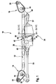
- FIG. 1 a windshield wiper device 10 is shown in a schematic representation.
- the tube can of course also have a square, rectangular or elliptical cross-section. In principle, however, a profile support instead of a pipe is possible.
- a wiper bearing 14, 16 is fixed in each case, in each of which a wiper shaft 18, 20 is mounted.
- the wiper bearings 14, 16 are fixed to the carrier 12, non-positively and / or positively and / or cohesively, for example, crimped, welded, screwed or riveted. Also a snap or clip connection is possible here.
- a fastening section 22, 24 is provided on the wiper bearings 14, 16, which serves for fastening the windshield wiper device 10 to a motor vehicle.
- the wiper shafts 18, 20 are each driven via a drive crank 26, 28 which is non-rotatably connected to the respective wiper shaft 18, 20.
- the wiper shafts 18, 20 perform a pendulum movement, each a push rod 30, 32 is articulated at the free end of the respective drive crank 26, 28, the crank 26, 28 facing away from the end with a driven crank, a drive device 34 is connected. If the output crank of the drive device 34 performs a circular or oscillating movement, then the drive cranks 26, 28 are set in oscillating motion by the push rods 30, 32.
- the drive device 34 is designed here as an electric motor, in which a worm gear is integrated.
- the drive device 34 is enclosed by a housing 36 which has holders 38 which serve to fasten the drive device 34 to the carrier 12.
- the holder 38 are in this case formed as a dome. These can each have a receptacle for receiving fastening elements 40. Self-tapping threaded screws, blind rivets or staples can serve as fastening elements 40.
- the holder 38 is in this case in the central region with respect to the longitudinal extension of the carrier 12, ie between the wiper bearings 14, 16, attached to the carrier 12. For this purpose, the tubular carrier 12 is squeezed together in the region of the holder 38 to form an H-shaped profile, so that the carrier 12 has an H-shaped section 42.
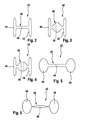
- FIG. 2 a cross-section through the H-shaped portion 42 of the carrier 12 is shown.
- the H-shaped portion in this case has two side legs 44, which are interconnected approximately in the middle of their longitudinal extent by a central portion 46.
- the carrier 12 is made of a sheet metal tube with the thickness D, then the side limb 44 and the central portion 46 have a thickness of about 2 sheet metal layers and thus a thickness of 2 D.
- a recess 48 Approximately in the middle between the two side limbs 44 has the central portion 46 a recess 48, which is designed for example as a circular hole.
- the recess 48 serves to cooperate with the fastening element 40, so that the H-shaped section 42 and thus the support 12 can be connected to the holder 38 of the housing 36.
- FIG. 3 For example, a variation of the substantially H-shaped portion 42 of a windshield wiper device 10 is shown.
- the two side legs 44 are as in FIG. 2 educated.
- the central portion 46 here is diamond-shaped, so that the central portion 46 is hollow in its interior.
- the recess 48 as a receptacle for the fastening element is in this case formed by a bore which extend approximately through the two, the side legs 44 facing away corners of the cross-sectionally diamond-shaped central portion 46.
- the bore can also run obliquely through the two, substantially parallel surfaces of the diamond-shaped central section 46.
- FIG. 4 another variation of the H-shaped portion 42 is shown.
- the two side legs 44 are the same as in the FIGS. 2 and 3 educated.
- the central portion 46 is hereby bent to a circular in cross-section in western form, so that there is a cavity inside.
- the recess 48 is represented by two holes on the side walls, which lie between the side legs 44. This results in an opening on both sides of the central portion 46, through which the fastening element 40 can be threaded through substantially parallel to the side legs 44.
- FIG. 5 another variation of section 42 is shown.
- the H-shaped portion 42 is formed substantially bone-shaped.
- the two side legs 44 are substantially circular and hollow inside. Connected, the two side legs 44 through the central portion 46, which is not completely filled in its interior. This creates a cavity that connects the cavities of the side legs 44 with each other.
- two bores are provided as recesses 48 here, in the central portion, through which the fastener 40 can be threaded.
- FIG. 6 Yet another variation of the H-shaped portion 42 is shown in cross-section.
- the two side legs 44 are also here as in FIG. 5 hollow inside, so that here, too, essentially gives a bone shape.
- the central portion 46 is formed hollow in the area between the two side legs 44, but the terminal portions between the central portion 46 and the respective side legs 44 are squeezed together so that no cavity is provided at this point.
- recesses 48 are provided here, which are formed as holes in the central portion 46.
- FIG. 2 to FIG. 6 is common that they are formed with respect to the side legs 44 and the central portion 46 in cross-section mirror symmetry.
- the recess 48 for receiving the fastening element 40 is arranged substantially centrally between the two side legs 44 and passes through the central portion 46 in full length.
- the fastening element can in each case be received parallel to the side limbs 44.
- FIGS. 5 and 6 which show a substantially bone-shaped configuration of the cross section of the portion 42 are not limited to a circular in cross-section shape of the side legs 44. Rather, the side legs 44 may also be elliptical. Furthermore, it is also possible to completely dispense with the symmetry between the two side legs 44, and provide only one side leg 44.
- a second recess may be provided which does not fully penetrate the central portion 46. This second recess is then arranged to receive a pin which is disposed on the holder 38 of the windshield wiper device 10, so that the H-shaped portion 40 of the support 12 during assembly easier and more accurately positioned. Characterized a positioning aid is shown, which facilitates the installation of the windshield wiper device 10 substantially.
Landscapes
- Engineering & Computer Science (AREA)
- Mechanical Engineering (AREA)
- Body Structure For Vehicles (AREA)
- Connection Of Motors, Electrical Generators, Mechanical Devices, And The Like (AREA)
- Window Of Vehicle (AREA)
- Processing Of Solid Wastes (AREA)
- Motor Or Generator Frames (AREA)
- Moving Of Heads (AREA)
- Transmission Devices (AREA)
Description
- Die Erfindung betrifft eine Scheibenwischvorrichtung, insbesondere für ein Kraftfahrzeug, nach Gattung des unabhängigen Anspruchs.
- Es sind schon zahlreiche Scheibenwischvorrichtungen für Kraftfahrzeuge bekannt, die einen im Wesentlichen rohrförmigen Träger aufweisen, an dem eine Antriebseinrichtung durch einen Halter befestigt ist, der an einem Gehäuse der Antriebseinrichtung ausgebildet ist. Weiterhin ist es bekannt, am Träger einen separaten Halter, beispielsweise ein Befestigungsblech vorzusehen, an dem die Antriebseinrichtung befestigt ist.
- Beispielsweise ist aus der
US-B-6,343,403 eine Scheibenwischvorrichtung bekannt, bei der ein rohrförmiger Träger in seinem Mittelabschnitt zu einem U-förmigen Querschnittsprofil gepresst ist. Die Antriebseinrichtung ist hierbei in einem Gehäuse angeordnet, welches einen Halter aufweist, der in diesem U-förmig gebogenen Querschnittsbereich befestigt ist. - Eine gattungsgemäße Scheibeuwischvorrichtung ist aus der
EP-A-0 430 375 bekannt. - Die erfindungsgemäße Scheibenwischvorrichtung mit den Merkmalen des Hauptanspruchs hat den Vorteil, dass der Träger, zur Befestigung am Halter, zumindest einen, im Querschnitt im Wesentlichen H-förmigen Abschnitt aufweist. Auf diese Weise ergibt sich eine stabilere und torsionssteifere Scheibenwischvorrichtung, die darüber hinaus wesentlich kostengünstiger, sowie einfacher zu fertigen ist.
- Durch die in den Unteransprüchen aufgeführten Maßnahmen ergeben sich vorteilhafte Weiterbildungen und Verbesserungen der im Hauptanspruch angegebenen Merkmale.
- Besonders vorteilhaft ist es, wenn der H-förmige Abschnitt Seitenschenkel und einen die Seitenschenkel verbindenden Zentralabschnitt aufweist, der in seinem Inneren zumindest teilweise hohl ist. Auf diese Weise ergibt sich eine wesentlich höhere Stabilität und Steifigkeit des Trägers und damit der gesamten Scheibenwischvorrichtung.
- Weiterhin kann die Stabilität der Scheibenwischvorrichtung vorteilhafter Weise dadurch erhöht werden, dass der H-förmige Abschnitt Seitenschenkel und einen die Seitenschenkel verbindenden Zentralabschnitt aufweist und zumindest einer der Seitenschenkel in seinem Inneren zumindest teilweise hohl ist.
- Vorteilhaft ist darüber hinaus, wenn ein Befestigungselement zur Befestigung des Trägers am Halter vorgesehen ist, das durch eine selbstschneidende Gewindeschraube gebildet ist.
- In einer besonders vorteilhaften Ausgestaltung weist der Halter im Bereich des H-förmigen Abschnitts eine Aufnahme für das Befestigungselement auf, wobei der Träger eine Aussparung aufweist, die komplementär zu der Aussparung im Halter ausgebildet bzw. angeordnet ist.
- In einer Variation sind die Befestigungselemente vorteilhafter Weise durch Blindniete gebildet.
- Eine sehr hohe Stabilität ergibt sich dadurch, dass der Halter als Befestigungsdom ausgebildet ist und der Träger im Bereich seines H-förmigen Abschnitts auf den Halter aufsetzbar ist.
- Eine besonders leichte Montage der Scheibenwischvorrichtung wird dadurch erzielt, dass der Halter mindestens einen Stift aufweist, der zur Positionierung des Wischermotors zu dem Träger in mindestens eine am Träger komplementär ausgebildete zweite Aussparung eingreift.
- Ein Ausführungsbeispiel der Erfindung ist in den Zeichnungen dargestellt und in der nachfolgenden Beschreibung näher erläutert.
- Es zeigen:
-
Figur 1 , eine erfindungsgemäße Scheibenwischvorrichtung in einer schematischen Darstellung, -
Figur 2 , einen Querschnitt durch den Träger der Scheibenwischvorrichtung und -
Figuren 3 bis 6 , Querschnitte durch einen Träger der Scheibenwischvorrichtung in verschiedenen Variationen. - In
Figur 1 ist eine Scheibenwischvorrichtung 10 in schematischer Darstellung gezeigt. - Diese umfasst im Wesentlichen einen Träger 12, der als Rohr ausgebildet ist. Neben dem hier gezeigten kreisrunden Querschnitt kann das Rohr natürlich auch einen quadratischen, rechteckigen oder elliptischen Querschnitt aufweisen. Grundsätzlich ist jedoch auch ein Profilträger anstatt eines Rohrs möglich.
- An den Enden der Längserstreckung des Trägers 12 ist jeweils ein Wischerlager 14, 16 befestigt, in dem jeweils eine Wischerwelle 18, 20 gelagert ist. Die Wischerlager 14, 16 sind an den Träger 12, kraft- und/oder form- und/oder stoffschlüssig befestigt, beispielsweise angecrimmpt, angeschweißt, angeschraubt oder angenietet. Auch eine oder Schnapp- oder Clipsverbindung ist hier möglich.
- An den Wischerlagern 14, 16 ist darüber hinaus ein Befestigungsabschnitt 22, 24 vorgesehen, der zur Befestigung der Scheibenwischvorrichtung 10 an einem Kraftfahrzeug dient. Die Wischerwellen 18, 20 werden jeweils über eine Antriebskurbel 26, 28, die drehfest mit der jeweiligen Wischerwelle 18, 20 verbunden ist, angetrieben. Damit die Wischerwellen 18, 20 eine pendelnde Bewegung vollführen, ist am freien Ende der jeweiligen Antriebskurbel 26, 28, jeweils eine Schubstange 30, 32 angelenkt, deren der Kurbel 26, 28 abgewandtes Ende mit einer Abtriebskurbel, einer Antriebseinrichtung 34 verbunden ist. Vollführt die Abtriebskurbel der Antriebseinrichtung 34 eine kreisförmige oder pendelnde Bewegung, so werden die Antriebskurbeln 26, 28 durch die Schubstangen 30, 32 in eine pendelnde Bewegung versetzt. Die Antriebseinrichtung 34 ist hier als Elektromotor ausgebildet, in den ein Schneckengetriebe integriert ist. Die Antriebseinrichtung 34 ist von einem Gehäuse 36 umschlossen, welches Halter 38 aufweist, die der Befestigung der Antriebseinrichtung 34 am Träger 12 dienen. Die Halter 38 sind hierbei als Dome ausgebildet. Diese können jeweils eine Aufnahme zur Aufnahme von Befestigungselementen 40 aufweisen. Als Befestigungselemente 40 können hierbei selbstschneidende Gewindeschrauben, Blindniete oder Klammern dienen. Der Halter 38 ist hierbei im mittleren Bereich bezüglich der Längserstreckung des Trägers 12, also zwischen den Wischerlagern 14, 16, am Träger 12 befestigt. Hierzu ist der rohrförmige Träger 12 im Bereich der Halter 38 zu einem H-förmigen Profil zusammengequetscht, so dass der Träger 12 einen H-förmigen Abschnitt 42 aufweist.
- In
Figur 2 ist ein Querschnitt durch den H-förmigen Abschnitt 42 des Trägers 12 gezeigt. Der H-förmige Abschnitt weist hierbei zwei Seitenschenkel 44 auf, die etwa in der Mitte ihrer Längserstreckung durch einen Zentralabschnitt 46 miteinander verbunden sind. Ist der Träger 12 aus einem Blechrohr mit der Dicke D gefertigt, so ergibt sich für die Seitenschenkel 44 und dem Zentralabschnitt 46 eine Dicke von etwa 2 Blechlagen und damit eine Dicke von 2 D. Etwa in der Mitte zwischen den beiden Seitenschenkeln 44 weist der Zentralabschnitt 46 eine Aussparung 48 auf, die beispielsweise als kreisrundes Loch ausgeführt ist. Die Aussparung 48 dient hierbei dem Zusammenwirken mit dem Befestigungselement 40, so dass der H-förmige Abschnitt 42 und damit der Träger 12 mit dem Halter 38 des Gehäuses 36 verbunden werden kann. - In
Figur 3 ist eine Variation des im Wesentlichen H-förmigen Abschnitts 42 einer Scheibenwischvorrichtung 10 gezeigt. Die beiden Seitenschenkel 44 sind wie inFigur 2 ausgebildet. Der Zentralabschnitt 46 jedoch ist hierbei rautenförmig ausgebildet, so dass der Zentralabschnitt 46 in seinem Inneren hohl ausgebildet ist. Die Aussparung 48 als Aufnahme für das Befestigungselement ist hierbei durch eine Bohrung gebildet, die etwa durch die beiden, den Seitenschenkeln 44 abgewandten Ecken des im Querschnitt rautenförmigen Zentralabschnitts 46 verlaufen. In einer Variation kann die Bohrung aber auch durch die beiden, im Wesentlichen parallel verlaufenden Flächen des rautenförmigen Zentralabschnitts 46, mithin also schräg verlaufen. - In
Figur 4 ist eine weitere Variation des H-förmigen Abschnitts 42 gezeigt. Die beiden Seitenschenkel 44 sind hierbei gleich wie in denFiguren 2 und 3 ausgebildet. Der Zentralabschnitt 46 jedoch ist hierbei zu einer im Querschnitt im Westentlichen kreisrunden Form gebogen, so dass sich im Inneren ein Hohlraum ergibt. Die Aussparung 48 wird durch zwei Bohrungen an den Seitenwänden dargestellt, die zwischen den Seitenschenkeln 44 liegen. Dadurch ergibt sich auf beiden Seiten des Zentralabschnitts 46 eine Öffnung, durch die das Befestigungselement 40 im Wesentlichen parallel zu den Seitenschenkeln 44 durchgefädelt werden kann. - In
Figur 5 ist eine weitere Variation des Abschnitts 42 gezeigt. Hierbei ist der H-förmige Abschnitt 42 im Wesentlichen knochenförmig ausgebildet. Die beiden Seitenschenkel 44 sind im Wesentlichen kreisrund und innen hohl ausgebildet. Verbunden sind die beiden Seitenschenkel 44 durch den Zentralabschnitt 46, der in seinem Inneren jedoch nicht zur Gänze ausgefüllt ist. Dadurch entsteht ein Hohlraum, der die Hohlräume der Seitenschenkel 44 miteinander verbindet. Zur Aufnahme des Befestigungselementes sind auch hier im Zentralabschnitt 46 zwei Bohrungen als Aussparungen 48 vorgesehen, durch die das Befestigungselement 40 gefädelt werden kann. - In
Figur 6 ist noch eine weitere Variation des H-förmigen Abschnitts 42 im Querschnitt dargestellt. Die beiden Seitenschenkel 44 sind hier ebenfalls wie im inFigur 5 gezeigten Beispiel innen hohl, so dass sich auch hier im Wesentlichen eine Knochenform ergibt. Der Zentralabschnitt 46 ist im Bereich zwischen den beiden Seitenschenkeln 44 hohl ausgebildet, jedoch sind die Anschlussbereiche zwischen dem Zentralabschnitt 46 und dem jeweiligen Seitenschenkel 44 derart zusammengequetscht, so dass an dieser Stelle kein Hohlraum vorgesehen ist. Zur Aufnahme des Befestigungselementes 40 sind auch hier Aussparungen 48 vorgesehen, die als Bohrungen im Zentralabschnitt 46 ausgebildet sind. - All diesen Ausführungsbeispielen aus
Figur 2 bis Figur 6 ist gemein, dass diese bezüglich der Seitenschenkel 44 und des Zentralabschnitts 46 im Querschnitt spiegelsymmetrisch ausgebildet sind. Die Aussparung 48 zur Aufnahme des Befestigungselementes 40 ist dabei im Wesentlichen mittig zwischen den beiden Seitenschenkeln 44 angeordnet und durchgreift den Zentralabschnitt 46 in voller Länge. Das Befestigungselement kann dabei jeweils parallel zu den Seitenschenkeln 44 aufgenommen werden. - Die Ausführungsbeispiele in
Figuren 5 und 6 , die eine im Wesentlichen knochenförmige Ausbildung des Querschnitts des Abschnitts 42 zeigen, sind nicht auf eine im Querschnitt kreisrunde Form der Seitenschenkel 44 beschränkt. Vielmehr können die Seitenschenkel 44 auch elliptisch ausgebildet sein. Weiterhin ist es auch möglich, völlig auf die Symmetrie zwischen den beiden Seitenschenkeln 44 zu verzichten, und nur einen Seitenschenkel 44 vorzusehen. - Weiterhin kann im Zentralabschnitt 46 auch eine zweite Aussparung vorgesehen sein, die den Zentralabschnitt 46 nicht vollständig durchgreift. Diese zweite Aussparung ist dann so angeordnet, dass sie einen Stift aufzunehmen vermag, der am Halter 38 der Scheibenwischvorrichtung 10 angeordnet ist, so dass der H-förmige Abschnitt 40 des Trägers 12 bei der Montage einfacher und exakter positioniert werden kann. Dadurch wird eine Positionierhilfe dargestellt, die die Montage der Scheibenwischvorrichtung 10 wesentlich erleichtert.
Claims (7)
- Scheibenwischvorrichtung (10), insbesondere für ein Kraftfahrzeug, mit einem Träger (12), der insbesondere im wesentlichen rohrförmig ausgebildet ist, einer Antriebseinrichtung (34) und einem Halter (38), der an einem Gehäuse (36) der Antriebseinrichtung (34) ausgebildet ist,
dadurch gekennzeichnet, daß
der Träger (12) zur Befestigung am Halter (38) zumindest einen im Querschnitt im wesentlichen H-förmigen Abschnitt (42) aufweist. - Scheibenwischvorrichtung (10) nach Anspruch 1, dadurch gekennzeichnet, daß der H-förmige Abschnitt (42) Seitenschenkel (44) und einen, die Seitenschenkel (44) verbindenden Zentralabschnitt (46) aufweist, und der Zentralabschnitt (46) und/oder zumindest einer er Seitenschenkel (44) in ihrem Inneren zumindest teilweise hohl ausgebildet sind.
- Scheibenwischvorrichtung (10) nach einem der vorhergehenden Ansprüche, dadurch gekennzeichnet, dass mindestens ein Befestigungselement (40) zur Befestigung des Trägers (12) am Halter (38) vorgesehen ist, das durch eine selbstschneidende Gewindeschraube gebildet ist.
- Scheibenwischvorrichtung (10) nach einem der vorhergehenden Ansprüche, dadurch gekennzeichnet, daß der Halter (38), insbesondere im Bereich des H-förmigen Abschnitts (42), mindestens eine Aufnahme für ein Befestigungselement (40) umfasst, wobei der Träger (12) mindestens eine Aussparung (48) aufweist, die komplementär zu der mindestens einen in dem Halter (38) ausgebildet ist.
- Scheibenwischvorrichtung (10) nach Anspruch 4, dadurch gekennzeichnet, dass das mindestens eine Befestigungselement (40) durch einen Blindniet gebildet ist.
- Scheibenwischvorrichtung (10) nach einem der vorhergehenden Ansprüche, dadurch gekennzeichnet, daß der Halter (38) als Befestigungsdom ausgebildet ist und der Träger (12) im Bereich seines H-förmigen Abschnitts (42) auf den Halter (38) aufsetzbar ist.
- Scheibenwischvorrichtung (10) nach einem der vorhergehenden Ansprüche, dadurch gekennzeichnet, dass der Halter (38) mindestens einen Stift aufweist, der zur Positionierung der Antriebseinrichtung (34) zu dem Träger (12) in mindestens eine am Träger (12) komplementär ausgebildete zweite Aussparung eingreift.
Priority Applications (1)
| Application Number | Priority Date | Filing Date | Title |
|---|---|---|---|
| PL07822661T PL2102039T3 (pl) | 2006-12-12 | 2007-11-16 | Mechanizm wycieraczek szyby, zwłaszcza dla pojazdu mechanicznego |
Applications Claiming Priority (2)
| Application Number | Priority Date | Filing Date | Title |
|---|---|---|---|
| DE102006058740A DE102006058740A1 (de) | 2006-12-12 | 2006-12-12 | Scheibenwischvorrichtung, insbesondere für ein Kraftfahrzeug |
| PCT/EP2007/062441 WO2008071515A1 (de) | 2006-12-12 | 2007-11-16 | Scheibenwischvorrichtung, insbesondere für ein kraftfahrzeug |
Publications (2)
| Publication Number | Publication Date |
|---|---|
| EP2102039A1 EP2102039A1 (de) | 2009-09-23 |
| EP2102039B1 true EP2102039B1 (de) | 2011-04-20 |
Family
ID=38973617
Family Applications (1)
| Application Number | Title | Priority Date | Filing Date |
|---|---|---|---|
| EP07822661A Not-in-force EP2102039B1 (de) | 2006-12-12 | 2007-11-16 | Scheibenwischvorrichtung, insbesondere für ein kraftfahrzeug |
Country Status (10)
| Country | Link |
|---|---|
| US (1) | US20090271939A1 (de) |
| EP (1) | EP2102039B1 (de) |
| JP (1) | JP2010512276A (de) |
| KR (1) | KR20090087911A (de) |
| CN (1) | CN101557965B (de) |
| AT (1) | ATE506229T1 (de) |
| DE (2) | DE102006058740A1 (de) |
| ES (1) | ES2361929T3 (de) |
| PL (1) | PL2102039T3 (de) |
| WO (1) | WO2008071515A1 (de) |
Families Citing this family (6)
| Publication number | Priority date | Publication date | Assignee | Title |
|---|---|---|---|---|
| DE102007058537A1 (de) * | 2007-12-06 | 2009-06-10 | Robert Bosch Gmbh | Scheibenwischvorrichtung für ein Kraftfahrzeug |
| DE102007061721A1 (de) | 2007-12-20 | 2009-06-25 | Robert Bosch Gmbh | Wischanlage für ein Kraftfahrzeug |
| DE102009057589B4 (de) * | 2008-12-11 | 2017-02-02 | Asmo Co., Ltd. | Wischervorrichtung |
| DE102009002958A1 (de) * | 2009-05-08 | 2010-11-11 | Robert Bosch Gmbh | Scheibenwisch-Gestängeeinrichtung, Herstellungsverfahren dafür sowie Scheibenwischvorrichtung |
| DE102010029105B4 (de) * | 2009-10-21 | 2018-01-11 | Robert Bosch Gmbh | Scheibenwischervorrichtung |
| DE102015215544A1 (de) * | 2015-08-14 | 2017-02-16 | Robert Bosch Gmbh | Wischeranlage |
Family Cites Families (5)
| Publication number | Priority date | Publication date | Assignee | Title |
|---|---|---|---|---|
| US5074613A (en) * | 1989-12-01 | 1991-12-24 | General Motors Corporation | Vehicle windshield wiper system with improved housing to frame connection |
| CA2118874C (en) * | 1993-03-12 | 2001-05-29 | Tadao Kushida | Vehicle windshield wiper blade assembly and wiper system |
| DE4421878B4 (de) * | 1994-06-23 | 2007-09-27 | Valeo Wischersysteme Gmbh | Schwingungsdämpfende Befestigung einer Scheibenwischerantriebseinrichtung |
| US6343403B1 (en) * | 1998-07-24 | 2002-02-05 | Asmo Co., Ltd. | Wiper device, and method of manufacturing hollow frame for wiper device |
| US6434403B1 (en) * | 1999-02-19 | 2002-08-13 | Bodycom, Inc. | Personal digital assistant with wireless telephone |
-
2006
- 2006-12-12 DE DE102006058740A patent/DE102006058740A1/de not_active Withdrawn
-
2007
- 2007-11-16 JP JP2009540688A patent/JP2010512276A/ja not_active Withdrawn
- 2007-11-16 WO PCT/EP2007/062441 patent/WO2008071515A1/de not_active Ceased
- 2007-11-16 CN CN2007800458060A patent/CN101557965B/zh not_active Expired - Fee Related
- 2007-11-16 DE DE502007007027T patent/DE502007007027D1/de active Active
- 2007-11-16 ES ES07822661T patent/ES2361929T3/es active Active
- 2007-11-16 AT AT07822661T patent/ATE506229T1/de active
- 2007-11-16 EP EP07822661A patent/EP2102039B1/de not_active Not-in-force
- 2007-11-16 PL PL07822661T patent/PL2102039T3/pl unknown
- 2007-11-16 KR KR1020097012049A patent/KR20090087911A/ko not_active Ceased
- 2007-11-16 US US12/305,248 patent/US20090271939A1/en not_active Abandoned
Also Published As
| Publication number | Publication date |
|---|---|
| ATE506229T1 (de) | 2011-05-15 |
| JP2010512276A (ja) | 2010-04-22 |
| DE102006058740A1 (de) | 2008-06-19 |
| ES2361929T3 (es) | 2011-06-24 |
| DE502007007027D1 (de) | 2011-06-01 |
| PL2102039T3 (pl) | 2011-09-30 |
| WO2008071515A1 (de) | 2008-06-19 |
| EP2102039A1 (de) | 2009-09-23 |
| CN101557965A (zh) | 2009-10-14 |
| US20090271939A1 (en) | 2009-11-05 |
| CN101557965B (zh) | 2013-12-18 |
| KR20090087911A (ko) | 2009-08-18 |
Similar Documents
| Publication | Publication Date | Title |
|---|---|---|
| EP0918671B1 (de) | Elektrische antriebseinheit | |
| WO2008071515A1 (de) | Scheibenwischvorrichtung, insbesondere für ein kraftfahrzeug | |
| EP2032401B1 (de) | Scheibenwischvorrichtung, insbesondere für ein kraftfahrzeug | |
| WO2008009683A1 (de) | Anordnung zur befestigung einer lenksäule eines kraftfahrzeuges | |
| EP1735193B1 (de) | Scheibenwischvorrichtung, insbesondere für ein kraftfahrzeug | |
| EP2323875B1 (de) | Scheibenwischerantrieb | |
| EP2177404A1 (de) | Scheibenwischerarm | |
| EP1547880A1 (de) | Scheibenwischvorrichtung, insbesondere für ein Kraftfahrzeug | |
| EP2237997B1 (de) | Befestigungsrohr sowie wischanlage | |
| DE10045806B4 (de) | Sitzlängsverstellung für einen Kraftfahrzeugsitz | |
| DE10259956B4 (de) | Scheibenwischvorrichtung, insbesondere für ein Kraftfahrzeug | |
| DE102007009566B4 (de) | Getriebe-Antriebseinheit mit gehäusefestem Lagerbolzen | |
| EP1763460B1 (de) | Vorrichtung zur befestigung einer scheibenwishvorrichtung an einem kraftfahrzeug | |
| DE102005035088A1 (de) | Scheibenwischvorrichtung, insbesondere für ein Kraftfahrzeug | |
| WO2003072405A1 (de) | Wischeranlage mit einer platine | |
| DE102005063019B4 (de) | Lagerung einer Motor-Getriebe-Einheit einer Wischeranlage an einem Träger | |
| EP2651704B1 (de) | Antriebsvorrichtung für eine fahrzeug-scheibenwischeranlage | |
| EP2072356A1 (de) | Wischanlage für ein Kraftfahrzeug | |
| DE102008040695A1 (de) | Abtriebswelle-Wischerarm-Verbindung sowie Scheibenwischerantrieb | |
| EP1720747B1 (de) | Scheibenwischvorrichtung, insbesondere für ein kraftfahrzeug | |
| DE102010064202A1 (de) | Scheibenwischvorrichtung | |
| EP2225128B1 (de) | Wischanlage für ein kraftfahrzeug | |
| DE102011082119A1 (de) | Scheibenwischvorrichtung | |
| WO2008128801A1 (de) | An einem trägerrohr befestigter scheibenwischanlagenantrieb | |
| DE10158098A1 (de) | Scheibenwischvorrichtung, insbesondere für ein Kraftfahrzeug |
Legal Events
| Date | Code | Title | Description |
|---|---|---|---|
| PUAI | Public reference made under article 153(3) epc to a published international application that has entered the european phase |
Free format text: ORIGINAL CODE: 0009012 |
|
| 17P | Request for examination filed |
Effective date: 20090713 |
|
| AK | Designated contracting states |
Kind code of ref document: A1 Designated state(s): AT BE BG CH CY CZ DE DK EE ES FI FR GB GR HU IE IS IT LI LT LU LV MC MT NL PL PT RO SE SI SK TR |
|
| DAX | Request for extension of the european patent (deleted) | ||
| 17Q | First examination report despatched |
Effective date: 20101021 |
|
| GRAP | Despatch of communication of intention to grant a patent |
Free format text: ORIGINAL CODE: EPIDOSNIGR1 |
|
| GRAS | Grant fee paid |
Free format text: ORIGINAL CODE: EPIDOSNIGR3 |
|
| GRAA | (expected) grant |
Free format text: ORIGINAL CODE: 0009210 |
|
| AK | Designated contracting states |
Kind code of ref document: B1 Designated state(s): AT BE BG CH CY CZ DE DK EE ES FI FR GB GR HU IE IS IT LI LT LU LV MC MT NL PL PT RO SE SI SK TR |
|
| REG | Reference to a national code |
Ref country code: GB Ref legal event code: FG4D Free format text: NOT ENGLISH |
|
| REG | Reference to a national code |
Ref country code: CH Ref legal event code: EP |
|
| REG | Reference to a national code |
Ref country code: IE Ref legal event code: FG4D Free format text: LANGUAGE OF EP DOCUMENT: GERMAN |
|
| REG | Reference to a national code |
Ref country code: RO Ref legal event code: EPE |
|
| REF | Corresponds to: |
Ref document number: 502007007027 Country of ref document: DE Date of ref document: 20110601 Kind code of ref document: P |
|
| REG | Reference to a national code |
Ref country code: DE Ref legal event code: R096 Ref document number: 502007007027 Country of ref document: DE Effective date: 20110601 |
|
| REG | Reference to a national code |
Ref country code: ES Ref legal event code: FG2A Ref document number: 2361929 Country of ref document: ES Kind code of ref document: T3 Effective date: 20110624 |
|
| REG | Reference to a national code |
Ref country code: NL Ref legal event code: VDEP Effective date: 20110420 |
|
| LTIE | Lt: invalidation of european patent or patent extension |
Effective date: 20110420 |
|
| REG | Reference to a national code |
Ref country code: PL Ref legal event code: T3 |
|
| PG25 | Lapsed in a contracting state [announced via postgrant information from national office to epo] |
Ref country code: SE Free format text: LAPSE BECAUSE OF FAILURE TO SUBMIT A TRANSLATION OF THE DESCRIPTION OR TO PAY THE FEE WITHIN THE PRESCRIBED TIME-LIMIT Effective date: 20110420 Ref country code: LT Free format text: LAPSE BECAUSE OF FAILURE TO SUBMIT A TRANSLATION OF THE DESCRIPTION OR TO PAY THE FEE WITHIN THE PRESCRIBED TIME-LIMIT Effective date: 20110420 Ref country code: PT Free format text: LAPSE BECAUSE OF FAILURE TO SUBMIT A TRANSLATION OF THE DESCRIPTION OR TO PAY THE FEE WITHIN THE PRESCRIBED TIME-LIMIT Effective date: 20110822 |
|
| REG | Reference to a national code |
Ref country code: IE Ref legal event code: FD4D |
|
| PG25 | Lapsed in a contracting state [announced via postgrant information from national office to epo] |
Ref country code: GR Free format text: LAPSE BECAUSE OF FAILURE TO SUBMIT A TRANSLATION OF THE DESCRIPTION OR TO PAY THE FEE WITHIN THE PRESCRIBED TIME-LIMIT Effective date: 20110721 Ref country code: FI Free format text: LAPSE BECAUSE OF FAILURE TO SUBMIT A TRANSLATION OF THE DESCRIPTION OR TO PAY THE FEE WITHIN THE PRESCRIBED TIME-LIMIT Effective date: 20110420 Ref country code: IS Free format text: LAPSE BECAUSE OF FAILURE TO SUBMIT A TRANSLATION OF THE DESCRIPTION OR TO PAY THE FEE WITHIN THE PRESCRIBED TIME-LIMIT Effective date: 20110820 Ref country code: LV Free format text: LAPSE BECAUSE OF FAILURE TO SUBMIT A TRANSLATION OF THE DESCRIPTION OR TO PAY THE FEE WITHIN THE PRESCRIBED TIME-LIMIT Effective date: 20110420 Ref country code: CY Free format text: LAPSE BECAUSE OF FAILURE TO SUBMIT A TRANSLATION OF THE DESCRIPTION OR TO PAY THE FEE WITHIN THE PRESCRIBED TIME-LIMIT Effective date: 20110420 Ref country code: SI Free format text: LAPSE BECAUSE OF FAILURE TO SUBMIT A TRANSLATION OF THE DESCRIPTION OR TO PAY THE FEE WITHIN THE PRESCRIBED TIME-LIMIT Effective date: 20110420 |
|
| PG25 | Lapsed in a contracting state [announced via postgrant information from national office to epo] |
Ref country code: NL Free format text: LAPSE BECAUSE OF FAILURE TO SUBMIT A TRANSLATION OF THE DESCRIPTION OR TO PAY THE FEE WITHIN THE PRESCRIBED TIME-LIMIT Effective date: 20110420 |
|
| PG25 | Lapsed in a contracting state [announced via postgrant information from national office to epo] |
Ref country code: IE Free format text: LAPSE BECAUSE OF FAILURE TO SUBMIT A TRANSLATION OF THE DESCRIPTION OR TO PAY THE FEE WITHIN THE PRESCRIBED TIME-LIMIT Effective date: 20110420 Ref country code: EE Free format text: LAPSE BECAUSE OF FAILURE TO SUBMIT A TRANSLATION OF THE DESCRIPTION OR TO PAY THE FEE WITHIN THE PRESCRIBED TIME-LIMIT Effective date: 20110420 |
|
| PLBE | No opposition filed within time limit |
Free format text: ORIGINAL CODE: 0009261 |
|
| STAA | Information on the status of an ep patent application or granted ep patent |
Free format text: STATUS: NO OPPOSITION FILED WITHIN TIME LIMIT |
|
| PG25 | Lapsed in a contracting state [announced via postgrant information from national office to epo] |
Ref country code: DK Free format text: LAPSE BECAUSE OF FAILURE TO SUBMIT A TRANSLATION OF THE DESCRIPTION OR TO PAY THE FEE WITHIN THE PRESCRIBED TIME-LIMIT Effective date: 20110420 Ref country code: SK Free format text: LAPSE BECAUSE OF FAILURE TO SUBMIT A TRANSLATION OF THE DESCRIPTION OR TO PAY THE FEE WITHIN THE PRESCRIBED TIME-LIMIT Effective date: 20110420 |
|
| 26N | No opposition filed |
Effective date: 20120123 |
|
| REG | Reference to a national code |
Ref country code: DE Ref legal event code: R097 Ref document number: 502007007027 Country of ref document: DE Effective date: 20120123 |
|
| BERE | Be: lapsed |
Owner name: ROBERT BOSCH G.M.B.H. Effective date: 20111130 |
|
| PG25 | Lapsed in a contracting state [announced via postgrant information from national office to epo] |
Ref country code: MC Free format text: LAPSE BECAUSE OF NON-PAYMENT OF DUE FEES Effective date: 20111130 |
|
| REG | Reference to a national code |
Ref country code: CH Ref legal event code: PL |
|
| PG25 | Lapsed in a contracting state [announced via postgrant information from national office to epo] |
Ref country code: LI Free format text: LAPSE BECAUSE OF NON-PAYMENT OF DUE FEES Effective date: 20111130 Ref country code: CH Free format text: LAPSE BECAUSE OF NON-PAYMENT OF DUE FEES Effective date: 20111130 |
|
| PG25 | Lapsed in a contracting state [announced via postgrant information from national office to epo] |
Ref country code: BE Free format text: LAPSE BECAUSE OF NON-PAYMENT OF DUE FEES Effective date: 20111130 |
|
| PG25 | Lapsed in a contracting state [announced via postgrant information from national office to epo] |
Ref country code: MT Free format text: LAPSE BECAUSE OF FAILURE TO SUBMIT A TRANSLATION OF THE DESCRIPTION OR TO PAY THE FEE WITHIN THE PRESCRIBED TIME-LIMIT Effective date: 20110420 |
|
| PG25 | Lapsed in a contracting state [announced via postgrant information from national office to epo] |
Ref country code: LU Free format text: LAPSE BECAUSE OF NON-PAYMENT OF DUE FEES Effective date: 20111116 |
|
| PG25 | Lapsed in a contracting state [announced via postgrant information from national office to epo] |
Ref country code: BG Free format text: LAPSE BECAUSE OF FAILURE TO SUBMIT A TRANSLATION OF THE DESCRIPTION OR TO PAY THE FEE WITHIN THE PRESCRIBED TIME-LIMIT Effective date: 20110720 |
|
| PG25 | Lapsed in a contracting state [announced via postgrant information from national office to epo] |
Ref country code: TR Free format text: LAPSE BECAUSE OF FAILURE TO SUBMIT A TRANSLATION OF THE DESCRIPTION OR TO PAY THE FEE WITHIN THE PRESCRIBED TIME-LIMIT Effective date: 20110420 |
|
| PG25 | Lapsed in a contracting state [announced via postgrant information from national office to epo] |
Ref country code: HU Free format text: LAPSE BECAUSE OF FAILURE TO SUBMIT A TRANSLATION OF THE DESCRIPTION OR TO PAY THE FEE WITHIN THE PRESCRIBED TIME-LIMIT Effective date: 20110420 |
|
| REG | Reference to a national code |
Ref country code: AT Ref legal event code: MM01 Ref document number: 506229 Country of ref document: AT Kind code of ref document: T Effective date: 20121130 |
|
| PG25 | Lapsed in a contracting state [announced via postgrant information from national office to epo] |
Ref country code: AT Free format text: LAPSE BECAUSE OF NON-PAYMENT OF DUE FEES Effective date: 20121130 |
|
| REG | Reference to a national code |
Ref country code: FR Ref legal event code: PLFP Year of fee payment: 9 |
|
| REG | Reference to a national code |
Ref country code: FR Ref legal event code: PLFP Year of fee payment: 10 |
|
| PGFP | Annual fee paid to national office [announced via postgrant information from national office to epo] |
Ref country code: RO Payment date: 20161107 Year of fee payment: 10 |
|
| REG | Reference to a national code |
Ref country code: FR Ref legal event code: PLFP Year of fee payment: 11 |
|
| PGFP | Annual fee paid to national office [announced via postgrant information from national office to epo] |
Ref country code: FR Payment date: 20171124 Year of fee payment: 11 Ref country code: CZ Payment date: 20171107 Year of fee payment: 11 |
|
| PGFP | Annual fee paid to national office [announced via postgrant information from national office to epo] |
Ref country code: GB Payment date: 20171124 Year of fee payment: 11 Ref country code: IT Payment date: 20171122 Year of fee payment: 11 Ref country code: ES Payment date: 20171201 Year of fee payment: 11 Ref country code: PL Payment date: 20171106 Year of fee payment: 11 |
|
| PGFP | Annual fee paid to national office [announced via postgrant information from national office to epo] |
Ref country code: DE Payment date: 20180125 Year of fee payment: 11 |
|
| PG25 | Lapsed in a contracting state [announced via postgrant information from national office to epo] |
Ref country code: RO Free format text: LAPSE BECAUSE OF NON-PAYMENT OF DUE FEES Effective date: 20171116 |
|
| REG | Reference to a national code |
Ref country code: DE Ref legal event code: R119 Ref document number: 502007007027 Country of ref document: DE |
|
| GBPC | Gb: european patent ceased through non-payment of renewal fee |
Effective date: 20181116 |
|
| PG25 | Lapsed in a contracting state [announced via postgrant information from national office to epo] |
Ref country code: CZ Free format text: LAPSE BECAUSE OF NON-PAYMENT OF DUE FEES Effective date: 20181116 |
|
| PG25 | Lapsed in a contracting state [announced via postgrant information from national office to epo] |
Ref country code: FR Free format text: LAPSE BECAUSE OF NON-PAYMENT OF DUE FEES Effective date: 20181130 Ref country code: DE Free format text: LAPSE BECAUSE OF NON-PAYMENT OF DUE FEES Effective date: 20190601 Ref country code: IT Free format text: LAPSE BECAUSE OF NON-PAYMENT OF DUE FEES Effective date: 20181116 |
|
| PG25 | Lapsed in a contracting state [announced via postgrant information from national office to epo] |
Ref country code: GB Free format text: LAPSE BECAUSE OF NON-PAYMENT OF DUE FEES Effective date: 20181116 |
|
| REG | Reference to a national code |
Ref country code: ES Ref legal event code: FD2A Effective date: 20200103 |
|
| PG25 | Lapsed in a contracting state [announced via postgrant information from national office to epo] |
Ref country code: ES Free format text: LAPSE BECAUSE OF NON-PAYMENT OF DUE FEES Effective date: 20181117 Ref country code: PL Free format text: LAPSE BECAUSE OF NON-PAYMENT OF DUE FEES Effective date: 20181116 |