EP2101073A1 - Ausrückvorrichtung für eine Reibungskupplung eines Kraftfahrzeuges mit einer mehrteiligen Schiebehülse - Google Patents
Ausrückvorrichtung für eine Reibungskupplung eines Kraftfahrzeuges mit einer mehrteiligen Schiebehülse Download PDFInfo
- Publication number
- EP2101073A1 EP2101073A1 EP08004832A EP08004832A EP2101073A1 EP 2101073 A1 EP2101073 A1 EP 2101073A1 EP 08004832 A EP08004832 A EP 08004832A EP 08004832 A EP08004832 A EP 08004832A EP 2101073 A1 EP2101073 A1 EP 2101073A1
- Authority
- EP
- European Patent Office
- Prior art keywords
- sliding sleeve
- radial flange
- attachment
- release
- plastic
- Prior art date
- Legal status (The legal status is an assumption and is not a legal conclusion. Google has not performed a legal analysis and makes no representation as to the accuracy of the status listed.)
- Granted
Links
- 239000004033 plastic Substances 0.000 claims abstract description 16
- 239000012815 thermoplastic material Substances 0.000 claims abstract description 4
- 239000002905 metal composite material Substances 0.000 claims abstract description 3
- 239000007769 metal material Substances 0.000 claims abstract description 3
- 238000005096 rolling process Methods 0.000 claims description 5
- 238000009434 installation Methods 0.000 description 6
- 239000000463 material Substances 0.000 description 4
- 229910000831 Steel Inorganic materials 0.000 description 3
- 230000008878 coupling Effects 0.000 description 3
- 238000010168 coupling process Methods 0.000 description 3
- 238000005859 coupling reaction Methods 0.000 description 3
- 239000010959 steel Substances 0.000 description 3
- 229920001187 thermosetting polymer Polymers 0.000 description 3
- 230000015572 biosynthetic process Effects 0.000 description 2
- 238000004519 manufacturing process Methods 0.000 description 2
- 229910052751 metal Inorganic materials 0.000 description 2
- 230000002093 peripheral effect Effects 0.000 description 2
- 239000004952 Polyamide Substances 0.000 description 1
- 239000002131 composite material Substances 0.000 description 1
- 230000007797 corrosion Effects 0.000 description 1
- 238000005260 corrosion Methods 0.000 description 1
- 238000011161 development Methods 0.000 description 1
- 230000018109 developmental process Effects 0.000 description 1
- 238000006073 displacement reaction Methods 0.000 description 1
- 239000013013 elastic material Substances 0.000 description 1
- 230000002349 favourable effect Effects 0.000 description 1
- 239000002184 metal Substances 0.000 description 1
- 238000000465 moulding Methods 0.000 description 1
- 229920002647 polyamide Polymers 0.000 description 1
- 229920001169 thermoplastic Polymers 0.000 description 1
- 239000004416 thermosoftening plastic Substances 0.000 description 1
Images



Classifications
-
- F—MECHANICAL ENGINEERING; LIGHTING; HEATING; WEAPONS; BLASTING
- F16—ENGINEERING ELEMENTS AND UNITS; GENERAL MEASURES FOR PRODUCING AND MAINTAINING EFFECTIVE FUNCTIONING OF MACHINES OR INSTALLATIONS; THERMAL INSULATION IN GENERAL
- F16D—COUPLINGS FOR TRANSMITTING ROTATION; CLUTCHES; BRAKES
- F16D23/00—Details of mechanically-actuated clutches not specific for one distinct type
- F16D23/12—Mechanical clutch-actuating mechanisms arranged outside the clutch as such
- F16D23/14—Clutch-actuating sleeves or bearings; Actuating members directly connected to clutch-actuating sleeves or bearings
Definitions
- the present invention relates to a release device for a friction clutch of a motor vehicle according to the preamble of claim 1.
- a release device with a multi-part sliding sleeve is already out of the EP 1 830 094 A1 known.
- such a release device for actuating a motor vehicle friction clutch for each vehicle platform requires a single determination.
- the release device must be specially designed and dimensioned depending on the technical specification of the clutch, the release forces required for their operation and the space available in a drive train.
- the inner diameter of the sliding sleeve varies between the contact areas of the clutch lever or clutch fork and the point of application of the clutch actuating element, for example the tongue ends of a diaphragm spring and the width of the contact area of the clutch lever on the sliding sleeve.
- the invention is based on this problem, the task of providing a release device, which reduces the variety of parts and the associated costs.
- the solution provides a disengaging device for a friction clutch of a motor vehicle, which first comprises a guide tube and a sliding sleeve which can be displaced axially thereon and has a plurality of parts.
- the sliding sleeve has a contact area for an actuating element for receiving an actuating force and a receiving area for a coaxially arranged on the sliding sleeve release bearing with a rotationally fixed to the sliding sleeve arranged first bearing ring, rolling elements and a circumferential second bearing ring, which is in operative connection with an actuating member of the friction clutch ,
- the disengaging device is characterized in that the sliding sleeve comprises a carrier element arranged on the guide tube and at least one attachment element which can be mounted on the sliding sleeve, the receiving region for the release bearing and the attachment element for the actuating element being formed on the carrier element.
- the sliding sleeve is structurally and functionally divided into a first subarea, which is identical in the case of a plurality of differently configured disengaging devices, and into a second subarea, which is configured differently in the case of a plurality of differently configured disengaging devices.
- a disengagement device according to the invention may in this case comprise, for the formation of the sliding sleeve, a carrier element which is identical for each different type of disengaging device and which is assembled with at least one attachment element required according to the specific specification. In this way, the required tooling and manufacturing costs can be cheaper than in the production of various one-piece sliding sleeves.
- a identical attachment elements can be combined with different support elements to a sliding sleeve.
- the variance in the inner diameter of the guide sleeve, the width and / or the axial extent of the contact region of the coupling lever or the installation length occurring at different release devices only by one of the two sliding sleeve parts represent, while the other part, so either the support member or the attachment element can be maintained unchanged.
- the multi-part embodiment of the sliding sleeve according to the invention is not limited to a bipartite, but a sliding sleeve can be assembled from three or more parts.
- a parts kit is provided for the representation of different release devices, wherein a high number of identical parts can be installed.
- the carrier element with a plastic body provided for the arrangement on the guide tube.
- a plastic body provided for the arrangement on the guide tube.
- temperature resistance and favorable sliding properties is suitable as a material in particular a thermoset or even a heat-resistant thermoplastic, such as. Polyamide.
- the carrier element is also advantageous to carry out the carrier element as a plastic-metal composite part in order to achieve a further stiffening of the sliding sleeve on highly stressed areas by means of implemented metal elements.
- the support element comprises a radial flange, which forms the receiving area for the release bearing.
- Radial flange is advantageously made of a metallic material, such as a steel plate, which can be at least partially encapsulated or encapsulated with the plastic instead of provided for the guide area usually brittle thermoset material.
- the choice of material can thus be made adapted to the respective function of a sliding sleeve section.
- the metal part in general or the metallic radial flange can also be completely surrounded by a plastic, whereby corrosion phenomena are reliably avoided by trapped in the bell housing moisture on the sliding sleeve.
- the at least one add-on element is fixed to the contact area or areas for the actuating element on the radial flange.
- the attachment element is thus located in the vehicle-mounted state of the release device axially between the radial flange and the actuating element, so that the attachment element is subjected to an axial force during actuation of the clutch substantially.
- the attachment is further designed with advantage as a plastic or as a metal-plastic part, with the formation of swivel or verfombaren Locking elements of the use of an at least somewhat elastic material, such as a thermoplastic material is suitable.
- the attachment comprises a holding device to its captive arrangement.
- This holding device may conveniently be designed as a snap or latching connection, so that the pre-assembly can be done quickly and without tools.
- the attachment can be made in one piece or else in two parts, wherein the two parts are arranged to rest the two support portions of an actuating element symmetrical to the central axis of the sliding sleeve.
- the contact area of an add-on element or the contact areas of the add-on parts are designed to be convexly curved, with particular advantage, as a result of which an almost friction-free rolling movement of the actuating element is made possible.
- the release device for example, may already be assembled by a supplier, possibly in unit with a clutch lever and delivered to a vehicle manufacturer as a finished product.
- the release device with the multi-part sliding sleeve according to the invention as unassembled components to a customer, which then depending on the respective vehicle to be assembled, the assembly of the Sliding sleeve and thus makes the disengaging device.
- This variant is useful, for example, to compensate for the installation of the release device in the vehicle by varying one of the sliding sleeve parts tolerances at the installation.
- the multi-part design of the sliding sleeve can advantageously be utilized in order to compensate for the displacement of the disengaging stroke occurring during a lining wear of the clutch.
- the multi-part sliding sleeve of the release device can be dismantled and then reassembled in a service stay of the vehicle, with the corresponding element selection now another installation length, which differs from the previous one, is realized.
- Fig. 1 shows a disengaging device 10 for a here not graphically illustrated friction clutch of a motor vehicle in an axial section, which includes a first indicated as a dotted line guide tube 12 and a axially displaceable on this, multi-part sliding sleeve 14.
- the sliding sleeve 14 is designed as a metal-plastic composite component and has a made of a thermosetting material support element 16 for guiding them on the guide tube 12 with a peripheral to the outer circumference metallic, made of steel radial flange 18, which has a receiving area 18a for receiving the release bearing 20 ready.
- the radial flange 18 is bordered at least in the radially inner region of the plastic of the support member 16, which can be done by molding the support member 16 to a, the radial flange 18 forming steel disc.
- the release bearing 20 is by means of a in Fig. 1 only partially visible retaining clip 22 is arranged on the radial flange 18, which is a there formed interrupted ring collar 24 (see Fig. 4 ) can apply in places.
- the release bearing 20 includes in detail a rotationally fixed to the sliding sleeve 14 arranged first, this outer bearing ring 26, rolling elements 28 and a circumferential second, this inner bearing ring 30 which is in operative connection with an actuating member 32 of the friction clutch.
- the inner ring 30 is over the axial end of the support element 16 protruding out and forms a radial flange 34 to which a plastic thrust washer 36, the actuator 32 of the friction clutch, such as a diaphragm spring, can apply for transmitting a release force.
- a bearing portion 38 is provided for an actuating element 44, via which an actuating force for actuating the friction clutch can be initiated.
- This contact area 38 which is formed on two sides of the disengaging device 10 opposite the disengagement axis A, is formed on a mounting element 40 which can be mounted on the sliding sleeve 14 and which is fastened on the radial flange 18 and held there captive by a latching connection, such as this will be described in detail with reference to the other figures.
- pivotable latching hooks 42 which are part of a holding device for the captive arrangement of the coupling lever 44 (see Fig. 5 ) and thus to form a preassembled unit consisting of the release device 10 and the clutch lever 44 serve.
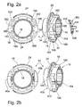
- FIG. 2a, b show those with Fig. 1 shown sliding sleeve 14 with the support member 16 and with two attachments 40a, b before and after their mounting to the radial flange 18.
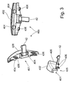
- Such an attachment 40b, the in Fig. 3 is shown enlarged, is designed as a plastic or as a metal-plastic part using a thermoplastic material in the form of a circular disc segment, whose for connection with The rear side 401 provided on the radial flange 18 has two nose-like projections 404 covered by an outer wall section 402, which come from radially outside into two recesses 182 formed on the radial flange 18 (see FIG Fig. 2a, b ) can intervene.
- two rectified spaced apart locking hooks 406 are formed on the underside, which in the assembly of the attachment member 40b in two, formed on the support member 16 of the sliding sleeve 14 latching openings 162 (see Fig. 2a ) and this can engage behind and attach the attachments 40a, b in the cooperation with the projections 404 captive on the sliding sleeve 14.
- the latching openings 162 are in turn formed in a pipe section 164 of the support member 16 radially projecting and over the outer diameter of the pipe section 164 projecting mounting portions 166.
- These attachment portions 166 are mirror-symmetrically provided in pairs on the support member 16, wherein each belonging to a pair of mounting portions 166 form a common contact surface for engagement with the clutch lever 44.
- the axially projecting latching hook 42 for the captive arrangement of the coupling lever 44 can also be seen on the underside 405.
- the latter latching hook 42 can dip on the release device 10 in a space provided between the latching openings 162 of the support member 16 168 space.
- Fig. 2b shows the assembled state of the attachment 40a, wherein the outer wall portion 402 surrounds the radial flange 18 in this peripheral region. It can further be seen that the attachment parts 40a, b in axial, facing away from the release bearing 20 Direction have a convex curved surface 408, so that there reaching the clutch lever 44 can be passed almost smoothly upon actuation of the clutch.
- the attachment element 40 is designed in two parts with the attachment parts 40a, b, which are arranged separately and independently of one another on the carrier element 16. It is alternatively also possible to make this one-piece with two investment areas for an actuator.
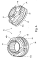
- Fig. 4 shows a perspective view of the mounted release device 10 with the release bearing 20 which is held with the retaining clip 22 on the annular collar 24 of the radial flange 18 and can move laterally on this to enable a self-adjustment.
- Fig. 5 shows a front view of a formed from the release device 10 and the clutch lever 44 preassembled unit.
- the clutch lever 44 is provided in its central region with an approximately slot-shaped recess 442, on the parallel longitudinal sides 444 each have an elongated trough portion 446 is formed for engagement of the latching hooks 42.
- These trough portions 446 are formed in the direction of extension of the recess 442 larger than the latching hooks 42, so that enough freedom of movement for the clutch lever 44 is given when disengaging.
- each of a pair of mounting portions 166 formed contact surface also on the longitudinal sides 444, however in the direction perpendicular to the extension of the recess 442 direction abuts substantially free of play.
- Fig. 6 shows a representation of one opposite Fig. 2 modified locking connection of a support member 160 and an attachment 400, wherein instead of the latching hooks 406 (see Fig. 3 ) on the attachment 400 two axially projecting surface elements 400a, each having a protruding therefrom, in cross-section round Schnappkontur 400b are provided which can be introduced into the attachment areas 160a formed circular openings 160b and snapped or latched there.
- the illustrated elements 160, 400 and their function reference is made to the above description.
Landscapes
- Engineering & Computer Science (AREA)
- General Engineering & Computer Science (AREA)
- Mechanical Engineering (AREA)
- Mechanical Operated Clutches (AREA)
Abstract
Description
- Die vorliegende Erfindung betrifft eine Ausrückvorrichtung für eine Reibungskupplung eines Kraftfahrzeuges gemäß dem Oberbegriff des Patentanspruchs 1. Eine solche Ausrückvorrichtung mit einer mehrteiligen Schiebehülse ist bereits aus der
EP 1 830 094 A1 bekannt. - Wie dieses bereits in dem vorgenannten Stand der Technik erläutert, erfordert eine solche Ausrückvorrichtung zur Betätigung einer Kraftfahrzeugreibungskupplung für jede Fahrzeugplattform eine Einzelfestlegung. Das bedeutet, dass die Ausrückvorrichtung je nach technischer Spezifikation der Kupplung, der zu deren Betätigung erforderlichen Ausrückkräfte und dem in einem Antriebsstrang zur Verfügung stehenden Bauraum speziell ausgelegt und dimensioniert werden muss. Insbesondere variieren dabei das zwischen den Anlagebereichen von Kupplungshebel bzw. Kupplungsgabel und dem Angriffspunkt des Kupplungsbetätigungsorgans, z.B. den Zungenenden einer Membranfeder, vorgegebene Längenmaß, der Innendurchmesser der Schiebehülse sowie die Breite des Anlagebereichs des Kupplungshebels an der Schiebehülse. Beispielsweise sind zur Darstellung von Ausrückvorrichtungen mit verschiedenen Einbaubaulängen selbst bei gleichem Innendurchmesser der Schiebehülse, gleicher Breite des Anlagebereichs für den Kupplungshebel und gleicher Ausrücklagergeometrie eine Mehrzahl unterschiedlicher Schiebehülsen erforderlich, die sich lediglich in dem vorgenannten Längenmaß unterscheiden. Daraus resultiert eine erhebliche und mit hohen Werkzeugkosten verbundene Teilevielfalt.
- Die Erfindung stellt sich von diesem Problem ausgehend die Aufgabe, eine Ausrückvorrichtung bereitzustellen, die die Teilevielfalt und die damit einhergehenden Kosten reduziert.
- Die vorstehend genannte Aufgabe wird gelöst durch eine gattungsgemäße Ausrückvorrichtung mit den kennzeichnenden Merkmalen des Patentanspruchs 1.
- Die Lösung sieht demnach eine Ausrückvorrichtung für eine Reibungskupplung eines Kraftfahrzeuges vor, die zunächst ein Führungsrohr und eine auf diesem axial verlagerbare, mehrteilig ausgeführte Schiebehülse umfasst. Die Schiebehülse weist einen Anlagebereich für ein Betätigungselement zur Aufnahme einer Betätigungskraft und einen Aufnahmebereich für ein koaxial an der Schiebehülse angeordnetes Ausrücklager auf mit einem drehfest zu der Schiebehülse angeordneten ersten Lagerring, Wälzkörpern und einem umlaufenden zweiten Lagerring, der mit einem Betätigungsorgan der Reibungskupplung in Wirkverbindung steht.
- Die erfindungsgemäße Ausrückvorrichtung zeichnet sich dadurch aus, dass die Schiebehülse ein auf dem Führungsrohr angeordnetes Trägerelement und mindestens ein an der Schiebehülse montierbares Anbauelement umfasst, wobei an dem Trägerelement der Aufnahmebereich für das Ausrücklager und an dem Anbauelement der Anlagebereich für das Betätigungselement ausgebildet ist.
- Dadurch wird die Schiebehülse konstruktiv und funktional aufgeteilt in einen ersten Teilbereich, welcher bei mehreren unterschiedlich gestalteten Ausrückvorrichtungen identisch ist und in einen zweiten Teilbereich, welcher bei mehreren unterschiedlich gestalteten Ausrückvorrichtungen verschiedenartig ausgebildet ist. Das heißt, eine erfindungsgemäße Ausrückvorrichtung kann zur Bildung der Schiebehülse in diesem Fall ein, für jeden unterschiedlichen Typ einer Ausrückvorrichtung identisches Trägerelement umfassen, welches mit zumindest einem, je nach spezieller Vorgabe erforderlichen Anbauelement zusammengefügt wird. Auf diese Weise können die erforderlichen Werkzeug- und Herstellungskosten günstiger sein als bei der Fertigung von verschiedenartigen einteiligen Schiebehülsen. Natürlich können umgekehrt auch identische Anbauelemente mit unterschiedlichen Trägerelementen zu einer Schiebehülse kombiniert werden.
- Es ist mit der vorgeschlagenen Lösung nunmehr insbesondere möglich, die bei verschiedenartigen Ausrückvorrichtungen auftretende Varianz im Innendurchmesser der Führungshülse, der Breite und/oder der axialen Erstreckung des Anlagebereichs des Kupplungshebels oder der Einbaulänge nur durch eine der beiden Schiebehülsenteile darzustellen, während das andere Teil, also entweder das Trägerelement oder das Anbauelement unverändert beibehalten werden kann.
- Selbstverständlich ist die erfindungsgemäße mehrteilige Ausführung der Schiebehülse nicht auf eine Zweiteiligkeit beschränkt, vielmehr kann eine Schiebehülse auch aus drei oder noch mehreren Teilen zusammengefügt werden. Auf diese Weise wird ein Teile-Baukasten zur Darstellung von verschiedenen Ausrückvorrichtungen bereitgestellt, wobei eine hohe Anzahl von Gleichteilen verbaut werden kann.
- Die Unteransprüche beschreiben vorteilhafte Ausgestaltungen und Weiterbildungen der Erfindung.
- Gemäß einer ersten vorteilhaften Ausgestaltung der Erfindung wird vorgeschlagen, das Trägerelement mit einem zur Anordnung auf dem Führungsrohr vorgesehenen Kunststoffkörper auszubilden. Zur Erzielung einer hohen Maßhaltigkeit, Temperaturfestigkeit und günstiger Gleiteigenschaften eignet sich als Werkstoff insbesondere ein Duroplast oder aber auch ein wärmebeständiges Thermoplast, wie z.B. Polyamid.
- Es ist weiterhin auch von Vorteil, das Trägerelement als Kunststoff-Metall-Verbundteil auszuführen, um an hochbeanspruchten Bereichen durch implementierte Metalleiemente eine weitere Versteifung der Schiebehülse zu erzielen.
- Von Vorteil umfasst das Trägerelement einen Radialflansch, welcher den Aufnahmebereich für das Ausrücklager bildet. Dieser, unmittelbar im Betätigungskraftfluss liegende Radialflansch wird mit Vorteil anstelle eines für den Führungsbereich vorgesehenen in der Regel spröden Duroplastwerkstoffs aus einem metallischen Werkstoff, beispielsweise einer Stahlscheibe gefertigt, welche mit dem Kunststoff zumindest teilweise umspritzt bzw. umgossen werden kann. Die Werkstoffauswahl kann somit angepasst an die jeweilige Funktion eines Schiebehülsenabschnittes erfolgen. Das Metallteil allgemein oder der metallische Radialflansch kann auch vollständig von einem Kunststoff umschlossen sein, wodurch an der Schiebehülse Korrosionserscheinungen durch in der Getriebeglocke eingeschlossene Feuchtigkeit sicher vermieden werden.
- Günstigerweise wird das zumindest eine Anbauelement mit dem Anlagebereich bzw. -bereichen für das Betätigungselement an dem Radialflansch festgelegt. Das Anbauelement befindet sich damit im an einem Fahrzeug montierten Zustand der Ausrückvorrichtung axial zwischen dem Radialflansch und dem Betätigungselement, so dass das Anbauelement beim Betätigen der Kupplung im Wesentlichen mit einer Axialkraft beaufschlagt wird.
- Zur verliersicheren Anordnung des Anbauelements an der Schiebehülse, genauer an dem Trägerelement, wird vorgeschlagen, dieses dort mittels einer Rastverbindung zu befestigen. Hierfür bieten sich dem Fachmann eine Vielzahl bekannter Lösungen, z.B. verschwenkbare Rasthaken o.ä. an
- Das Anbauelement ist des Weiteren mit Vorteil als Kunststoff- oder als Metall-Kunststoffteil ausgeführt, wobei sich zur Ausbildung von verschwenk- oder verfombaren Rastelementen der Einsatz eines zumindest etwas elastischen Werkstoffs, z.B. eines Thermoplastwerkstoffes, eignet.
- Zur Bildung einer vormontierten Einheit einer Ausrückvorrichtung mit einem Betätigungselement, d.h. einem Ausrückhebel oder einer Ausrückschwinge, umfasst das Anbauelement eine Haltevorrichtung zu dessen verliersicheren Anordnung. Diese Haltevorrichtung kann günstigerweise auch als Schnapp- oder Rastverbindung ausgeführt sein, so dass die Vormontage schnell und werkzeugfrei erfolgen kann.
- Das Anbauelement kann einteilig oder aber auch zweiteilig ausgeführt sein, wobei die beiden Teile zur Anlage den zwei Auflageabschnitten eines Betätigungselementes symmetrisch zur Mittelachse an der Schiebehülse angeordnet sind.
- Der Anlagebereich eines Anbauelements oder die Anlagebereiche der Anbauteile sind mit besonderem Vorteil konvex gewölbt ausgeführt, wodurch eine nahezu reibungsfreie Abwälzbewegung des Betätigungselementes ermöglicht wird.
- Zusätzlich ergeben sich durch die vorgeschlagene Lösung zahlreiche vorteilhafte Montagemöglichkeiten. Die Ausrückvorrichtung kann beispielsweise bereits von einem Zulieferer ggf. in Baueinheit mit einem Kupplungshebel montiert und an einen Fahrzeughersteller als Fertigware geliefert werden. Es besteht jedoch auch die weitere Möglichkeit, die Ausrückvorrichtung mit der erfindungsgemäßen mehrteiligen Schiebehülse als unmontierte Komponenten einem Kunden bereitzustellen, welcher dann in Abhängigkeit von dem jeweils zu bestückenden Fahrzeug die Montage der Schiebehülse und damit der Ausrückvorrichtung vornimmt. Diese Variante ist zum Beispiel sinnvoll, um beim Einbau der Ausrückvorrichtung im Fahrzeug durch Variation eines der Schiebehülsenteile Toleranzen am Einbauort auszugleichen. Des Weiteren kann die Mehrteiligkeit der Schiebehülse vorteilhaft ausgenutzt werden, um der sich bei einem Belagverschleiß der Kupplung einstellenden Verlagerung des Ausrückhubes zu kompensieren. Hierzu kann bei einem Serviceaufenthalt des Fahrzeuges die mehrteilige Schiebehülse der Ausrückvorrichtung demontiert und anschließend wieder zusammengesetzt werden, wobei durch die entsprechende Elementeauswahl nunmehr eine andere Einbaulänge, die sich von der vorherigen unterscheidet, realisiert wird. Gleichfalls bietet sich die Möglichkeit, nur das verschlissene Schiebehülsenteil auszutauschen und das andere, noch funktionsfähige Schiebehülsenteil beizubehalten.
- Im Folgenden wird die Erfindung anhand der beigefügten Figuren beispielhaft erläutert. Es zeigen:
- Fig. 1
- eine Axialschnittdarstellung einer Ausrückvorrichtung mit einer mehrteiligen Schiebehülse;
- Fig. 2a
- eine Darstellung einer Schiebehülse, umfassend ein Trägerelement und ein zweiteiliges Anbauelement vor deren Montage;
- Fig. 2b
- eine perspektivische Darstellung einer Schiebehülse, umfassend ein Trägerelement und ein zweiteiliges Anbauelement nach erfolgter Montage;
- Fig. 3
- ein einzelnes, zur Montage an einem Trägerelement vorgesehenes Anbauelement;
- Fig. 4
- eine perspektivische Darstellung einer montierten Ausrückvorrichtung;
- Fig. 5
- eine Ansicht einer aus der Ausrückvorrichtung und einem Kupplungshebel gebildeten vormontierten Baueinheit;
- Fig. 6
- eine Darstellung einer zu
Fig. 2 alternativen Verbindung von Trägerelement und Anbauelement. -
Fig. 1 zeigt eine Ausrückvorrichtung 10 für eine hier zeichnerisch nicht dargestellte Reibungskupplung eines Kraftfahrzeuges in einem Axialschnitt, die zunächst ein als Strichlinie angedeutetes Führungsrohr 12 und eine auf diesem axial verlagerbare, mehrteilige Schiebehülse 14 umfasst. Die Schiebehülse 14 ist als Metall-Kunststoff-Verbundbauteil ausgeführt und weist ein aus einem Duroplastwerkstoff hergestelltes Trägerelement 16 zu deren Führung auf dem Führungsrohr 12 mit einem an dessen Außenumfang eingefassten metallischen, aus Stahl gefertigten Radialflansch 18 auf, welcher einen Aufnahmebereich 18a zur Aufnahme des Ausrücklagers 20 bereit stellt. - Es ist erkennbar, dass der Radialflansch 18 zumindest in dessen radial inneren Bereich von dem Kunststoff des Trägerelementes 16 eingefasst ist, was durch Anspritzen des Trägerelementes 16 an eine, den Radialflansch 18 bildende Stahlscheibe erfolgen kann. Das Ausrücklager 20 ist mittels einer in
Fig. 1 nur teilweise sichtbaren Halteklammer 22 am Radialflansch 18 angeordnet, die dazu einen dort ausgebildeten unterbrochenen Ringkragen 24 (sieheFig. 4 ) stellenweise umgreifen kann. Das Ausrücklager 20 umfasst im Detail einen drehfest zu der Schiebehülse 14 angeordneten ersten, hierbei äußeren Lagerring 26, Wälzkörper 28 und einem umlaufenden zweiten, hierbei inneren Lagerring 30, der mit einem Betätigungsorgan 32 der Reibungskupplung in Wirkverbindung steht. Der Innenring 30 ist über das axiale Ende des Trägerelementes 16 hinausstehend ausgebildet und bildet einen Radialflansch 34 aus, an den sich über eine Kunststoff-Anlaufscheibe 36 das Betätigungsorgan 32 der Reibungskupplung, z.B. eine Membranfeder, zur Übertragung einer Ausrückkraft anlegen kann. - Auf der dem Ausrücklager 20 am Radialflansch 18 gegenüberliegenden Seite ist ein Anlagebereich 38 für ein Betätigungselement 44 vorgesehen, über welches eine Betätigungskraft zur Betätigung der Reibungskupplung eingeleitet werden kann. Dieser Anlagebereich 38, der auf zwei an der Ausrückachse A gegenüberliegenden Seiten der Ausrückvorrichtung 10 ausgebildet ist, ist an einem an der Schiebehülse 14 montierbaren, hier zweiteilig ausgeführten Anbauelement 40 ausgebildet, welches am Radialflansch 18 befestigt und dort verliersicher durch eine Rastverbindung gehalten wird, wie dieses anhand der weiteren Figuren noch detailliert beschrieben wird. Es sind an dem Anbauelement 40 bzw. an dessen Anbauteilen 40a,b ferner in axialer Richtung abstehende, verschwenkbare Rasthaken 42 erkennbar, die einen Teil einer Haltevorrichtung zur verliersicheren Anordnung des Kupplungshebels 44 (siehe
Fig. 5 ) darstellen und somit zur Bildung einer vormontierten Baueinheit, bestehend aus der Ausrückvorrichtung 10 und dem Kupplungshebel 44, dienen. - Die
Fig. 2a, b zeigen die mitFig. 1 dargestellte Schiebehülse 14 mit dem Trägerelement 16 und mit zwei Anbauteilen 40a,b vor und nach deren Montage an dem Radialflansch 18. Ein solches Anbauteil 40b, das inFig. 3 vergrößert dargestellt ist, ist als Kunststoff- oder als Metall-Kunststoffteil unter Verwendung eines Thermoplastwerkstoffes in Form eines Kreisscheibensegmentes konzipiert, dessen zur Verbindung mit dem Radialflansch 18 vorgesehene Rückseite 401 zwei nasenartige, von einem äußeren Wandungsabschnitt 402 überdeckte Vorsprünge 404 aufweist, welche von radial außen kommend in zwei dazu am Radialflansch 18 ausgebildete Ausnehmungen 182 (sieheFig. 2a, b ) eingreifen können. Zu diesen Vorsprüngen 404 sind an einer Unterseite 405 des Anbauteils 40b zwei gleichgerichtete voneinander beabstandete Rasthaken 406 ausgebildet, die bei der Montage des Anbauelements 40b in zwei, an dem Trägerelement 16 der Schiebehülse 14 ausgebildete Rastöffnungen 162 (sieheFig. 2a ) eintauchen und dieses hintergreifen können und die Anbauteile 40a, b im Zusammenwirken mit den Vorsprüngen 404 verliersicher an der Schiebehülse 14 fixieren. Die Rastöffnungen 162 sind ihrerseits in von einem Rohrabschnitt 164 des Trägerelements 16 radial abstehenden und über dem Außendurchmesser des Rohrabschnittes 164 überstehenden Befestigungsabschnitten 166 ausgebildet. Diese Befestigungsabschnitte 166 sind spiegelsymmetrisch jeweils paarweise am Trägerelement 16 vorgesehen, wobei die jeweils zu einem Paar gehörenden Befestigungsabschnitte 166 eine gemeinsame Anlagefläche zur Anlage an dem Kupplungshebel 44 bilden. - Zwischen den Rasthaken 406 ist ebenfalls an der Unterseite 405 der axial abstehende Rasthaken 42 zur verliersicheren Anordnung des Kupplungshebels 44 erkennbar. Der letztere Rasthaken 42 kann an der Ausrückvorrichtung 10 in eine zwischen den Rastöffnungen 162 des Trägerelements 16 vorgesehenen Freiraum 168 eintauchen.
Fig. 2b zeigt den montierten Zustand des Anbauteils 40a, wobei dessen äußerer Wandungsabschnitt 402 den Radialflansch 18 in diesem Umfangsbereich umgreift. Es ist weiter erkennbar, dass die Anbauteile 40a,b in axialer, von dem Ausrücklager 20 abgewandten Richtung eine konvex gewölbte Oberfläche 408 aufweisen, damit der dort zur Anlage gelangende Kupplungshebel 44 bei einer Betätigung der Kupplung nahezu reibungslos abgewälzt werden kann. - Das Anbauelement 40 ist in dem erläuterten Beispiel zweiteilig mit den Anbauteilen 40a, b ausgeführt, welche getrennt und voneinander unabhängig am Trägerelement 16 angeordnet werden. Es ist alternativ dazu auch möglich, dieses einteilig mit zwei Anlagebereichen für ein Betätigungselement zu gestalten.
-
Fig. 4 zeigt eine perspektivische Darstellung der montierten Ausrückvorrichtung 10 mit dem Ausrücklager 20, welches mit der Halteklammer 22 am Ringkragen 24 des Radialflansches 18 gehalten wird und sich an diesem zur Ermöglichung einer Selbstjustage lateral verlagern kann. -
Fig. 5 zeigt eine Frontansicht einer aus der Ausrückvorrichtung 10 und dem Kupplungshebel 44 gebildeten vormontierten Baueinheit. Der Kupplungshebel 44 ist in dessen Mittenbereich mit einer etwa langlochförmigen Ausnehmung 442 versehen, an deren parallelen Längsseiten 444 jeweils ein länglicher Muldenbereich 446 zum Eingriff der Rasthaken 42 ausgebildet ist. Diese Muldenbereiche 446 sind in der Erstreckungsrichtung der Ausnehmung 442 größer als die Rasthaken 42 ausgebildet, so dass beim Ausrücken genügend Bewegungsspielraum für den Kupplungshebel 44 gegeben ist. Ferner ist inFig. 5 erkennbar, dass die jeweils von einem Paar der Befestigungsabschnitte 166 gebildete Anlagefläche ebenfalls an den Längsseiten 444, jedoch in der zur Erstreckung der Ausnehmung 442 senkrechten Richtung im Wesentlichen spielfrei anliegt. -
Fig. 6 zeigt eine Darstellung einer gegenüberFig. 2 modifizierten Rastverbindung von einem Trägerelement 160 und einem Anbauteil 400, wobei anstelle der Rasthaken 406 (sieheFig. 3 ) an dem Anbauteil 400 zwei axial abstehende Flächenelemente 400a mit jeweils einer davon abstehenden, im Querschnitt runden Schnappkontur 400b vorgesehen sind, welche in an den Befestigungsbereichen 160a ausgebildete kreisförmige Öffnungen 160b eingeführt und dort verschnappt bzw. verrastet werden können. Für weitere Details der dargestellten Elemente 160, 400 und deren Funktion wird auf die vorstehende Beschreibung verwiesen. -
- 10
- Ausrückvorrichtung
- 12
- Führungsrohr
- 14
- Schiebehülse
- 16
- Trägerelement
- 160
- Trägerelement
- 160a
- Befestigungsbereich
- 160b
- Öffnung
- 162
- Rastöffnung
- 164
- Rohrabschnitt
- 166
- Befestigungsabschnitt
- 168
- Freiraum
- 18
- Radialflansch
- 18a
- Aufnahmebereich
- 182
- Ausnehmung
- 20
- Ausrücklager
- 22
- Halteklammer
- 24
- Ringkragen
- 26
- Lageraußenring
- 28
- Wälzkörper
- 30
- Lagerinnenring
- 32
- Betätigungsorgan
- 34
- Radialflansch
- 36
- Anlaufscheibe
- 38
- Anlagebereich
- 40
- Anbauelement
- 400
- Anbauteil
- 400a
- Flächenelement
- 400b
- Schnappkontur
- 40a,b
- Anbauteil
- 401
- Rückseite
- 402
- Wandungsabschnitt
- 404
- Vorsprung
- 405
- Unterseite
- 406
- Rasthaken
- 408
- konvexe Oberfläche
- 42
- Rasthaken
- 44
- Kupplungshebel
- 442
- Ausnehmung
- 444
- Längsseite
- 446
- Muldenbereich
- A
- Ausrückachse
Claims (13)
- Ausrückvorrichtung (10) für eine Reibungskupplung eines Kraftfahrzeuges, umfassend- ein Führungsrohr (12),- eine auf dem Führungsrohr (12) axial verlagerbare, mehrteilig ausgeführte Schiebehülse (14) mit- einem Anlagebereich (38) für ein Betätigungselement zur Aufnahme einer Betätigungskraft und mit- einem Aufnahmebereich (18a) für ein koaxial an der Schiebehülse (14) angeordnetes Ausrücklager (20) mit einem drehfest zu der Schiebehülse (14) angeordneten ersten Lagerring (26), Wälzkörpern (28) und einem umlaufenden zweiten Lagerring (30), der mit einem Betätigungsorgan (32) der Reibungskupplung in Wirkverbindung steht,dadurch gekennzeichnet,
dass die Schiebehülse (14) ein auf dem Führungsrohr (12) angeordnetes Trägerelement (16) und mindestens ein an der Schiebehülse (14) montierbares Anbauelement (40) umfasst, wobei an dem Trägerelement (16) der Aufnahmebereich (18a) für das Ausrücklager (20) und an dem Anbauelement (40) der Anlagebereich (38) für das Betätigungselement ausgebildet ist. - Ausrückvorrichtung nach Anspruch 1,
dadurch gekennzeichnet,
dass das Trägerelement (16) einen zur Anordnung auf dem Führungsrohr (12) vorgesehenen Kunststoffkörper umfasst. - Ausrückvorrichtung nach Anspruch 1 oder 2,
dadurch gekennzeichnet,
dass das Trägerelement (16) als Kunststoff-Metall-Verbundteil ausgeführt ist. - Ausrückvorrichtung nach einem der Ansprüche 1-3,
dadurch gekennzeichnet,
dass das Trägerelement (16) einen Radialflansch (18) umfasst, der den Aufnahmebereich (18a) für das Ausrücklager (20) bildet. - Ausrückvorrichtung nach Anspruch 4,
dadurch gekennzeichnet,
dass der Radialflansch (18) aus einem metallischen Werkstoff gefertigt ist. - Ausrückvorrichtung nach Anspruch 4 oder 5,
dadurch gekennzeichnet,
dass der Radialflansch (18) zumindest teilweise kunststoffumspritzt ist. - Ausrückvorrichtung nach einem der Ansprüche 4-6,
dadurch gekennzeichnet,
dass das Anbauelement (40) an dem Radialflansch (18) festgelegt ist. - Ausrückvorrichtung nach einem der Ansprüche 1-7,
dadurch gekennzeichnet,
dass das Anbauelement (40) mittels einer Rastverbindung an der Schiebehülse (14) verliersicher angeordnet ist. - Ausrückvorrichtung nach einem der Ansprüche 1-8,
dadurch gekennzeichnet,
dass das Anbauelement (40) als Kunststoff- oder als Metall-Kunststoffteil ausgeführt ist. - Ausrückvorrichtung nach einem der Ansprüche 1-9,
dadurch gekennzeichnet,
dass das Anbauelement (40) unter Verwendung eines Thermoplastwerkstoff gefertigt ist. - Ausrückvorrichtung nach einem der Ansprüche 1-10,
dadurch gekennzeichnet,
dass das Anbauelement (40) eine Haltevorrichtung (42) zur verliersicheren Anordnung des Betätigungselementes umfasst. - Ausrückvorrichtung nach einem der Ansprüche 1-11,
dadurch gekennzeichnet,
dass das Anbauelement (40) zweiteilig mit Anbauteilen (40a, b) ausgeführt ist, wobei die Anbauteile (40a, b) symmetrisch zur Mittelachse an der Schiebehülse (14) angeordnet sind. - Ausrückvorrichtung nach einem der Ansprüche 1-12,
dadurch gekennzeichnet,
dass der Anlagebereich (38) des Anbauelements (40) oder der Anbauteile (40a,b) konvex gewölbt ausgeführt ist.
Priority Applications (3)
| Application Number | Priority Date | Filing Date | Title |
|---|---|---|---|
| AT08004832T ATE507406T1 (de) | 2008-03-14 | 2008-03-14 | Ausrückvorrichtung für eine reibungskupplung eines kraftfahrzeuges mit einer mehrteiligen schiebehülse |
| EP08004832A EP2101073B1 (de) | 2008-03-14 | 2008-03-14 | Ausrückvorrichtung für eine Reibungskupplung eines Kraftfahrzeuges mit einer mehrteiligen Schiebehülse |
| DE502008003351T DE502008003351D1 (de) | 2008-03-14 | 2008-03-14 | Ausrückvorrichtung für eine Reibungskupplung eines Kraftfahrzeuges mit einer mehrteiligen Schiebehülse |
Applications Claiming Priority (1)
| Application Number | Priority Date | Filing Date | Title |
|---|---|---|---|
| EP08004832A EP2101073B1 (de) | 2008-03-14 | 2008-03-14 | Ausrückvorrichtung für eine Reibungskupplung eines Kraftfahrzeuges mit einer mehrteiligen Schiebehülse |
Publications (2)
| Publication Number | Publication Date |
|---|---|
| EP2101073A1 true EP2101073A1 (de) | 2009-09-16 |
| EP2101073B1 EP2101073B1 (de) | 2011-04-27 |
Family
ID=39670415
Family Applications (1)
| Application Number | Title | Priority Date | Filing Date |
|---|---|---|---|
| EP08004832A Not-in-force EP2101073B1 (de) | 2008-03-14 | 2008-03-14 | Ausrückvorrichtung für eine Reibungskupplung eines Kraftfahrzeuges mit einer mehrteiligen Schiebehülse |
Country Status (3)
| Country | Link |
|---|---|
| EP (1) | EP2101073B1 (de) |
| AT (1) | ATE507406T1 (de) |
| DE (1) | DE502008003351D1 (de) |
Cited By (1)
| Publication number | Priority date | Publication date | Assignee | Title |
|---|---|---|---|---|
| DE102014224518A1 (de) | 2014-12-01 | 2016-06-02 | Schaeffler Technologies AG & Co. KG | Kupplungsausrücklageranordnung |
Citations (4)
| Publication number | Priority date | Publication date | Assignee | Title |
|---|---|---|---|---|
| JP2001241465A (ja) * | 2000-03-01 | 2001-09-07 | Nachi Fujikoshi Corp | 自動調心型クラッチレリーズ軸受 |
| FR2836969A1 (fr) * | 2002-03-06 | 2003-09-12 | Skf Ab | Systeme de commande d'embrayage pour vehicule automobile et dispositif d'entrainement associe |
| US6702085B1 (en) * | 1999-09-07 | 2004-03-09 | Skf France | Clutch release bearing with self-alignment by means of elastic sleeve |
| EP1830094A1 (de) | 2006-03-03 | 2007-09-05 | Zf Friedrichshafen Ag | Ausrückvorrichtung für eine Reibungskupplung eines Kraftfahrzeuges mit einer mehrteiligen Schiebehülse |
-
2008
- 2008-03-14 AT AT08004832T patent/ATE507406T1/de active
- 2008-03-14 DE DE502008003351T patent/DE502008003351D1/de active Active
- 2008-03-14 EP EP08004832A patent/EP2101073B1/de not_active Not-in-force
Patent Citations (4)
| Publication number | Priority date | Publication date | Assignee | Title |
|---|---|---|---|---|
| US6702085B1 (en) * | 1999-09-07 | 2004-03-09 | Skf France | Clutch release bearing with self-alignment by means of elastic sleeve |
| JP2001241465A (ja) * | 2000-03-01 | 2001-09-07 | Nachi Fujikoshi Corp | 自動調心型クラッチレリーズ軸受 |
| FR2836969A1 (fr) * | 2002-03-06 | 2003-09-12 | Skf Ab | Systeme de commande d'embrayage pour vehicule automobile et dispositif d'entrainement associe |
| EP1830094A1 (de) | 2006-03-03 | 2007-09-05 | Zf Friedrichshafen Ag | Ausrückvorrichtung für eine Reibungskupplung eines Kraftfahrzeuges mit einer mehrteiligen Schiebehülse |
Cited By (3)
| Publication number | Priority date | Publication date | Assignee | Title |
|---|---|---|---|---|
| DE102014224518A1 (de) | 2014-12-01 | 2016-06-02 | Schaeffler Technologies AG & Co. KG | Kupplungsausrücklageranordnung |
| WO2016086925A1 (de) | 2014-12-01 | 2016-06-09 | Schaeffler Technologies AG & Co. KG | Kupplungsausrücklageranordnung |
| DE102014224518B4 (de) * | 2014-12-01 | 2016-11-17 | Schaeffler Technologies AG & Co. KG | Kupplungsausrücklageranordnung |
Also Published As
| Publication number | Publication date |
|---|---|
| EP2101073B1 (de) | 2011-04-27 |
| DE502008003351D1 (de) | 2011-06-09 |
| ATE507406T1 (de) | 2011-05-15 |
Similar Documents
| Publication | Publication Date | Title |
|---|---|---|
| DE2611558C2 (de) | Kupplungsausrücker | |
| DE19752076A1 (de) | Anbindung einer Kolbenstange am Kolben eines Geberzylinders | |
| EP1512882B1 (de) | Hydraulikzylinder | |
| EP1967744B1 (de) | Hydraulikzylinder, insbesondere Geberzylinder für eine hydraulische KFZ-Kupplungs- oder Bremsbetätigung, und Verfahren zur Herstellung eines Kolbens hierfür | |
| DE102015220934B3 (de) | Lenksäule für ein Kraftfahrzeug und Verfahren zur Herstellung einer Lenksäule | |
| DE102010054301A1 (de) | Einrücksystem für eine Kupplung | |
| EP3359833B1 (de) | Reibungskupplung | |
| DE102007051475A1 (de) | Verbindung eines Achsversatzausgleichselements und eines Innenrings eines Wälzlagers | |
| DE19914937B4 (de) | Betätigungsvorrichtung | |
| DE102007008724B4 (de) | Scheibenbremse, insbesondere für ein Nutzfahrzeug | |
| EP2101073B1 (de) | Ausrückvorrichtung für eine Reibungskupplung eines Kraftfahrzeuges mit einer mehrteiligen Schiebehülse | |
| DE102008004324B4 (de) | Scheibenwischeranlage an einem Fahrzeug | |
| DE19846988B4 (de) | Betätigungsvorrichtung für eine Reibungskupplung | |
| EP1891347B1 (de) | Ausrücklager einer schalttrennkupplung | |
| EP2167354B1 (de) | Befestigungsanordnung | |
| DE102007031320A1 (de) | Befestigungs- und Entkoppelungselement zur Montage eines Bauteils bei einem Kraftwagen | |
| DE102012222878A1 (de) | Arbeitszylinder mit Transportsicherung | |
| WO2017137038A1 (de) | Kupplung mit schwimmend gelagerter anlaufscheibe | |
| DE102014215301A1 (de) | Anbindung eines Nehmerzylinders an ein Gehäuse | |
| EP1385076B1 (de) | Drehschaltervorrichtung | |
| DE19709387C2 (de) | Ausrückvorrichtung für eine Reibungskupplung | |
| EP0094001B1 (de) | Reibungskupplung für Kraftfahrzeuge | |
| EP1830094B1 (de) | Ausrückvorrichtung für eine Reibungskupplung eines Kraftfahrzeuges mit einer mehrteiligen Schiebehülse | |
| DE102016202035B3 (de) | Betätigungszylinder mit an ihm befestigten Faltenbalg | |
| DE102014202267A1 (de) | Fußhebelwerk für ein Fahrzeug sowie Lagerachse |
Legal Events
| Date | Code | Title | Description |
|---|---|---|---|
| PUAI | Public reference made under article 153(3) epc to a published international application that has entered the european phase |
Free format text: ORIGINAL CODE: 0009012 |
|
| 17P | Request for examination filed |
Effective date: 20090130 |
|
| AK | Designated contracting states |
Kind code of ref document: A1 Designated state(s): AT BE BG CH CY CZ DE DK EE ES FI FR GB GR HR HU IE IS IT LI LT LU LV MC MT NL NO PL PT RO SE SI SK TR |
|
| AX | Request for extension of the european patent |
Extension state: AL BA MK RS |
|
| AKX | Designation fees paid |
Designated state(s): AT BE BG CH CY CZ DE DK EE ES FI FR GB GR HR HU IE IS IT LI LT LU LV MC MT NL NO PL PT RO SE SI SK TR |
|
| GRAP | Despatch of communication of intention to grant a patent |
Free format text: ORIGINAL CODE: EPIDOSNIGR1 |
|
| GRAS | Grant fee paid |
Free format text: ORIGINAL CODE: EPIDOSNIGR3 |
|
| GRAA | (expected) grant |
Free format text: ORIGINAL CODE: 0009210 |
|
| AK | Designated contracting states |
Kind code of ref document: B1 Designated state(s): AT BE BG CH CY CZ DE DK EE ES FI FR GB GR HR HU IE IS IT LI LT LU LV MC MT NL NO PL PT RO SE SI SK TR |
|
| REG | Reference to a national code |
Ref country code: GB Ref legal event code: FG4D Free format text: NOT ENGLISH |
|
| REG | Reference to a national code |
Ref country code: CH Ref legal event code: EP |
|
| REG | Reference to a national code |
Ref country code: IE Ref legal event code: FG4D Free format text: LANGUAGE OF EP DOCUMENT: GERMAN |
|
| REF | Corresponds to: |
Ref document number: 502008003351 Country of ref document: DE Date of ref document: 20110609 Kind code of ref document: P |
|
| REG | Reference to a national code |
Ref country code: DE Ref legal event code: R096 Ref document number: 502008003351 Country of ref document: DE Effective date: 20110609 |
|
| REG | Reference to a national code |
Ref country code: NL Ref legal event code: VDEP Effective date: 20110427 |
|
| LTIE | Lt: invalidation of european patent or patent extension |
Effective date: 20110427 |
|
| PG25 | Lapsed in a contracting state [announced via postgrant information from national office to epo] |
Ref country code: HR Free format text: LAPSE BECAUSE OF FAILURE TO SUBMIT A TRANSLATION OF THE DESCRIPTION OR TO PAY THE FEE WITHIN THE PRESCRIBED TIME-LIMIT Effective date: 20110427 Ref country code: NO Free format text: LAPSE BECAUSE OF FAILURE TO SUBMIT A TRANSLATION OF THE DESCRIPTION OR TO PAY THE FEE WITHIN THE PRESCRIBED TIME-LIMIT Effective date: 20110727 Ref country code: PT Free format text: LAPSE BECAUSE OF FAILURE TO SUBMIT A TRANSLATION OF THE DESCRIPTION OR TO PAY THE FEE WITHIN THE PRESCRIBED TIME-LIMIT Effective date: 20110829 Ref country code: LT Free format text: LAPSE BECAUSE OF FAILURE TO SUBMIT A TRANSLATION OF THE DESCRIPTION OR TO PAY THE FEE WITHIN THE PRESCRIBED TIME-LIMIT Effective date: 20110427 Ref country code: SE Free format text: LAPSE BECAUSE OF FAILURE TO SUBMIT A TRANSLATION OF THE DESCRIPTION OR TO PAY THE FEE WITHIN THE PRESCRIBED TIME-LIMIT Effective date: 20110427 |
|
| REG | Reference to a national code |
Ref country code: IE Ref legal event code: FD4D |
|
| PG25 | Lapsed in a contracting state [announced via postgrant information from national office to epo] |
Ref country code: LV Free format text: LAPSE BECAUSE OF FAILURE TO SUBMIT A TRANSLATION OF THE DESCRIPTION OR TO PAY THE FEE WITHIN THE PRESCRIBED TIME-LIMIT Effective date: 20110427 Ref country code: SI Free format text: LAPSE BECAUSE OF FAILURE TO SUBMIT A TRANSLATION OF THE DESCRIPTION OR TO PAY THE FEE WITHIN THE PRESCRIBED TIME-LIMIT Effective date: 20110427 Ref country code: GR Free format text: LAPSE BECAUSE OF FAILURE TO SUBMIT A TRANSLATION OF THE DESCRIPTION OR TO PAY THE FEE WITHIN THE PRESCRIBED TIME-LIMIT Effective date: 20110728 Ref country code: ES Free format text: LAPSE BECAUSE OF FAILURE TO SUBMIT A TRANSLATION OF THE DESCRIPTION OR TO PAY THE FEE WITHIN THE PRESCRIBED TIME-LIMIT Effective date: 20110807 Ref country code: IS Free format text: LAPSE BECAUSE OF FAILURE TO SUBMIT A TRANSLATION OF THE DESCRIPTION OR TO PAY THE FEE WITHIN THE PRESCRIBED TIME-LIMIT Effective date: 20110827 Ref country code: CY Free format text: LAPSE BECAUSE OF FAILURE TO SUBMIT A TRANSLATION OF THE DESCRIPTION OR TO PAY THE FEE WITHIN THE PRESCRIBED TIME-LIMIT Effective date: 20110427 Ref country code: FI Free format text: LAPSE BECAUSE OF FAILURE TO SUBMIT A TRANSLATION OF THE DESCRIPTION OR TO PAY THE FEE WITHIN THE PRESCRIBED TIME-LIMIT Effective date: 20110427 |
|
| PG25 | Lapsed in a contracting state [announced via postgrant information from national office to epo] |
Ref country code: NL Free format text: LAPSE BECAUSE OF FAILURE TO SUBMIT A TRANSLATION OF THE DESCRIPTION OR TO PAY THE FEE WITHIN THE PRESCRIBED TIME-LIMIT Effective date: 20110427 |
|
| PG25 | Lapsed in a contracting state [announced via postgrant information from national office to epo] |
Ref country code: CZ Free format text: LAPSE BECAUSE OF FAILURE TO SUBMIT A TRANSLATION OF THE DESCRIPTION OR TO PAY THE FEE WITHIN THE PRESCRIBED TIME-LIMIT Effective date: 20110427 Ref country code: IE Free format text: LAPSE BECAUSE OF FAILURE TO SUBMIT A TRANSLATION OF THE DESCRIPTION OR TO PAY THE FEE WITHIN THE PRESCRIBED TIME-LIMIT Effective date: 20110427 Ref country code: EE Free format text: LAPSE BECAUSE OF FAILURE TO SUBMIT A TRANSLATION OF THE DESCRIPTION OR TO PAY THE FEE WITHIN THE PRESCRIBED TIME-LIMIT Effective date: 20110427 |
|
| PLBI | Opposition filed |
Free format text: ORIGINAL CODE: 0009260 |
|
| PG25 | Lapsed in a contracting state [announced via postgrant information from national office to epo] |
Ref country code: PL Free format text: LAPSE BECAUSE OF FAILURE TO SUBMIT A TRANSLATION OF THE DESCRIPTION OR TO PAY THE FEE WITHIN THE PRESCRIBED TIME-LIMIT Effective date: 20110427 Ref country code: RO Free format text: LAPSE BECAUSE OF FAILURE TO SUBMIT A TRANSLATION OF THE DESCRIPTION OR TO PAY THE FEE WITHIN THE PRESCRIBED TIME-LIMIT Effective date: 20110427 Ref country code: DK Free format text: LAPSE BECAUSE OF FAILURE TO SUBMIT A TRANSLATION OF THE DESCRIPTION OR TO PAY THE FEE WITHIN THE PRESCRIBED TIME-LIMIT Effective date: 20110427 Ref country code: SK Free format text: LAPSE BECAUSE OF FAILURE TO SUBMIT A TRANSLATION OF THE DESCRIPTION OR TO PAY THE FEE WITHIN THE PRESCRIBED TIME-LIMIT Effective date: 20110427 |
|
| PLAX | Notice of opposition and request to file observation + time limit sent |
Free format text: ORIGINAL CODE: EPIDOSNOBS2 |
|
| 26 | Opposition filed |
Opponent name: SCHAEFFLER TECHNOLOGIES AG & CO. KG Effective date: 20120127 |
|
| REG | Reference to a national code |
Ref country code: DE Ref legal event code: R026 Ref document number: 502008003351 Country of ref document: DE Effective date: 20120127 |
|
| PG25 | Lapsed in a contracting state [announced via postgrant information from national office to epo] |
Ref country code: IT Free format text: LAPSE BECAUSE OF FAILURE TO SUBMIT A TRANSLATION OF THE DESCRIPTION OR TO PAY THE FEE WITHIN THE PRESCRIBED TIME-LIMIT Effective date: 20110427 |
|
| PLBB | Reply of patent proprietor to notice(s) of opposition received |
Free format text: ORIGINAL CODE: EPIDOSNOBS3 |
|
| BERE | Be: lapsed |
Owner name: ZF FRIEDRICHSHAFEN A.G. Effective date: 20120331 |
|
| PG25 | Lapsed in a contracting state [announced via postgrant information from national office to epo] |
Ref country code: MC Free format text: LAPSE BECAUSE OF NON-PAYMENT OF DUE FEES Effective date: 20120331 |
|
| REG | Reference to a national code |
Ref country code: CH Ref legal event code: PL |
|
| GBPC | Gb: european patent ceased through non-payment of renewal fee |
Effective date: 20120314 |
|
| REG | Reference to a national code |
Ref country code: FR Ref legal event code: ST Effective date: 20121130 |
|
| PG25 | Lapsed in a contracting state [announced via postgrant information from national office to epo] |
Ref country code: FR Free format text: LAPSE BECAUSE OF NON-PAYMENT OF DUE FEES Effective date: 20120402 Ref country code: GB Free format text: LAPSE BECAUSE OF NON-PAYMENT OF DUE FEES Effective date: 20120314 Ref country code: BE Free format text: LAPSE BECAUSE OF NON-PAYMENT OF DUE FEES Effective date: 20120331 Ref country code: LI Free format text: LAPSE BECAUSE OF NON-PAYMENT OF DUE FEES Effective date: 20120331 Ref country code: CH Free format text: LAPSE BECAUSE OF NON-PAYMENT OF DUE FEES Effective date: 20120331 |
|
| PG25 | Lapsed in a contracting state [announced via postgrant information from national office to epo] |
Ref country code: BG Free format text: LAPSE BECAUSE OF FAILURE TO SUBMIT A TRANSLATION OF THE DESCRIPTION OR TO PAY THE FEE WITHIN THE PRESCRIBED TIME-LIMIT Effective date: 20110727 |
|
| PG25 | Lapsed in a contracting state [announced via postgrant information from national office to epo] |
Ref country code: MT Free format text: LAPSE BECAUSE OF FAILURE TO SUBMIT A TRANSLATION OF THE DESCRIPTION OR TO PAY THE FEE WITHIN THE PRESCRIBED TIME-LIMIT Effective date: 20110427 |
|
| PG25 | Lapsed in a contracting state [announced via postgrant information from national office to epo] |
Ref country code: TR Free format text: LAPSE BECAUSE OF FAILURE TO SUBMIT A TRANSLATION OF THE DESCRIPTION OR TO PAY THE FEE WITHIN THE PRESCRIBED TIME-LIMIT Effective date: 20110427 |
|
| REG | Reference to a national code |
Ref country code: AT Ref legal event code: MM01 Ref document number: 507406 Country of ref document: AT Kind code of ref document: T Effective date: 20130314 |
|
| PG25 | Lapsed in a contracting state [announced via postgrant information from national office to epo] |
Ref country code: LU Free format text: LAPSE BECAUSE OF NON-PAYMENT OF DUE FEES Effective date: 20120314 |
|
| PG25 | Lapsed in a contracting state [announced via postgrant information from national office to epo] |
Ref country code: HU Free format text: LAPSE BECAUSE OF FAILURE TO SUBMIT A TRANSLATION OF THE DESCRIPTION OR TO PAY THE FEE WITHIN THE PRESCRIBED TIME-LIMIT Effective date: 20080314 |
|
| PG25 | Lapsed in a contracting state [announced via postgrant information from national office to epo] |
Ref country code: AT Free format text: LAPSE BECAUSE OF NON-PAYMENT OF DUE FEES Effective date: 20130314 |
|
| PLAB | Opposition data, opponent's data or that of the opponent's representative modified |
Free format text: ORIGINAL CODE: 0009299OPPO |
|
| R26 | Opposition filed (corrected) |
Opponent name: SCHAEFFLER TECHNOLOGIES GMBH & CO. KG Effective date: 20120127 |
|
| PLCK | Communication despatched that opposition was rejected |
Free format text: ORIGINAL CODE: EPIDOSNREJ1 |
|
| APAH | Appeal reference modified |
Free format text: ORIGINAL CODE: EPIDOSCREFNO |
|
| APBM | Appeal reference recorded |
Free format text: ORIGINAL CODE: EPIDOSNREFNO |
|
| APBP | Date of receipt of notice of appeal recorded |
Free format text: ORIGINAL CODE: EPIDOSNNOA2O |
|
| APBQ | Date of receipt of statement of grounds of appeal recorded |
Free format text: ORIGINAL CODE: EPIDOSNNOA3O |
|
| REG | Reference to a national code |
Ref country code: DE Ref legal event code: R100 Ref document number: 502008003351 Country of ref document: DE |
|
| APBU | Appeal procedure closed |
Free format text: ORIGINAL CODE: EPIDOSNNOA9O |
|
| PLBN | Opposition rejected |
Free format text: ORIGINAL CODE: 0009273 |
|
| STAA | Information on the status of an ep patent application or granted ep patent |
Free format text: STATUS: OPPOSITION REJECTED |
|
| 27O | Opposition rejected |
Effective date: 20171208 |
|
| PGFP | Annual fee paid to national office [announced via postgrant information from national office to epo] |
Ref country code: DE Payment date: 20190226 Year of fee payment: 12 |
|
| REG | Reference to a national code |
Ref country code: DE Ref legal event code: R119 Ref document number: 502008003351 Country of ref document: DE |
|
| PG25 | Lapsed in a contracting state [announced via postgrant information from national office to epo] |
Ref country code: DE Free format text: LAPSE BECAUSE OF NON-PAYMENT OF DUE FEES Effective date: 20201001 |