EP2100653A1 - Filter device for aircraft with an element for polarising and inserting the cartridge - Google Patents
Filter device for aircraft with an element for polarising and inserting the cartridge Download PDFInfo
- Publication number
- EP2100653A1 EP2100653A1 EP09290139A EP09290139A EP2100653A1 EP 2100653 A1 EP2100653 A1 EP 2100653A1 EP 09290139 A EP09290139 A EP 09290139A EP 09290139 A EP09290139 A EP 09290139A EP 2100653 A1 EP2100653 A1 EP 2100653A1
- Authority
- EP
- European Patent Office
- Prior art keywords
- tank
- insert
- hydraulic block
- cartridge
- filter
- Prior art date
- Legal status (The legal status is an assumption and is not a legal conclusion. Google has not performed a legal analysis and makes no representation as to the accuracy of the status listed.)
- Granted
Links
- 238000001914 filtration Methods 0.000 claims abstract description 9
- RTAQQCXQSZGOHL-UHFFFAOYSA-N Titanium Chemical compound [Ti] RTAQQCXQSZGOHL-UHFFFAOYSA-N 0.000 claims abstract description 6
- 229910052719 titanium Inorganic materials 0.000 claims abstract description 6
- 239000010936 titanium Substances 0.000 claims abstract description 6
- 229910001220 stainless steel Inorganic materials 0.000 claims abstract description 5
- 239000010935 stainless steel Substances 0.000 claims abstract description 5
- 238000010079 rubber tapping Methods 0.000 claims description 17
- 239000012530 fluid Substances 0.000 description 10
- 230000001351 cycling effect Effects 0.000 description 3
- 239000000463 material Substances 0.000 description 3
- 230000002093 peripheral effect Effects 0.000 description 3
- XAGFODPZIPBFFR-UHFFFAOYSA-N aluminium Chemical compound [Al] XAGFODPZIPBFFR-UHFFFAOYSA-N 0.000 description 2
- 229910052782 aluminium Inorganic materials 0.000 description 2
- 230000000694 effects Effects 0.000 description 2
- 230000000717 retained effect Effects 0.000 description 2
- 241000273930 Brevoortia tyrannus Species 0.000 description 1
- 229910000639 Spring steel Inorganic materials 0.000 description 1
- 238000005452 bending Methods 0.000 description 1
- 230000015556 catabolic process Effects 0.000 description 1
- 238000006731 degradation reaction Methods 0.000 description 1
- 230000006866 deterioration Effects 0.000 description 1
- 230000009977 dual effect Effects 0.000 description 1
- 238000004519 manufacturing process Methods 0.000 description 1
- 230000001681 protective effect Effects 0.000 description 1
- 238000000926 separation method Methods 0.000 description 1
- 230000035939 shock Effects 0.000 description 1
- 238000011282 treatment Methods 0.000 description 1
Images


Classifications
-
- B—PERFORMING OPERATIONS; TRANSPORTING
- B01—PHYSICAL OR CHEMICAL PROCESSES OR APPARATUS IN GENERAL
- B01D—SEPARATION
- B01D29/00—Filters with filtering elements stationary during filtration, e.g. pressure or suction filters, not covered by groups B01D24/00 - B01D27/00; Filtering elements therefor
- B01D29/11—Filters with filtering elements stationary during filtration, e.g. pressure or suction filters, not covered by groups B01D24/00 - B01D27/00; Filtering elements therefor with bag, cage, hose, tube, sleeve or like filtering elements
- B01D29/13—Supported filter elements
- B01D29/15—Supported filter elements arranged for inward flow filtration
-
- B—PERFORMING OPERATIONS; TRANSPORTING
- B01—PHYSICAL OR CHEMICAL PROCESSES OR APPARATUS IN GENERAL
- B01D—SEPARATION
- B01D29/00—Filters with filtering elements stationary during filtration, e.g. pressure or suction filters, not covered by groups B01D24/00 - B01D27/00; Filtering elements therefor
- B01D29/88—Filters with filtering elements stationary during filtration, e.g. pressure or suction filters, not covered by groups B01D24/00 - B01D27/00; Filtering elements therefor having feed or discharge devices
- B01D29/90—Filters with filtering elements stationary during filtration, e.g. pressure or suction filters, not covered by groups B01D24/00 - B01D27/00; Filtering elements therefor having feed or discharge devices for feeding
- B01D29/902—Filters with filtering elements stationary during filtration, e.g. pressure or suction filters, not covered by groups B01D24/00 - B01D27/00; Filtering elements therefor having feed or discharge devices for feeding containing fixed liquid displacement elements or cores
-
- B—PERFORMING OPERATIONS; TRANSPORTING
- B01—PHYSICAL OR CHEMICAL PROCESSES OR APPARATUS IN GENERAL
- B01D—SEPARATION
- B01D35/00—Filtering devices having features not specifically covered by groups B01D24/00 - B01D33/00, or for applications not specifically covered by groups B01D24/00 - B01D33/00; Auxiliary devices for filtration; Filter housing constructions
- B01D35/14—Safety devices specially adapted for filtration; Devices for indicating clogging
- B01D35/153—Anti-leakage or anti-return valves
-
- B—PERFORMING OPERATIONS; TRANSPORTING
- B01—PHYSICAL OR CHEMICAL PROCESSES OR APPARATUS IN GENERAL
- B01D—SEPARATION
- B01D35/00—Filtering devices having features not specifically covered by groups B01D24/00 - B01D33/00, or for applications not specifically covered by groups B01D24/00 - B01D33/00; Auxiliary devices for filtration; Filter housing constructions
- B01D35/30—Filter housing constructions
- B01D35/306—Filter mounting adapter
-
- B—PERFORMING OPERATIONS; TRANSPORTING
- B01—PHYSICAL OR CHEMICAL PROCESSES OR APPARATUS IN GENERAL
- B01D—SEPARATION
- B01D35/00—Filtering devices having features not specifically covered by groups B01D24/00 - B01D33/00, or for applications not specifically covered by groups B01D24/00 - B01D33/00; Auxiliary devices for filtration; Filter housing constructions
- B01D35/30—Filter housing constructions
- B01D35/31—Filter housing constructions including arrangements for environmental protection, e.g. pressure resisting features
-
- B—PERFORMING OPERATIONS; TRANSPORTING
- B01—PHYSICAL OR CHEMICAL PROCESSES OR APPARATUS IN GENERAL
- B01D—SEPARATION
- B01D2201/00—Details relating to filtering apparatus
- B01D2201/40—Special measures for connecting different parts of the filter
- B01D2201/4023—Means for connecting filter housings to supports
-
- B—PERFORMING OPERATIONS; TRANSPORTING
- B01—PHYSICAL OR CHEMICAL PROCESSES OR APPARATUS IN GENERAL
- B01D—SEPARATION
- B01D2201/00—Details relating to filtering apparatus
- B01D2201/40—Special measures for connecting different parts of the filter
- B01D2201/4046—Means for avoiding false mounting of different parts
-
- B—PERFORMING OPERATIONS; TRANSPORTING
- B01—PHYSICAL OR CHEMICAL PROCESSES OR APPARATUS IN GENERAL
- B01D—SEPARATION
- B01D2201/00—Details relating to filtering apparatus
- B01D2201/40—Special measures for connecting different parts of the filter
- B01D2201/4076—Anti-rotational means
Definitions
- the invention relates to a filtering device for an aircraft hydraulic circuit.
- filtering devices for an aircraft hydraulic circuit comprising at least one cartridge filter which is removably attached to a hydraulic block.
- the filter includes a tank that receives a filter cartridge. The tank is screwed on the hydraulic block and is tightened with sufficient torque to ensure mechanical strength in operation of the thread, and in particular to avoid fretting.
- the subject of the invention is a filtering device which does not have the aforementioned drawback.
- a device for aircraft filtering comprising a hydraulic block adapted to receive a removable filter which comprises a tank receiving a cartridge.
- an insert is screwed with tightening into a tapping of the hydraulic block, the insert itself having a tapping in which is engaged a thread of the tank, the hydraulic block further comprising rotational stop means of the tank once it is screwed on the insert.
- the tapping carried out directly in the hydraulic unit and which receives the insert is certainly subjected to a large tightening, but insofar as the insert is not intended to be disassembled in use, the tapping is no longer subject to screwing and frequent unscrewing, which prevents it from suffering a deterioration of fatigue.
- the tapping of the insert which receives the thread of the tank it is not subjected to significant tightening, since the tank is locked in rotation vis-à-vis the insert so that there There is no risk of unscrewing the vessel so that it is unnecessary to clamp the vessel on the insert. Frequent disassembly of the tank therefore does not risk tiring the tapping of the insert.
- an insert makes it possible to avoid that the large tightening torque couples its effects to fatigue cycling caused by the screwing and unscrewing of the filter bowl.
- a material for example stainless steel
- supports much better frequent screwing / unscrewing materials that usually used for the manufacture of hydraulic blocks (aluminum or titanium).
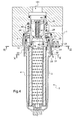
- the filtering device for an aircraft hydraulic circuit comprises a filter 2 comprising a tank 3 which receives a filtering cartridge 4.
- the filter 2 is intended to be attached to a hydraulic block 1 visible to the figures 3 and 4 , and made here in titanium.
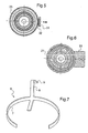
- the tank 3 comprises an internal annular groove 5 in which is inserted a pin 6, more particularly visible at the figure 7 .
- the pin 6 is made here of spring steel, and comprises a belt 7 engaged elastically in the inner annular groove 5 of the vessel 3.
- a polarizer 8 with a curved end 9 extends from the belt 7 upwardly so when the pin 6 is in position on the tank, the bent end 9 passes over the rim of the vessel 3 and protrudes radially from it, as can be seen in FIG. figure 1 .
- a finger 10 extends from the belt towards the bottom of the tank being bent towards the center of the tank 3.
- the cartridge 4 has a foot 11 which centers the cartridge 4 in the tank 3, and a hollow cap 12 having a skirt 13 which cap the outside of the cartridge, and which ends with a redan 14.
- the pin 10 of the pin 6 is pushed towards the wall of the tank 3, which has the effect of locally bending the belt 7, which causes the retraction of the curved end 9 of the polarizer 8 so that the curved end 9 no longer protrudes radially from the rim of the tank 3, as is clearly visible in FIG. figure 2 .
- the hydraulic block 1 comprises a thread 20 in which an insert 21 made of stainless steel here is screwed and tightened with a sufficiently large tightening torque to ensure the mechanical strength in use of the threads.
- the insert 21 is not normally dismounted in service, so that the tapping 20 does not undergo fatigue cycling screwing / unscrewing.
- a tongue 33 is screwed on the hydraulic block 1 facing a peripheral surface of the insert 21 which is notched. As is particularly visible in the figure 6 , the tongue 33 cooperates with the notched peripheral surface of the insert 21 to prevent unscrewing of the latter.
- the tank 3 is screwed not on the hydraulic block 1, but in a tapping 22 of the insert 21. Here, the tank 3 is screwed until a shoulder 23 of the tank 3 comes into contact with the insert 21 .
- a spring blade 30 is screwed on the hydraulic block (here by means of the same screws which hold the tongue 33) to present, on a cantilevered portion 31, a toothed lug 32 which extends towards the shoulder 23 so as to cooperate with peripheral teeth of the latter.
- the interpenetration of the teeth of the shoulder 23 and the teeth of the toothed lug 32 ensures a rotational stop of the vessel 3 vis-à-vis the hydraulic block 1. This interpenetration is illustrated in the figure 5 .
- the leaf spring 30 is rigid enough that in use, the various vibrations and shocks can not cause the separation of the toothed lug 32 and the shoulder 23, so that the tank can not be unscrewed from the insert 21 It will suffice to elastically separate the toothed lug 32 of the shoulder 23, as illustrated by the arrow on the figure 5 to allow screwing or unscrewing of the vessel 3.
- the teeth of the toothed tab 32 may have a shape adapted to allow the spacing of the toothed tab during the rotation of the tank during unscrewing thereof.
- the tapping 20 of the hydraulic block 1, made of titanium is subjected to a major effort, but undergoes no screwing / unscrewing, and therefore does not risk to be damaged if it is properly sized.
- the tapping 22 made in the insert 21 it certainly undergoes screwing / unscrewing, but without significant clamping force, so that it is not likely to deteriorate.
- the embodiment of the insert in stainless steel makes it possible to provide a thread that is not very sensitive to wear due to screwing / unscrewing.
- the insert 21 forms a seat 28 for a valve 24 which is axially movable in the hydraulic block 1.
- the valve 24 cooperates with the seat 28 to close a communication between a first port 100 of the hydraulic block 1 and the inside of the insert 21.
- the lower end of the valve 24 comes to cap a stick 18 of the cap 12 of the cartridge 4 and is pushed against a spring 25 by the cap 12 to open a passage between the port 100 and the outside of the cartridge 4.
- a seal 19 extends between the stick 18 and the valve 24, which tends, during removal of the filter, to retain the cartridge on the valve 24.
- the finger 10 of the pin 6 has precisely the function of fighting against this restraint and force the cartridge to come with the tank during unscrewing of it.
- valve 24 is hollow and forms a channel to a second port 101 of the hydraulic block 1 communicating the interior of the cartridge 4 and the second port 101.
- the hydraulic fluid flows from the first port 100 to the second port 101 having passed through the cartridge 4.
- the valve 24 is internally equipped with a non-return member 40 having a non-return valve 41 pushed by a spring 43 to a seat 42 made in the hollow of the valve 24.
- the non-return valve 41 is pushed back by the fluid coming from the inside of the cartridge against the spring 43.
- a dead volume V of fluid (marked by dots on the figure 4 ) extends between the upper end of the tank 3 and the seat 28 of the insert 21.
- the volume occupied by the valve 24 in the tank 3 when the filter 2 is in place on the hydraulic block 1 is intended to be more important than the dead volume V.
- the fluid contained in the dead volume V gradually takes place in the tank 3 as the valve 24 out of the tank 3 and thus releases in the tank 3 of the volume available to receive this fluid.
- the rotating immobilization member of the vessel as comprising a toothed lug which cooperates with a toothed shoulder of the vessel, it may provide any other equivalent member, such as for example a retractable finger entering a hollow made in the wall of the tank.
Abstract
Description
L'invention concerne un dispositif de filtrage pour circuit hydraulique d'aéronef.The invention relates to a filtering device for an aircraft hydraulic circuit.
On connaît des dispositifs de filtrage pour circuit hydraulique d'aéronef comportant au moins un filtre à cartouche qui est rapporté de façon démontable sur un bloc hydraulique. Le filtre comporte une cuve qui reçoit une cartouche de filtrage. La cuve est vissée sur le bloc hydraulique et est serrée avec un couple suffisant pour assurer une tenue mécanique en service du filetage, et notamment éviter tout fretting.There are known filtering devices for an aircraft hydraulic circuit comprising at least one cartridge filter which is removably attached to a hydraulic block. The filter includes a tank that receives a filter cartridge. The tank is screwed on the hydraulic block and is tightened with sufficient torque to ensure mechanical strength in operation of the thread, and in particular to avoid fretting.
Compte tenu des dimensions des aéronefs envisagés, les cuves atteignent des dimensions appréciables, de sorte que le couple de serrage augmente en proportion, ce qui pose divers problèmes. D'une part, la mise en place d'un tel couple entraîne l'usage de clés dynamométriques de taille et de poids importants, difficiles à manipuler, surtout dans des endroits peu accessibles des soutes de l'aéronef. Ces clés obligent en outre l'opérateur à développer des efforts importants. D'autre part, un tel couple de serrage conduit à des contraintes importantes sur le taraudage du bloc hydraulique. Compte tenu du cyclage en fatigue provoqué par les divers vissages et revissages de la cuve, ces contraintes importantes constituent un risque de dégradation du taraudage du bloc hydraulique 1. Ces risques sont aggravés par le fait que le bloc hydraulique est généralement réalisé dans des matériaux comme l'aluminium ou le titane dans lesquels les taraudages sont connus pour s'user rapidement, même en prévoyant des traitements de protection.Given the dimensions of the aircraft envisaged, the tanks reach appreciable dimensions, so that the tightening torque proportionally increases, which poses various problems. On the one hand, the introduction of such a torque leads to the use of torque wrenches of size and weight, difficult to handle, especially in inaccessible places bunkers of the aircraft. These keys also require the operator to develop significant efforts. On the other hand, such a tightening torque leads to significant constraints on the tapping of the hydraulic block. Given the fatigue cycling caused by the various screwings and screwings of the tank, these important constraints constitute a risk of degradation of the tapping of the
L'invention a pour objet un dispositif de filtrage ne présentant pas l'inconvénient précité.The subject of the invention is a filtering device which does not have the aforementioned drawback.
Selon l'invention, on propose un dispositif de filtrage pour aéronef comprenant un bloc hydraulique adapté à recevoir un filtre amovible qui comporte une cuve recevant une cartouche. Selon l'invention, un insert est vissé avec serrage dans un taraudage du bloc hydraulique, l'insert comportant lui-même un taraudage dans lequel est engagé un filetage de la cuve, le bloc hydraulique comportant en outre des moyens d'arrêt en rotation de la cuve une fois celle-ci vissée sur l'insert.According to the invention, a device for aircraft filtering comprising a hydraulic block adapted to receive a removable filter which comprises a tank receiving a cartridge. According to the invention, an insert is screwed with tightening into a tapping of the hydraulic block, the insert itself having a tapping in which is engaged a thread of the tank, the hydraulic block further comprising rotational stop means of the tank once it is screwed on the insert.
Le taraudage réalisé directement dans le bloc hydraulique et qui reçoit l'insert est certes soumis à un serrage important, mais dans la mesure où l'insert n'est pas destiné à être démonté en service, le taraudage n'est plus soumis à des vissages et des dévissages fréquents, ce qui lui évite de subir une détérioration de fatigue. Quant au taraudage de l'insert qui reçoit le filetage de la cuve, il n'est pas soumis à des serrages importants, puisque la cuve est bloquée en rotation vis-à-vis de l'insert de sorte qu'il n'y a aucun risque de dévissage de la cuve de sorte qu'il est inutile de serrer la cuve sur l'insert. Les démontages fréquents de la cuve ne risquent donc pas de fatiguer le taraudage de l'insert.The tapping carried out directly in the hydraulic unit and which receives the insert is certainly subjected to a large tightening, but insofar as the insert is not intended to be disassembled in use, the tapping is no longer subject to screwing and frequent unscrewing, which prevents it from suffering a deterioration of fatigue. As for the tapping of the insert which receives the thread of the tank, it is not subjected to significant tightening, since the tank is locked in rotation vis-à-vis the insert so that there There is no risk of unscrewing the vessel so that it is unnecessary to clamp the vessel on the insert. Frequent disassembly of the tank therefore does not risk tiring the tapping of the insert.
Ainsi, l'utilisation d'un insert permet d'éviter que le couple de serrage important ne couple ses effets aux cyclages en fatigue provoqué par les vissages et dévissages de la cuve du filtre. De plus, on peut choisir l'insert dans un matériau (par exemple de l'acier inoxydable) qui supporte beaucoup mieux les fréquents vissages/dévissages que les matériaux habituellement utilisés pour la fabrication des blocs hydrauliques (aluminium ou titane).Thus, the use of an insert makes it possible to avoid that the large tightening torque couples its effects to fatigue cycling caused by the screwing and unscrewing of the filter bowl. In addition, one can choose the insert in a material (for example stainless steel) that supports much better frequent screwing / unscrewing materials that usually used for the manufacture of hydraulic blocks (aluminum or titanium).
L'invention sera mieux comprise à la lumière de la description qui suit en référence aux figures des dessins annexés parmi lesquelles :
- la
figure 1 est une vue en coupe longitudinale d'une cuve de filtre d'un dispositif de filtrage selon un mode particulier de réalisation de l'invention ; - la
figure 2 est une vue analogue à celle de lafigure 1 , montrant la cuve de lafigure 1 dans laquelle une cartouche a été introduite ; - la
figure 3 est une vue en coupe longitudinale du dispositif de filtrage dans lequel la cuve du filtre est présentée en regard du bloc hydraulique alors que la cuve ne contient aucune cartouche ; - la
figure 4 est une vue en coupe du dispositif de filtrage selon l'invention avec le filtre de lafigure 3 en place sur le bloc hydraulique ; - la
figure 5 est une vue en coupe selon la ligne V-V de lafigure 4 ; - la
figure 6 est une vue en coupe selon la ligne VI-VI de lafigure 4 ; - la
figure 7 est une vue en perspective d'une épingle équipant la cuve de lafigure 1 .
- the
figure 1 is a longitudinal sectional view of a filter tank of a filter device according to a particular embodiment of the invention; - the
figure 2 is a view similar to that of thefigure 1 , showing the tank of thefigure 1 in which a cartridge has been introduced; - the
figure 3 is a longitudinal sectional view of the filter device in which the filter tank is presented facing the hydraulic block while the tank contains no cartridge; - the
figure 4 is a sectional view of the filter device according to the invention with the filter of thefigure 3 in place on the hydraulic block; - the
figure 5 is a sectional view along line VV of thefigure 4 ; - the
figure 6 is a sectional view along the line VI-VI of thefigure 4 ; - the
figure 7 is a perspective view of a pin equipping the tank of thefigure 1 .
Selon l'invention, et en référence aux
La cuve 3 comporte une gorge annulaire interne 5 dans laquelle est insérée une épingle 6, plus particulièrement visible à la
Revenant aux
L'épingle 6 joue donc un double rôle :
- elle empêche le montage du filtre 2 sur le
bloc hydraulique 1 si une cartouche n'a pas préalablement été mise en place dansla cuve 3. Dans cette situation illustrée à lafigure 3 ,l'extrémité recourbée 9 empêche tout vissage de la cuve 3 sur lebloc hydraulique 1 ; - elle retient la cartouche 4 dans la cuve 3 lors du démontage de celle-ci, par coopération de l'extrémité du doigt 10 avec le redan 14 du
chapeau 12 qui forme un obstacle venant buter contre l'extrémité du doigt 10, ce qui lors du démontage du filtre, obligela cartouche 4 à venir avec la cuve 3. Pour retirer la cartouche 4 de la cuve 3 lorsque le filtre 2 est démonté dubloc hydraulique 1, il convient de retirer l'épingle 6, ou à tout le moins d'écarter le doigt 10 duredan 14.
- it prevents the mounting of the
filter 2 on thehydraulic block 1 if a cartridge has not previously been placed in thetank 3. In this situation illustrated in FIG.figure 3 , thebent end 9 prevents any screwing of thetank 3 on thehydraulic block 1; - it holds the
cartridge 4 in thetank 3 during disassembly thereof, by cooperation of the end of thefinger 10 with thestep 14 of thecap 12 which forms an obstacle abutting against the end of thefinger 10, which then the removal of the filter, forces thecartridge 4 to come with thetank 3. To remove thecartridge 4 from thetank 3 when thefilter 2 is removed from thehydraulic block 1, it is necessary to remove thepin 6, or at the very least to remove thefinger 10 from theredan 14.
Selon l'invention, et en référence aux
Pour assurer ce vissage, une languette 33 est vissée sur le bloc hydraulique 1 en regard d'une surface périphérique de l'insert 21 qui est crantée. Comme cela est particulièrement visible à la
La cuve 3 est elle vissée non pas sur le bloc hydraulique 1, mais dans un taraudage 22 de l'insert 21. Ici, la cuve 3 est vissée jusqu'à contact d'un épaulement 23 de la cuve 3 contre l'insert 21.The
Revenant à la
En variante, les dents de la patte dentée 32 pourront présenter une forme propre à permettre l'écartement de la patte dentée lors de la rotation de la cuve au cours d'un dévissage de celle-ci.Alternatively, the teeth of the
Ainsi, il est inutile de serrer fortement la cuve 3 dans le taraudage de l'insert 21, puisque la cuve ne peut se dévisser en service. Le taraudage 22 qui reçoit la cuve 3 est donc certes soumis à des vissages et dévissages fréquents, mais sans serrage, de sorte que ces vissages/dévissages ne risquent pas de dégrader le taraudage 22 en fatigue.Thus, it is unnecessary to strongly tighten the
Ainsi, le taraudage 20 du bloc hydraulique 1, réalisé dans du titane, est soumis à un effort important, mais ne subit aucun vissage/dévissage, et ne risque donc pas de s'abîmer s'il est bien dimensionné. Quant au taraudage 22 réalisé dans l'insert 21, il subit certes des vissages/dévissages, mais sans effort de serrage significatif, de sorte qu'il ne risque pas non plus de se détériorer. La réalisation de l'insert dans de l'acier inoxydable permet de proposer un taraudage peu sensible à l'usure due aux vissages/dévissages.Thus, the tapping 20 of the
Selon une disposition particulière, l'insert 21 forme un siège 28 pour un clapet 24 qui est mobile axialement dans le bloc hydraulique 1. Comme cela est visible à la
Sur cette même figure, on constate que le clapet 24 est creux et forme un canal vers un deuxième port 101 du bloc hydraulique 1 mettant en communication l'intérieur de la cartouche 4 et le deuxième port 101. Le fluide hydraulique circule ainsi du premier port 100 vers le second port 101 en ayant passé au travers de la cartouche 4. Pour éviter tout retour de fluide vers le premier port 100, le clapet 24 est équipé intérieurement d'un organe anti-retour 40 comportant un clapet anti-retour 41 poussé par un ressort 43 vers un siège 42 réalisé dans le creux du clapet 24. Le clapet anti-retour 41 est repoussé par le fluide provenant de l'intérieur de la cartouche à l'encontre du ressort 43.In this same figure, it is found that the
On remarquera que lorsque le filtre 2 est en place sur le bloc hydraulique 1, un volume mort V de fluide (repéré par des points sur la
Lorsque l'on retire le filtre 2 du bloc hydraulique 1, tout le fluide hydraulique contenu dans la cuve vient avec le filtre 2, tandis que tout le fluide contenu dans le bloc hydraulique 1 au dessus du siège 28 reste dans le bloc hydraulique en étant retenu par le clapet 24 qui se ferme. Cependant, le fluide contenu dans le volume mort V, s'étendant entre le siège 28 et l'extrémité haute de la cuve 3 n'est ni contenu dans la cuve 3 ni retenu par le clapet 24.When removing the
Pour éviter que le volume mort V ne se déverse vers l'extérieur lors du démontage du filtre, et selon l'invention, le volume occupé par le clapet 24 dans la cuve 3 lorsque le filtre 2 est en place sur le bloc hydraulique 1 est prévu pour être plus important que le volume mort V. De cette façon, lors du dévissage de la cuve 3, le fluide contenu dans le volume mort V prend progressivement place dans la cuve 3 au fur et à mesure que le clapet 24 sort de la cuve 3 et libère ainsi dans la cuve 3 du volume disponible pour recevoir ce fluide. En s'assurant que le volume libéré est plus grand que le volume mort V, on évite tout déversement de fluide vers l'extérieur lors du démontage du filtre 2, mis à part quelques gouttes.To prevent the dead volume V from flowing outwards during the dismantling of the filter, and according to the invention, the volume occupied by the
L'invention n'est pas limitée à ce qui vient d'être décrit, mais bien au contraire englobe toute variante entrant dans le cadre défini par les revendications.The invention is not limited to what has just been described, but on the contrary encompasses any variant within the scope defined by the claims.
En particulier, bien que l'on ait décrit l'organe d'immobilisation en rotation de la cuve comme comprenant une patte dentée qui coopérait avec un épaulement denté de la cuve, on pourra prévoir tout autre organe équivalent, comme par exemple un doigt escamotable rentrant dans un creux réalisé dans la paroi de la cuve.In particular, although it has been described the rotating immobilization member of the vessel as comprising a toothed lug which cooperates with a toothed shoulder of the vessel, it may provide any other equivalent member, such as for example a retractable finger entering a hollow made in the wall of the tank.
Claims (3)
Applications Claiming Priority (1)
| Application Number | Priority Date | Filing Date | Title |
|---|---|---|---|
| FR0801411A FR2928558B1 (en) | 2008-03-14 | 2008-03-14 | AIRCRAFT FILTERING DEVICE WITH STOP ROTATING THE FILTER |
Publications (2)
| Publication Number | Publication Date |
|---|---|
| EP2100653A1 true EP2100653A1 (en) | 2009-09-16 |
| EP2100653B1 EP2100653B1 (en) | 2011-08-31 |
Family
ID=39884457
Family Applications (1)
| Application Number | Title | Priority Date | Filing Date |
|---|---|---|---|
| EP09290139A Active EP2100653B1 (en) | 2008-03-14 | 2009-02-27 | Filter device for aircraft with an element for polarising and inserting the cartridge |
Country Status (9)
| Country | Link |
|---|---|
| US (1) | US20090229231A1 (en) |
| EP (1) | EP2100653B1 (en) |
| JP (1) | JP2009222230A (en) |
| CN (1) | CN101530687A (en) |
| AT (1) | ATE522266T1 (en) |
| AU (1) | AU2009201003A1 (en) |
| BR (1) | BRPI0900404A2 (en) |
| CA (1) | CA2658066C (en) |
| FR (1) | FR2928558B1 (en) |
Families Citing this family (9)
| Publication number | Priority date | Publication date | Assignee | Title |
|---|---|---|---|---|
| US20120181362A1 (en) | 2009-09-28 | 2012-07-19 | Panasonic Corporation | Rotary cooking device |
| JP5663394B2 (en) * | 2011-05-06 | 2015-02-04 | 株式会社コガネイ | Container detachment device for tempering equipment |
| JP5765560B2 (en) * | 2011-05-09 | 2015-08-19 | Smc株式会社 | Filter device |
| JP5713289B2 (en) | 2011-05-09 | 2015-05-07 | Smc株式会社 | Case structure of fluid pressure equipment |
| CN102997027A (en) * | 2012-12-05 | 2013-03-27 | 江苏科雷斯普能源科技有限公司 | Novel precise filter |
| DE102014212923A1 (en) * | 2014-07-03 | 2016-01-07 | Mahle International Gmbh | filtering device |
| EP3669087B1 (en) | 2017-08-14 | 2023-02-15 | Asco, L.P. | A grounded filter regulator lubricator |
| DE102020000738A1 (en) * | 2020-02-03 | 2021-08-05 | H Y D A C Filtertechnik GmbH | Filter device and filter element |
| CN113719687B (en) * | 2021-08-30 | 2022-11-08 | 中国航发贵阳发动机设计研究所 | Large-flow fuel filtering and sealing structure |
Citations (4)
| Publication number | Priority date | Publication date | Assignee | Title |
|---|---|---|---|---|
| US3023906A (en) * | 1958-11-21 | 1962-03-06 | Winslow Engineering And Mfg Co | Filter |
| DE19703648A1 (en) * | 1996-01-31 | 1997-08-07 | Caterpillar Inc | Filter unit with stainless steel casing preventing pollution, waste of materials and loss of time |
| US5711872A (en) * | 1994-06-15 | 1998-01-27 | Jones; John A. | Reusable oil filter assembly |
| US20070045171A1 (en) * | 2005-08-23 | 2007-03-01 | Toyota Boshoku Kabushiki Kaisha | Element replacement type filter |
Family Cites Families (2)
| Publication number | Priority date | Publication date | Assignee | Title |
|---|---|---|---|---|
| US1744837A (en) * | 1926-01-23 | 1930-01-28 | Pelco Auto Products Inc | Liquid-fuel purifier |
| US2932400A (en) * | 1957-04-01 | 1960-04-12 | Purolator Products Inc | Filter unit |
-
2008
- 2008-03-14 FR FR0801411A patent/FR2928558B1/en active Active
-
2009
- 2009-02-27 AT AT09290139T patent/ATE522266T1/en not_active IP Right Cessation
- 2009-02-27 EP EP09290139A patent/EP2100653B1/en active Active
- 2009-03-10 US US12/401,177 patent/US20090229231A1/en not_active Abandoned
- 2009-03-12 BR BRPI0900404-1A patent/BRPI0900404A2/en not_active IP Right Cessation
- 2009-03-12 CA CA2658066A patent/CA2658066C/en not_active Expired - Fee Related
- 2009-03-12 AU AU2009201003A patent/AU2009201003A1/en not_active Abandoned
- 2009-03-13 JP JP2009061939A patent/JP2009222230A/en active Pending
- 2009-03-13 CN CN200910128741A patent/CN101530687A/en active Pending
Patent Citations (4)
| Publication number | Priority date | Publication date | Assignee | Title |
|---|---|---|---|---|
| US3023906A (en) * | 1958-11-21 | 1962-03-06 | Winslow Engineering And Mfg Co | Filter |
| US5711872A (en) * | 1994-06-15 | 1998-01-27 | Jones; John A. | Reusable oil filter assembly |
| DE19703648A1 (en) * | 1996-01-31 | 1997-08-07 | Caterpillar Inc | Filter unit with stainless steel casing preventing pollution, waste of materials and loss of time |
| US20070045171A1 (en) * | 2005-08-23 | 2007-03-01 | Toyota Boshoku Kabushiki Kaisha | Element replacement type filter |
Also Published As
| Publication number | Publication date |
|---|---|
| CA2658066C (en) | 2011-03-29 |
| FR2928558A1 (en) | 2009-09-18 |
| JP2009222230A (en) | 2009-10-01 |
| FR2928558B1 (en) | 2014-04-11 |
| US20090229231A1 (en) | 2009-09-17 |
| ATE522266T1 (en) | 2011-09-15 |
| BRPI0900404A2 (en) | 2009-11-03 |
| AU2009201003A1 (en) | 2009-10-01 |
| CA2658066A1 (en) | 2009-09-14 |
| EP2100653B1 (en) | 2011-08-31 |
| CN101530687A (en) | 2009-09-16 |
Similar Documents
| Publication | Publication Date | Title |
|---|---|---|
| EP2100653B1 (en) | Filter device for aircraft with an element for polarising and inserting the cartridge | |
| EP2100655B1 (en) | Cartridge filter for aircraft | |
| CH702865A2 (en) | mobile watch. | |
| FR2927143A1 (en) | FEMALE CONNECTING ELEMENT AND RAPID CONNECTING INCORPORATING SUCH A MEMBER | |
| EP2100654B1 (en) | Filter device for aircraft with an element for polarising and inserting the cartridge | |
| EP2354002B1 (en) | Method and device for emptying a tank, tank and aircraft provided with such a device | |
| CH700722B1 (en) | The portable schedule. | |
| EP1423285B1 (en) | Device for mounting a sensor on a motor vehicle wheel rim and related mounting method | |
| FR2973094A3 (en) | CONNECTING DEVICE FOR RIGID OR FLEXIBLE CONDUITS WITH MOUNTING STATUS INDICATOR | |
| CA3135534C (en) | Connecting device with an intermediate unlocking position | |
| FR2554543A1 (en) | Connection for rapidly fitting a pipework pipe into a tapped hole. | |
| FR2579288A1 (en) | CLOSURE AND DEVICE FOR CLOSING A MANUALLY RELEASABLE DRAIN PORT | |
| FR2885819A1 (en) | Oil filter for internal combustion engine, has emptying piston mounted sliding in cover by spring which contacts with bypass derivation valve assembly so that detent of spring slides with respect to assembly, and flexile finger | |
| CA2630931C (en) | Device and method for drilling a pipeline provided with a derivation plate | |
| EP2090818B1 (en) | Plug for the filling valve body of an automobile air-conditioning circuit | |
| FR2880295A1 (en) | Inflatable tire`s valve core dismounting tool, has dismounting unit comprising rod with pin that is supported against extension of plug when core is released, where extension extends within body comprising filtering unit and perforations | |
| FR3092881A1 (en) | Discharge equipment for hydraulic circuit | |
| FR2859248A1 (en) | Dual direction pump for inflating vehicle tyres or balls, has backflow preventing valves at inlet and outlet in head section of pump | |
| EP2907622A1 (en) | Screwing device and screwing tool including such a device | |
| FR3095489A1 (en) | Inflation and deflation valve for inflatable product | |
| EP2335879A1 (en) | Pliers for disassembing a windscreen wiper arm and associated disassembling method | |
| WO2018115020A1 (en) | Purging system with rotating connector | |
| FR3070136A1 (en) | TOOLING ASSEMBLY OF TWO CONDUITS | |
| FR2513727A1 (en) | Adaptor for liquefied gas cylinder - has interior push valve operating cylinder flap valve only after sealed fitting | |
| FR2975085A1 (en) | Housing for water circulating pump in swimming pool, has cam connected to screw, where end of cam is connected to receptacle such that nut is moved between locking position and unlocking position |
Legal Events
| Date | Code | Title | Description |
|---|---|---|---|
| PUAI | Public reference made under article 153(3) epc to a published international application that has entered the european phase |
Free format text: ORIGINAL CODE: 0009012 |
|
| AK | Designated contracting states |
Kind code of ref document: A1 Designated state(s): AT BE BG CH CY CZ DE DK EE ES FI FR GB GR HR HU IE IS IT LI LT LU LV MC MK MT NL NO PL PT RO SE SI SK TR |
|
| AX | Request for extension of the european patent |
Extension state: AL BA RS |
|
| 17P | Request for examination filed |
Effective date: 20100216 |
|
| 17Q | First examination report despatched |
Effective date: 20100316 |
|
| AKX | Designation fees paid |
Designated state(s): AT BE BG CH CY CZ DE DK EE ES FI FR GB GR HR HU IE IS IT LI LT LU LV MC MK MT NL NO PL PT RO SE SI SK TR |
|
| GRAP | Despatch of communication of intention to grant a patent |
Free format text: ORIGINAL CODE: EPIDOSNIGR1 |
|
| GRAS | Grant fee paid |
Free format text: ORIGINAL CODE: EPIDOSNIGR3 |
|
| GRAA | (expected) grant |
Free format text: ORIGINAL CODE: 0009210 |
|
| RAP1 | Party data changed (applicant data changed or rights of an application transferred) |
Owner name: MESSIER-BUGATTI-DOWTY |
|
| AK | Designated contracting states |
Kind code of ref document: B1 Designated state(s): AT BE BG CH CY CZ DE DK EE ES FI FR GB GR HR HU IE IS IT LI LT LU LV MC MK MT NL NO PL PT RO SE SI SK TR |
|
| REG | Reference to a national code |
Ref country code: GB Ref legal event code: FG4D Free format text: NOT ENGLISH Ref country code: CH Ref legal event code: EP |
|
| REG | Reference to a national code |
Ref country code: IE Ref legal event code: FG4D Free format text: LANGUAGE OF EP DOCUMENT: FRENCH |
|
| REG | Reference to a national code |
Ref country code: DE Ref legal event code: R096 Ref document number: 602009002393 Country of ref document: DE Effective date: 20111110 |
|
| REG | Reference to a national code |
Ref country code: NL Ref legal event code: VDEP Effective date: 20110831 |
|
| LTIE | Lt: invalidation of european patent or patent extension |
Effective date: 20110831 |
|
| PG25 | Lapsed in a contracting state [announced via postgrant information from national office to epo] |
Ref country code: IS Free format text: LAPSE BECAUSE OF FAILURE TO SUBMIT A TRANSLATION OF THE DESCRIPTION OR TO PAY THE FEE WITHIN THE PRESCRIBED TIME-LIMIT Effective date: 20111231 Ref country code: NL Free format text: LAPSE BECAUSE OF FAILURE TO SUBMIT A TRANSLATION OF THE DESCRIPTION OR TO PAY THE FEE WITHIN THE PRESCRIBED TIME-LIMIT Effective date: 20110831 Ref country code: NO Free format text: LAPSE BECAUSE OF FAILURE TO SUBMIT A TRANSLATION OF THE DESCRIPTION OR TO PAY THE FEE WITHIN THE PRESCRIBED TIME-LIMIT Effective date: 20111130 Ref country code: SE Free format text: LAPSE BECAUSE OF FAILURE TO SUBMIT A TRANSLATION OF THE DESCRIPTION OR TO PAY THE FEE WITHIN THE PRESCRIBED TIME-LIMIT Effective date: 20110831 Ref country code: LT Free format text: LAPSE BECAUSE OF FAILURE TO SUBMIT A TRANSLATION OF THE DESCRIPTION OR TO PAY THE FEE WITHIN THE PRESCRIBED TIME-LIMIT Effective date: 20110831 Ref country code: HR Free format text: LAPSE BECAUSE OF FAILURE TO SUBMIT A TRANSLATION OF THE DESCRIPTION OR TO PAY THE FEE WITHIN THE PRESCRIBED TIME-LIMIT Effective date: 20110831 Ref country code: FI Free format text: LAPSE BECAUSE OF FAILURE TO SUBMIT A TRANSLATION OF THE DESCRIPTION OR TO PAY THE FEE WITHIN THE PRESCRIBED TIME-LIMIT Effective date: 20110831 |
|
| REG | Reference to a national code |
Ref country code: AT Ref legal event code: MK05 Ref document number: 522266 Country of ref document: AT Kind code of ref document: T Effective date: 20110831 |
|
| PG25 | Lapsed in a contracting state [announced via postgrant information from national office to epo] |
Ref country code: GR Free format text: LAPSE BECAUSE OF FAILURE TO SUBMIT A TRANSLATION OF THE DESCRIPTION OR TO PAY THE FEE WITHIN THE PRESCRIBED TIME-LIMIT Effective date: 20111201 Ref country code: LV Free format text: LAPSE BECAUSE OF FAILURE TO SUBMIT A TRANSLATION OF THE DESCRIPTION OR TO PAY THE FEE WITHIN THE PRESCRIBED TIME-LIMIT Effective date: 20110831 Ref country code: SI Free format text: LAPSE BECAUSE OF FAILURE TO SUBMIT A TRANSLATION OF THE DESCRIPTION OR TO PAY THE FEE WITHIN THE PRESCRIBED TIME-LIMIT Effective date: 20110831 Ref country code: CY Free format text: LAPSE BECAUSE OF FAILURE TO SUBMIT A TRANSLATION OF THE DESCRIPTION OR TO PAY THE FEE WITHIN THE PRESCRIBED TIME-LIMIT Effective date: 20110831 Ref country code: AT Free format text: LAPSE BECAUSE OF FAILURE TO SUBMIT A TRANSLATION OF THE DESCRIPTION OR TO PAY THE FEE WITHIN THE PRESCRIBED TIME-LIMIT Effective date: 20110831 |
|
| REG | Reference to a national code |
Ref country code: IE Ref legal event code: FD4D |
|
| PG25 | Lapsed in a contracting state [announced via postgrant information from national office to epo] |
Ref country code: IE Free format text: LAPSE BECAUSE OF FAILURE TO SUBMIT A TRANSLATION OF THE DESCRIPTION OR TO PAY THE FEE WITHIN THE PRESCRIBED TIME-LIMIT Effective date: 20110831 Ref country code: SK Free format text: LAPSE BECAUSE OF FAILURE TO SUBMIT A TRANSLATION OF THE DESCRIPTION OR TO PAY THE FEE WITHIN THE PRESCRIBED TIME-LIMIT Effective date: 20110831 Ref country code: CZ Free format text: LAPSE BECAUSE OF FAILURE TO SUBMIT A TRANSLATION OF THE DESCRIPTION OR TO PAY THE FEE WITHIN THE PRESCRIBED TIME-LIMIT Effective date: 20110831 |
|
| PG25 | Lapsed in a contracting state [announced via postgrant information from national office to epo] |
Ref country code: EE Free format text: LAPSE BECAUSE OF FAILURE TO SUBMIT A TRANSLATION OF THE DESCRIPTION OR TO PAY THE FEE WITHIN THE PRESCRIBED TIME-LIMIT Effective date: 20110831 Ref country code: IT Free format text: LAPSE BECAUSE OF FAILURE TO SUBMIT A TRANSLATION OF THE DESCRIPTION OR TO PAY THE FEE WITHIN THE PRESCRIBED TIME-LIMIT Effective date: 20110831 Ref country code: RO Free format text: LAPSE BECAUSE OF FAILURE TO SUBMIT A TRANSLATION OF THE DESCRIPTION OR TO PAY THE FEE WITHIN THE PRESCRIBED TIME-LIMIT Effective date: 20110831 Ref country code: PL Free format text: LAPSE BECAUSE OF FAILURE TO SUBMIT A TRANSLATION OF THE DESCRIPTION OR TO PAY THE FEE WITHIN THE PRESCRIBED TIME-LIMIT Effective date: 20110831 Ref country code: PT Free format text: LAPSE BECAUSE OF FAILURE TO SUBMIT A TRANSLATION OF THE DESCRIPTION OR TO PAY THE FEE WITHIN THE PRESCRIBED TIME-LIMIT Effective date: 20120102 |
|
| PG25 | Lapsed in a contracting state [announced via postgrant information from national office to epo] |
Ref country code: DK Free format text: LAPSE BECAUSE OF FAILURE TO SUBMIT A TRANSLATION OF THE DESCRIPTION OR TO PAY THE FEE WITHIN THE PRESCRIBED TIME-LIMIT Effective date: 20110831 |
|
| PLBE | No opposition filed within time limit |
Free format text: ORIGINAL CODE: 0009261 |
|
| STAA | Information on the status of an ep patent application or granted ep patent |
Free format text: STATUS: NO OPPOSITION FILED WITHIN TIME LIMIT |
|
| 26N | No opposition filed |
Effective date: 20120601 |
|
| BERE | Be: lapsed |
Owner name: MESSIER-BUGATTI-DOWTY Effective date: 20120228 |
|
| REG | Reference to a national code |
Ref country code: DE Ref legal event code: R097 Ref document number: 602009002393 Country of ref document: DE Effective date: 20120601 |
|
| PG25 | Lapsed in a contracting state [announced via postgrant information from national office to epo] |
Ref country code: MC Free format text: LAPSE BECAUSE OF NON-PAYMENT OF DUE FEES Effective date: 20120229 |
|
| PG25 | Lapsed in a contracting state [announced via postgrant information from national office to epo] |
Ref country code: BE Free format text: LAPSE BECAUSE OF NON-PAYMENT OF DUE FEES Effective date: 20120228 |
|
| PG25 | Lapsed in a contracting state [announced via postgrant information from national office to epo] |
Ref country code: MK Free format text: LAPSE BECAUSE OF FAILURE TO SUBMIT A TRANSLATION OF THE DESCRIPTION OR TO PAY THE FEE WITHIN THE PRESCRIBED TIME-LIMIT Effective date: 20110831 |
|
| PG25 | Lapsed in a contracting state [announced via postgrant information from national office to epo] |
Ref country code: ES Free format text: LAPSE BECAUSE OF FAILURE TO SUBMIT A TRANSLATION OF THE DESCRIPTION OR TO PAY THE FEE WITHIN THE PRESCRIBED TIME-LIMIT Effective date: 20111211 |
|
| PG25 | Lapsed in a contracting state [announced via postgrant information from national office to epo] |
Ref country code: BG Free format text: LAPSE BECAUSE OF FAILURE TO SUBMIT A TRANSLATION OF THE DESCRIPTION OR TO PAY THE FEE WITHIN THE PRESCRIBED TIME-LIMIT Effective date: 20111130 |
|
| PG25 | Lapsed in a contracting state [announced via postgrant information from national office to epo] |
Ref country code: MT Free format text: LAPSE BECAUSE OF FAILURE TO SUBMIT A TRANSLATION OF THE DESCRIPTION OR TO PAY THE FEE WITHIN THE PRESCRIBED TIME-LIMIT Effective date: 20110831 |
|
| REG | Reference to a national code |
Ref country code: CH Ref legal event code: PL |
|
| PG25 | Lapsed in a contracting state [announced via postgrant information from national office to epo] |
Ref country code: LI Free format text: LAPSE BECAUSE OF NON-PAYMENT OF DUE FEES Effective date: 20130228 Ref country code: CH Free format text: LAPSE BECAUSE OF NON-PAYMENT OF DUE FEES Effective date: 20130228 |
|
| PG25 | Lapsed in a contracting state [announced via postgrant information from national office to epo] |
Ref country code: TR Free format text: LAPSE BECAUSE OF FAILURE TO SUBMIT A TRANSLATION OF THE DESCRIPTION OR TO PAY THE FEE WITHIN THE PRESCRIBED TIME-LIMIT Effective date: 20110831 |
|
| PG25 | Lapsed in a contracting state [announced via postgrant information from national office to epo] |
Ref country code: LU Free format text: LAPSE BECAUSE OF NON-PAYMENT OF DUE FEES Effective date: 20120227 |
|
| PG25 | Lapsed in a contracting state [announced via postgrant information from national office to epo] |
Ref country code: HU Free format text: LAPSE BECAUSE OF FAILURE TO SUBMIT A TRANSLATION OF THE DESCRIPTION OR TO PAY THE FEE WITHIN THE PRESCRIBED TIME-LIMIT Effective date: 20090227 |
|
| REG | Reference to a national code |
Ref country code: DE Ref legal event code: R082 Ref document number: 602009002393 Country of ref document: DE Representative=s name: SCHAUMBURG & PARTNER PATENTANWAELTE GBR, DE Ref country code: DE Ref legal event code: R082 Ref document number: 602009002393 Country of ref document: DE Representative=s name: SCHAUMBURG & PARTNER PATENTANWAELTE MBB, DE Ref country code: DE Ref legal event code: R082 Ref document number: 602009002393 Country of ref document: DE Representative=s name: SCHAUMBURG UND PARTNER PATENTANWAELTE MBB, DE |
|
| REG | Reference to a national code |
Ref country code: FR Ref legal event code: PLFP Year of fee payment: 8 |
|
| REG | Reference to a national code |
Ref country code: FR Ref legal event code: PLFP Year of fee payment: 9 |
|
| REG | Reference to a national code |
Ref country code: FR Ref legal event code: CD Owner name: MESSIER-BUGATTI-DOWTY, FR Effective date: 20170518 |
|
| REG | Reference to a national code |
Ref country code: FR Ref legal event code: PLFP Year of fee payment: 10 |
|
| PGFP | Annual fee paid to national office [announced via postgrant information from national office to epo] |
Ref country code: DE Payment date: 20220119 Year of fee payment: 14 |
|
| PGFP | Annual fee paid to national office [announced via postgrant information from national office to epo] |
Ref country code: FR Payment date: 20230119 Year of fee payment: 15 |
|
| REG | Reference to a national code |
Ref country code: DE Ref legal event code: R119 Ref document number: 602009002393 Country of ref document: DE |
|
| PG25 | Lapsed in a contracting state [announced via postgrant information from national office to epo] |
Ref country code: DE Free format text: LAPSE BECAUSE OF NON-PAYMENT OF DUE FEES Effective date: 20230901 |
|
| PGFP | Annual fee paid to national office [announced via postgrant information from national office to epo] |
Ref country code: GB Payment date: 20240123 Year of fee payment: 16 |