EP2100633A1 - Medizinische Vorrichtung und Ladestation dafür - Google Patents
Medizinische Vorrichtung und Ladestation dafür Download PDFInfo
- Publication number
- EP2100633A1 EP2100633A1 EP08004343A EP08004343A EP2100633A1 EP 2100633 A1 EP2100633 A1 EP 2100633A1 EP 08004343 A EP08004343 A EP 08004343A EP 08004343 A EP08004343 A EP 08004343A EP 2100633 A1 EP2100633 A1 EP 2100633A1
- Authority
- EP
- European Patent Office
- Prior art keywords
- medical device
- energy
- energy supply
- battery
- reservoir
- Prior art date
- Legal status (The legal status is an assumption and is not a legal conclusion. Google has not performed a legal analysis and makes no representation as to the accuracy of the status listed.)
- Granted
Links
- 238000012544 monitoring process Methods 0.000 claims abstract description 4
- WHXSMMKQMYFTQS-UHFFFAOYSA-N Lithium Chemical compound [Li] WHXSMMKQMYFTQS-UHFFFAOYSA-N 0.000 claims description 17
- 229910052744 lithium Inorganic materials 0.000 claims description 17
- 229920000642 polymer Polymers 0.000 claims description 16
- 239000000446 fuel Substances 0.000 claims description 14
- 238000007789 sealing Methods 0.000 claims description 13
- 239000012530 fluid Substances 0.000 claims description 5
- 235000019504 cigarettes Nutrition 0.000 claims description 4
- 230000001360 synchronised effect Effects 0.000 claims 1
- NOESYZHRGYRDHS-UHFFFAOYSA-N insulin Chemical compound N1C(=O)C(NC(=O)C(CCC(N)=O)NC(=O)C(CCC(O)=O)NC(=O)C(C(C)C)NC(=O)C(NC(=O)CN)C(C)CC)CSSCC(C(NC(CO)C(=O)NC(CC(C)C)C(=O)NC(CC=2C=CC(O)=CC=2)C(=O)NC(CCC(N)=O)C(=O)NC(CC(C)C)C(=O)NC(CCC(O)=O)C(=O)NC(CC(N)=O)C(=O)NC(CC=2C=CC(O)=CC=2)C(=O)NC(CSSCC(NC(=O)C(C(C)C)NC(=O)C(CC(C)C)NC(=O)C(CC=2C=CC(O)=CC=2)NC(=O)C(CC(C)C)NC(=O)C(C)NC(=O)C(CCC(O)=O)NC(=O)C(C(C)C)NC(=O)C(CC(C)C)NC(=O)C(CC=2NC=NC=2)NC(=O)C(CO)NC(=O)CNC2=O)C(=O)NCC(=O)NC(CCC(O)=O)C(=O)NC(CCCNC(N)=N)C(=O)NCC(=O)NC(CC=3C=CC=CC=3)C(=O)NC(CC=3C=CC=CC=3)C(=O)NC(CC=3C=CC(O)=CC=3)C(=O)NC(C(C)O)C(=O)N3C(CCC3)C(=O)NC(CCCCN)C(=O)NC(C)C(O)=O)C(=O)NC(CC(N)=O)C(O)=O)=O)NC(=O)C(C(C)CC)NC(=O)C(CO)NC(=O)C(C(C)O)NC(=O)C1CSSCC2NC(=O)C(CC(C)C)NC(=O)C(NC(=O)C(CCC(N)=O)NC(=O)C(CC(N)=O)NC(=O)C(NC(=O)C(N)CC=1C=CC=CC=1)C(C)C)CC1=CN=CN1 NOESYZHRGYRDHS-UHFFFAOYSA-N 0.000 description 16
- 102000004877 Insulin Human genes 0.000 description 8
- 108090001061 Insulin Proteins 0.000 description 8
- 229940125396 insulin Drugs 0.000 description 8
- AZDRQVAHHNSJOQ-UHFFFAOYSA-N alumane Chemical class [AlH3] AZDRQVAHHNSJOQ-UHFFFAOYSA-N 0.000 description 3
- 239000003708 ampul Substances 0.000 description 3
- 238000001514 detection method Methods 0.000 description 3
- 239000011888 foil Substances 0.000 description 3
- WQZGKKKJIJFFOK-GASJEMHNSA-N Glucose Natural products OC[C@H]1OC(O)[C@H](O)[C@@H](O)[C@@H]1O WQZGKKKJIJFFOK-GASJEMHNSA-N 0.000 description 2
- 238000010586 diagram Methods 0.000 description 2
- 230000003203 everyday effect Effects 0.000 description 2
- 239000008103 glucose Substances 0.000 description 2
- 238000012360 testing method Methods 0.000 description 2
- XLYOFNOQVPJJNP-UHFFFAOYSA-N water Substances O XLYOFNOQVPJJNP-UHFFFAOYSA-N 0.000 description 2
- 239000008280 blood Substances 0.000 description 1
- 210000004369 blood Anatomy 0.000 description 1
- 238000011109 contamination Methods 0.000 description 1
- 230000001419 dependent effect Effects 0.000 description 1
- 238000013461 design Methods 0.000 description 1
- 206010012601 diabetes mellitus Diseases 0.000 description 1
- 238000011156 evaluation Methods 0.000 description 1
- 238000007654 immersion Methods 0.000 description 1
- 238000003780 insertion Methods 0.000 description 1
- 230000037431 insertion Effects 0.000 description 1
- 230000010354 integration Effects 0.000 description 1
- 238000005259 measurement Methods 0.000 description 1
- 239000004033 plastic Substances 0.000 description 1
- 229920003023 plastic Polymers 0.000 description 1
- 238000004321 preservation Methods 0.000 description 1
Images


Classifications
-
- A—HUMAN NECESSITIES
- A61—MEDICAL OR VETERINARY SCIENCE; HYGIENE
- A61M—DEVICES FOR INTRODUCING MEDIA INTO, OR ONTO, THE BODY; DEVICES FOR TRANSDUCING BODY MEDIA OR FOR TAKING MEDIA FROM THE BODY; DEVICES FOR PRODUCING OR ENDING SLEEP OR STUPOR
- A61M5/00—Devices for bringing media into the body in a subcutaneous, intra-vascular or intramuscular way; Accessories therefor, e.g. filling or cleaning devices, arm-rests
- A61M5/14—Infusion devices, e.g. infusing by gravity; Blood infusion; Accessories therefor
- A61M5/1413—Modular systems comprising interconnecting elements
-
- A—HUMAN NECESSITIES
- A61—MEDICAL OR VETERINARY SCIENCE; HYGIENE
- A61M—DEVICES FOR INTRODUCING MEDIA INTO, OR ONTO, THE BODY; DEVICES FOR TRANSDUCING BODY MEDIA OR FOR TAKING MEDIA FROM THE BODY; DEVICES FOR PRODUCING OR ENDING SLEEP OR STUPOR
- A61M5/00—Devices for bringing media into the body in a subcutaneous, intra-vascular or intramuscular way; Accessories therefor, e.g. filling or cleaning devices, arm-rests
- A61M5/14—Infusion devices, e.g. infusing by gravity; Blood infusion; Accessories therefor
- A61M5/142—Pressure infusion, e.g. using pumps
- A61M5/14244—Pressure infusion, e.g. using pumps adapted to be carried by the patient, e.g. portable on the body
-
- A—HUMAN NECESSITIES
- A61—MEDICAL OR VETERINARY SCIENCE; HYGIENE
- A61N—ELECTROTHERAPY; MAGNETOTHERAPY; RADIATION THERAPY; ULTRASOUND THERAPY
- A61N1/00—Electrotherapy; Circuits therefor
- A61N1/18—Applying electric currents by contact electrodes
- A61N1/32—Applying electric currents by contact electrodes alternating or intermittent currents
- A61N1/36—Applying electric currents by contact electrodes alternating or intermittent currents for stimulation
- A61N1/372—Arrangements in connection with the implantation of stimulators
- A61N1/378—Electrical supply
-
- A—HUMAN NECESSITIES
- A61—MEDICAL OR VETERINARY SCIENCE; HYGIENE
- A61M—DEVICES FOR INTRODUCING MEDIA INTO, OR ONTO, THE BODY; DEVICES FOR TRANSDUCING BODY MEDIA OR FOR TAKING MEDIA FROM THE BODY; DEVICES FOR PRODUCING OR ENDING SLEEP OR STUPOR
- A61M2205/00—General characteristics of the apparatus
- A61M2205/16—General characteristics of the apparatus with back-up system in case of failure
-
- A—HUMAN NECESSITIES
- A61—MEDICAL OR VETERINARY SCIENCE; HYGIENE
- A61M—DEVICES FOR INTRODUCING MEDIA INTO, OR ONTO, THE BODY; DEVICES FOR TRANSDUCING BODY MEDIA OR FOR TAKING MEDIA FROM THE BODY; DEVICES FOR PRODUCING OR ENDING SLEEP OR STUPOR
- A61M2205/00—General characteristics of the apparatus
- A61M2205/17—General characteristics of the apparatus with redundant control systems
-
- A—HUMAN NECESSITIES
- A61—MEDICAL OR VETERINARY SCIENCE; HYGIENE
- A61M—DEVICES FOR INTRODUCING MEDIA INTO, OR ONTO, THE BODY; DEVICES FOR TRANSDUCING BODY MEDIA OR FOR TAKING MEDIA FROM THE BODY; DEVICES FOR PRODUCING OR ENDING SLEEP OR STUPOR
- A61M2205/00—General characteristics of the apparatus
- A61M2205/82—Internal energy supply devices
- A61M2205/8206—Internal energy supply devices battery-operated
-
- H—ELECTRICITY
- H02—GENERATION; CONVERSION OR DISTRIBUTION OF ELECTRIC POWER
- H02J—CIRCUIT ARRANGEMENTS OR SYSTEMS FOR SUPPLYING OR DISTRIBUTING ELECTRIC POWER; SYSTEMS FOR STORING ELECTRIC ENERGY
- H02J2310/00—The network for supplying or distributing electric power characterised by its spatial reach or by the load
- H02J2310/10—The network having a local or delimited stationary reach
- H02J2310/20—The network being internal to a load
- H02J2310/23—The load being a medical device, a medical implant, or a life supporting device
-
- H—ELECTRICITY
- H02—GENERATION; CONVERSION OR DISTRIBUTION OF ELECTRIC POWER
- H02J—CIRCUIT ARRANGEMENTS OR SYSTEMS FOR SUPPLYING OR DISTRIBUTING ELECTRIC POWER; SYSTEMS FOR STORING ELECTRIC ENERGY
- H02J7/00—Circuit arrangements for charging or depolarising batteries or for supplying loads from batteries
- H02J7/0042—Circuit arrangements for charging or depolarising batteries or for supplying loads from batteries characterised by the mechanical construction
- H02J7/0044—Circuit arrangements for charging or depolarising batteries or for supplying loads from batteries characterised by the mechanical construction specially adapted for holding portable devices containing batteries
-
- H—ELECTRICITY
- H02—GENERATION; CONVERSION OR DISTRIBUTION OF ELECTRIC POWER
- H02J—CIRCUIT ARRANGEMENTS OR SYSTEMS FOR SUPPLYING OR DISTRIBUTING ELECTRIC POWER; SYSTEMS FOR STORING ELECTRIC ENERGY
- H02J7/00—Circuit arrangements for charging or depolarising batteries or for supplying loads from batteries
- H02J7/34—Parallel operation in networks using both storage and other dc sources, e.g. providing buffering
- H02J7/342—The other DC source being a battery actively interacting with the first one, i.e. battery to battery charging
Definitions
- the invention relates to a medical device according to the preamble of claim 1 and a charging station according to the preamble of claim 21.
- the invention relates to a medical device for diabetes treatment.
- the medical device may, for example, be a medical dosing device, such as an insulin pump, or a blood glucose meter.
- portable medical devices are powered by non-rechargeable batteries.
- a medical device that has an energy supply and a control unit for monitoring and controlling the energy supply.
- the energy supply comprises at least two energy sources, of which at least one energy source constitutes a backup energy source.
- the at least one energy source that constitutes the backup energy source may also be used for supplying energy in cases where no backup is needed for the one or more other energy sources.
- the control unit is designed such that it can detect a fault in the energy sources and can disconnect the faulty energy source upon fault detection.
- the medical device according to the invention constitutes a redundant system that is fail-safe or single fault safe. If one of the energy sources fails then the other or one of the other energy sources will function as backup energy source and either take over the function of the faulty energy source or provide enough energy to serve as emergency energy supply for triggering an alarm. Thus fail-safe operation of the medical device is ensured even if a fault occurs in one of the energy sources of the energy supply.
- the control unit preferably comprises means for measuring and evaluating the output voltage and/or current of each energy source and means for disconnecting each energy source from the rest of the medical device, i.e. the load of the energy supply.
- the control unit comprises a control subunit for each energy source, wherein each control subunit has means for measuring and evaluating the output voltage and/or current of its associated energy source and means for disconnecting the associated energy source from the load.
- the load is basically the actual pump.
- the energy supply is rechargeable, wherein the energy supply preferentially comprises a lithium(-ion) polymer battery with at least two battery stacks.
- Each battery stack constitutes one energy source and has a terminal or contact on positive potential and a terminal or contact on negative potential.
- Each battery stack may furthermore comprise one or more battery cells, in particular one or more battery bi-cells.
- a bi-cell is defined as a cell with one anode and two cathodes, the cathodes being positioned on either sides of the anode. The height of a bi-cell lies, for example, in the range of 600 to 800 micrometers.
- Lithium(-ion) polymer batteries are robust to physical damage and can be cost-efficiently manufactured. Furthermore, as lithium(-ion) polymer batteries are rechargeable the user does not have to purchase a new energy supply once the original one has been discharged.
- the energy provided by a lithium(-ion) polymer battery per volume is basically optimal, which broadens application/device integration possibilities and possibly prolongs the running time. Due to the polymeric nature no rigid casing is required, so that lithium(-ion) polymer batteries can be specifically shaped to fit the medical device they shall supply with energy. This has the advantage that the space that is provided by a medical device for an energy supply can be optimally utilized. For a given shape optimal capacity of the energy source can be provided.
- lithium(-ion) polymer batteries can be manufactured to be very thin, also the medical devices they power such as insulin pumps can be made very thin, so that they can be more discreetly employed/used by a user.
- the medical devices they power such as insulin pumps can be made very thin, so that they can be more discreetly employed/used by a user.
- the weight of the medical device can be optimized, i.e. reduced, leading to an easier-to-carry medical device.
- basically optimal volumetric density of the lithium(-ion) polymer batteries longest possible running time of the energy supply of the medical device can be ensured.
- the energy supply with lithium(-ion) polymer batteries is generally robust, i.e. tolerant, with respect to temperature and power variations in particular due to small internal resistance.
- the charging station comprises as energy supplying means an USB-plug, a line connector (also called network connector), a solar cell panel, a primary battery, a plug for a car cigarette lighter outlet, a connector for a mobile phone accumulator and/or a dynamo with a crank handle.
- energy supplying means an USB-plug, a line connector (also called network connector), a solar cell panel, a primary battery, a plug for a car cigarette lighter outlet, a connector for a mobile phone accumulator and/or a dynamo with a crank handle.
- Preferably at least two different energy supplying means are provided.
- the user is not restricted to one type of energy (e.g. a primary battery) but can switch to a different kind of energy, in particular to a different kind of primary energy, (e.g. solar energy or the energy provided by a car battery via a cigarette lighter outlet) which is available at that moment.
- the charging station gives the user more individuality and flexibility.
- the user can charge the energy supply of his medical device according to his needs, which makes the charging individual, and according to the energy resources at hand (i.e. according to availability).
- the user can quickly adapt to outer circumstances, e.g. if he is in the office he may e.g. use the line connector or the USB-plug, on vacation he may e.g. use solar energy or the dynamo by rotating the crank handle etc.
- the depicted medical devices may for example be medical dosing devices such as insulin pumps.
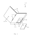
- FIG 1 schematically shows a first embodiment of medical device 1.1 with a top cover 2.
- the top cover 2 forms part of the housing 3.1 of the medical device 1.1.
- the top cover 2 is preferably mounted pivotally on hinges 6.
- the medical device 1.1 has a compartment 4 for a replaceable energy supply 5.1.
- the replaceability of the energy supply 5.1 is indicated in Figure 1 by the bent arrow.
- the energy supply 5.1 is placed in the compartment 4 and, hence, into the housing 3.1 of the medical device 1.1. Therefore, no specific sealing functions have to be performed by the outer surfaces of the energy supply 5.1/compartment 4 and no specific sealing or gaskets have to be provided at the contact surfaces of the energy supply 5.1/compartment 4.
- the sealing function is performed by the top cover 2 or housing 3.1, see exemplarily the sealing or gaskets 39 depicted in Figure 1 .
- FIG. 2 shows another embodiment of a medical device 1.2 with a replaceable energy supply 5.2.
- the dashed arrow indicates how the energy supply 5.2 can be exchanged.
- part of the housing 3.2 of the medical device 1.2 is formed by a housing 7 of the energy supply 5.2.
- the contact surface 8, which is the outer surface with the terminals 9 (also called contacts 9) of the energy supply 5.2 is preferably provided with a sealing/one or more gasket, in particular to protect the medical device 1.2 against humidity. That is, the terminals 9 are sealed. For simplicity, only two terminals 9 are shown. Due to the sealing/gasket it is ensured that the medical device 1.2 conforms to IPX8 (international protection rating X8), i.e. the medical device 1.2 is protected against harmful ingress of water up to and beyond 1 meter.
- IPX8 international protection rating X8
- FIG 3 depicts an energy supply 5.3 (corresponding to the energy supplies 5.1 and 5.2 of Figures 1 and 2 , respectively) of a medical device according to the invention.
- the energy supply 5.3 comprises a rechargeable lithium(-ion) polymer battery with e.g. a nominal cell voltage of 3.7 Volt.
- the energy supply 5.3 furthermore preferably comprises a fuel gauge unit 10 for estimating and monitoring its remaining running time or life time, respectively.
- fuel gauge unit 10 determines the remaining running time via energy or impedance measuring.
- the fuel gauge unit 10 constitutes so-called “smart" electronics.
- the lithium(-ion) polymer battery which may consist of several battery cells, in particular bi-cells, it is possible to integrate two or more battery stacks, each consisting of battery cells, as independent energy sources in one replaceable unit (namely the energy supply).
- the lithium(-ion) polymer battery exemplarily comprises two battery stacks 11 with each battery stack 11 representing one energy source (confer Figures 5 to 8 ).
- Each energy source/battery stack 11 has a terminal 9 on a positive potential and a terminal 9 on negative potential. With two battery stacks 11 there are therefore four terminals 9.
- each energy source/battery stack 11 is provided with a protection circuit 12 for protection against overcharge and/or overvoltage and/or undervoltage.
- each energy source/battery stack 11 can have its own fuel gauge unit 10 allotted to it.
- the fuel gauge unit 10 and the protection circuit 12 are preferably enclosed by the housing 7 of the energy supply (confer Figures 5 to 8 ) and are thus integrated in the energy supply 5.3.
- the medical device may comprise a reservoir for a fluid. If the medical device is, for example, an insulin pump, it typically comprises as reservoir an ampoule for insulin.
- the medical device is constructed such that the reservoir is supported and carried by the energy supply.
- Fig. 4 depicts an energy supply 5.4, which corresponds to the energy supplies 5.1, 5.2 and 5.3 of Figures 1 to 3 , that has a cavity 13 for accommodating such a reservoir 14.
- the cavity 13 is exemplarily formed such that it can accommodate a cylindrically shaped reservoir 14 such as an ampoule of an insulin pump.
- the reservoir 14 can either be enclosed by the housing of the energy supply 5.4 or it can be held and supported by the housing of the energy supply 5.4, the housing forming the cavity 13.
- the energy supply can carry other or further components of the medical device e.g. one or more glucose test strips or a test strip drum.
- the reservoir in particular an ampoule, a cartridge or a bag, can be placed in the cavity 13. If the cavity 13 is formed by the housing of the energy supply 5.4, the housing also serves as support for the reservoir 14 next to its primary function of constituting a housing for the energy supply 5.4.
- the reservoir (and/or other components of the medical device) carries and supports the energy supply.
- the interfaces for fluid and for electric energy are also combined in this one unit which is advantageous for sealing purposes.
- the capacity of the reservoir and the running time of the energy supply are time-synchronized such that change or refill of the reservoir is required basically at the same time as change or recharge of the energy supply is required. The remaining running time of the energy supply is thereby estimated by the fuel gauge unit.
- the therapeutically necessary handling step of reservoir refill or exchange can advantageously be combined with the technically required handling step of energy supply exchange or recharge.
- FIGS 5 to 8 show various embodiments of the energy supply of the medical device.
- the dashed, elliptical form of the housing 7 has been chosen for simplicity of representation.
- the terminals 9 of the battery stacks 11 are connected to corresponding contacts 18 of the housing 7.
- an energy supply 5.5 that comprises a rechargeable lithium(-ion) polymer-battery with at least two battery stacks 11 as energy sources as described above.
- the battery stacks 11 each have their own cover 15, the cover 15 preferentially being made of laminated aluminum foil.
- the battery stacks 11 are preferably placed on top of each other.
- the battery stacks 11 are placed in the energy supply housing 7, which is preferably made of plastics.
- the embodiment of the energy supply 5.5 of Figure 5 is also called fully redundant as the battery stacks 11 and their covers 15 are equally structured.
- the fuel gauge unit 10 and the protection circuit 12 are preferably enclosed by the housing 7 of the energy supply and are thus integrated in the energy supply 5.5.
- the embodiment shown in Figure 6 differs from the embodiment shown in Figure 5 in that the energy supply 5.6 comprises two battery stacks 11 that are accommodated in/enclosed by one common cover 16, which may be made of laminated aluminum foil. This embodiment is also referred to as quasi redundant.
- the embodiment of the energy supply 5.7 shown in Figure 7 differs from the embodiment shown in Figure 6 in that the battery stacks 11 are separated by a sealing sheet 17, which may be made of laminated aluminum foil. This embodiment is also referred to as quasi redundant. In Figure 7 the battery stacks 11 are separated by one layer (the sealing sheet 17), while in Figure 5 the battery stacks are separated by two layers (twice the cover 15). Hence, the embodiment according to Figure 7 needs less space than the embodiment according to Figure 5 .
- Figure 8 shows an energy supply 5.8 which corresponds to the embodiment of Figure 5 but where the terminals 9 on negative potential are connected for all battery stacks/energy sources 11 such that the battery stacks 11 have one common terminal 19 on negative potential.
- the housing 7 has contacts 18 that correspond to terminals 9 on positive potential and to the common terminal 19 on negative potential and that are connected to them.
- a connection of the terminals 9 on negative potential for forming one common negative terminal 19 is also possible for the embodiments depicted in Figures 3 to 7 .
- the battery stacks 11 do not necessarily have to be placed on top of each other but can be arranged differently, for example next to each other.
- the depicted energy supplies 5.5 to 5.8 correspond to the energy supplies 5.1 to 5.4 depicted in Figures 1 to 4 .
- Features of the energy supplies 5.1 to 5.8 may be combined in all possible combinations.
- the contacts 18 of the housing 7 that are connected to the terminals 9, 19 of the battery stacks 11 represent the electrical interface of the energy supply 5.1 to 5.8.
- the output voltage and/or current of these contacts 18 is preferably monitored periodically for fault detection regarding the battery stacks 11, in particular within the multiple error occurrence period. Once a fault has been detected the faulty battery stack 11 is switched off, i.e. disconnected, and its function may be taken over by the other battery stack 11.
- the multiple error occurrence period is defined as the period of time, in which the probability for the occurrence of multiple errors/faults that are safety critical is sufficiently small for a particular considered requirement class. This period of time starts at the last point in time when the considered device/system has been in a state which supposedly is fault-free according to the considered requirement class. Fault detection in one battery stack 11 and switching entirely to the non-faulty battery stack 11 ensures safe operation at least long enough to trigger and/or produce an alarm in particular for a given time.
- FIG 9 shows a block diagram of a medical device 1.3 according to the invention that corresponds to the medical devices 1.1, 1.2 depicted in Figures 1 and 2 .
- the medical device 1.3 comprises an energy supply 5.9 that corresponds to the energy supplies 5.1 to 5.8 shown in Figures 1 to 8 .
- the energy supply 5.9 comprises a rechargeable lithium(-ion) polymer battery with two battery stacks 11 as described above. Each battery stack 11 is provided with a protection circuit 12.
- the energy supply 5.9 supplies energy to a load 20, e.g. the pump in case of the medical device 1.3 being an insulin pump.
- the load 20 can comprise several loads.
- a control unit 21 is provided with a control subunit 22 for each battery stack 11.
- the control subunits 22 may be integrated in one unit as control unit 21 or they may be separate units.
- Each control subunit 22 comprises means for measuring and evaluating (not shown) the output voltage and/or current of the battery stack 11 it is allotted to and means 23 for disconnecting this battery stack 11 from the load 20.
- the means for measuring and evaluating comprise an analogue sensor for measuring the output voltage and/or current.
- the analogue measurement signal is then converted by an analogue-digital converter 24 of the control subunit 22 into a digital signal which can then be evaluated by the means 23 for disconnecting or another evaluation circuit.
- the means 23 for disconnecting the battery stack 11 preferentially control a switch 25 in the electrical path 26 from the respective battery stack 11 to the load 20.
- the control unit 21 may also comprise the fuel gauge unit(s) 10 and the protection circuit(s) 12 in particular in case of a fix installed lithium(-ion) polymer battery.
- a fault may e.g. be that the respective battery stack 11 provides no output voltage or an output voltage that lies below a pre-defined threshold, the threshold being stored in the control unit 21 or the control subunits 22, or a failure of a battery connection, respectively.
- the energy distribution among the battery stacks 11 may, for example, be 50/50, i.e. each battery stack 11 provides 50 percent of electrical energy required by the load 20. If the load 20 comprises several subloads, these subloads may be allotted accordingly to the battery stacks 11.
- the energy distribution among the battery stacks 11 may be differently and asymmetrically, e.g. 95/5, where one battery stack 11 provides 95 percent of the electrical energy and the other battery stack only provides 5 percent, thereby basically serving as emergency energy supply for triggering an alarm in case of a fault.
- the electronics (not shown) of the load 20 is designed such that it can alternatively access each or both of the battery stacks 11 while determining their respective output voltages.
- FIG 10 shows an exemplary charging station 30 for charging an energy supply 5.1 to 5.9 of a medical device 1.1, 1.2, 1.3.
- the charging station 30 comprises as energy supplying means an USB-plug 31, a line connector/network connector 32 in form of a 110-230 VAC/DC plug (110 to 230 Volts of alternating current to direct current plug), a solar cell panel 32, a primary battery 34 (e.g. an AA battery, an AAA battery and/or a 9 Volt block battery) and a plug 35 for a car cigarette lighter outlet (i.e. an 12 Volts of direct current (VDC) car plug).
- a charge slot 36 for the energy supply 5.1 to 5.9 is provided which is connected or connectable to the various energy supplying means 31 to 35 via a charging circuit (not shown).
- the user is not restricted to one type of energy (e.g. a primary battery) but can switch to a different type of energy (e.g. solar energy if the user is outside or energy provided by a car battery if he is in a car) which is available at the particular moment.
- a primary battery e.g. a primary battery
- a different type of energy e.g. solar energy if the user is outside or energy provided by a car battery if he is in a car
- This enhances the independency of the user from purchasable primary batteries and guaranties substantially permanent and uninterruptible energy availability also in non-everyday situations like on vacation or on travel.
- the charging station 30 preferentially comprises also a storage slot 37 for storing an energy supply 5.1 to 5.9, that shall not be used for some time, such that it remains in optimal charge condition, in particular basically fully charged.
- the storage slot 37 is connected or connectable to the various energy supplying means 31 to 35.
- By storing an energy supply 5.1 to 5.9 in the storage slot 37 its nominal cell voltage is preferably kept between 3.0 and 3.7 Volt through charge preservation, thereby basically guaranteeing optimal storage condition.
- the electrical energy required for maintaining this optimal storage voltage is provided by the various energy supplying means 31 to 35 of the charging station.
- a control circuit (not shown) is allotted to the storage slot 37 for controlling the charge of the stored energy supply 5.1 to 5.9 such that its nominal cell voltage preferably does not fall below 3.0 Volt and is within the range of the optimal storage voltage of 3.7 Volt.
- Another alternative to ensure a proper charge condition may be realized by the charging circuit itself.
- the charging circuit is preferably constructed such that it is able to supervise the voltage of the energy supply 5.1 to 5.9 after having it charged in order to ensure proper/optimal storage condition.
- the charging station 30 preferentially has a display (not shown) for displaying the actual charge of an energy supply inserted into the charge slot 36 and/or the storage slot 37. More than one charge slot 36 and/or storage slot 37 may be provided. Preferably there is one display for each slot 36, 37.
- the respective displays are in particular arranged directly above the corresponding slots 36, 37 and, hence, the corresponding energy supplies 5.1 to 5.9 inserted into the slots 36, 37, so that it is easy for the user to pick the optimally charged energy supply 5.1 to 5.9 for usage.
Landscapes
- Health & Medical Sciences (AREA)
- Public Health (AREA)
- Engineering & Computer Science (AREA)
- Biomedical Technology (AREA)
- Veterinary Medicine (AREA)
- Life Sciences & Earth Sciences (AREA)
- Animal Behavior & Ethology (AREA)
- General Health & Medical Sciences (AREA)
- Heart & Thoracic Surgery (AREA)
- Vascular Medicine (AREA)
- Anesthesiology (AREA)
- Hematology (AREA)
- Radiology & Medical Imaging (AREA)
- Nuclear Medicine, Radiotherapy & Molecular Imaging (AREA)
- Charge And Discharge Circuits For Batteries Or The Like (AREA)
- Infusion, Injection, And Reservoir Apparatuses (AREA)
- Electrotherapy Devices (AREA)
Priority Applications (12)
| Application Number | Priority Date | Filing Date | Title |
|---|---|---|---|
| EP08004343A EP2100633B1 (de) | 2008-03-10 | 2008-03-10 | Medizinische Vorrichtung und Ladestation dafür |
| AT08004343T ATE494026T1 (de) | 2008-03-10 | 2008-03-10 | Medizinische vorrichtung und ladestation dafür |
| DK08004343.3T DK2100633T3 (da) | 2008-03-10 | 2008-03-10 | Medicinsk indretning og hertil beregnet ladestation |
| DE602008004309T DE602008004309D1 (de) | 2008-03-10 | 2008-03-10 | Medizinische Vorrichtung und Ladestation dafür |
| PCT/EP2009/001597 WO2009112202A1 (en) | 2008-03-10 | 2009-03-06 | Medical device with a reservoir carried by an energy supply |
| PCT/EP2009/001596 WO2009112201A1 (en) | 2008-03-10 | 2009-03-06 | Medical device with an energy supply having at least two energy sources |
| DK09720643.7T DK2262552T3 (en) | 2008-03-10 | 2009-03-06 | Medical apparatus having at least two energy sources |
| EP09720643.7A EP2262552B1 (de) | 2008-03-10 | 2009-03-06 | Medizinische vorrichtung mit mindestens zwei energiequellen |
| US12/878,074 US8419715B2 (en) | 2008-03-10 | 2010-09-09 | Medical device with an energy supply having at least two energy sources |
| US12/878,071 US8403914B2 (en) | 2008-03-10 | 2010-09-09 | Medical device with an energy supply carrying a reservoir |
| US13/775,532 US8795261B2 (en) | 2008-03-10 | 2013-02-25 | Medical device with an energy supply carrying a reservoir |
| US13/788,606 US8821479B2 (en) | 2008-03-10 | 2013-03-07 | Medical device with an energy supply having at least two energy sources |
Applications Claiming Priority (1)
| Application Number | Priority Date | Filing Date | Title |
|---|---|---|---|
| EP08004343A EP2100633B1 (de) | 2008-03-10 | 2008-03-10 | Medizinische Vorrichtung und Ladestation dafür |
Publications (2)
| Publication Number | Publication Date |
|---|---|
| EP2100633A1 true EP2100633A1 (de) | 2009-09-16 |
| EP2100633B1 EP2100633B1 (de) | 2011-01-05 |
Family
ID=39628786
Family Applications (2)
| Application Number | Title | Priority Date | Filing Date |
|---|---|---|---|
| EP08004343A Active EP2100633B1 (de) | 2008-03-10 | 2008-03-10 | Medizinische Vorrichtung und Ladestation dafür |
| EP09720643.7A Active EP2262552B1 (de) | 2008-03-10 | 2009-03-06 | Medizinische vorrichtung mit mindestens zwei energiequellen |
Family Applications After (1)
| Application Number | Title | Priority Date | Filing Date |
|---|---|---|---|
| EP09720643.7A Active EP2262552B1 (de) | 2008-03-10 | 2009-03-06 | Medizinische vorrichtung mit mindestens zwei energiequellen |
Country Status (6)
| Country | Link |
|---|---|
| US (4) | US8419715B2 (de) |
| EP (2) | EP2100633B1 (de) |
| AT (1) | ATE494026T1 (de) |
| DE (1) | DE602008004309D1 (de) |
| DK (2) | DK2100633T3 (de) |
| WO (2) | WO2009112202A1 (de) |
Families Citing this family (8)
| Publication number | Priority date | Publication date | Assignee | Title |
|---|---|---|---|---|
| EP2773423B1 (de) | 2011-11-04 | 2024-01-10 | Nevro Corporation | Anordnungen zur kommunikation zwischen medizinischen vorrichtungen und zu deren ladung zur verwendung mit implantierbaren signalgeneratoren |
| EP2991723A4 (de) | 2013-05-03 | 2017-02-01 | Nevro Corporation | Geformte header für implantierbare signalgeneratoren sowie entsprechende systeme und verfahren |
| EP3903875A1 (de) | 2014-05-20 | 2021-11-03 | Nevro Corporation | Implantierte pulsgeneratoren mit reduziertem leistungsverbrauch über signalstärke-/signaldauereigenschaften sowie entsprechende systeme und verfahren |
| ES2978085T3 (es) * | 2014-10-22 | 2024-09-05 | Nevro Corp | Sistemas y métodos para prolongar la vida útil de una batería de generador de pulsos implantada |
| US9517344B1 (en) | 2015-03-13 | 2016-12-13 | Nevro Corporation | Systems and methods for selecting low-power, effective signal delivery parameters for an implanted pulse generator |
| ITUB20155860A1 (it) * | 2015-11-24 | 2017-05-24 | Fiab S P A | Dispositivo per il trattamento del battito cardiaco integrato |
| WO2019152553A1 (en) | 2018-01-30 | 2019-08-08 | Jon Parker | Efficient use of an implantable pulse generator battery, and associated systems and methods |
| US10933238B2 (en) | 2019-01-31 | 2021-03-02 | Nevro Corp. | Power control circuit for sterilized devices, and associated systems and methods |
Citations (9)
| Publication number | Priority date | Publication date | Assignee | Title |
|---|---|---|---|---|
| US3789854A (en) * | 1972-04-06 | 1974-02-05 | Medcor Inc | Dual mode cardiac pacer power source |
| DE3834001A1 (de) * | 1988-10-06 | 1990-04-12 | Nortec Electronic Dr Juergen R | Batterieladegeraet |
| WO1997013310A1 (en) * | 1995-10-02 | 1997-04-10 | Ivac Medical Systems, Inc. | Power management system |
| EP0982830A2 (de) * | 1998-08-21 | 2000-03-01 | Sony Corporation | Batterieeinsatz |
| WO2000052807A1 (en) * | 1999-03-04 | 2000-09-08 | Baxter International Inc. | Battery control circuit |
| US6137261A (en) * | 1998-01-26 | 2000-10-24 | Physio-Control Manufacturing Corporation | Rechargeable battery maintenance and testing system |
| US20030160588A1 (en) * | 2002-02-25 | 2003-08-28 | Kroll Mark W. | Implantable cardioverter defibrillator with switchable power source and patient warning system cardiac device |
| US20050248313A1 (en) * | 2004-05-04 | 2005-11-10 | Thorland Miles K | Event-driven battery charging and reconditioning |
| WO2007129317A1 (en) * | 2006-05-07 | 2007-11-15 | Steadymed. Ltd. | Drug delivery device |
Family Cites Families (20)
| Publication number | Priority date | Publication date | Assignee | Title |
|---|---|---|---|---|
| CH648936A5 (en) | 1980-12-31 | 1985-04-15 | Helmut Koechler | Method for monitoring the discharge characteristic of a galvanic element and device for carrying out the method |
| DE3621846A1 (de) | 1986-06-30 | 1988-01-21 | Winsel August | Gasbetriebene dosiervorrichtung |
| US4952862A (en) * | 1989-09-29 | 1990-08-28 | At&T Bell Laboratories | Apparatus and method for adaptively predicting battery discharge reserve time |
| CH680691A5 (en) | 1990-01-23 | 1992-10-15 | Leclanche Sa | Battery life extending technique - includes use of switching circuit introducing new cells in series after voltage falls below threshold |
| EP0458232A3 (en) | 1990-05-25 | 1992-05-20 | Abb Ceag Licht- Und Stromversorgungstechnik Gmbh | Control- and measurement device for mobile battery powered equipment |
| US5321392A (en) * | 1991-10-18 | 1994-06-14 | Baxter International Inc. | Infusion pump with battery back-up |
| US5825155A (en) * | 1993-08-09 | 1998-10-20 | Kabushiki Kaisha Toshiba | Battery set structure and charge/ discharge control apparatus for lithium-ion battery |
| JP3329017B2 (ja) | 1993-08-25 | 2002-09-30 | ソニー株式会社 | 電源供給回路及び方法 |
| DE19809483A1 (de) | 1998-03-06 | 1999-09-30 | Daum Gmbh | Injektomat |
| US6413238B1 (en) | 1999-09-17 | 2002-07-02 | Baxter International Inc | Fluid dispenser with stabilized fluid flow |
| WO2002068015A2 (en) * | 2001-02-22 | 2002-09-06 | Insulet Corporation | Modular infusion device and method |
| JP3872758B2 (ja) * | 2003-01-08 | 2007-01-24 | 株式会社日立製作所 | 電源制御装置 |
| IL154243A0 (en) | 2003-02-02 | 2003-09-17 | Silex Projectors Ltd | Stable infusion device |
| AU2003901730A0 (en) * | 2003-04-11 | 2003-05-01 | Cochlear Limited | Power management system |
| US20070093786A1 (en) * | 2005-08-16 | 2007-04-26 | Medtronic Minimed, Inc. | Watch controller for a medical device |
| US7598706B2 (en) * | 2007-01-26 | 2009-10-06 | General Electric Company | Cell balancing battery pack and method of balancing the cells of a battery |
| US7981102B2 (en) * | 2007-05-21 | 2011-07-19 | Asante Solutions, Inc. | Removable controller for an infusion pump |
| US7935105B2 (en) * | 2007-09-07 | 2011-05-03 | Asante Solutions, Inc. | Data storage for an infusion pump system |
| CN103189381B (zh) * | 2010-08-31 | 2016-06-08 | 阿克塞拉公司 | 制备环木脂体的新方法 |
| US20130331445A1 (en) * | 2010-10-08 | 2013-12-12 | Axelar Ab | Picropodophyllin Monohydrate or Polymorph A in Cancer Therapy |
-
2008
- 2008-03-10 DK DK08004343.3T patent/DK2100633T3/da active
- 2008-03-10 EP EP08004343A patent/EP2100633B1/de active Active
- 2008-03-10 DE DE602008004309T patent/DE602008004309D1/de active Active
- 2008-03-10 AT AT08004343T patent/ATE494026T1/de not_active IP Right Cessation
-
2009
- 2009-03-06 WO PCT/EP2009/001597 patent/WO2009112202A1/en active Application Filing
- 2009-03-06 EP EP09720643.7A patent/EP2262552B1/de active Active
- 2009-03-06 WO PCT/EP2009/001596 patent/WO2009112201A1/en active Application Filing
- 2009-03-06 DK DK09720643.7T patent/DK2262552T3/en active
-
2010
- 2010-09-09 US US12/878,074 patent/US8419715B2/en active Active
- 2010-09-09 US US12/878,071 patent/US8403914B2/en active Active
-
2013
- 2013-02-25 US US13/775,532 patent/US8795261B2/en active Active
- 2013-03-07 US US13/788,606 patent/US8821479B2/en active Active
Patent Citations (9)
| Publication number | Priority date | Publication date | Assignee | Title |
|---|---|---|---|---|
| US3789854A (en) * | 1972-04-06 | 1974-02-05 | Medcor Inc | Dual mode cardiac pacer power source |
| DE3834001A1 (de) * | 1988-10-06 | 1990-04-12 | Nortec Electronic Dr Juergen R | Batterieladegeraet |
| WO1997013310A1 (en) * | 1995-10-02 | 1997-04-10 | Ivac Medical Systems, Inc. | Power management system |
| US6137261A (en) * | 1998-01-26 | 2000-10-24 | Physio-Control Manufacturing Corporation | Rechargeable battery maintenance and testing system |
| EP0982830A2 (de) * | 1998-08-21 | 2000-03-01 | Sony Corporation | Batterieeinsatz |
| WO2000052807A1 (en) * | 1999-03-04 | 2000-09-08 | Baxter International Inc. | Battery control circuit |
| US20030160588A1 (en) * | 2002-02-25 | 2003-08-28 | Kroll Mark W. | Implantable cardioverter defibrillator with switchable power source and patient warning system cardiac device |
| US20050248313A1 (en) * | 2004-05-04 | 2005-11-10 | Thorland Miles K | Event-driven battery charging and reconditioning |
| WO2007129317A1 (en) * | 2006-05-07 | 2007-11-15 | Steadymed. Ltd. | Drug delivery device |
Also Published As
| Publication number | Publication date |
|---|---|
| US8419715B2 (en) | 2013-04-16 |
| EP2262552A1 (de) | 2010-12-22 |
| US20110060282A1 (en) | 2011-03-10 |
| US8403914B2 (en) | 2013-03-26 |
| US20110066109A1 (en) | 2011-03-17 |
| US20130165999A1 (en) | 2013-06-27 |
| DE602008004309D1 (de) | 2011-02-17 |
| US8795261B2 (en) | 2014-08-05 |
| EP2262552B1 (de) | 2013-12-25 |
| WO2009112202A1 (en) | 2009-09-17 |
| EP2100633B1 (de) | 2011-01-05 |
| DK2262552T3 (en) | 2014-03-17 |
| ATE494026T1 (de) | 2011-01-15 |
| DK2100633T3 (da) | 2011-04-26 |
| US20140012200A1 (en) | 2014-01-09 |
| US8821479B2 (en) | 2014-09-02 |
| WO2009112201A1 (en) | 2009-09-17 |
Similar Documents
| Publication | Publication Date | Title |
|---|---|---|
| US8821479B2 (en) | Medical device with an energy supply having at least two energy sources | |
| US10561775B2 (en) | Alerting a patient | |
| US6979502B1 (en) | Battery having a housing for electronic circuitry | |
| JP3546856B2 (ja) | 電池パック及び電池パックの故障診断方法 | |
| EP1250720B1 (de) | Batterie mit gehäuse für elektronische schaltung | |
| JP2006269345A (ja) | 過電圧検出方法、装置及びバッテリパック | |
| JPWO2014115513A1 (ja) | 電池モジュールの故障推定システム | |
| CN100415321C (zh) | 可接附到除颤器的具有电源和电极极板的盒子以及相关的方法 | |
| CA2788473A1 (en) | Diagnostic use of physical and electrical battery parameters and storing relative condition data | |
| CA2788377A1 (en) | Diagnostic use of a plurality of electrical battery parameters | |
| US8710794B2 (en) | Method and apparatus for a battery docking connector having reserve power for hot battery swap | |
| CN111295793B (zh) | 用于显示电池的电量的方法以及执行该方法的电池组和电子装置 | |
| JP2009011083A (ja) | 蓄電池電源システム | |
| KR200455333Y1 (ko) | 비상전원 공급과 배터리 감시 통합 시스템 | |
| US10873063B2 (en) | Battery | |
| CN109565181A (zh) | 电池组 | |
| US10983169B2 (en) | Cycle test method | |
| JP3544626B2 (ja) | 電池電圧検出手段、電池パック、電池管理装置およびそれに用いる電池電圧検出方法 | |
| JP6547712B2 (ja) | 電池システム | |
| JP2021129449A (ja) | 防爆機器への充電システムおよび充電器 | |
| EP3663781A1 (de) | Lademonitor, ladegerät und ladeüberwachungsverfahren auf basis der ladefrequenz | |
| KR101900432B1 (ko) | 불량 유무 판단이 가능한 구조를 지니는 배터리 및 배터리 불량 유무 판단이 가능한 장치 | |
| JP5504655B2 (ja) | 充放電装置 | |
| JP2010154720A (ja) | 二次電池装置 | |
| KR20170060406A (ko) | 배터리 팩 및 이를 포함하는 배터리 시스템 |
Legal Events
| Date | Code | Title | Description |
|---|---|---|---|
| PUAI | Public reference made under article 153(3) epc to a published international application that has entered the european phase |
Free format text: ORIGINAL CODE: 0009012 |
|
| AK | Designated contracting states |
Kind code of ref document: A1 Designated state(s): AT BE BG CH CY CZ DE DK EE ES FI FR GB GR HR HU IE IS IT LI LT LU LV MC MT NL NO PL PT RO SE SI SK TR |
|
| AX | Request for extension of the european patent |
Extension state: AL BA MK RS |
|
| 17P | Request for examination filed |
Effective date: 20090903 |
|
| AKX | Designation fees paid |
Designated state(s): AT BE BG CH CY CZ DE DK EE ES FI FR GB GR HR HU IE IS IT LI LT LU LV MC MT NL NO PL PT RO SE SI SK TR |
|
| RIC1 | Information provided on ipc code assigned before grant |
Ipc: H02J 7/34 20060101ALI20100714BHEP Ipc: H02J 7/00 20060101ALI20100714BHEP Ipc: A61M 5/142 20060101AFI20100714BHEP Ipc: H02J 9/06 20060101ALI20100714BHEP |
|
| GRAP | Despatch of communication of intention to grant a patent |
Free format text: ORIGINAL CODE: EPIDOSNIGR1 |
|
| GRAS | Grant fee paid |
Free format text: ORIGINAL CODE: EPIDOSNIGR3 |
|
| GRAA | (expected) grant |
Free format text: ORIGINAL CODE: 0009210 |
|
| AK | Designated contracting states |
Kind code of ref document: B1 Designated state(s): AT BE BG CH CY CZ DE DK EE ES FI FR GB GR HR HU IE IS IT LI LT LU LV MC MT NL NO PL PT RO SE SI SK TR |
|
| REG | Reference to a national code |
Ref country code: GB Ref legal event code: FG4D |
|
| REG | Reference to a national code |
Ref country code: CH Ref legal event code: NV Representative=s name: E. BLUM & CO. AG PATENT- UND MARKENANWAELTE VSP Ref country code: CH Ref legal event code: EP |
|
| REG | Reference to a national code |
Ref country code: IE Ref legal event code: FG4D |
|
| REF | Corresponds to: |
Ref document number: 602008004309 Country of ref document: DE Date of ref document: 20110217 Kind code of ref document: P |
|
| REG | Reference to a national code |
Ref country code: DE Ref legal event code: R096 Ref document number: 602008004309 Country of ref document: DE Effective date: 20110217 |
|
| REG | Reference to a national code |
Ref country code: NL Ref legal event code: T3 |
|
| REG | Reference to a national code |
Ref country code: DK Ref legal event code: T3 |
|
| PG25 | Lapsed in a contracting state [announced via postgrant information from national office to epo] |
Ref country code: SI Free format text: LAPSE BECAUSE OF FAILURE TO SUBMIT A TRANSLATION OF THE DESCRIPTION OR TO PAY THE FEE WITHIN THE PRESCRIBED TIME-LIMIT Effective date: 20110105 |
|
| LTIE | Lt: invalidation of european patent or patent extension |
Effective date: 20110105 |
|
| PG25 | Lapsed in a contracting state [announced via postgrant information from national office to epo] |
Ref country code: LT Free format text: LAPSE BECAUSE OF FAILURE TO SUBMIT A TRANSLATION OF THE DESCRIPTION OR TO PAY THE FEE WITHIN THE PRESCRIBED TIME-LIMIT Effective date: 20110105 Ref country code: LV Free format text: LAPSE BECAUSE OF FAILURE TO SUBMIT A TRANSLATION OF THE DESCRIPTION OR TO PAY THE FEE WITHIN THE PRESCRIBED TIME-LIMIT Effective date: 20110105 Ref country code: GR Free format text: LAPSE BECAUSE OF FAILURE TO SUBMIT A TRANSLATION OF THE DESCRIPTION OR TO PAY THE FEE WITHIN THE PRESCRIBED TIME-LIMIT Effective date: 20110406 Ref country code: NO Free format text: LAPSE BECAUSE OF FAILURE TO SUBMIT A TRANSLATION OF THE DESCRIPTION OR TO PAY THE FEE WITHIN THE PRESCRIBED TIME-LIMIT Effective date: 20110405 Ref country code: PT Free format text: LAPSE BECAUSE OF FAILURE TO SUBMIT A TRANSLATION OF THE DESCRIPTION OR TO PAY THE FEE WITHIN THE PRESCRIBED TIME-LIMIT Effective date: 20110505 Ref country code: ES Free format text: LAPSE BECAUSE OF FAILURE TO SUBMIT A TRANSLATION OF THE DESCRIPTION OR TO PAY THE FEE WITHIN THE PRESCRIBED TIME-LIMIT Effective date: 20110416 Ref country code: HR Free format text: LAPSE BECAUSE OF FAILURE TO SUBMIT A TRANSLATION OF THE DESCRIPTION OR TO PAY THE FEE WITHIN THE PRESCRIBED TIME-LIMIT Effective date: 20110105 Ref country code: SE Free format text: LAPSE BECAUSE OF FAILURE TO SUBMIT A TRANSLATION OF THE DESCRIPTION OR TO PAY THE FEE WITHIN THE PRESCRIBED TIME-LIMIT Effective date: 20110105 Ref country code: IS Free format text: LAPSE BECAUSE OF FAILURE TO SUBMIT A TRANSLATION OF THE DESCRIPTION OR TO PAY THE FEE WITHIN THE PRESCRIBED TIME-LIMIT Effective date: 20110505 |
|
| PG25 | Lapsed in a contracting state [announced via postgrant information from national office to epo] |
Ref country code: BE Free format text: LAPSE BECAUSE OF FAILURE TO SUBMIT A TRANSLATION OF THE DESCRIPTION OR TO PAY THE FEE WITHIN THE PRESCRIBED TIME-LIMIT Effective date: 20110105 Ref country code: BG Free format text: LAPSE BECAUSE OF FAILURE TO SUBMIT A TRANSLATION OF THE DESCRIPTION OR TO PAY THE FEE WITHIN THE PRESCRIBED TIME-LIMIT Effective date: 20110405 Ref country code: CY Free format text: LAPSE BECAUSE OF FAILURE TO SUBMIT A TRANSLATION OF THE DESCRIPTION OR TO PAY THE FEE WITHIN THE PRESCRIBED TIME-LIMIT Effective date: 20110105 Ref country code: AT Free format text: LAPSE BECAUSE OF FAILURE TO SUBMIT A TRANSLATION OF THE DESCRIPTION OR TO PAY THE FEE WITHIN THE PRESCRIBED TIME-LIMIT Effective date: 20110105 Ref country code: PL Free format text: LAPSE BECAUSE OF FAILURE TO SUBMIT A TRANSLATION OF THE DESCRIPTION OR TO PAY THE FEE WITHIN THE PRESCRIBED TIME-LIMIT Effective date: 20110105 Ref country code: FI Free format text: LAPSE BECAUSE OF FAILURE TO SUBMIT A TRANSLATION OF THE DESCRIPTION OR TO PAY THE FEE WITHIN THE PRESCRIBED TIME-LIMIT Effective date: 20110105 |
|
| PG25 | Lapsed in a contracting state [announced via postgrant information from national office to epo] |
Ref country code: EE Free format text: LAPSE BECAUSE OF FAILURE TO SUBMIT A TRANSLATION OF THE DESCRIPTION OR TO PAY THE FEE WITHIN THE PRESCRIBED TIME-LIMIT Effective date: 20110105 Ref country code: MC Free format text: LAPSE BECAUSE OF NON-PAYMENT OF DUE FEES Effective date: 20110331 |
|
| PLBE | No opposition filed within time limit |
Free format text: ORIGINAL CODE: 0009261 |
|
| STAA | Information on the status of an ep patent application or granted ep patent |
Free format text: STATUS: NO OPPOSITION FILED WITHIN TIME LIMIT |
|
| PG25 | Lapsed in a contracting state [announced via postgrant information from national office to epo] |
Ref country code: RO Free format text: LAPSE BECAUSE OF FAILURE TO SUBMIT A TRANSLATION OF THE DESCRIPTION OR TO PAY THE FEE WITHIN THE PRESCRIBED TIME-LIMIT Effective date: 20110105 Ref country code: SK Free format text: LAPSE BECAUSE OF FAILURE TO SUBMIT A TRANSLATION OF THE DESCRIPTION OR TO PAY THE FEE WITHIN THE PRESCRIBED TIME-LIMIT Effective date: 20110105 Ref country code: CZ Free format text: LAPSE BECAUSE OF FAILURE TO SUBMIT A TRANSLATION OF THE DESCRIPTION OR TO PAY THE FEE WITHIN THE PRESCRIBED TIME-LIMIT Effective date: 20110105 |
|
| 26N | No opposition filed |
Effective date: 20111006 |
|
| PG25 | Lapsed in a contracting state [announced via postgrant information from national office to epo] |
Ref country code: MT Free format text: LAPSE BECAUSE OF FAILURE TO SUBMIT A TRANSLATION OF THE DESCRIPTION OR TO PAY THE FEE WITHIN THE PRESCRIBED TIME-LIMIT Effective date: 20110105 Ref country code: IT Free format text: LAPSE BECAUSE OF FAILURE TO SUBMIT A TRANSLATION OF THE DESCRIPTION OR TO PAY THE FEE WITHIN THE PRESCRIBED TIME-LIMIT Effective date: 20110105 |
|
| REG | Reference to a national code |
Ref country code: IE Ref legal event code: MM4A |
|
| PG25 | Lapsed in a contracting state [announced via postgrant information from national office to epo] |
Ref country code: IE Free format text: LAPSE BECAUSE OF NON-PAYMENT OF DUE FEES Effective date: 20110310 |
|
| REG | Reference to a national code |
Ref country code: DE Ref legal event code: R097 Ref document number: 602008004309 Country of ref document: DE Effective date: 20111006 |
|
| REG | Reference to a national code |
Ref country code: CH Ref legal event code: NV Representative=s name: RENTSCH PARTNER AG |
|
| GBPC | Gb: european patent ceased through non-payment of renewal fee |
Effective date: 20120310 |
|
| PG25 | Lapsed in a contracting state [announced via postgrant information from national office to epo] |
Ref country code: GB Free format text: LAPSE BECAUSE OF NON-PAYMENT OF DUE FEES Effective date: 20120310 |
|
| PG25 | Lapsed in a contracting state [announced via postgrant information from national office to epo] |
Ref country code: LU Free format text: LAPSE BECAUSE OF NON-PAYMENT OF DUE FEES Effective date: 20110310 |
|
| PG25 | Lapsed in a contracting state [announced via postgrant information from national office to epo] |
Ref country code: TR Free format text: LAPSE BECAUSE OF FAILURE TO SUBMIT A TRANSLATION OF THE DESCRIPTION OR TO PAY THE FEE WITHIN THE PRESCRIBED TIME-LIMIT Effective date: 20110105 |
|
| PG25 | Lapsed in a contracting state [announced via postgrant information from national office to epo] |
Ref country code: HU Free format text: LAPSE BECAUSE OF FAILURE TO SUBMIT A TRANSLATION OF THE DESCRIPTION OR TO PAY THE FEE WITHIN THE PRESCRIBED TIME-LIMIT Effective date: 20110105 |
|
| REG | Reference to a national code |
Ref country code: FR Ref legal event code: PLFP Year of fee payment: 8 |
|
| REG | Reference to a national code |
Ref country code: FR Ref legal event code: PLFP Year of fee payment: 9 |
|
| REG | Reference to a national code |
Ref country code: DE Ref legal event code: R082 Ref document number: 602008004309 Country of ref document: DE Representative=s name: DURM & PARTNER PATENTANWAELTE, DE Ref country code: DE Ref legal event code: R081 Ref document number: 602008004309 Country of ref document: DE Owner name: ROCHE DIABETES CARE GMBH, DE Free format text: FORMER OWNER: ROCHE DIAGNOSTICS GMBH, 68305 MANNHEIM, DE Ref country code: DE Ref legal event code: R082 Ref document number: 602008004309 Country of ref document: DE Representative=s name: DURM PATENTANWAELTE PARTG MBB, DE |
|
| REG | Reference to a national code |
Ref country code: FR Ref legal event code: PLFP Year of fee payment: 10 |
|
| REG | Reference to a national code |
Ref country code: CH Ref legal event code: PCAR Free format text: NEW ADDRESS: BELLERIVESTRASSE 203 POSTFACH, 8034 ZUERICH (CH) |
|
| REG | Reference to a national code |
Ref country code: FR Ref legal event code: PLFP Year of fee payment: 11 |
|
| PGFP | Annual fee paid to national office [announced via postgrant information from national office to epo] |
Ref country code: NL Payment date: 20240220 Year of fee payment: 17 |
|
| PGFP | Annual fee paid to national office [announced via postgrant information from national office to epo] |
Ref country code: DE Payment date: 20240220 Year of fee payment: 17 |
|
| PGFP | Annual fee paid to national office [announced via postgrant information from national office to epo] |
Ref country code: FR Payment date: 20240220 Year of fee payment: 17 Ref country code: DK Payment date: 20240220 Year of fee payment: 17 |
|
| PGFP | Annual fee paid to national office [announced via postgrant information from national office to epo] |
Ref country code: CH Payment date: 20240401 Year of fee payment: 17 |