EP2099633B1 - Unité de moyeu et transmission pour un véhicule - Google Patents
Unité de moyeu et transmission pour un véhicule Download PDFInfo
- Publication number
- EP2099633B1 EP2099633B1 EP06824519.0A EP06824519A EP2099633B1 EP 2099633 B1 EP2099633 B1 EP 2099633B1 EP 06824519 A EP06824519 A EP 06824519A EP 2099633 B1 EP2099633 B1 EP 2099633B1
- Authority
- EP
- European Patent Office
- Prior art keywords
- planetary gear
- hub unit
- hub
- gear
- wheel
- Prior art date
- Legal status (The legal status is an assumption and is not a legal conclusion. Google has not performed a legal analysis and makes no representation as to the accuracy of the status listed.)
- Active
Links
- 238000011144 upstream manufacturing Methods 0.000 claims description 23
- 230000005540 biological transmission Effects 0.000 description 7
- 238000004146 energy storage Methods 0.000 description 6
- 230000008901 benefit Effects 0.000 description 5
- 238000002485 combustion reaction Methods 0.000 description 4
- 230000005611 electricity Effects 0.000 description 4
- 230000000694 effects Effects 0.000 description 3
- 230000009467 reduction Effects 0.000 description 3
- 230000001133 acceleration Effects 0.000 description 1
- 230000009471 action Effects 0.000 description 1
- 239000003990 capacitor Substances 0.000 description 1
- 230000008859 change Effects 0.000 description 1
- 238000004891 communication Methods 0.000 description 1
- 230000000295 complement effect Effects 0.000 description 1
- 238000010276 construction Methods 0.000 description 1
- 239000000446 fuel Substances 0.000 description 1
- 239000000463 material Substances 0.000 description 1
- 238000012986 modification Methods 0.000 description 1
- 230000004048 modification Effects 0.000 description 1
- 230000000979 retarding effect Effects 0.000 description 1
- 230000003068 static effect Effects 0.000 description 1
Images


Classifications
-
- F—MECHANICAL ENGINEERING; LIGHTING; HEATING; WEAPONS; BLASTING
- F16—ENGINEERING ELEMENTS AND UNITS; GENERAL MEASURES FOR PRODUCING AND MAINTAINING EFFECTIVE FUNCTIONING OF MACHINES OR INSTALLATIONS; THERMAL INSULATION IN GENERAL
- F16H—GEARING
- F16H3/00—Toothed gearings for conveying rotary motion with variable gear ratio or for reversing rotary motion
- F16H3/44—Toothed gearings for conveying rotary motion with variable gear ratio or for reversing rotary motion using gears having orbital motion
-
- B—PERFORMING OPERATIONS; TRANSPORTING
- B60—VEHICLES IN GENERAL
- B60K—ARRANGEMENT OR MOUNTING OF PROPULSION UNITS OR OF TRANSMISSIONS IN VEHICLES; ARRANGEMENT OR MOUNTING OF PLURAL DIVERSE PRIME-MOVERS IN VEHICLES; AUXILIARY DRIVES FOR VEHICLES; INSTRUMENTATION OR DASHBOARDS FOR VEHICLES; ARRANGEMENTS IN CONNECTION WITH COOLING, AIR INTAKE, GAS EXHAUST OR FUEL SUPPLY OF PROPULSION UNITS IN VEHICLES
- B60K7/00—Disposition of motor in, or adjacent to, traction wheel
- B60K7/0007—Disposition of motor in, or adjacent to, traction wheel the motor being electric
-
- B—PERFORMING OPERATIONS; TRANSPORTING
- B60—VEHICLES IN GENERAL
- B60K—ARRANGEMENT OR MOUNTING OF PROPULSION UNITS OR OF TRANSMISSIONS IN VEHICLES; ARRANGEMENT OR MOUNTING OF PLURAL DIVERSE PRIME-MOVERS IN VEHICLES; AUXILIARY DRIVES FOR VEHICLES; INSTRUMENTATION OR DASHBOARDS FOR VEHICLES; ARRANGEMENTS IN CONNECTION WITH COOLING, AIR INTAKE, GAS EXHAUST OR FUEL SUPPLY OF PROPULSION UNITS IN VEHICLES
- B60K17/00—Arrangement or mounting of transmissions in vehicles
- B60K17/04—Arrangement or mounting of transmissions in vehicles characterised by arrangement, location, or kind of gearing
- B60K17/043—Transmission unit disposed in on near the vehicle wheel, or between the differential gear unit and the wheel
- B60K17/046—Transmission unit disposed in on near the vehicle wheel, or between the differential gear unit and the wheel with planetary gearing having orbital motion
-
- B—PERFORMING OPERATIONS; TRANSPORTING
- B60—VEHICLES IN GENERAL
- B60K—ARRANGEMENT OR MOUNTING OF PROPULSION UNITS OR OF TRANSMISSIONS IN VEHICLES; ARRANGEMENT OR MOUNTING OF PLURAL DIVERSE PRIME-MOVERS IN VEHICLES; AUXILIARY DRIVES FOR VEHICLES; INSTRUMENTATION OR DASHBOARDS FOR VEHICLES; ARRANGEMENTS IN CONNECTION WITH COOLING, AIR INTAKE, GAS EXHAUST OR FUEL SUPPLY OF PROPULSION UNITS IN VEHICLES
- B60K17/00—Arrangement or mounting of transmissions in vehicles
- B60K17/34—Arrangement or mounting of transmissions in vehicles for driving both front and rear wheels, e.g. four wheel drive vehicles
- B60K17/356—Arrangement or mounting of transmissions in vehicles for driving both front and rear wheels, e.g. four wheel drive vehicles having fluid or electric motor, for driving one or more wheels
-
- B—PERFORMING OPERATIONS; TRANSPORTING
- B60—VEHICLES IN GENERAL
- B60K—ARRANGEMENT OR MOUNTING OF PROPULSION UNITS OR OF TRANSMISSIONS IN VEHICLES; ARRANGEMENT OR MOUNTING OF PLURAL DIVERSE PRIME-MOVERS IN VEHICLES; AUXILIARY DRIVES FOR VEHICLES; INSTRUMENTATION OR DASHBOARDS FOR VEHICLES; ARRANGEMENTS IN CONNECTION WITH COOLING, AIR INTAKE, GAS EXHAUST OR FUEL SUPPLY OF PROPULSION UNITS IN VEHICLES
- B60K7/00—Disposition of motor in, or adjacent to, traction wheel
- B60K2007/0038—Disposition of motor in, or adjacent to, traction wheel the motor moving together with the wheel axle
-
- B—PERFORMING OPERATIONS; TRANSPORTING
- B60—VEHICLES IN GENERAL
- B60K—ARRANGEMENT OR MOUNTING OF PROPULSION UNITS OR OF TRANSMISSIONS IN VEHICLES; ARRANGEMENT OR MOUNTING OF PLURAL DIVERSE PRIME-MOVERS IN VEHICLES; AUXILIARY DRIVES FOR VEHICLES; INSTRUMENTATION OR DASHBOARDS FOR VEHICLES; ARRANGEMENTS IN CONNECTION WITH COOLING, AIR INTAKE, GAS EXHAUST OR FUEL SUPPLY OF PROPULSION UNITS IN VEHICLES
- B60K7/00—Disposition of motor in, or adjacent to, traction wheel
- B60K2007/0092—Disposition of motor in, or adjacent to, traction wheel the motor axle being coaxial to the wheel axle
-
- B—PERFORMING OPERATIONS; TRANSPORTING
- B60—VEHICLES IN GENERAL
- B60Y—INDEXING SCHEME RELATING TO ASPECTS CROSS-CUTTING VEHICLE TECHNOLOGY
- B60Y2200/00—Type of vehicle
- B60Y2200/40—Special vehicles
- B60Y2200/41—Construction vehicles, e.g. graders, excavators
- B60Y2200/415—Wheel loaders
Definitions
- the present invention relates to a hub unit comprising an electric machine adapted for driving a wheel.
- US 5 813 488 discloses a hub unit according to the preamble of claim 1.
- the invention is further directed to a heavy vehicle and a work machine comprising such a hub unit.
- heavy vehicle comprises different types of commercial transportation vehicles, such as trucks, buses and work machines.
- work machine comprises different types of material handling vehicles like construction machines, such as a wheel loader, an articulated hauler, a backhoe loader, a motor grader and an excavator.
- material handling vehicles like construction machines, such as a wheel loader, an articulated hauler, a backhoe loader, a motor grader and an excavator.
- the invention will be described below in a case in which it is applied in a wheel loader. This is to be regarded only as an example of a preferred application.
- a hub unit of a work machine normally comprises a so-called final drive, or hub-mounted reduction gear.
- the wheel is arranged rotationally rigidly on a hub and a planetary gear set is connected between a transverse drive shaft and the hub.
- the transverse drive shaft is driven by an angular gear, or center gear, which is in turn driven by an internal combustion engine (a diesel engine) by way of a transmission system.
- Arranging a planetary gear set on each drive wheel in this way produces a reduction in rotational speed from the transverse drive shaft to the hub and an increase in torque from the transverse drive shaft to the hub.
- Increasing energy prices and reduced access to oil will in the future lead to an increasing demand in propelling vehicles by means of electricity.
- a vehicle comprising hub units provided with an electric machine at each wheel is known.
- the vehicle comprises an electric power generating means, which is connected to the electric machines in the hub units for supplying power to the electric machines.
- the electric power generating means may comprise an internal combustion engine (for example a diesel engine) and a generator for generating electric energy. By arranging an electric machine at each wheel, rotation of the wheels may be controlled individually. Further, a mechanical driveline connecting the internal combustion engine and the wheels may be dispensed with.
- a purpose of the invention is to achieve a hub unit comprising an electric machine and a reduction gear, and which is adapted for a work machine operation.
- a further aim of the invention is to create conditions for a compact design in an axial direction in order to fit into a wheel hub.
- Each planetary gear preferably comprises one sun gear, one ring gear, one planet carrier and a plurality of planet wheels rotationally supported on the planet carrier and in engagement with the sun gear and the ring gear.
- the gear shifting device By virtue of the gear shifting device, it is possible to shift gears between high and low gears. This is advantageous when using electric machines which have limited maximum rotation speeds, for example 4000 rpm. This maximum rotation speed would, according to a specific design of the planetary gear sets, correspond to a maximum speed of 10 km/h of the machine. Thanks to the gear shifting device, one of the planetary gear sets is disconnected and the maximum speed of the machine is substantially increased.
- the gear shifting device is adapted to bypass one of said planetary gears in the power transmission path from the electric machine to the wheel hub when it is in the disconnected state.
- a sun gear forms an input to each planetary gear and a planet carrier forms an output from each planetary gear.
- a planetary gear member forms a planet carrier in an upstream planetary gear and a sun gear in a downstream planetary gear.
- the planet carrier in the upstream planetary gear and the sun gear in the downstream planetary gear rotates with equal speed.
- the planetary gear member may be formed in a one-piece unit or assembled by a plurality of parts.
- the hub unit comprises three planetary gears coupled in series between the electric machine and the wheel hub. In this way, an output speed of the electric machine is reduced to a suitable wheel speed for the operation of the work machine.
- an upstream planetary gear is arranged axially outwards of a downstream planetary gear.
- the wording "upstream” is defined referring to the power transmission path from the electric machine to the wheel hub.
- the electric machine is arranged axially inwards of the series of planetary gears.
- the power transmission path extends from the electric machine axially outwards to the upstream planetary gear and then axially inwards to the downstream planetary gear.
- a planet carrier body in a last planetary gear in the series comprises a portion that extends radially outside an upstream planetary gear and is adapted to be rotationally rigidly connected to the wheel hub.
- a planet carrier in each of a first planetary gear and a second planetary gear in the series is positioned so that a planet wheel supporting pin extends from a planet carrier body in an axially outwards direction
- a planet carrier in a third planetary gear in the series is positioned so that a planet wheel supporting pin extends from a planet carrier body in an axially inwards direction.
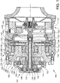
- Figure 1 shows a hub unit 100 comprising an electric machine 102 adapted for producing an input power in order to drive a wheel.
- the hub unit comprises at least two planetary gears 104,106,108 coupled in series between the electric machine 102 and a wheel hub 110.
- the electric machine 102 is arranged axially inwards of the series of planetary gears 104,106,108.
- the hub unit 100 further comprises a gear shifting device 112 for connecting and disconnecting, respectively, one of said planetary gears 104 from being drivingly connected between the electric machine 102 and the wheel hub 110.
- the hub unit 100 comprises three planetary gears 104,106,108 coupled in series between the electric machine 102 and the wheel hub 110.
- upstream and downstream are defined referring to the power transmission path from the electric machine 102 to the wheel hub 110.
- a planet carrier 114 in the upstream planetary gear 104 is rotationally rigidly connected to a sun gear 116 in the downstream planetary gear 106.
- a planetary gear member 114, 116 forms the planet carrier 114 in the upstream planetary gear and the sun gear 116 in the downstream planetary gear.
- the upstream planetary gear 104 is arranged axially outwards of the downstream planetary gear 106.
- the electric machine 102 is arranged axially inwards of the series of planetary gears 104,106,108.
- the power transmission path extends from the electric machine 102 axially outwards to the upstream planetary gear 104 and then axially inwards to the downstream planetary gears 106,108.
- a sun gear 116,118,120 forms an input to each planetary gear 104,106,108 and a planet carrier 114,122,124 forms an output from each planetary gear 104,106,108.
- the wheel hub 110 is rotationally rigidly connected to the planet carrier 124 in the last planetary gear 108 in the series, wherein the wheel hub 110 and the planet carrier form a structure rotating at wheel speed.
- a bearing arrangement 126 rotatably support the wheel hub 110.
- a ring gear 128 in the last planetary gear 108 in the series is stationary.
- the wheel hub and planet carrier structure 110,124 rotating at wheel speed is mounted in the bearing arrangement 126 relative to the ring gear 128. More specifically, the structure 110,124 rotating at wheel speed is mounted in the bearing arrangement 126 radially outside the ring gear 128.
- the bearing arrangement 126 comprises at least one row of balls 130 arranged between races in opposite portions of the structure 110,124 rotating at wheel speed and the ring gear 128.
- the gear shifting device 112 is adapted for connecting and disconnecting, respectively, the upstream (first) planetary gear 104 from being drivingly connected to the wheel hub 110.
- the gear shifting device 112 is adapted to selectively drivingly connect the sun wheel 118 in the upstream (first) planetary gear 104 and the sun wheel 116 of the downstream planetary (second) gear 106 to a drive shaft 132 adapted to transmit power from the electric machine 102.
- a first drive shaft 134 is rotationally rigidly connected to the sun gear 118 in the first planetary gear 104 in the series.
- a second shaft 136 which is arranged co-axially with the first shaft 134, is rotationally rigidly connected to the sun gear 116 in the second planetary gear 106 in the series.
- the gear shifting device 112 comprises means 138 for selectively drivingly connect one of said first and second shaft 134,136 to the drive shaft 132 adapted to transmit power from the electric machine 102.
- the connection means 138 of the gear shifting device 112 comprises a shift sleeve, which is displaceable in an axial direction and comprises portions 140,142 for engaging one of said first and second shaft 134,136 at a time.
- Each of the first and second shaft 134,136 comprises a correspondingly configured engagement portion 141,143 in the form of a flange with splines or other engaging structure.
- the splined flanges 141,143 of the first and second shaft 134,136 is arranged at an axial distance from each other and the shift sleeve is arranged between the splined flanges for engagement with the first shaft 134 in a retracted position and the second shaft 136 in a forwarded position.
- the hub unit 100 comprises a brake 144.
- the brake 144 is adapted to brake the sun gear 120 in the last planetary gear 108.
- the brake 144 is formed by a wet disc brake.
- the brake comprises a brake disc 147 which is rotationally rigidly connected to the sun gear 120.
- the brake 144 further comprises an actuation means 145 in the form of a piston for engaging the brake disc 147 and a return spring member.
- the brake forms an emergency brake and/or an auxiliary brake (the main brake function is achieved via the electric machine).
- a planet carrier 114,122 in an upstream planetary gear see the first and second planetary gears 104,106, is positioned so that a planet wheel supporting pin 146,148 extends from a planet carrier body 150,152 in an axially outwards direction.
- the planet carrier 124 in the third and last (downstream) planetary gear 108 is positioned so that a planet wheel supporting pin 154 extends from a planet carrier body 156 in an axially inwards direction, towards the electric machine 102.
- the planet carrier 124 in the third (and last) planetary gear 108 in the series comprises a portion 127 that extends radially outside the second (upstream) planetary gear 106 and is adapted to be rotationally rigidly connected to the wheel hub 110 (via a bolt connection).
- Figure 2 discloses a frame-steered work machine in the form of a wheel loader 200 having an implement 202 in the form of a bucket.
- the bucket 202 is arranged on a load arm unit 204 for lifting and lowering the bucket 202, and further the bucket 202 can be tilted or pivoted relative to the arm unit 204.
- the wheel loader 200 is provided with a hydraulic system comprising at least one hydraulic pump (not shown) and working cylinders 205a,205b,206 for the operation of the arm unit 204 and the bucket 202.
- the hydraulic system comprises working cylinders 207a,207b for turning the wheel loader by means of relative movement of a front body 208 and a rear body 209.
- a front body 208 and a rear body 209.
- two working cylinders known as lifting cylinders 205a,205b are arranged for lifting and lowering the arm unit 204, and a further working cylinder known as tilting cylinder 206 is arranged for tilting-in or tilting-out the bucket 202 relative to the arm unit 204.
- two working cylinders known as the steering cylinders 207a,207b are arranged for steering the wheel loader 200.
- the wheel loader comprises a plurality of driving wheels 210a,210b,212a,212b.
- the above described hub unit 100 is arranged at each of said driving wheels 210a,210b, 212a,212b for individually driving each wheel.
- FIG. 3 schematically discloses a wheel axle 300 of the wheel loader 200.
- a pair of interconnected transverse drive shafts 302a,302b extends in opposite directions, each of which drives one of said wheels 210a,210b.
- a hub unit 100a,100b is indicated at each wheel 210a,210b.
- a clutch 304 is adapted to engage and disengage, respectively the transverse drive shafts 302a,302b to being rotationally rigidly connected to each other.
- the hub units 210a,210b at opposite wheels are interconnected via the transverse drive shafts 302a,302b. In this way, one of the hub units 100a can support the other hub unit 100b in providing power for driving its associated wheel 210b.
- first wheel 210a has no grip (i.e free slip) and the other wheel 210b has a firm grip (i.e no or little slip).
- the wheel 210b with a firm grip may be able to transmit more torque than the associated hub unit 100b can supply.
- the first hub unit 100a can then be controlled to supply the excess torque.
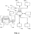
- FIG. 4 schematically discloses a control system 410 of the work machine 200.
- the control system 410 comprises an electric power generating means 402, which is connected to the electric machines in the hub units 100a,100b,400a,400b for supplying power to the electric machines.
- the control system 410 further comprises an electric energy storage means 404, which is connected to the electric machines in the hub units 100a,100b, 400a,400b for an exchange of electric energy.
- a control unit 408 is arranged for controlling operation of the power communication to and from the electric machines in the hub units 100a,100b,400a,400b via a an intersection 406.
- the electric power generating means 402 comprises an internal combustion engine 409 provided with an electric generator 412.
- the electric power generating means 200 can be designed in many different ways as long as it is able to provide electricity.
- One option is to use a fuel cell for providing electricity.
- Another example is to use a gas turbine provided with an electric generator.
- the electric energy storage means 404 is adapted for storing energy from the electric power generating means 402 and/or from the electric machines in the hub units 100a,100b,400a,400b. This electric energy storage means 404 is then used to provide electricity to the electric machines in the hub units 100a,100b,400a,400b.
- a hydraulic system 414 comprising further electric machines (not shown) for driving pumps is operatively connected to the power generating means 402.
- the control unit 408 is configured for controlling an exchange of electric energy between the electric machines 100a,100b,400a,400b, the hydraulic system 414 and the electric energy storage means 404.
- energy may be recuperated by the electric machines 100a,100b,400a,400b during retardation, and by the hydraulic system 414 during lowering and retarding a load.
- the recuperated energy may be stored in the electric energy storage means 404 for use in a later acceleration or lifting action.
- a second embodiment of the hub unit 500 is shown in the hub units illustrated in Figs 5-13 are merely illustrative and do not fall within the claimed scope of protection.
- a hub unit 500 is shown in figure 5 .
- the hub unit 500 differs from the first embodiment of the hub unit 100 in the design of the gear shifting device 502.
- the gear shifting device 502 comprises connection means in the form of two sets of clutch discs 504, 506, which are adapted for engaging one of said first shaft 508 and second shaft 510 at a time.
- the first clutch disc set 504 comprises at least one rotation disc, which is rotationally rigidly connected to the second shaft 510 and the second clutch disc set 506 comprises at least one rotation disc, which is rotationally rigidly connected to the first shaft 508.
- the electric machine 502 comprises a rotor 512.
- the clutch disc sets 504,506 are arranged on opposite sides of the rotor 512 for engaging the rotor one at a time.
- a spring member 514 is adapted to effect the first disc set 504 for engagement with the rotor 512.
- a brake actuating means in the form of a piston 516 is arranged for compressing the second disc set 506 for engagement with the rotor.
- a force transmitting member 518 in the form of at least one rigid rod is operatively arranged between the brake actuating means 516 and the spring member 514 such that the spring effected disc set is released when the other disc set is in a compressed state.
- a plurality of circumferentially spaced rods is arranged between the brake actuating means 516 and the spring member 514.
- a third hub unit 600 is shown in figure 6 .
- the third hub unit 600 differs from the second hub unit 500 in that the wet disc brake 644 is adapted to brake a part 624 rotating at wheel speed instead of the sun gear 120 in the last planetary gear. More specifically, the wheel speed part 624 is rotationally rigidly connected to the wheel hub 610. More particularly, the wheel speed part 624 forms part of the planet carrier in the last planetary gear step.
- a planet wheel supporting pin 646 extends from a planet carrier body in the axial direction and the wet disc brake is positioned on an opposite side of the planet wheel relative to the planet carrier body. The wet disc brake is adapted to engage with the axially extending planet wheel supporting pin 646 in order to brake the rotation of the planet carrier 624 and thereby also the wheel hub 610.
- the brake 644 comprises a first set of brake discs, which are rotationally rigidly connected to the planet wheel supporting pin 646, and a second set of brake discs, which are arranged rotationally rigidly connected to a stationary housing, in the form of an axle housing.
- the brake discs in the second set consequently consist of so-called stationary discs.
- the brake discs are arranged so that every other brake disc forms part of the first set and every second brake disc forms part of the second set.
- the brake discs in the first set are displaceable along the planet wheel supporting pin 646 in the axial direction.
- the brake discs in the second set are arranged in the housing so that they are also displaceable in the axial direction.
- a fourth hub unit 700 is shown in figure 7 .
- the first planetary gear 704 is arranged inside the second and third planetary gears 706,708 in the axial direction. More specifically, the first planetary gear 704 is arranged inside a casing of the electric machine 702.
- a rotor 712 of the electric machine 702 is rotationally rigidly connected to a sun wheel 718 of the first planetary gear 704 via a tubular shaft 717 which is co-axial with a drive shaft 736 connected to the second planetary gear 706.
- a gear shifting device 713 is adapted to connect and disconnect, respectively the first planetary gear 704 from being drivingly connected to the electric machine. More specifically, the gear shifting device 713 is adapted to connect and disconnect, respectively an output of the first planetary gear 704 to the drive shaft 736, which is adapted to drive a sun wheel 716 in the second planetary gear 706. Said output of the first planetary gear 704 is formed by the planet carrier.
- the gear shifting device 713 comprises connection means in the form of two sets of clutch discs 705,707, which are adapted for rotationally connecting one of said planet carrier and the tubular shaft 717 at a time to the drive shaft 736.
- connection means in the form of two sets of clutch discs 705,707, which are adapted for rotationally connecting one of said planet carrier and the tubular shaft 717 at a time to the drive shaft 736.
- a low gear is achieved when a first set of clutch discs 705 connects the planet carrier to the sun gear 716 of the second planetary gear (via the drive shaft 736).
- a high gear is achieved when a second set of clutch discs 707 connects the rotor 712 of the electric machine 702 via the sun gear 718 to the sun gear 716 of the second planetary gear (via the drive shaft 736).
- the gear shifting device 713 comprises a disc carrier 715, which is rotationally rigidly connected to the drive shaft 736 and carries two sets of clutch discs, wherein each one of these clutch disc
- One advantage with positioning the first planetary gear 704 in direct vicinity of the electric machine 702 is that the inner drive shaft 736 will rotate at a comparatively low speed when the high gear is engaged. This leads to an increased efficiency with regard to losses, that the associated bearings are less subjected to stresses and to a good controllability of the clutch.
- a further advantage associated with the fourth hub unit 700 is that positioning the first planetary gear 704 inside a casing of the electric machine 702 creates conditions for a more compact design.
- a fifth hub unit 800 is shown in figure 8 .
- the fifth hub unit differs from the fourth hub unit in the position and arrangement of the electric machine 802.
- the electric machine 802 is turned relative to the electric machine 702 so that the rotor 812 is arranged axially outside the first planetary gear 804. More specifically, the electric machine 802 change places with the gear shifting device 813 with regard to the first planetary gear 804.
- the rotor 812 is rotationally rigidly connected to the sun wheel of the first planetary gear 804 via a drive shaft 817.
- the second set of clutch discs 807 in the gear shifting device 813 connects the rotor 812 of the electric machine 802 via the drive shaft 817 to the drive shaft 836, which is connected to the second planetary gear 806.
- a sixth hub unit 900 is shown in figure 9 .
- the sixth hub unit differs from the fourth hub unit in the position and arrangement of the gear shifting device 913.
- the rotor 912 is rotationally rigidly connected to the sun wheel of the first planetary gear 904 via a tubular shaft 917.
- a first set of clutch discs 905 in the gear shifting device 913 connects a ring gear 909 to a stationary casing 911.
- a second set of clutch discs 907 in the gear shifting device 913 connects the rotor 912 of the electric machine 902 via the tubular drive shaft 917 to the drive shaft 936, which is connected to the second planetary gear 906.
- the first set of clutch discs 905 forms a brake.
- One advantage with the feature that the first set of clutch discs 905 forms a brake is that oil pressure and force for application of the clutch can be applied via stationary means. In other words, oil pressure and force does not have to be applied in a rotary manner.
- a further advantage with the design of the brake 905 is that it creates conditions for carrying a reduced torque.
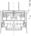
- a seventh hub unit 1000 is shown in figure 10 .
- the seventh hub unit differs from the sixth hub unit in the position and arrangement of the electric machine 1002.
- the electric machine 1002 is turned relative to the electric machine 902 in a similar manner as has been described above for the fifth embodiment.
- An eighth hub unit 1100 is shown in figure 11 .
- the eighth hub unit differs from the sixth hub unit in the bearing arrangement 1126.
- the bearing arrangement 1126 comprises two axially spaced roller bearings 1128,1130.
- the wheel hub 1110 is mounted by means of the roller bearings 1128,1130 to a static housing 1132.
- a wet disc brake 1144 is adapted to brake a part 1124 rotating at wheel speed. More specifically, the wheel speed part 1124 is rotationally rigidly connected to the wheel hub 1110.
- One advantage with this type of bearing arrangement is that it creates a sufficient space for a wet wheel speed brake.
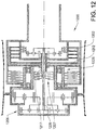
- a ninth hub unit 1200 is shown in figure 12 .
- the ninth hub unit differs from the eighth hub unit in the position of the second set of clutch discs 1207.
- the second set of clutch discs 1207 in the gear shifting device connects the rotor 1212 of the electric machine 1202 via a tubular drive shaft 1217 to the drive shaft 1236, which is connected to the second planetary gear 1206.
- the second set of clutch discs 1207 is positioned axially outside the electric machine 1202. More specifically, the second set of clutch discs 1207 is positioned radially inside the bearing arrangement 1226.
- a tenth hub unit 1300 is shown in figure 13 .
- the tenth hub unit differs from the eighth hub unit in that a ring gear 1309 of the last (third) planetary gear 1308 is rotationally rigidly connected to the wheel hub 1310 for driving the hub.
- a planet carrier 1324 of the last planetary gear 1308 is rotationally rigidly connected to a stationary casing 1332.
- the wheel hub 1310 is mounted to the stationary casing 1332 via a pair of axially spaced roller bearings. More specifically, the wheel hub 1310 is rotationally rigidly connected to a tubular part 1311, which is mounted to the stationary casing 1332 via the roller bearings.
- a first clutch actuating means is arranged for compressing said first disc set 504 for engagement with the rotor
- a second clutch actuating means is arranged for compressing the second disc set 506 for engagement with the rotor.
- the first and second clutch actuating means are in that case arranged to work in opposite direction in order to compress its associated disc set 504,506.
- the gear shifting device is adapted to achieve a braking effect when both sets of clutch discs engage the rotor at the same time.
- wheels is meant to comprise vehicle wheels for direct engagement with the ground as well as vehicle wheels for driving a ground engaging member, such as tracks, crawlers or similar.
- the electric machine can be used as a brake during a braking operation of the working machine, such as a wheel loader, and at the same time function as a generator for recuperating energy.
- the energy from the electric power generating motor can be directly supplied to the electric machine and the hydraulic system or stored in the electric energy storage means, such as a battery or super capacitor, to be used later on.
- the upstream planetary gear may be arranged axially inwards of the downstream planetary gear.
- the planetary gears may be arranged so that the power transmission path from the electric machine to the wheel hub extends axially outwards from the electric machine, to the upstream (first) planetary gear, further axially outwards to the second and third planetary gears, and further axially outwards to the wheel hub.
- two wheel bearings may be arranged at an axial distance.
- the brake may be configured to act as a service brake and/or parking brake.
Landscapes
- Engineering & Computer Science (AREA)
- Mechanical Engineering (AREA)
- Chemical & Material Sciences (AREA)
- Combustion & Propulsion (AREA)
- Transportation (AREA)
- General Engineering & Computer Science (AREA)
- Retarders (AREA)
- Hybrid Electric Vehicles (AREA)
- Arrangement Or Mounting Of Propulsion Units For Vehicles (AREA)
Claims (16)
- Unité de moyeu (100) comprenant un moyeu de roue (110) et une machine électrique (102) adaptée pour entraîner une roue, où l'unité de moyeu (100) comprend au moins deux engrenages planétaires (104, 106, 108) couplés en série entre la machine électrique (102) et le moyeu de roue (110), et un dispositif de changement de vitesse (112, 502) pour connecter et déconnecter, respectivement, l'un desdits engrenages planétaires à/de l'état dans lequel il est connecté en entraînement à la machine électrique,
dans laquelle un premier arbre d'entraînement (134) est adapté pour transmettre la puissance à un premier engrenage planétaire (104) dans la série, où un deuxième arbre (136), qui est agencé coaxialement avec le premier arbre d'entraînement (134), est adapté pour transmettre la puissance à un deuxième engrenage planétaire (106) dans la série, caractérisée en ce que ce que le dispositif de changement de vitesse (112) comprend un moyen pour connecter en entraînement de manière sélective l'un desdits premier et deuxième arbre à un arbre d'entraînement (132) adapté pour transmettre la puissance de la machine électrique (102), et en ce que le moyen de connexion du dispositif de changement de vitesse comprend un manchon à décalage (138) qui peut être déplacé dans une direction axiale et comprend des parties (140, 142) pour s'engager avec l'un desdits premier et deuxième arbres à la fois. - Unité de moyeu selon la revendication 1, caractérisée en ce qu'un élément d'engrenage planétaire forme un porte-satellites (114, 122) dans un engrenage planétaire amont et un planétaire (116, 120) dans un engrenage planétaire aval.
- Unité de moyeu selon la revendication 1 ou 2, caractérisée en ce que l'unité de moyeu comprend trois engrenages planétaires (104, 106, 108) couplés en série entre la machine électrique (102) et le moyeu de roue (110).
- Unité de moyeu selon l'une des revendications précédentes, caractérisée en ce que la machine électrique (102) est agencée axialement vers l'intérieur d'au moins l'un des engrenages planétaires (104, 106, 108) par rapport au moyeu de roue (110).
- Unité de moyeu selon l'une des revendications précédentes, caractérisée en ce qu'au moins un engrenage planétaire amont (104) est agencé axialement vers l'extérieur d'un engrenage planétaire aval (106) par rapport au moyeu de roue (110).
- Unité de moyeu selon l'une des revendications précédentes, caractérisée en ce qu'un planétaire (116, 118, 120) forme une entrée à chaque engrenage planétaire (104, 106, 108).
- Unité de moyeu selon l'une des revendications précédentes, caractérisée en ce que le dispositif de changement de vitesse (112) est adapté pour connecter et déconnecter, respectivement, un engrenage planétaire amont (104) de l'état dans lequel il est connecté en entraînement au moyeu de roue (110).
- Unité de moyeu selon l'une des revendications précédentes, caractérisée en ce que le dispositif de changement de vitesse (112) est adapté pour connecter en entraînement de manière sélective soit un élément d'engrenage planétaire d'entrée (118) dans un engrenage planétaire amont (104) ou un élément d'engrenage planétaire d'entrée (116) d'un engrenage planétaire aval (106) à un arbre d'entraînement (132) adapté pour transmettre la puissance de la machine électrique.
- Unité de moyeu selon la revendication 8, caractérisée en ce que le premier arbre d'entraînement (134) est connecté rigidement en rotation à un planétaire (118) dans le premier engrenage planétaire (104) dans la série, et en ce que le deuxième arbre (136) est connecté rigidement en rotation à un planétaire (116) dans le deuxième engrenage planétaire (106) dans la série.
- Unité de moyeu selon l'une des revendications précédentes, caractérisée en ce qu'elle comprend un frein (144).
- Unité de moyeu selon la revendication 10, caractérisée en ce que le frein (144) est adapté pour freiner un élément d'engrenage planétaire (120) dans un dernier engrenage planétaire (108).
- Unité de moyeu selon l'une des revendications 10 à 11, caractérisée en ce que le frein (144) est adapté pour freiner un planétaire (120) dans l'un des engrenages planétaires.
- Unité de moyeu selon l'une des revendications précédentes, caractérisée en ce que le moyeu de roue (110) est connecté rigidement en rotation à un élément d'engrenage planétaire (124) dans un dernier engrenage planétaire (108) dans la série, où le moyeu de roue et le porte-satellites forment une structure tournant à la vitesse de roue.
- Unité de moyeu selon l'une des revendications précédentes, caractérisée en ce qu'un élément d'engrenage planétaire de sortie (124) dans un dernier engrenage planétaire (108) dans la série comprend une partie (127) qui s'étend radialement à l'extérieur d'un engrenage planétaire amont (106) et est adapté pour être connecté rigidement en rotation au moyeu de roue (110).
- Groupe motopropulseur pour un véhicule (200), caractérisé en ce qu'il comprend une pluralité de roues d'entraînement (210a, 210b, 212a, 212b), où une unité de moyeu (100) selon l'une des revendications précédentes est agencée au niveau d'au moins l'une desdites roues pour entraîner individuellement la roue associée.
- Machine de travail caractérisée en ce qu'elle comprend un groupe motopropulseur selon la revendication 15.
Applications Claiming Priority (1)
| Application Number | Priority Date | Filing Date | Title |
|---|---|---|---|
| PCT/SE2006/001393 WO2008069707A1 (fr) | 2006-12-06 | 2006-12-06 | Unité de moyeu et transmission pour un véhicule |
Publications (3)
| Publication Number | Publication Date |
|---|---|
| EP2099633A1 EP2099633A1 (fr) | 2009-09-16 |
| EP2099633A4 EP2099633A4 (fr) | 2011-07-20 |
| EP2099633B1 true EP2099633B1 (fr) | 2016-03-30 |
Family
ID=39492449
Family Applications (1)
| Application Number | Title | Priority Date | Filing Date |
|---|---|---|---|
| EP06824519.0A Active EP2099633B1 (fr) | 2006-12-06 | 2006-12-06 | Unité de moyeu et transmission pour un véhicule |
Country Status (4)
| Country | Link |
|---|---|
| US (2) | US8505658B2 (fr) |
| EP (1) | EP2099633B1 (fr) |
| CN (1) | CN101588938B (fr) |
| WO (1) | WO2008069707A1 (fr) |
Families Citing this family (26)
| Publication number | Priority date | Publication date | Assignee | Title |
|---|---|---|---|---|
| SE534622C2 (sv) * | 2009-07-07 | 2011-10-25 | Bae Systems Haegglunds Ab | Midjestyrt bandfordon |
| CN101830172A (zh) * | 2010-05-12 | 2010-09-15 | 湖北车桥有限公司 | 轮边电动车桥 |
| CN102720810B (zh) * | 2011-03-30 | 2016-03-02 | 比亚迪股份有限公司 | 自动变速器、包含该自动变速器的车辆及其换挡方法 |
| JP5728272B2 (ja) * | 2011-03-31 | 2015-06-03 | 本田技研工業株式会社 | 電動車両 |
| EP2620311A1 (fr) * | 2012-01-30 | 2013-07-31 | FPT Industrial S.p.A. | Ensemble d'arbre de roue destiné à un véhicule industriel lourd et véhicule industriel lourd comprenant un tel ensemble d'arbre de roue |
| WO2014063729A1 (fr) * | 2012-10-24 | 2014-05-01 | Zollern Gmbh & Co.Kg | Transmission dotée d'un frein |
| US9062744B2 (en) * | 2013-03-13 | 2015-06-23 | American Axle & Manufacturing, Inc. | Two-speed drive module |
| CN103395361A (zh) * | 2013-08-06 | 2013-11-20 | 河北格洛斯节能设备科技有限公司 | 轮毂式内转子电动轮 |
| US10214094B2 (en) | 2013-08-19 | 2019-02-26 | Lappeenrannan Teknillinen Yliopisto | Electrical motor construction provided with a planetary gear system |
| CN104590001B (zh) * | 2014-11-27 | 2016-04-06 | 东风汽车公司 | 一种一体化轮毂电机驱动单元 |
| WO2016119015A1 (fr) * | 2015-01-28 | 2016-08-04 | Cameron Clark Anthony | Ensemble roue, procédé permettant de commander le mouvement d'un objet et dispositif de stockage et de transport de bâton de golf |
| US9511661B2 (en) | 2015-03-12 | 2016-12-06 | Deere & Company | Driven wheel unit including an axially compact two-speed planetary gear drive assembly |
| US9562603B2 (en) * | 2015-06-29 | 2017-02-07 | Deere & Company | Drive assembly with a rotating housing attached to an output interface |
| US9638310B2 (en) | 2015-06-29 | 2017-05-02 | Deere & Company | Drive assembly with a rotating housing attached to an output interface |
| US9618084B2 (en) | 2015-08-25 | 2017-04-11 | Deere & Company | Compact planetary arrangement for final drive |
| CN108473052B (zh) | 2015-12-22 | 2022-04-19 | 沃尔沃建筑设备公司 | 轮毂单元 |
| US10107363B2 (en) * | 2016-01-28 | 2018-10-23 | Deere & Company | Compact multi-speed planetary drive assembly |
| US10214101B2 (en) * | 2016-04-27 | 2019-02-26 | Deere & Company | Work vehicle drive assembly |
| CN107599824B (zh) * | 2017-08-15 | 2019-07-26 | 湖北航天技术研究院特种车辆技术中心 | 一种低速大扭矩单级减速器电动轮 |
| US11345232B2 (en) | 2018-09-06 | 2022-05-31 | Volvo Construction Equipment Ab | Wheel hub arrangement for a driving wheel of a vehicle |
| EP3849835B1 (fr) * | 2018-09-11 | 2022-09-28 | Volvo Construction Equipment AB | Système d'entraînement de moyeu de roue |
| CN109017271B (zh) * | 2018-10-10 | 2024-01-19 | 浙江盘毂动力科技有限公司 | 一种电动汽车及其动力驱动装置 |
| IT201900000112A1 (it) | 2019-01-07 | 2020-07-07 | Invaction S R L | Assieme per un veicolo e veicolo comprendente detto assieme |
| EP3789209B1 (fr) * | 2019-09-05 | 2023-06-07 | KNORR-BREMSE Systeme für Nutzfahrzeuge GmbH | Système de freinage pour essieux à deux pneus |
| FI130272B (en) | 2020-02-11 | 2023-05-30 | Lappeenrannan Lahden Teknillinen Yliopisto Lut | Electromechanical device |
| CN112026513B (zh) * | 2020-09-07 | 2022-02-15 | 中国第一汽车股份有限公司 | 一种断开装置及同轴电驱动系统 |
Family Cites Families (21)
| Publication number | Priority date | Publication date | Assignee | Title |
|---|---|---|---|---|
| US1832598A (en) * | 1927-08-23 | 1931-11-17 | George L Weber | Planetary gear wheel for power vehicles |
| GB1347192A (en) * | 1972-04-07 | 1974-02-27 | Zahnradfabrik Friedrichshafen | Indivicual wheel drives for wheels |
| US3866490A (en) * | 1974-02-19 | 1975-02-18 | Orshansky Transmission Corp | Split power transmission |
| US3897843A (en) * | 1973-11-29 | 1975-08-05 | Gen Electric | Electric motorized wheel |
| DE2842076C2 (de) | 1978-09-27 | 1984-09-06 | Siemens AG, 1000 Berlin und 8000 München | Einzelradantrieb für Fahrzeuge |
| US4330045A (en) * | 1979-09-14 | 1982-05-18 | Reliance Electric Company | Vehicle wheel mechanism |
| JPS56154329A (en) * | 1980-04-25 | 1981-11-28 | Nissan Motor Co Ltd | Four-wheel-drive vehicle |
| DE3069495D1 (en) * | 1980-06-17 | 1984-11-29 | Acec | Geared-motor with brake |
| US4418777A (en) * | 1981-09-11 | 1983-12-06 | Ford Motor Company | Transmission lubrication and motor cooling system |
| US4602525A (en) * | 1984-04-27 | 1986-07-29 | Aisin Warner Kabushiki Kaisha | Continuously variable speed transmission for a vehicle having a forward-reverse changeover mechanism |
| CA1279582C (fr) * | 1986-01-29 | 1991-01-29 | Katsuhiko Iijima | Entrainement electrique de roues |
| US4930590A (en) * | 1989-05-11 | 1990-06-05 | Deere & Company | Motor and transmission assembly |
| US5427196A (en) * | 1992-07-08 | 1995-06-27 | Kabushikikaisha Equos Research | Electric motor drive system |
| DE19510914C2 (de) * | 1995-03-24 | 2003-10-30 | Linde Ag | Hydromechanisches Antriebsaggregat |
| US5813488A (en) * | 1996-06-14 | 1998-09-29 | Deere & Company | Electric wheel drive for a utility vehicle |
| DE19850606B4 (de) * | 1998-11-03 | 2010-01-21 | Renk Aktiengesellschaft | Kettenfahrzeug |
| US6358173B1 (en) * | 2000-06-12 | 2002-03-19 | General Motors Corporation | Two-mode, compound-split, electro-mechanical vehicular transmission having significantly reduced vibrations |
| JP4460145B2 (ja) * | 2000-08-30 | 2010-05-12 | 本田技研工業株式会社 | 電気自動車におけるインホイール変速機の制御装置 |
| US6648785B2 (en) * | 2001-12-05 | 2003-11-18 | New Venture Gear, Inc. | Transfer case for hybrid vehicle |
| US6663526B2 (en) * | 2002-01-08 | 2003-12-16 | Ford Global Technologies, Llc | Transmission isolation assembly |
| GB2389827B (en) * | 2002-06-18 | 2005-12-14 | Magnetic Systems Technology Lt | Hub drive system |
-
2006
- 2006-12-06 US US12/518,100 patent/US8505658B2/en active Active
- 2006-12-06 CN CN2006800565585A patent/CN101588938B/zh active Active
- 2006-12-06 WO PCT/SE2006/001393 patent/WO2008069707A1/fr active Application Filing
- 2006-12-06 EP EP06824519.0A patent/EP2099633B1/fr active Active
-
2013
- 2013-05-18 US US13/897,380 patent/US8746385B2/en active Active
Also Published As
| Publication number | Publication date |
|---|---|
| CN101588938A (zh) | 2009-11-25 |
| US8505658B2 (en) | 2013-08-13 |
| US20100294576A1 (en) | 2010-11-25 |
| US20130252775A1 (en) | 2013-09-26 |
| CN101588938B (zh) | 2013-05-22 |
| EP2099633A1 (fr) | 2009-09-16 |
| US8746385B2 (en) | 2014-06-10 |
| WO2008069707A1 (fr) | 2008-06-12 |
| EP2099633A4 (fr) | 2011-07-20 |
Similar Documents
| Publication | Publication Date | Title |
|---|---|---|
| EP2099633B1 (fr) | Unité de moyeu et transmission pour un véhicule | |
| JP2776932B2 (ja) | 車両用駆動装置 | |
| EP0479800B1 (fr) | Train épicycloidal | |
| EP2414184B1 (fr) | Boîte-pont d' entraînement électrique à deux vitesses | |
| US9303745B2 (en) | Multi-speed transaxle for electric and hybrid vehicle application | |
| US11498410B2 (en) | Powered axle for dual wheel work vehicle | |
| US8702560B2 (en) | Construction machine | |
| EP3863877B1 (fr) | Transmission de véhicule utilitaire | |
| WO2015099600A1 (fr) | Procédé permettant d'alimenter les appareils électriques d'un véhicule | |
| US20170120739A1 (en) | Utility vehicle, in particular motor truck, having at least one double-axle unit | |
| EP3086965B1 (fr) | Système de propulsion pour un véhicule | |
| EP2594825A1 (fr) | Dispositif de transmission de puissance | |
| WO2014003668A1 (fr) | Procédé pour l'avancement d'un véhicule hybride | |
| EP1910121B1 (fr) | Transmission planetaire, dispositif d' entrainement comprenant la transmission planetaire et vehicule comprenant le dispositif d' entrainement | |
| CA2396461C (fr) | Entrainement d'essieu a planetaire a double demultiplication | |
| EP3086968B1 (fr) | Système de propulsion pour un véhicule | |
| US8353804B2 (en) | Hybrid transmission and method of use | |
| EP1899619B1 (fr) | Transmission planétaire, dispositif d entraînement et véhicule utilitaire | |
| WO2018202856A1 (fr) | Machine de travail | |
| US20240034144A1 (en) | Hydromechanical systems and devices | |
| JPH0550864A (ja) | 車両用電動装置 |
Legal Events
| Date | Code | Title | Description |
|---|---|---|---|
| PUAI | Public reference made under article 153(3) epc to a published international application that has entered the european phase |
Free format text: ORIGINAL CODE: 0009012 |
|
| 17P | Request for examination filed |
Effective date: 20090706 |
|
| AK | Designated contracting states |
Kind code of ref document: A1 Designated state(s): AT BE BG CH CY CZ DE DK EE ES FI FR GB GR HU IE IS IT LI LT LU LV MC NL PL PT RO SE SI SK TR |
|
| DAX | Request for extension of the european patent (deleted) | ||
| A4 | Supplementary search report drawn up and despatched |
Effective date: 20110622 |
|
| RIC1 | Information provided on ipc code assigned before grant |
Ipc: F16D 11/14 20060101ALI20110616BHEP Ipc: B60K 17/14 20060101AFI20080624BHEP Ipc: B60K 7/00 20060101ALI20110616BHEP Ipc: B60K 17/356 20060101ALI20110616BHEP |
|
| 17Q | First examination report despatched |
Effective date: 20130517 |
|
| REG | Reference to a national code |
Ref country code: DE Ref legal event code: R079 Ref document number: 602006048482 Country of ref document: DE Free format text: PREVIOUS MAIN CLASS: B60K0017140000 Ipc: B60K0007000000 |
|
| RIC1 | Information provided on ipc code assigned before grant |
Ipc: B60K 17/356 20060101ALI20150305BHEP Ipc: B60K 7/00 20060101AFI20150305BHEP Ipc: B60K 17/04 20060101ALI20150305BHEP |
|
| GRAP | Despatch of communication of intention to grant a patent |
Free format text: ORIGINAL CODE: EPIDOSNIGR1 |
|
| INTG | Intention to grant announced |
Effective date: 20150507 |
|
| GRAP | Despatch of communication of intention to grant a patent |
Free format text: ORIGINAL CODE: EPIDOSNIGR1 |
|
| INTG | Intention to grant announced |
Effective date: 20151007 |
|
| GRAS | Grant fee paid |
Free format text: ORIGINAL CODE: EPIDOSNIGR3 |
|
| GRAA | (expected) grant |
Free format text: ORIGINAL CODE: 0009210 |
|
| AK | Designated contracting states |
Kind code of ref document: B1 Designated state(s): AT BE BG CH CY CZ DE DK EE ES FI FR GB GR HU IE IS IT LI LT LU LV MC NL PL PT RO SE SI SK TR |
|
| REG | Reference to a national code |
Ref country code: GB Ref legal event code: FG4D |
|
| REG | Reference to a national code |
Ref country code: CH Ref legal event code: EP |
|
| REG | Reference to a national code |
Ref country code: AT Ref legal event code: REF Ref document number: 784959 Country of ref document: AT Kind code of ref document: T Effective date: 20160415 |
|
| REG | Reference to a national code |
Ref country code: IE Ref legal event code: FG4D |
|
| REG | Reference to a national code |
Ref country code: DE Ref legal event code: R096 Ref document number: 602006048482 Country of ref document: DE |
|
| REG | Reference to a national code |
Ref country code: LT Ref legal event code: MG4D |
|
| PG25 | Lapsed in a contracting state [announced via postgrant information from national office to epo] |
Ref country code: FI Free format text: LAPSE BECAUSE OF FAILURE TO SUBMIT A TRANSLATION OF THE DESCRIPTION OR TO PAY THE FEE WITHIN THE PRESCRIBED TIME-LIMIT Effective date: 20160330 Ref country code: GR Free format text: LAPSE BECAUSE OF FAILURE TO SUBMIT A TRANSLATION OF THE DESCRIPTION OR TO PAY THE FEE WITHIN THE PRESCRIBED TIME-LIMIT Effective date: 20160701 |
|
| REG | Reference to a national code |
Ref country code: NL Ref legal event code: MP Effective date: 20160330 |
|
| REG | Reference to a national code |
Ref country code: AT Ref legal event code: MK05 Ref document number: 784959 Country of ref document: AT Kind code of ref document: T Effective date: 20160330 |
|
| PG25 | Lapsed in a contracting state [announced via postgrant information from national office to epo] |
Ref country code: LT Free format text: LAPSE BECAUSE OF FAILURE TO SUBMIT A TRANSLATION OF THE DESCRIPTION OR TO PAY THE FEE WITHIN THE PRESCRIBED TIME-LIMIT Effective date: 20160330 Ref country code: LV Free format text: LAPSE BECAUSE OF FAILURE TO SUBMIT A TRANSLATION OF THE DESCRIPTION OR TO PAY THE FEE WITHIN THE PRESCRIBED TIME-LIMIT Effective date: 20160330 Ref country code: SE Free format text: LAPSE BECAUSE OF FAILURE TO SUBMIT A TRANSLATION OF THE DESCRIPTION OR TO PAY THE FEE WITHIN THE PRESCRIBED TIME-LIMIT Effective date: 20160330 |
|
| PG25 | Lapsed in a contracting state [announced via postgrant information from national office to epo] |
Ref country code: NL Free format text: LAPSE BECAUSE OF FAILURE TO SUBMIT A TRANSLATION OF THE DESCRIPTION OR TO PAY THE FEE WITHIN THE PRESCRIBED TIME-LIMIT Effective date: 20160330 |
|
| PG25 | Lapsed in a contracting state [announced via postgrant information from national office to epo] |
Ref country code: PL Free format text: LAPSE BECAUSE OF FAILURE TO SUBMIT A TRANSLATION OF THE DESCRIPTION OR TO PAY THE FEE WITHIN THE PRESCRIBED TIME-LIMIT Effective date: 20160330 Ref country code: EE Free format text: LAPSE BECAUSE OF FAILURE TO SUBMIT A TRANSLATION OF THE DESCRIPTION OR TO PAY THE FEE WITHIN THE PRESCRIBED TIME-LIMIT Effective date: 20160330 Ref country code: IS Free format text: LAPSE BECAUSE OF FAILURE TO SUBMIT A TRANSLATION OF THE DESCRIPTION OR TO PAY THE FEE WITHIN THE PRESCRIBED TIME-LIMIT Effective date: 20160730 |
|
| PG25 | Lapsed in a contracting state [announced via postgrant information from national office to epo] |
Ref country code: CZ Free format text: LAPSE BECAUSE OF FAILURE TO SUBMIT A TRANSLATION OF THE DESCRIPTION OR TO PAY THE FEE WITHIN THE PRESCRIBED TIME-LIMIT Effective date: 20160330 Ref country code: AT Free format text: LAPSE BECAUSE OF FAILURE TO SUBMIT A TRANSLATION OF THE DESCRIPTION OR TO PAY THE FEE WITHIN THE PRESCRIBED TIME-LIMIT Effective date: 20160330 Ref country code: ES Free format text: LAPSE BECAUSE OF FAILURE TO SUBMIT A TRANSLATION OF THE DESCRIPTION OR TO PAY THE FEE WITHIN THE PRESCRIBED TIME-LIMIT Effective date: 20160330 Ref country code: RO Free format text: LAPSE BECAUSE OF FAILURE TO SUBMIT A TRANSLATION OF THE DESCRIPTION OR TO PAY THE FEE WITHIN THE PRESCRIBED TIME-LIMIT Effective date: 20160330 Ref country code: SK Free format text: LAPSE BECAUSE OF FAILURE TO SUBMIT A TRANSLATION OF THE DESCRIPTION OR TO PAY THE FEE WITHIN THE PRESCRIBED TIME-LIMIT Effective date: 20160330 Ref country code: PT Free format text: LAPSE BECAUSE OF FAILURE TO SUBMIT A TRANSLATION OF THE DESCRIPTION OR TO PAY THE FEE WITHIN THE PRESCRIBED TIME-LIMIT Effective date: 20160801 |
|
| PG25 | Lapsed in a contracting state [announced via postgrant information from national office to epo] |
Ref country code: BE Free format text: LAPSE BECAUSE OF FAILURE TO SUBMIT A TRANSLATION OF THE DESCRIPTION OR TO PAY THE FEE WITHIN THE PRESCRIBED TIME-LIMIT Effective date: 20160330 Ref country code: IT Free format text: LAPSE BECAUSE OF FAILURE TO SUBMIT A TRANSLATION OF THE DESCRIPTION OR TO PAY THE FEE WITHIN THE PRESCRIBED TIME-LIMIT Effective date: 20160330 |
|
| REG | Reference to a national code |
Ref country code: DE Ref legal event code: R097 Ref document number: 602006048482 Country of ref document: DE |
|
| PG25 | Lapsed in a contracting state [announced via postgrant information from national office to epo] |
Ref country code: DK Free format text: LAPSE BECAUSE OF FAILURE TO SUBMIT A TRANSLATION OF THE DESCRIPTION OR TO PAY THE FEE WITHIN THE PRESCRIBED TIME-LIMIT Effective date: 20160330 |
|
| PLBE | No opposition filed within time limit |
Free format text: ORIGINAL CODE: 0009261 |
|
| STAA | Information on the status of an ep patent application or granted ep patent |
Free format text: STATUS: NO OPPOSITION FILED WITHIN TIME LIMIT |
|
| 26N | No opposition filed |
Effective date: 20170103 |
|
| PG25 | Lapsed in a contracting state [announced via postgrant information from national office to epo] |
Ref country code: SI Free format text: LAPSE BECAUSE OF FAILURE TO SUBMIT A TRANSLATION OF THE DESCRIPTION OR TO PAY THE FEE WITHIN THE PRESCRIBED TIME-LIMIT Effective date: 20160330 |
|
| REG | Reference to a national code |
Ref country code: CH Ref legal event code: PL |
|
| GBPC | Gb: european patent ceased through non-payment of renewal fee |
Effective date: 20161206 |
|
| PG25 | Lapsed in a contracting state [announced via postgrant information from national office to epo] |
Ref country code: MC Free format text: LAPSE BECAUSE OF FAILURE TO SUBMIT A TRANSLATION OF THE DESCRIPTION OR TO PAY THE FEE WITHIN THE PRESCRIBED TIME-LIMIT Effective date: 20160330 |
|
| REG | Reference to a national code |
Ref country code: FR Ref legal event code: ST Effective date: 20170831 |
|
| REG | Reference to a national code |
Ref country code: IE Ref legal event code: MM4A |
|
| PG25 | Lapsed in a contracting state [announced via postgrant information from national office to epo] |
Ref country code: CH Free format text: LAPSE BECAUSE OF NON-PAYMENT OF DUE FEES Effective date: 20161231 Ref country code: FR Free format text: LAPSE BECAUSE OF NON-PAYMENT OF DUE FEES Effective date: 20170102 Ref country code: LU Free format text: LAPSE BECAUSE OF NON-PAYMENT OF DUE FEES Effective date: 20161206 Ref country code: LI Free format text: LAPSE BECAUSE OF NON-PAYMENT OF DUE FEES Effective date: 20161231 |
|
| PG25 | Lapsed in a contracting state [announced via postgrant information from national office to epo] |
Ref country code: GB Free format text: LAPSE BECAUSE OF NON-PAYMENT OF DUE FEES Effective date: 20161206 Ref country code: IE Free format text: LAPSE BECAUSE OF NON-PAYMENT OF DUE FEES Effective date: 20161206 |
|
| PG25 | Lapsed in a contracting state [announced via postgrant information from national office to epo] |
Ref country code: CY Free format text: LAPSE BECAUSE OF FAILURE TO SUBMIT A TRANSLATION OF THE DESCRIPTION OR TO PAY THE FEE WITHIN THE PRESCRIBED TIME-LIMIT Effective date: 20160330 Ref country code: HU Free format text: LAPSE BECAUSE OF FAILURE TO SUBMIT A TRANSLATION OF THE DESCRIPTION OR TO PAY THE FEE WITHIN THE PRESCRIBED TIME-LIMIT; INVALID AB INITIO Effective date: 20061206 |
|
| PG25 | Lapsed in a contracting state [announced via postgrant information from national office to epo] |
Ref country code: TR Free format text: LAPSE BECAUSE OF FAILURE TO SUBMIT A TRANSLATION OF THE DESCRIPTION OR TO PAY THE FEE WITHIN THE PRESCRIBED TIME-LIMIT Effective date: 20160330 |
|
| PG25 | Lapsed in a contracting state [announced via postgrant information from national office to epo] |
Ref country code: BG Free format text: LAPSE BECAUSE OF FAILURE TO SUBMIT A TRANSLATION OF THE DESCRIPTION OR TO PAY THE FEE WITHIN THE PRESCRIBED TIME-LIMIT Effective date: 20160330 |
|
| PGFP | Annual fee paid to national office [announced via postgrant information from national office to epo] |
Ref country code: DE Payment date: 20231227 Year of fee payment: 18 |