EP2098352A2 - Injection moulding tool - Google Patents
Injection moulding tool Download PDFInfo
- Publication number
- EP2098352A2 EP2098352A2 EP09003008A EP09003008A EP2098352A2 EP 2098352 A2 EP2098352 A2 EP 2098352A2 EP 09003008 A EP09003008 A EP 09003008A EP 09003008 A EP09003008 A EP 09003008A EP 2098352 A2 EP2098352 A2 EP 2098352A2
- Authority
- EP
- European Patent Office
- Prior art keywords
- mold
- injection mold
- molding
- injection
- wall
- Prior art date
- Legal status (The legal status is an assumption and is not a legal conclusion. Google has not performed a legal analysis and makes no representation as to the accuracy of the status listed.)
- Granted
Links
Images


Classifications
-
- B—PERFORMING OPERATIONS; TRANSPORTING
- B29—WORKING OF PLASTICS; WORKING OF SUBSTANCES IN A PLASTIC STATE IN GENERAL
- B29C—SHAPING OR JOINING OF PLASTICS; SHAPING OF MATERIAL IN A PLASTIC STATE, NOT OTHERWISE PROVIDED FOR; AFTER-TREATMENT OF THE SHAPED PRODUCTS, e.g. REPAIRING
- B29C45/00—Injection moulding, i.e. forcing the required volume of moulding material through a nozzle into a closed mould; Apparatus therefor
- B29C45/17—Component parts, details or accessories; Auxiliary operations
- B29C45/26—Moulds
- B29C45/33—Moulds having transversely, e.g. radially, movable mould parts
- B29C45/332—Mountings or guides therefor; Drives therefor
-
- B—PERFORMING OPERATIONS; TRANSPORTING
- B29—WORKING OF PLASTICS; WORKING OF SUBSTANCES IN A PLASTIC STATE IN GENERAL
- B29C—SHAPING OR JOINING OF PLASTICS; SHAPING OF MATERIAL IN A PLASTIC STATE, NOT OTHERWISE PROVIDED FOR; AFTER-TREATMENT OF THE SHAPED PRODUCTS, e.g. REPAIRING
- B29C45/00—Injection moulding, i.e. forcing the required volume of moulding material through a nozzle into a closed mould; Apparatus therefor
- B29C45/16—Making multilayered or multicoloured articles
- B29C45/1635—Making multilayered or multicoloured articles using displaceable mould parts, e.g. retractable partition between adjacent mould cavities
Definitions
- the invention relates to an injection molding tool as described in the preamble of claim 1.
- EP 1 820 738 A1 is an injection mold for producing a transport box comprising at least two relatively adjustable mold elements known in a projecting position a mold cavity, for injection molding a, a bottom and side walls of the transport box forming base shell, limit and at least one mold element to provide an additional mold cavity for the Injection of an envelope layer connected to the base shell is adjustably mounted relative to the projection position.
- the object of the invention is to provide an injection mold with a core mold part having tool base and the core molding at least partially in a variable distance to form a variable cavity enclosing wall and Eckform turnover in which an adjustment of the mold parts for a region-wise modification of the cavity and a Opening the injection mold for removal of the molding is achieved with a small number of drive components.
- This object of the invention is achieved by the reproduced in the characterizing part of claim 1 features.
- the surprising advantage is that thereby a drive coupling achieved between the core mold part for an injection molding enclosing moldings which ensures a synchronous movement of the moldings in a position remote from the core mold part position and an additional relative adjustment of the corner moldings is achieved to the wall moldings.
- the advantageous embodiment as described in claim 9 ensures an exact guidance of the adjustment process along the inclined Verstellebenen for a distancing of the wall moldings from the core molding relative to each other moving wall moldings.
- embodiments according to claims 22 to 25 are advantageous, since thus the wedge is supported against the action of the force exerted by the pressure in the cavity during injection of the plastic mass on the Eckformteil force by the locked during the injection molding wall moldings and thus a force on the guide element whose attachment and the linear guide assembly is effectively avoided. This ensures small dimensions of the components in the corners and thus overall smaller and weight and cost-saving injection molds.
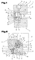
- FIG. 1 and 2 is a detail of an injection mold 1, consisting of a lower mold part 2 and a upper mold part 3, which are adjustable relative to each other, shown in the formation of a mold corner 4.
- the injection mold 1 is stretched with the lower mold part 2 and the upper mold part 3 in an injection molding machine, not shown, through which the relative adjustment for closing and opening of the injection mold 1 for an injection process and a removal operation of a molded part 5 takes place.
- the injection molding 5 is, for example, a transport box 6, in particular bottle crate 7, as described in detail below in a simplified representation of Fig. 3 can be seen.
- This consists of a box base 8 and four with the box bottom 8 an inner space 9 bounding side walls 10 and the interior 9 dividing réellegefache 11th
- the box bottom 8 forms with the side walls 10 and the réellegefache 11 a one-piece base shell which may also be double-walled by the formation of cavities, in particular to avoid accumulation of material.
- the figure shows a substantially rectangular box with box bottom 8 and four side walls 10, which are aligned at right angles to each other. Rectangular to the box bottom 8 extending box edges 13 are rounded and is applied in these areas on the base shell of a first plastic a to the box edge 13 and a portion of a side wall height 14 extending envelope layer 15 of a second plastic.
- the cladding layer 15 consists, for example, of the plastic material of the base shell 12 of different plastic material with different mechanical properties and / or a design element, e.g. differs in color from the material of the base shell 12.
- the injection mold 1 is in the Fig. 1 and 2 in the for injection molding of the base shell 12 closed position in which the upper mold part 3 and the lower mold part 2 are adjusted to each other and between a bottom mold part 16 and side wall parts 17 of the upper mold part 3 and a core mold part 18 of the mold part 2, a cavity 19 for injecting the plastic mass and thus to form the box bottom 8 with the Side walls 10 corresponding to an intended wall thickness or wall education exists.
- the mold corner 4 between the adjacent and an angle of 90 ° to each other enclosing wall moldings 12 is formed by a, arranged in a miter angle of 45 ° Eckformteil 20, with the core mold part 18 facing, formed by an internally rounded groove molding surface 21 on the core molding 18th , optionally over a height 22 of the Eckformteil 20, partially applied to the core molding 18.
- the corner molding 20 comprises with the profiled molding surface 21, the edge edge 13 corresponding to an intended dimension of the applied to the base shell 12 in the further injection molding coating layer 15th
- the corner molding 20 is fitted between opposite miter surfaces 23, 24 of the wall moldings 17, wherein the miter faces 23, 24 on side surfaces 25, 26 of the Eckformteils 20 in the closed state of the injection mold 1 tight fit.
- the corner molding 20 is adjustable between the miter surfaces 23, 24 of the wall moldings 17 in the plane of the 45 ° Miter angle in two positions.
- vertical actuator 30 is arranged in the upper mold part 3 a, acting on a, formed by a clamping surface 28 in the upper mold part 3 level 29 vertical actuator 30 is arranged.
- the actuator 30 for the Eckformteil 20 is generally formed by a arranged in a platen 32 of the upper mold part 3 adjusting means 33, eg hydraulic cylinder 34, with a perpendicular to the clamping surface 28 aligned piston rod 35 and an actuatable wedge 36.
- the adjusting wedge 36 has with respect to the linear guide assembly 37 in the direction of adjustment - according to double arrow 39 - inclined running guide assembly 40 with a T-groove guide 41, in which the Eckformteil 20 is guided with a counter-trained Systemssfortsatz on one of the mold surface 21 opposite back.
- a linear adjustment of the corner molding 20 in a direction parallel to the plane 29 - according to Doppepfeil 27 - causes.
- a driver element 42 for a positioning of the corner molding 20 with respect to the adjacent wall moldings 17, regardless of their variable position with respect to the clamping surface 28 of the platen 32, a driver element 42, in the illustrated embodiment, a cylindrical pin 43, the corner molding 20 in a slot 44 formed Guide means 45 crossing, provided.
- This is arranged in bores 46, 47 in the opposing miter surfaces 23, 24 of the wall moldings 17 and thus extends a longitudinal central axis 48 of the cylindrical pin 43 perpendicular to the adjustment direction - according to double arrow 27 - the corner molding 20th
- the cylindrical pin 43 is, for example, in one of the bores 46, 47 supported via a press fit and received in the further bore 46, 47 via a sliding seat.
- the slot 44 extends in the adjustment direction - according to double arrow 27 - of the corner molding 20, whereby its adjustment is ensured by means of the wedge 36 at the desired intervals of the molding surface 21 to the core molding 18.
- a total length 49 of the adjusting wedge 36 in the direction of its actuating direction - according to double arrow 39 - is smaller than an inner height 50 between the contact surface 48 in the lower mold part 2 and the clamping surface 28 of the upper mold part.
- the position of the corner molding 20 for molding the cladding layer 14 on the base shell 12 is shown.
- the adjusting wedge 36 is adjusted by means of the adjusting means 30 in an upper stop position in which this is adjusted against the clamping surface 28.
- the core mold member 20 is adjusted with its mold surface 21 to form a predetermined distance from the core mold part 18. In this position, the injection of the further plastic material into the released cavity takes place in the edge region of the transport box 6.
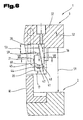
- the injection mold 1 is shown in a partially open position, wherein the removal movement of the injection molding is not yet completed, ie that for the removal of the molding a final distance 51 between the mold base 2 and the upper mold part 3 in the illustration shown is not yet reached.
- the side wall parts 17 are not shown further and known from the prior art actuators, e.g. Hydraulic cylinder, adjusted by the system at the clamping surface 28 of the clamping plate 32 by a distance 53. This adjustment takes place along inclined guide columns 54 which are arranged fixed in a bore 55 of the clamping plate 32. Bearing bushes 56 in holes 57 of the side wall parts 17 ensure precise guidance of the side wall parts 17 for an adjustment in inclined planes corresponding to an angle 58 of the inclined position of the guide columns 54 relative to the clamping surface 28.
- the angle 58 is preferably about 60 °.
- this cylindrical pin 43 in conjunction with the guide means 45 formed by the elongated hole 44 in the corner molding 20, by the relative movement relative to the wedge 36 which rests in its end position on contact with the clamping surface 28 and in conjunction with the inclined T. -Nut Adjust 41 between the wedge 36 and the Eckformteil 20 a further adjustment of the corner molding 20, according to - arrow 60 - for a further distancing of the molding surface 21 of the corner molding 20 from the core molding 18th
- the corner molding 20 has a T-shaped cross-section and is a thickness 61 in the region of the mold surface 21 is smaller than a thickness 62 in the region of the T-groove guide 41.
- a support assembly 63 for the wedge 36 with the adjustably guided on this Eckformteil 20 is achieved by the adjusting wedge 36 facing support surfaces 64, 65 on the wall moldings 17, the force acting on the Eckformteil 20 force - according to arrow 66 - when injecting the plastic material in the cavity 19, respectively gegen Eisen at an angle of 45 ° to the force direction of the force - are aligned according to arrow 66 - and thus parallel outer surfaces 67, 68 of the wall moldings 17 are aligned.
- the adjusting wedge 36 is adapted by an approximately hexagonal cross-sectional formation of the orientation of the support surfaces 64, 65 whereby cooperating with the support surfaces 64, 65 contact surfaces 69, 70 for power dissipation in the wall moldings 17 can be achieved.
- This support assembly 63 allows small dimensions of the adjusting wedge 36 and the columnar guide member 38 to which the adjusting wedge 36 in the linear guide assembly 37 is adjustably guided and which is fixed to the end face of the clamping plate 32 and protrudes freely in the direction of the lower mold part 2.
Abstract
Description
Die Erfindung betrifft ein Spritzgießwerkzeug wie es im Oberbegriff des Anspruches 1 beschrieben ist.The invention relates to an injection molding tool as described in the preamble of
Aus der
Aus der
Aufgabe der Erfindung ist es, ein Spritzgießwerkzeug mit einem einen Kernformteil aufweisenden Werkzeugunterteil und mit den Kernformteil zumindest bereichsweise in einem variierbaren Abstand zur Ausbildung einer veränderbaren Kavität umschließenden Wand- und Eckformteilen zu schaffen bei dem eine Verstellung der Formenteile für eine bereichsweise Veränderung der Kavität und eine Öffnung des Spritzgießwerkzeuges für eine Entnahme des Spritzlings mit einer geringen Anzahl von Antriebskomponenten erreicht wird.The object of the invention is to provide an injection mold with a core mold part having tool base and the core molding at least partially in a variable distance to form a variable cavity enclosing wall and Eckformteilen in which an adjustment of the mold parts for a region-wise modification of the cavity and a Opening the injection mold for removal of the molding is achieved with a small number of drive components.
Diese Aufgabe der Erfindung wird durch die im Kennzeichenteil des Anspruches 1 wiedergegebenen Merkmale erreicht. Der überraschende Vorteile ist, dass dadurch eine Antriebskoppelung zwischen den dem Kernformteil für einen Spritzvorgang umschließenden Formteilen erreicht wird die eine synchrone Bewegung der Formteile in eine vom Kernformteil entfernte Position gewährleistet und eine zusätzliche Relativverstellung der Eckformteile zu den Wandformteilen erreicht wird.This object of the invention is achieved by the reproduced in the characterizing part of
Möglich ist dabei eine Ausführung nach Anspruch 2, wodurch die Relativbewegung zwischen dem Eckformteil und dem Kernformteil in zwei zueinander rechtwinkelig verlaufenden Stellrichtungen gewährleistet ist.It is possible an embodiment according to
Vorteilhaft sind aber auch Ausbildungen nach den Ansprüchen 3 bis 6, wodurch eine exakte Positionierung des vom Stellkeil betätigten Eckformteils erreicht wird und exakte Endpositionen durch die Abstimmung eines Keilwinkels und dem Verstellweg des Stellkeils zwischen exakt definierten Endpositionen gewährleistet ist.But are also advantageous embodiments according to
Die in den Ansprüchen 7 und 8 beschriebene vorteilhafte Ausbildung gewährleistet eine Querverbindung der Wandformteile und damit exakte Höhenpositionierung der Wandformteile im Eckbereich des Werkzeuges.The advantageous embodiment described in
Die vorteilhafte Ausbildung wie im Anspruch 9 beschrieben gewährleistet eine exakte Führung der bei einem Verstellvorgang längs den geneigten Verstellebenen für eine Distanzierung der Wandformteile vom Kernformteil relativ zueinander bewegten Wandformteilen.The advantageous embodiment as described in
Durch die im Anspruch 10 beschriebene vorteilhafte Ausbildung wird eine sehr einfache Führungsanordnung für den Eckformteil am Mitnehmerelement erreicht.Due to the advantageous embodiment described in
Die im Anspruch 11 beschriebene vorteilhafte Ausbildung gewährleistet eine ausreichende Distanzierung der Eckformteile für den Entformvorgang.The advantageous embodiment described in
Vorteilhaft sind weiters die in den Ansprüchen 12 bis 14 beschriebenen Ausbildungen, weil dadurch einerseits eine exakte Führung des Eckformteils zwischen den Wandformteilen an den Gehrungsflächen erreicht wird und durch die beschriebene Querschnittsausbildung des Eckformteils einerseits eine sehr dichte Anlage und andererseits ein exakter Endanschlag für die Verstellung des Eckformteils in Richtung des Kernformteils und damit eine exakte Spaltausbildung für die Kavität erreicht wird.Also advantageous are the embodiments described in
Durch die in den Ansprüchen 15 bis 17 beschriebenen vorteilhaften Ausbildungen erfolgt ein synchrones Verstellen der Wandformteile und der mit diesen antriebsverbundenen Eckformteilen mit der Öffnungsverstellung des Spritzgießwerkzeuges, wodurch eine Relativbewegung der Wandformteile und Eckformteile gegenüber dem Spritzling vermieden wird.Due to the advantageous embodiments described in
Die Ansprüche 18 bis 21 beschreiben weitere vorteilhafte Ausbildungen, wodurch eine hohe Dauerstandsfestigkeit der Führungen und Betätigungseinrichtungen erreicht wird.The
Schließlich sind auch Ausbildungen gemäß den Ansprüchen 22 bis 25 vorteilhaft, da damit der Stellkeil gegen die Wirkung der durch den Druck in der Kavität beim Einspritzen der Kunststoffmasse auf den Eckformteil ausgeübten Kraft durch die beim Einspritzvorgang verriegelten Wandformteile abgestützt wird und damit eine Krafteinwirkung auf das Führungselement, dessen Befestigung und die Linearführungsanordnung wirkungsvoll vermieden wird. Dies gewährleistet geringe Abmessungen der Bauteile in den Eckbereichen und somit insgesamt kleinere sowie Gewicht und Kosten sparende Spritzgießwerkzeuge.Finally, embodiments according to
Zum besseren Verständnis der Erfindung wird diese anhand der in den Figuren gezeigten Ausführungsbeispiele näher erläutert.For a better understanding of the invention, this will be explained in more detail with reference to the embodiments shown in FIGS.
Es zeigen:
- Fig. 1
- den Eckbereich des erfindungsgemäßen Spritzgießwerkzeuges in Stellung des Eckformteil zum Spritzen der Grundschale, geschnitten gemäß den Linien I-I in
Fig. 2 ; - Fig. 2
- den Eckbereich des Spritzgießwerkzeuges, geschnitten gemäß den Linien II-II in
Fig. 1 ; - Fig. 3
- einen Eckbereich eines mit dem erfindungsgemäßen Spritzgießwerkzeug produzierten Transportkasten in perspektivischer Ansicht;
- Fig. 4
- der Eckbereich des erfindungsgemäßen Spritzgießwerkzeuges in Stellung des Eckformteils zum Aufspritzen der Hüllschicht auf die Grundschale, geschnitten gemäß den Linien IV-IV in
Fig. 5 ; - Fig. 5
- der Eckbereich geschnitten gemäß den Linien V-V in
Fig. 4 ; - Fig. 6
- das erfindungsgemäße Spritzgießwerkzeug in geöffneter Position mit zurückge-zogener Stellung des Eckformteils, geschnitten gemäß den Linien VI-VI in
Fig. 7 ; - Fig. 7
- den Eckbereich des geöffneten Spritzgießwerkzeuges, geschnitten gemäß den Linien VII-VII in
Fig. 6 ; - Fig. 8
- einen Teilbereich des Formoberteils mit dem Wandformteil des erfindungsgemäßen Spritzgießwerkzeuges in geöffneter Position der Wandformteile, geschnitten gemäß den Linien VIII-VIII in
Fig. 2 .
- Fig. 1
- the corner region of the injection mold according to the invention in position of the corner molding for spraying the base shell, cut according to the lines II in
Fig. 2 ; - Fig. 2
- the corner region of the injection mold, cut according to the lines II-II in
Fig. 1 ; - Fig. 3
- a corner region of a transport box produced by the injection molding tool according to the invention in a perspective view;
- Fig. 4
- the corner region of the injection molding tool according to the invention in position of the corner molding for spraying the cladding layer on the base shell, cut in accordance with the lines IV-IV in
Fig. 5 ; - Fig. 5
- the corner area is cut according to the lines VV in
Fig. 4 ; - Fig. 6
- the injection mold according to the invention in the open position with retracted position of the corner molding, cut according to the lines VI-VI in
Fig. 7 ; - Fig. 7
- the corner region of the opened injection mold, cut according to the lines VII-VII in
Fig. 6 ; - Fig. 8
- a portion of the upper mold with the wall molding of the injection mold according to the invention in the open position of the wall moldings, cut according to the lines VIII-VIII in
Fig. 2 ,
Einführend sei festgehalten, dass in den unterschiedlich beschriebenen Ausführungsformen gleiche Teile mit gleichen Bezugszeichen bzw. gleichen Bauteilbezeichnungen versehen werden, wobei die in der gesamten Beschreibung enthaltenen Offenbarungen sinngemäß auf gleiche Teile mit gleichen Bezugszeichen bzw. gleichen Bauteilbezeichnungen übertragen werden können. Auch sind die in der Beschreibung gewählten Lageangaben, wie z.B. oben, unten, seitlich usw. auf die unmittelbar beschriebene sowie dargestellte Figur bezogen und sind bei einer Lageänderung sinngemäß auf die neue Lage zu übertragen. Weiters können auch Einzelmerkmale oder Merkmalskombinationen aus den gezeigten und beschriebenen unterschiedlichen Ausführungsbeispielen für sich eigenständige, erfinderische oder erfindungsgemäße Lösungen darstellen.By way of introduction, it should be noted that in the differently described embodiments, the same parts are provided with the same reference numerals or the same component names, wherein the disclosures contained in the entire description can be mutatis mutandis to the same parts with the same reference numerals or component names. Also, the location information chosen in the description, such as top, bottom, side, etc. related to the immediately described and illustrated figure and are to be transferred to the new situation mutatis mutandis when a change in position. Furthermore, individual features or combinations of features from the different exemplary embodiments shown and described can also represent independent, inventive or inventive solutions.
Sämtliche Angaben zu Wertebereichen in gegenständlicher Beschreibung sind so zu verstehen, dass diese beliebige und alle Teilbereiche daraus mit umfassen, z.B. ist die Angabe 1 bis 10 so zu verstehen, dass sämtliche Teilbereiche, ausgehend von der unteren Grenze 1 und der oberen Grenze 10 mitumfasst sind, d.h. sämtliche Teilbereich beginnen mit einer unteren Grenze von 1 oder größer und enden bei einer oberen Grenze von 10 oder weniger, z.B. 1 bis 1,7, oder 3,2 bis 8,1 oder 5,5 bis 10.All statements on ranges of values in objective description are to be understood as including any and all sub-ranges thereof, eg the
In den
Das Spritzgießwerkzeug 1 ist mit dem Formunterteil 2 und dem Formoberteil 3 in einer nicht weiter dargestellten Spritzgießmaschine gespannt, durch welche die Relativverstellung zum Schließen und Öffnen des Spritzgießwerkzeuges 1 für einen Spritzvorgang und einen Entnahmevorgang eines Spritzlings 5 erfolgt.The
Der Spritzling 5 ist bspw. ein Transportkasten 6, insbesondere Flaschenkasten 7, wie er im Detail im Weiteren in vereinfachter Darstellung der
Der Kastenboden 8 bildet mit den Seitenwänden 10 und dem Innengefache 11 eine einstückige Grundschale die teilweise durch Ausbildung von Hohlräumen auch doppelwandig sein kann, insbesondere zur Vermeidung von Materialanhäufungen.The box bottom 8 forms with the
Die Abbildung zeigt einen im Wesentlichen recheckigen Kasten mit Kastenboden 8 und vier Seitenwänden 10, die zueinander rechtwinkelig ausgerichtet sind. Rechtwinkelig zum Kastenboden 8 verlaufende Kastenkanten 13 sind gerundet ausgebildet und ist in diesen Bereichen auf der Grundschale aus einem ersten Kunststoff eine sich um die Kastenkante 13 und einem Teilbereich einer Seitenwandhöhe 14 erstreckende Hüllschicht 15 aus einem zweiten Kunststoff aufgebracht.The figure shows a substantially rectangular box with box bottom 8 and four
Diese wird durch einen zweiten Spritzvorgang im Spritzgießwerkzeug 1 durch Veränderung einer Formkavität im Bereich der Formecke 4 erreicht wobei die Hüllschicht 15 auf die noch nicht gänzlich erkaltete Grundschale 12 aufgespritzt wird. Die Hüllschicht 15 besteht bspw. aus zum Kunststoffmaterial der Grundschale 12 unterschiedlichen Kunststoffmaterial mit anderen mechanischen Eigenschaften und/oder ein Designelement ist, z.B. sich farblich vom Material der Grundschale 12 unterscheidet.This is achieved by a second injection process in the
Das Spritzgießwerkzeug 1 ist in den
Die Formecke 4 zwischen den benachbarten und einen Winkel von 90° zueinander einschließenden Wandformteilen 12 wird durch einen, in einem Gehrungswinkel von 45° angeordneten Eckformteil 20 gebildet, der mit einer dem Kernformteil 18 zugewandten, durch eine innen gerundete Nut ausgebildeten Formfläche 21 am Kernformteil 18, über eine Höhe 22 des Eckformteil 20, gegebenenfalls bereichsweise am Kernformteil 18 anliegt.The mold corner 4 between the adjacent and an angle of 90 ° to each other enclosing
Dadurch verbleiben an der zu bildenden Kastenkante 13 der Grundschale 12 Wandunterbrechungen beim ersten Spritzvorgang und Einspritzen der Kunststoffinasse für die Grundschale 12, wodurch noch zusätzlich eine Verankerung mit der Hüllschicht 15 erreicht werden kann.This leaves at the
Der Eckformteil 20 umfasst mit der profilierten Formfläche 21 die Kantenkante 13 entsprechend einer vorgesehenen Abmessung der auf die Grundschale 12 im weiteren Spritzvorgang aufzubringenden Hüllschicht 15.The
Der Eckformteil 20 ist zwischen gegenüberliegende Gehrungsflächen 23, 24 der Wandformteile 17 eingepasst, wobei die Gehrungsflächen 23, 24 an Seitenflächen 25, 26 des Eckformteils 20 im geschlossenen Zustand des Spritzgießwerkzeuges 1 dicht anliegen.The
Der Eckformteil 20 ist zwischen den Gehrungsflächen 23, 24 der Wandformteile 17 in der Ebene des 45°-igen Gehrungswinkel in zwei Positionen verstellbar. Dazu ist im Formoberteil 3 ein, zu einer, durch eine Spannfläche 28 im Werkzeugoberteil 3 gebildeten Ebene 29 senkrechter Richtung wirkender Stellantrieb 30, angeordnet.The
Der Stellantrieb 30 für den Eckformteil 20 wird insgesamt durch ein in einer Aufspannplatte 32 des Formoberteils 3 angeordnetes Stellmittel 33, z.B. Hydraulikzylinder 34, mit einer senkrecht zur Spannfläche 28 ausgerichteten Kolbenstange 35 und einem damit betätigbaren Stellkeil 36 gebildet.The
Dieser ist in einer Linearführungsanordnung 37, eines an der Aufspannplatte 32 befestigten und in Richtung des Formunterteils 2 erstreckenden Führungselement 38, in zur Ebene 29 senkrechten Richtung - gemäß Doppelpfeil 39 - verstellbar.This is in a
Der Stellkeil 36 weist gegenüber der Linearführungsanordnung 37 eine in Stellrichtung - gemäß Doppelpfeil 39 - geneigt verlaufende Führungsanordnung 40 mit einer T- Nutführung 41 auf, in welcher der Eckformteil 20 mit einem gegengleich ausgebildeten Führungsfortsatz an einer der Formfläche 21 entgegen gesetzten Rückseite geführt ist. Damit wird bei einer Verstellung des Stellkeils 36, in einer zu der Ebene 29 senkrechten Richtung, eine lineare Verstellung des Eckformteils 20, in einer zur Ebene 29 parallelen Richtung - gemäß Doppepfeil 27 - bewirkt.The adjusting
Dies ermöglicht den Eckformteil 20 in Abhängigkeit einer Relativstellung zwischen dem Eckformteil 20 und dem Stellkeil 36 die Formfläche 21 in einem variierbaren stufenlosen Abstand in Bezug auf den Kernförmteil 18 zu positionieren. Damit wird eine veränderbare Kavität zwischen dem Kernformteil 18 und der diesem zugewandten Formfläche 21 des Eckformteils 20 erreicht, wie auch eine distanzierte Position wie sie für das Öffnen des Spritzgießwerkzeuges 1 und für das Entformen des Spritzlings 5 erforderlich ist.This allows the
Für eine Positionierung des Eckformteils 20 in Bezug auf die benachbarten Wandformteile 17, unabhängig von deren variierbaren Position in Bezug auf die Spannfläche 28 der Aufspannplatte 32, ist ein Mitnehmerelement 42, im gezeigten Ausführungsbeispiel ein Zylinderstift 43, den Eckformteil 20 in einem als Langloch 44 ausgebildeten Führungsmittel 45 querend, vorgesehen. Dieser ist in Bohrungen 46, 47 in den einander gegenüberliegenden Gehrungsflächen 23, 24 der Wandformteile 17 angeordnet und verläuft somit eine Längsmittelachse 48 des Zylinderstifts 43 senkrecht zur Verstellrichtung - gemäß Doppelpfeil 27 - des Eckformteils 20.For a positioning of the
Der Zylinderstift 43 ist bspw. in einer der Bohrungen 46, 47 über einen Presssitz gehaltert und in der weiteren Bohrung 46, 47 über einen Schiebesitz aufgenommen. Das Langloch 44 erstreckt sich in Verstellrichtung - gemäß Doppelpfeil 27 - des Eckformteils 20, wodurch dessen Verstellung mittels des Stellkeils 36 in den gewünschten Abständen der Formfläche 21 zum Kernformteil 18 gewährleistet ist.The
In der in der
Eine Gesamtlänge 49 des Stellkeils 36 in Richtung seiner Stellrichtung - gemäß Doppelpfeil 39 - ist kleiner als eine Innenhöhe 50 zwischen der Anlagefläche 48 im Formunterteil 2 und der Spannfläche 28 des Formoberteils 3.A
In der
Die Positionen des Kernformteils 20 für eine erste Stellung bei der die Grundschale 12 gespritzt wird und einer zweiten Stellung bei der die Hüllschicht 15 gespritzt wird, wird durch eine exakte Abstimmung der Gesamtlänge 49 des Stellkeils 36 und der Innenhöhe 50 zwischen der Anlagefläche 48 im Formunterteil 2 und der Spannfläche 28 im Formoberteil sowie der maßlichen Abstimmung des Kernformteils 20 und des Stellkeils 36 und der Distanz zwischen dem Kernformteil bzw. der Formkante und dem Führungselement 38 für den Stellkeil 36 erreicht.The positions of the
In den
Synchron mit einer von der nicht weiter dargestellten Spritzgießmaschine bewirkten Öffnungsbewegung - gemäß Pfeil 52 - z.B. des Formoberteils 3 werden die Seitenwandteile 17 über nicht weiter gezeigte und aus dem Stand der Technik bekannte Stellantriebe, z.B. Hydraulikzylinder, von der Anlage an der Spannfläche 28 der Aufspannplatte 32 um einen Abstand 53 verstellt. Dieser Verstellvorgang erfolgt längs schräg gestellter Führungssäulen 54 die in einer Bohrung 55 der Aufspannplatte 32 festsitzend angeordnet sind. Lagerbüchsen 56 in Bohrungen 57 der Seitenwandteile 17 gewährleisten eine exakte Führung der Seitenwandteile 17 für eine Verstellung in geneigten Ebenen entsprechend einem Winkel 58 der Schrägstellung der Führungssäulen 54 gegenüber der Spannfläche 28. Der Winkel 58 beträgt bevorzugt etwa 60°.Synchronous with an opening movement effected by the injection molding machine (not shown) - as indicated by arrow 52 - e.g. of the
Gleichzeitig mit der Verstellung um den Abstand 53 zwischen der Spannfläche 28 und Stirnflächen 59 der Wandformteile 17 wird infolge der Verstellung in den geneigten Ebenen eine Distanzierung zwischen den Gehrungsflächen 23, 24 der Seitenwandteile 17 erreicht, d. h. die Seitenwandteile 17 werden dadurch zur Öffnung der Kavität vom Kernformteil 18 distanziert, wobei die Wandformteile 17 zueinander in der Formecke 4 noch zusätzlich durch den Zylinderstift 43 geführt sind.Simultaneously with the adjustment by the
Wie bereits vorhergehend beschrieben, bewirkt dieser Zylinderstift 43 in Verbindung mit der durch das Langloch 44 im Eckformteil 20 gebildeten Führungsmittel 45, durch die Relativbewegung gegenüber dem Stellkeil 36, der in seiner Endstellung auf Anlage an der Spannfläche 28 anliegt und in Verbindung mit der geneigten T-Nutführung 41 zwischen dem Stellkeil 36 und dem Eckformteil 20 eine weitere Verstellung des Eckformteils 20, gemäß - Pfeil 60 - für eine weitere Distanzierung der Formfläche 21 des Eckformteils 20 vom Kernformteil 18.As already described above, this
Der
Wie den
Diese Stützanordnung 63 ermöglicht geringe Abmessungen des Stellkeils 36 und des säulenartigen Führungselementes 38 an dem der Stellkeil 36 in der Linearführungsanordnung 37 verstellbar geführt ist und das stirnseitig an der Aufspannplatte 32 befestigt ist und in Richtung des Formunterteils 2 frei ausragt.This
Die Ausführungsbeispiele zeigen mögliche Ausführungsvarianten des Spritzgießwerkzeuges 1, wobei an dieser Stelle bemerkt sei, dass die Erfindung nicht auf die speziell dargestellten Ausführungsvarianten derselben eingeschränkt ist, sondern vielmehr auch diverse Kombinationen der einzelnen Ausführungsvarianten untereinander möglich sind und diese Variationsmöglichkeit aufgrund der Lehre zum technischen Handeln durch gegenständliche Erfindung im Können des auf diesem technischen Gebiet tätigen Fachmannes liegt. Es sind also auch sämtliche denkbaren Ausführungsvarianten, die durch Kombinationen einzelner Details der dargestellten und beschriebenen Ausführungsvariante möglich sind, vom Schutzumfang mit umfasst.The embodiments show possible embodiments of the
Der Ordnung halber sei abschließend darauf hingewiesen, dass zum besseren Verständnis des Aufbaus des Spritzgießwerkzeuges dieses bzw. dessen Bestandteile teilweise unmaßstäblich und/oder vergrößert und/oder verkleinert dargestellt wurden.For the sake of order, it should finally be pointed out that, for a better understanding of the construction of the injection molding tool, this or its components have been shown partially unevenly and / or enlarged and / or reduced in size.
Die den eigenständigen erfinderischen Lösungen zugrunde liegende Aufgabe kann der Beschreibung entnommen werden.The problem underlying the independent inventive solutions can be taken from the description.
Vor allem können die einzelnen in den
- 11
- Spritzgießwerkzeuginjection mold
- 22
- FormunterteilMold part
- 33
- FormoberteilMold top
- 44
- Formeckemolded corner
- 55
- Spritzlingsprue
- 66
- Transportkastenshipping boxes
- 77
- Flaschenkastenbottle case
- 88th
- Kastenbodenbox bottom
- 99
- Innenrauminner space
- 1010
- Seitewandside wall
- 1111
- Innengefacheinner compartments
- 1212
- GrundschaleSake cup
- 1313
- Kastenkantebox edge
- 1414
- SeitenwandhöheSidewall height
- 1515
- Hüllschichtshell layer
- 1616
- BodenformteilFloor molding
- 1717
- WandformteilWall molding
- 1818
- KernformteilCore molding
- 1919
- Kavitätcavity
- 2020
- Eckformteilcorner molding
- 2121
- Formflächeform surface
- 2222
- Höheheight
- 2323
- Gehrungsflächemiter
- 2424
- Gehrungsflächemiter
- 2525
- Seitenflächeside surface
- 2626
- Seitenflächeside surface
- 2727
- Doppelpfeildouble arrow
- 2828
- Spannflächeclamping surface
- 2929
- Ebenelevel
- 3030
- Stellantriebactuator
- 3131
- 3232
- Aufspannplatteplaten
- 3333
- Stellmittelactuating means
- 3434
- Druckzylinderpressure cylinder
- 3535
- Kolbenstangepiston rod
- 3636
- Stellkeilgib
- 3737
- LinearführungsanordnungLinear guide arrangement
- 3838
- Führungselementguide element
- 3939
- Doppelpfeildouble arrow
- 4040
- Führungsanordnungguide assembly
- 4141
- T-NutführungT-groove guide
- 4242
- Mitnehmerelementdogging
- 4343
- Zylinderstiftstraight pin
- 4444
- LanglochLong hole
- 4545
- Führungsmittelguide means
- 4646
- Bohrungdrilling
- 4747
- Bohrungdrilling
- 4848
- Anlageflächecontact surface
- 4949
- Gesamtlängeoverall length
- 5050
- Innenhöheinterior height
- 5151
- Distanzdistance
- 5252
- Pfeilarrow
- 5353
- Abstanddistance
- 5454
- Führungssäuleguide column
- 5555
- Bohrungdrilling
- 5656
- Lagerbüchsebearing bush
- 5757
- Bohrungdrilling
- 5858
- Winkelangle
- 5959
- Stirnflächeface
- 6060
- Pfeilarrow
- 6161
- Dickethickness
- 6262
- Dickethickness
- 6363
- Stützanordnungsupport assembly
- 6464
- Stützflächesupport surface
- 6565
- Stützflächesupport surface
- 6666
- Pfeilarrow
- 6767
- Außenflächeouter surface
- 6868
- Außenflächeouter surface
- 6969
- Anlageflächecontact surface
- 7070
- Anlageflächecontact surface
Claims (25)
Applications Claiming Priority (1)
| Application Number | Priority Date | Filing Date | Title |
|---|---|---|---|
| AT0033908A AT506606B1 (en) | 2008-03-03 | 2008-03-03 | INJECTION MOLD |
Publications (3)
| Publication Number | Publication Date |
|---|---|
| EP2098352A2 true EP2098352A2 (en) | 2009-09-09 |
| EP2098352A3 EP2098352A3 (en) | 2009-09-23 |
| EP2098352B1 EP2098352B1 (en) | 2011-01-26 |
Family
ID=40756732
Family Applications (1)
| Application Number | Title | Priority Date | Filing Date |
|---|---|---|---|
| EP09003008A Active EP2098352B1 (en) | 2008-03-03 | 2009-03-03 | Injection moulding tool |
Country Status (3)
| Country | Link |
|---|---|
| EP (1) | EP2098352B1 (en) |
| AT (2) | AT506606B1 (en) |
| DE (1) | DE502009000335D1 (en) |
Cited By (2)
| Publication number | Priority date | Publication date | Assignee | Title |
|---|---|---|---|---|
| EP2599608A1 (en) * | 2011-12-02 | 2013-06-05 | Haidlmair Holding GmbH | Injection moulding tool, in particular a jaw tool |
| EP2808151A1 (en) * | 2013-05-27 | 2014-12-03 | Schoeller Allibert GmbH | Demolding mechanism of an injection molding tool |
Families Citing this family (2)
| Publication number | Priority date | Publication date | Assignee | Title |
|---|---|---|---|---|
| DE202009007083U1 (en) | 2009-05-16 | 2009-08-06 | Delbrouck Gmbh | Cuboid bottle crate |
| DE102018106891B4 (en) * | 2018-03-22 | 2020-06-18 | Meusburger GmbH & Co. KG | Slide unit for injection and die casting molds |
Citations (2)
| Publication number | Priority date | Publication date | Assignee | Title |
|---|---|---|---|---|
| DE102005059976A1 (en) | 2005-12-13 | 2007-06-14 | Linpac Materials Handling (Germany) Gmbh | Method for manufacturing injection moulded plastics transport crates uses one mould having separate movable moulded corner members between wall members so that first one plastics is injected and solidifies before injecting second plastics |
| EP1820738A1 (en) | 2006-02-20 | 2007-08-22 | Haidlmair GmbH | Transport case, in particular bottle case |
Family Cites Families (2)
| Publication number | Priority date | Publication date | Assignee | Title |
|---|---|---|---|---|
| DE2849145C3 (en) * | 1978-11-13 | 1981-12-24 | Maschinenfabrik Köppern GmbH & Co KG, 4320 Hattingen | Injection mold for transport boxes, in which the Formbachken can be moved on inclined guide pillars |
| DE10353751A1 (en) * | 2003-11-17 | 2005-06-30 | Theysohn Formenbau Gmbh | Injection-molded crate for holding bottles has a surface layer of a different material molded on inside or outside of side wall region |
-
2008
- 2008-03-03 AT AT0033908A patent/AT506606B1/en not_active IP Right Cessation
-
2009
- 2009-03-03 AT AT09003008T patent/ATE496750T1/en active
- 2009-03-03 DE DE502009000335T patent/DE502009000335D1/en active Active
- 2009-03-03 EP EP09003008A patent/EP2098352B1/en active Active
Patent Citations (2)
| Publication number | Priority date | Publication date | Assignee | Title |
|---|---|---|---|---|
| DE102005059976A1 (en) | 2005-12-13 | 2007-06-14 | Linpac Materials Handling (Germany) Gmbh | Method for manufacturing injection moulded plastics transport crates uses one mould having separate movable moulded corner members between wall members so that first one plastics is injected and solidifies before injecting second plastics |
| EP1820738A1 (en) | 2006-02-20 | 2007-08-22 | Haidlmair GmbH | Transport case, in particular bottle case |
Cited By (3)
| Publication number | Priority date | Publication date | Assignee | Title |
|---|---|---|---|---|
| EP2599608A1 (en) * | 2011-12-02 | 2013-06-05 | Haidlmair Holding GmbH | Injection moulding tool, in particular a jaw tool |
| EP2808151A1 (en) * | 2013-05-27 | 2014-12-03 | Schoeller Allibert GmbH | Demolding mechanism of an injection molding tool |
| WO2014191360A1 (en) * | 2013-05-27 | 2014-12-04 | Schoeller Allibert Gmbh | Demoulding mechanism for an injection mould |
Also Published As
| Publication number | Publication date |
|---|---|
| DE502009000335D1 (en) | 2011-03-10 |
| EP2098352B1 (en) | 2011-01-26 |
| ATE496750T1 (en) | 2011-02-15 |
| AT506606A1 (en) | 2009-10-15 |
| EP2098352A3 (en) | 2009-09-23 |
| AT506606B1 (en) | 2009-12-15 |
Similar Documents
| Publication | Publication Date | Title |
|---|---|---|
| EP0722820B1 (en) | Tie bar-less mould clamping device | |
| EP1916361A1 (en) | Handle for mounting in an opening | |
| EP1764173B1 (en) | Powder moulding press | |
| EP2098352B1 (en) | Injection moulding tool | |
| DE102005063327B4 (en) | Device for separating a plastic clay cord, with an effective notching device | |
| DE102005021038B4 (en) | Device for separating a plastic clay cord, with an effective notching device | |
| WO1997031770A1 (en) | Mould closure device for a moulding tool in an injection moulding machine | |
| DE3038160A1 (en) | INJECTION MOLDING DEVICE | |
| EP1787784A1 (en) | Mould for manufacturing parts by injection moulding, pressure die casting or a deposition method | |
| EP2134528B1 (en) | Moulding tool with a modular construction comprising a frame | |
| DE102004009406B4 (en) | Plastic crate molding tool has two types of tool plates, at least one of which has cavity sections facing two adjacent outer faces of the core | |
| EP0061072A2 (en) | Injection mould | |
| DE102009032620B4 (en) | Tool for the production of sand cores and machine for the production of sand cores | |
| DE102014212300B4 (en) | Method for injection molding of multi-dimensional objects and drive module for an injection molding tool | |
| AT511230A1 (en) | FORM CORE FOR MOLDING TOOL | |
| EP0738661A1 (en) | Pallet made of plastic material, process and device for its manufacturing | |
| DE2437105A1 (en) | Movable tool holder for corner jointing machine - adaptable to any profile shape and thickness with little manipulation | |
| EP0189906B1 (en) | Mould for injection-moulding stackable containers | |
| DE3708885A1 (en) | Process for producing a door | |
| AT514238B1 (en) | Vertical clamping unit for an injection molding machine | |
| DE2136644A1 (en) | Plastics pallets injection moulding - with withdrawable cores to form holes for lifting forks | |
| DE102005049654B4 (en) | Stackable valve-cylinder unit with integrally manufactured pressure medium distributor and valve-cylinder-unit arrangement | |
| DE3111254C2 (en) | Injection mold for box-shaped injection molded parts, with mold jaws guided on inclined guide columns | |
| DE10253466B3 (en) | Press, for shaping a thermoplastic motor compartment housing, has upper and lower molds which form the edge of an opening in the workpiece and the hinged flap at the opening | |
| DE4412883A1 (en) | Hollow blow moulded thermoplastic component mfg. plant for less wear |
Legal Events
| Date | Code | Title | Description |
|---|---|---|---|
| PUAI | Public reference made under article 153(3) epc to a published international application that has entered the european phase |
Free format text: ORIGINAL CODE: 0009012 |
|
| PUAL | Search report despatched |
Free format text: ORIGINAL CODE: 0009013 |
|
| AK | Designated contracting states |
Kind code of ref document: A2 Designated state(s): AT BE BG CH CY CZ DE DK EE ES FI FR GB GR HR HU IE IS IT LI LT LU LV MC MK MT NL NO PL PT RO SE SI SK TR |
|
| AX | Request for extension of the european patent |
Extension state: AL BA RS |
|
| AK | Designated contracting states |
Kind code of ref document: A3 Designated state(s): AT BE BG CH CY CZ DE DK EE ES FI FR GB GR HR HU IE IS IT LI LT LU LV MC MK MT NL NO PL PT RO SE SI SK TR |
|
| AX | Request for extension of the european patent |
Extension state: AL BA RS |
|
| AKX | Designation fees paid | ||
| 17P | Request for examination filed |
Effective date: 20100514 |
|
| RAX | Requested extension states of the european patent have changed |
Extension state: RS Payment date: 20100514 Extension state: BA Payment date: 20100514 Extension state: AL Payment date: 20100514 |
|
| RBV | Designated contracting states (corrected) |
Designated state(s): AT BE BG CH CY CZ DE DK EE ES FI FR GB GR HR HU IE IS IT LI LT LU LV MC MK MT NL NO PL PT RO SE SI SK TR |
|
| RAX | Requested extension states of the european patent have changed |
Extension state: RS Payment date: 20100514 Extension state: BA Payment date: 20100514 Extension state: AL Payment date: 20100514 |
|
| REG | Reference to a national code |
Ref country code: DE Ref legal event code: 8566 |
|
| GRAP | Despatch of communication of intention to grant a patent |
Free format text: ORIGINAL CODE: EPIDOSNIGR1 |
|
| GRAS | Grant fee paid |
Free format text: ORIGINAL CODE: EPIDOSNIGR3 |
|
| GRAA | (expected) grant |
Free format text: ORIGINAL CODE: 0009210 |
|
| AK | Designated contracting states |
Kind code of ref document: B1 Designated state(s): AT BE BG CH CY CZ DE DK EE ES FI FR GB GR HR HU IE IS IT LI LT LU LV MC MK MT NL NO PL PT RO SE SI SK TR |
|
| AX | Request for extension of the european patent |
Extension state: AL BA RS |
|
| REG | Reference to a national code |
Ref country code: GB Ref legal event code: FG4D Free format text: NOT ENGLISH |
|
| REG | Reference to a national code |
Ref country code: CH Ref legal event code: EP |
|
| REG | Reference to a national code |
Ref country code: IE Ref legal event code: FG4D Free format text: LANGUAGE OF EP DOCUMENT: GERMAN |
|
| REF | Corresponds to: |
Ref document number: 502009000335 Country of ref document: DE Date of ref document: 20110310 Kind code of ref document: P |
|
| REG | Reference to a national code |
Ref country code: DE Ref legal event code: R096 Ref document number: 502009000335 Country of ref document: DE Effective date: 20110310 |
|
| REG | Reference to a national code |
Ref country code: NL Ref legal event code: T3 |
|
| LTIE | Lt: invalidation of european patent or patent extension |
Effective date: 20110126 |
|
| PG25 | Lapsed in a contracting state [announced via postgrant information from national office to epo] |
Ref country code: LT Free format text: LAPSE BECAUSE OF FAILURE TO SUBMIT A TRANSLATION OF THE DESCRIPTION OR TO PAY THE FEE WITHIN THE PRESCRIBED TIME-LIMIT Effective date: 20110126 Ref country code: LV Free format text: LAPSE BECAUSE OF FAILURE TO SUBMIT A TRANSLATION OF THE DESCRIPTION OR TO PAY THE FEE WITHIN THE PRESCRIBED TIME-LIMIT Effective date: 20110126 Ref country code: HR Free format text: LAPSE BECAUSE OF FAILURE TO SUBMIT A TRANSLATION OF THE DESCRIPTION OR TO PAY THE FEE WITHIN THE PRESCRIBED TIME-LIMIT Effective date: 20110126 Ref country code: ES Free format text: LAPSE BECAUSE OF FAILURE TO SUBMIT A TRANSLATION OF THE DESCRIPTION OR TO PAY THE FEE WITHIN THE PRESCRIBED TIME-LIMIT Effective date: 20110507 Ref country code: SE Free format text: LAPSE BECAUSE OF FAILURE TO SUBMIT A TRANSLATION OF THE DESCRIPTION OR TO PAY THE FEE WITHIN THE PRESCRIBED TIME-LIMIT Effective date: 20110126 Ref country code: GR Free format text: LAPSE BECAUSE OF FAILURE TO SUBMIT A TRANSLATION OF THE DESCRIPTION OR TO PAY THE FEE WITHIN THE PRESCRIBED TIME-LIMIT Effective date: 20110427 Ref country code: PT Free format text: LAPSE BECAUSE OF FAILURE TO SUBMIT A TRANSLATION OF THE DESCRIPTION OR TO PAY THE FEE WITHIN THE PRESCRIBED TIME-LIMIT Effective date: 20110526 Ref country code: NO Free format text: LAPSE BECAUSE OF FAILURE TO SUBMIT A TRANSLATION OF THE DESCRIPTION OR TO PAY THE FEE WITHIN THE PRESCRIBED TIME-LIMIT Effective date: 20110426 |
|
| REG | Reference to a national code |
Ref country code: IE Ref legal event code: FD4D |
|
| PG25 | Lapsed in a contracting state [announced via postgrant information from national office to epo] |
Ref country code: CY Free format text: LAPSE BECAUSE OF FAILURE TO SUBMIT A TRANSLATION OF THE DESCRIPTION OR TO PAY THE FEE WITHIN THE PRESCRIBED TIME-LIMIT Effective date: 20110126 Ref country code: FI Free format text: LAPSE BECAUSE OF FAILURE TO SUBMIT A TRANSLATION OF THE DESCRIPTION OR TO PAY THE FEE WITHIN THE PRESCRIBED TIME-LIMIT Effective date: 20110126 Ref country code: PL Free format text: LAPSE BECAUSE OF FAILURE TO SUBMIT A TRANSLATION OF THE DESCRIPTION OR TO PAY THE FEE WITHIN THE PRESCRIBED TIME-LIMIT Effective date: 20110126 Ref country code: SI Free format text: LAPSE BECAUSE OF FAILURE TO SUBMIT A TRANSLATION OF THE DESCRIPTION OR TO PAY THE FEE WITHIN THE PRESCRIBED TIME-LIMIT Effective date: 20110126 |
|
| PG25 | Lapsed in a contracting state [announced via postgrant information from national office to epo] |
Ref country code: EE Free format text: LAPSE BECAUSE OF FAILURE TO SUBMIT A TRANSLATION OF THE DESCRIPTION OR TO PAY THE FEE WITHIN THE PRESCRIBED TIME-LIMIT Effective date: 20110126 Ref country code: DK Free format text: LAPSE BECAUSE OF FAILURE TO SUBMIT A TRANSLATION OF THE DESCRIPTION OR TO PAY THE FEE WITHIN THE PRESCRIBED TIME-LIMIT Effective date: 20110126 Ref country code: MC Free format text: LAPSE BECAUSE OF NON-PAYMENT OF DUE FEES Effective date: 20110331 Ref country code: IE Free format text: LAPSE BECAUSE OF FAILURE TO SUBMIT A TRANSLATION OF THE DESCRIPTION OR TO PAY THE FEE WITHIN THE PRESCRIBED TIME-LIMIT Effective date: 20110126 |
|
| PG25 | Lapsed in a contracting state [announced via postgrant information from national office to epo] |
Ref country code: RO Free format text: LAPSE BECAUSE OF FAILURE TO SUBMIT A TRANSLATION OF THE DESCRIPTION OR TO PAY THE FEE WITHIN THE PRESCRIBED TIME-LIMIT Effective date: 20110126 Ref country code: SK Free format text: LAPSE BECAUSE OF FAILURE TO SUBMIT A TRANSLATION OF THE DESCRIPTION OR TO PAY THE FEE WITHIN THE PRESCRIBED TIME-LIMIT Effective date: 20110126 Ref country code: CZ Free format text: LAPSE BECAUSE OF FAILURE TO SUBMIT A TRANSLATION OF THE DESCRIPTION OR TO PAY THE FEE WITHIN THE PRESCRIBED TIME-LIMIT Effective date: 20110126 |
|
| PLBE | No opposition filed within time limit |
Free format text: ORIGINAL CODE: 0009261 |
|
| STAA | Information on the status of an ep patent application or granted ep patent |
Free format text: STATUS: NO OPPOSITION FILED WITHIN TIME LIMIT |
|
| PG25 | Lapsed in a contracting state [announced via postgrant information from national office to epo] |
Ref country code: MT Free format text: LAPSE BECAUSE OF FAILURE TO SUBMIT A TRANSLATION OF THE DESCRIPTION OR TO PAY THE FEE WITHIN THE PRESCRIBED TIME-LIMIT Effective date: 20110126 |
|
| 26N | No opposition filed |
Effective date: 20111027 |
|
| REG | Reference to a national code |
Ref country code: DE Ref legal event code: R097 Ref document number: 502009000335 Country of ref document: DE Effective date: 20111027 |
|
| PG25 | Lapsed in a contracting state [announced via postgrant information from national office to epo] |
Ref country code: IT Free format text: LAPSE BECAUSE OF FAILURE TO SUBMIT A TRANSLATION OF THE DESCRIPTION OR TO PAY THE FEE WITHIN THE PRESCRIBED TIME-LIMIT Effective date: 20110126 |
|
| PG25 | Lapsed in a contracting state [announced via postgrant information from national office to epo] |
Ref country code: MK Free format text: LAPSE BECAUSE OF FAILURE TO SUBMIT A TRANSLATION OF THE DESCRIPTION OR TO PAY THE FEE WITHIN THE PRESCRIBED TIME-LIMIT Effective date: 20110126 |
|
| PG25 | Lapsed in a contracting state [announced via postgrant information from national office to epo] |
Ref country code: LU Free format text: LAPSE BECAUSE OF NON-PAYMENT OF DUE FEES Effective date: 20110303 |
|
| PG25 | Lapsed in a contracting state [announced via postgrant information from national office to epo] |
Ref country code: IS Free format text: LAPSE BECAUSE OF FAILURE TO SUBMIT A TRANSLATION OF THE DESCRIPTION OR TO PAY THE FEE WITHIN THE PRESCRIBED TIME-LIMIT Effective date: 20110126 |
|
| PG25 | Lapsed in a contracting state [announced via postgrant information from national office to epo] |
Ref country code: TR Free format text: LAPSE BECAUSE OF FAILURE TO SUBMIT A TRANSLATION OF THE DESCRIPTION OR TO PAY THE FEE WITHIN THE PRESCRIBED TIME-LIMIT Effective date: 20110126 |
|
| PG25 | Lapsed in a contracting state [announced via postgrant information from national office to epo] |
Ref country code: HU Free format text: LAPSE BECAUSE OF FAILURE TO SUBMIT A TRANSLATION OF THE DESCRIPTION OR TO PAY THE FEE WITHIN THE PRESCRIBED TIME-LIMIT Effective date: 20110126 |
|
| REG | Reference to a national code |
Ref country code: CH Ref legal event code: PL |
|
| PG25 | Lapsed in a contracting state [announced via postgrant information from national office to epo] |
Ref country code: LI Free format text: LAPSE BECAUSE OF NON-PAYMENT OF DUE FEES Effective date: 20130331 Ref country code: CH Free format text: LAPSE BECAUSE OF NON-PAYMENT OF DUE FEES Effective date: 20130331 |
|
| PGFP | Annual fee paid to national office [announced via postgrant information from national office to epo] |
Ref country code: GB Payment date: 20140325 Year of fee payment: 6 |
|
| PGFP | Annual fee paid to national office [announced via postgrant information from national office to epo] |
Ref country code: BE Payment date: 20140327 Year of fee payment: 6 |
|
| PG25 | Lapsed in a contracting state [announced via postgrant information from national office to epo] |
Ref country code: BG Free format text: LAPSE BECAUSE OF NON-PAYMENT OF DUE FEES Effective date: 20110126 |
|
| PGFP | Annual fee paid to national office [announced via postgrant information from national office to epo] |
Ref country code: FR Payment date: 20140327 Year of fee payment: 6 |
|
| REG | Reference to a national code |
Ref country code: AT Ref legal event code: MM01 Ref document number: 496750 Country of ref document: AT Kind code of ref document: T Effective date: 20140303 |
|
| PG25 | Lapsed in a contracting state [announced via postgrant information from national office to epo] |
Ref country code: AT Free format text: LAPSE BECAUSE OF NON-PAYMENT OF DUE FEES Effective date: 20140303 |
|
| GBPC | Gb: european patent ceased through non-payment of renewal fee |
Effective date: 20150303 |
|
| REG | Reference to a national code |
Ref country code: FR Ref legal event code: ST Effective date: 20151130 |
|
| PG25 | Lapsed in a contracting state [announced via postgrant information from national office to epo] |
Ref country code: GB Free format text: LAPSE BECAUSE OF NON-PAYMENT OF DUE FEES Effective date: 20150303 |
|
| PG25 | Lapsed in a contracting state [announced via postgrant information from national office to epo] |
Ref country code: FR Free format text: LAPSE BECAUSE OF NON-PAYMENT OF DUE FEES Effective date: 20150331 |
|
| PG25 | Lapsed in a contracting state [announced via postgrant information from national office to epo] |
Ref country code: BE Free format text: LAPSE BECAUSE OF NON-PAYMENT OF DUE FEES Effective date: 20150331 |
|
| REG | Reference to a national code |
Ref country code: DE Ref legal event code: R082 Ref document number: 502009000335 Country of ref document: DE Representative=s name: ABP BURGER RECHTSANWALTSGESELLSCHAFT MBH, DE |
|
| PGFP | Annual fee paid to national office [announced via postgrant information from national office to epo] |
Ref country code: NL Payment date: 20191224 Year of fee payment: 12 |
|
| PGFP | Annual fee paid to national office [announced via postgrant information from national office to epo] |
Ref country code: DE Payment date: 20200213 Year of fee payment: 12 |
|
| REG | Reference to a national code |
Ref country code: DE Ref legal event code: R119 Ref document number: 502009000335 Country of ref document: DE |
|
| REG | Reference to a national code |
Ref country code: NL Ref legal event code: MM Effective date: 20210401 |
|
| PG25 | Lapsed in a contracting state [announced via postgrant information from national office to epo] |
Ref country code: DE Free format text: LAPSE BECAUSE OF NON-PAYMENT OF DUE FEES Effective date: 20211001 Ref country code: NL Free format text: LAPSE BECAUSE OF NON-PAYMENT OF DUE FEES Effective date: 20210401 |