EP2098111A1 - Transgenic plant factory - Google Patents
Transgenic plant factory Download PDFInfo
- Publication number
- EP2098111A1 EP2098111A1 EP07860044A EP07860044A EP2098111A1 EP 2098111 A1 EP2098111 A1 EP 2098111A1 EP 07860044 A EP07860044 A EP 07860044A EP 07860044 A EP07860044 A EP 07860044A EP 2098111 A1 EP2098111 A1 EP 2098111A1
- Authority
- EP
- European Patent Office
- Prior art keywords
- air
- area
- cultivation
- chamber
- locked
- Prior art date
- Legal status (The legal status is an assumption and is not a legal conclusion. Google has not performed a legal analysis and makes no representation as to the accuracy of the status listed.)
- Granted
Links
Images




Classifications
-
- A—HUMAN NECESSITIES
- A01—AGRICULTURE; FORESTRY; ANIMAL HUSBANDRY; HUNTING; TRAPPING; FISHING
- A01G—HORTICULTURE; CULTIVATION OF VEGETABLES, FLOWERS, RICE, FRUIT, VINES, HOPS OR SEAWEED; FORESTRY; WATERING
- A01G9/00—Cultivation in receptacles, forcing-frames or greenhouses; Edging for beds, lawn or the like
- A01G9/24—Devices or systems for heating, ventilating, regulating temperature, illuminating, or watering, in greenhouses, forcing-frames, or the like
-
- A—HUMAN NECESSITIES
- A01—AGRICULTURE; FORESTRY; ANIMAL HUSBANDRY; HUNTING; TRAPPING; FISHING
- A01G—HORTICULTURE; CULTIVATION OF VEGETABLES, FLOWERS, RICE, FRUIT, VINES, HOPS OR SEAWEED; FORESTRY; WATERING
- A01G22/00—Cultivation of specific crops or plants not otherwise provided for
- A01G22/05—Fruit crops, e.g. strawberries, tomatoes or cucumbers
-
- E—FIXED CONSTRUCTIONS
- E04—BUILDING
- E04H—BUILDINGS OR LIKE STRUCTURES FOR PARTICULAR PURPOSES; SWIMMING OR SPLASH BATHS OR POOLS; MASTS; FENCING; TENTS OR CANOPIES, IN GENERAL
- E04H5/00—Buildings or groups of buildings for industrial or agricultural purposes
- E04H5/08—Buildings or groups of buildings for agricultural purposes
-
- Y—GENERAL TAGGING OF NEW TECHNOLOGICAL DEVELOPMENTS; GENERAL TAGGING OF CROSS-SECTIONAL TECHNOLOGIES SPANNING OVER SEVERAL SECTIONS OF THE IPC; TECHNICAL SUBJECTS COVERED BY FORMER USPC CROSS-REFERENCE ART COLLECTIONS [XRACs] AND DIGESTS
- Y02—TECHNOLOGIES OR APPLICATIONS FOR MITIGATION OR ADAPTATION AGAINST CLIMATE CHANGE
- Y02A—TECHNOLOGIES FOR ADAPTATION TO CLIMATE CHANGE
- Y02A40/00—Adaptation technologies in agriculture, forestry, livestock or agroalimentary production
- Y02A40/10—Adaptation technologies in agriculture, forestry, livestock or agroalimentary production in agriculture
- Y02A40/25—Greenhouse technology, e.g. cooling systems therefor
Definitions
- This invention relates to a transgenic plant factory, more specifically a factory for cultivating transgenic plants modified to produce raw functional materials that plants originally do not produce, e.g. animal protein, vaccine etc., and turning the plants after harvest into such useful products as foodstuffs, pharmaceuticals and/or industrial reagents (hereinafter, these products may be inclusively referred to as "foodstuffs and/or pharmaceuticals").
- transgenic recombinant plants are expected to go beyond plant breeding in agriculture and become effective means of producing raw functional materials for pharmaceuticals, e.g. human or animal drug for peroral administration, topical treatment and diagnoses etc.
- pharmaceuticals e.g. human or animal drug for peroral administration, topical treatment and diagnoses etc.
- transgenic plants such as tobacco, potato and strawberry into which anticancer gene IFN- ⁇ is introduced and expressed.
- raw functional materials such as IFN- ⁇ by extracting and/or purifying gene products out of harvested transgenic plants or its specified organ/tissue (hereinafter referred to as "post-harvest plants") more effectively in quantity and in cost than by the conventional method.
- patent literature No.1 discloses a peroral carrier system for transporting a functional immunogenic peptide orally to a target site in a living body, e.g. peroral vaccine system, using transgenic plants in which a fused gene obtained by fusing of the functional peptide gene with a Norwark virus (NLV) coat protein gene is introduced.
- NLV Norwark virus
- transgenic plants may be processed into foodstuffs, e.g. the aforementioned peroral vaccine, that can be took to patients orally without physical stresses such as intramuscular injection, resulting in reduction of medical waste such as syringes and needles.
- Transgenic plants may be edible as it is or eatable by reducing to powder, and processed into foodstuffs and/or pharmaceuticals without costly process of extraction and/or purification. Further, producing process using transgenic plants is not only worthwhile to produce products of the introduced gene, e. g. protein, vaccine etc, but also brings forth various chemical products, inclusive of non-protein products, by enzymatic reaction of the introduced enzyme gene.
- transgenic plants for producing raw functional materials are not required to cultivate as massive as the crops, and may be cultivated in a factory of relatively small scale when feasible indoor cultivation technique is available.
- cultivation of transgenic plants in a factory is advantageous for quality and yield uniformity of the products.
- Non-patent literature No.3 discloses a prior art for containing transgenic plants within a laboratory-scale facility. The prior art, however, is not applicable to a factory-scale facility where transgenic plants are not only cultivated but also processed into foodstuffs and/or pharmaceuticals for commercial use, and does not contain transgenic plants efficiently within a factory-scale facility.
- Mail-sterile plants may be used for the purpose of avoiding leakage of pollen, however, it is not a perfect solution to avoid leakage of transgenic plants since plants may regenerate through other organ/tissue than pollen.
- For promoting commercial production of raw functional materials using transgenic plants it is necessary to develop a closed plant factory for cultivating transgenic plants and manufacturing post-harvest plants into foodstuffs and/or pharmaceuticals while containing them within it.
- the present invention provides a transgenic plant factory (1) comprising a closed cultivation area (2) being kept at negative pressure and equipped with hydroponic system (4) for cultivating transgenic plants (P) and air-conditioner (5) with exhaust air-filter (71); an inactivation area (20) located next to the cultivation area (2) via air-locked passage (22), which inactivation area (20) being kept at negative pressure less strong than that at the cultivation area (2) and equipped with inactivation system (21) to prevent post-harvest transgenic plants (P) from sprouting, growing, proliferating or hybridizing; a manufacturing area (30) located next to the inactivation area (20) via air-locked passage (38), which manufacturing area (30) being kept at positive pressure and equipped with system (42, 43) for processing and/or preparing the post-harvest plants (P) into foodstuffs and/or pharmaceuticals; a sterilizer (60) for sterilizing the drainage from cultivation area (2); and air-locked workers' gateways (10, 14, 39, 35) provided to the cultivation area (2) and the manufacturing area
- the closed cultivation area (2) includes air-locked workers' entrance (10) and exit (14) separately located with each other, an anterior chamber (6) connected to the entrance (10), a posterior chamber (7) connected to the exit (14) and located next to the inactivation area (20) via air-locked passage (22), and a plurality of cultivation chambers (3A, 3B) located between and connected to the anterior and posterior chambers (6, 7) via airtight gateway (17a, 17b), wherein the cultivation chambers (3A, 3B) are equipped with their respective hydroponic system (4A, 4B).
- the closed cultivation area (2) may include a hallway (8) located between and connected to the anterior and posterior chambers (6, 7) via airtight gateway (17a, 17b), and a plurality of cultivation chambers (3C, 3D) located alongside and connected to the hallway (8) via airtight gateway (17), wherein the cultivation chambers (3C, 3D) are equipped with their respective hydroponic system (4C, 4D).
- the cultivation chambers (3A, 3B, 3C, 3D) include their respective air-conditioner (5A, 5B, 5C, 5D) with exhaust air-filter (71) and water channel (65A, 65B, 65C, 65D) to lead drainage from the air-conditioners (5A, 5B, 5C, 5D) to their respective hydroponic system (4A, 4B, 4C, 4D).
- each of air-conditioners (5A, 5B, 5C, 5D) may includes a controller (74) for controlling carbon-dioxide (CO 2 ) in the cultivation chamber (3A, 3B, 3C, 3D).
- each of cultivation chamber (3A, 3B, 3C, 3D) may includes wholly transparent ceiling board (27), airtight lighting box (25) attached on the ceiling board (27) and heat-exhauster (28) of the lighting box (25).
- the manufacturing area (30) includes a processing chamber (31) connected to the inactivation area (20) via air-locked passage (38), an anterior chamber (33) connecting to the processing chamber (31) and being kept at positive pressure more strong than that at the processing chamber (31), and a preparing chamber (32) connecting to the anterior chamber (33) and being kept at positive pressure more strong than that at the anterior chamber (33), wherein the air-locked workers' gateway (39, 35) is provided at the anterior chamber (33).
- the manufacturing area (30) may further include an arranging chamber (37) connecting to the anterior chamber (33) via air-locked passage (40).
- a transgenic plant factory (1) is provided with a closed cultivation area (2) being kept at negative pressure, an inactivation area (20) located next to the cultivation area (2) and being kept at negative pressure less strong than that at the cultivation area (2), and a manufacturing area (30) located next to the inactivation area (20) and being kept at positive pressure, such that transgenic plants (P) are cultivated in the closed cultivation area (2) and gathered through the inactivation area (20) into the manufacturing area (30) for processing and/or preparing into foodstuffs and/or pharmaceuticals.
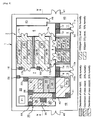
- Fig 1 shows an embodiment of plant factory 1 according to the present invention for manufacturing foodstuffs and/or pharmaceuticals containing raw functional materials using transgenic plants P, such as transgenic strawberry.
- the factory 1 includes three areas, i.e. a closed cultivation area 2 for cultivating transgenic plants P hydroponically, a manufacturing area 30 for processing post-harvest plants P into foodstuffs and/or pharmaceuticals, and a inactivation area 20 located between two areas 2 and 30 for inactivating the post-harvest plants P.
- the cultivation area 2 and the inactivation area 20 are communicating by air-locked passage 22, e. g.
- air-locked pass-box located on partition wall between them for passing post-harvest plants P, and the inactivation area 20 and the manufacturing area 30 are communicating by air-locked passage 38, e.g. air-locked pass-box located on partition wall between them for passing the post-harvest plants P, so as to transfer transgenic plants P along such a designated flow path as black arrows shown in Fig 1 .
- the cultivation area 2 and the manufacturing area 30 are provided with their respective air-locked workers' entrances 10, 39 and exits 14, 35, e.g. air-locked antechamber 10, 39 with or without air-shower and post-chamber 14, 35 passed through for entering and exiting, so as to prohibit workers' traveling between the cultivation area 2 and the manufacturing area 30 as white arrows shown in Fig 1 .
- Fig 1 workers' travelling between the cultivation area 2 and the inactivating area 20 is permitted through air-locked gateway 23, e.g. air-locked chamber located on partition wall between them, but workers' traveling between them may be prohibited in case the inactivation area 20 is provided with its own air-locked workers' gateway (not depicted in Fig 1 ) separately from the workers' entrance 10 and exit 14 of the cultivation area 2.
- air-locked gateway 23 e.g. air-locked chamber located on partition wall between them, but workers' traveling between them may be prohibited in case the inactivation area 20 is provided with its own air-locked workers' gateway (not depicted in Fig 1 ) separately from the workers' entrance 10 and exit 14 of the cultivation area 2.
- the closed cultivation area 2 includes four cultivation chambers 3A, 3B, 3C, 3D with equipped their respective hydroponic systems 4A, 4B, 4C, 4D and air-conditioners 5A, 5B, 5C, 5D.
- each of hydroponic systems 4A, 4B, 4C, 4D is connected to a drainage sterilizer 60 (as shown in Fig 6 ) and each of air-conditioners 5A, 5B, 5C, 5D includes exhaust air-filter 71 (as shown in Fig 7 ).
- Hydroponics also known as nutriculture is a cultivation system of plants using water solution or fluid culture of nutrient, e.g. mineral salts, instead of soil, as described in detail on [non-patent literature No.4].
- the hydroponic system 4 may be solution culture system that just use a nutrient solution, e.g. continuous flow solution culture system such as NFT or DFT, static solution culture system etc., or medium culture system that use a nutrient solution with a solid medium, e.g. sand culture system, gravel culture system, rock-wool culture system etc.
- transgenic plants P can be surrounded and cultivated in a porous medium so that leakage of transgenic plants P into the solution may be prevented effectively and the drainage from hydroponic system 4 may be reduced efficiently for lightening the burden on the sterilizer 60.
- each of cultivation chambers 3A, 3B, 3C, 3D may be so designed that inside light condition is controllable with artificial lighting system 26 of variable emission spectrum and light intensity as shown in Fig 4 .
- artificial lighting system is not indispensable for cultivating transgenic plants P.
- the cultivation chambers 3 may be designed to collect natural sunlight in it, or to be switchable of the collecting of the natural sunlight and the use of artificial lighting system 26.
- the cultivation chambers 3A, 3B, 3C, 3D are preferably so controlled separately as to be suitable inside temperature, humidity, airflow and carbon-dioxide level for various transgenic plants P by their respective air-conditioners 5A, 5B, 5C, 5D.
- the cultivation area 2 is not necessary to be divided into several chamber 3 and may be used a single chamber as a whole.
- the cultivation area 2 includes an anterior chamber 6 connected to the air-locked workers' entrance 10 and a posterior chamber 7 connected to the air-locked workers' exit 14, and the cultivation chambers 3A, 3B are located between and connected to the anterior chamber 6 and the posterior chamber 7 via their respective airtight workers' entrance 17a and exit 17b.
- the cultivation workers go into the anterior chamber 6 of the cultivation area 2 through the air-locked entrance 10, after changing into working uniform in a dressing room 9, and enter into either cultivation chamber 3A or 3B through the airtight entrance 17a.
- the workers After work in either cultivation chambers 3A or 3B, the workers go out to the posterior chamber 7 through the airtight exit 17b, and leave the cultivation area 2 through the air-locked exit 14 to an undressing room 13 for changing out of uniform.
- the workers' entering flow path into the chambers 3A, 3B and returning flow path from there are planned to avoid crossing each other, risks of contamination and leakage of transgenic plants P incurred by interaction of workers' flow path may be prevented securely, even when different transgenic plants P are cultivated in the chambers 3A, 3B.
- the cultivation area 2 may be provided with a air-locked materials' entrance 12 connected to the anterior chamber 6 and a air-locked materials' exit 16 connected to the posterior chamber 7, similar to the workers' entrance 10 and exit 14, so as to avoid crossing of a materials' entering flow path and exit flow path, in order to prevent contamination and leakage of transgenic plants P incurred by interaction of materials' flow path.
- the posterior chamber 7 may be equipped with a temporary holder, e.g. ultra-deep freezer, of post-harvest transgenic plants P gathered from the cultivation area 2. It is desirable to provide the posterior chamber 7 with a waste disposer, e.g. autoclave, for disposing of and inactivating dead leaves and other waste or debris of the post-harvest plants P, and the inactivated waste may be moved out of the cultivation area 2 through air-locked materials' exit 16 and carrying-out room 15.
- a waste disposer e.g. autoclave
- the closed cultivation area 2 may include a hallway 8 located between and connected to the anterior chamber 6 and the posterior chambers 7 via airtight workers' entrance 17a and exit 17b, and the cultivation chambers 3C, 3D may be located alongside and connected to the hallway 8 via a airtight gateway 17.
- the workers go into either cultivation chamber 3C or 3D from the anterior chamber 6 through the airtight entrance 17a and hallway 8, and go out from the chamber 3C or 3D after work to the posterior chamber 7 through the hallway 8 and airtight exit 17b, as white arrows shown in Fig 1 .
- the workers of the cultivation chamber 3C, 3D may be allowed to travel in one direction from entrance 17a to exit 17b on the hallway 8 in order to avoid interaction of workers' flow path and prevent leakage of transgenic plants P, so that a number of cultivation chambers 3 may be arranged contiguously and closely even when the cultivation area 2 is rather small in area.
- care must be taken for avoiding interaction of workers' flow path since the exit flow path from the cultivation chamber 3C and the entering flow path into cultivation chamber 3D may be crossed.
- the inactivation area 20 is located next and connected to the posterior chamber 7 of cultivation area 2 via air-locked passage 22 and air-locked gateway 23, and equipped with inactivation system 21.
- the workers go into the inactivation area 20 from the posterior chamber 7 through the air-locked gateway 23, and after work return to the posterior chamber 7 through the gateway 23 and leave there through the air-locked exit 14, as white arrows shown in Fig 1 .
- Post-harvest transgenic plants P are transferred from the cultivation area 2 into the inactivation area 20 through the air-locked passage 22.
- the inactivation system 21 provides a process of rendering the post-harvest plants P inactive such that plants P does not sprout, grow, proliferate or hybridize under the natural environment while retaining and keeping functional activity of inside materials, e.g.
- the inactivation system 21 may be selected from the group consisting of freeze-drying device, grinder, heater and chemical treatment device. As shown in experimental examples 1 and 2 below, transgenic plants P are deprived of sprouting ability of the seeds by freeze-drying process while retaining functional activity of the gene products. Similarly, grinding process, heating process and chemical treating process also deprive transgenic plants P of sprouting, growing, proliferating or hybridizing ability while retaining functional activity of the gene products, on condition that grinding size, heating temperature and chemical varieties are suitably selected with transgenic plants P based on experiments.
- Transgenic strawberry into which introduced IFN- ⁇ gene was cultivated, and post-harvest fruits were preserved in refrigerator at -80°C for saving up enough amount to experiment.
- Preserved fruits were inactivated by freeze-drying device (RLEII made by KYOWA VACUUM TECHNOLOGY K. K. in Japan) and packed in sealed container and kept at desiccator.
- RLEII freeze-drying device
- healthy 500 seeds were picked up from the freeze-dried fruits by tweezers and, after sterilized by soaking in 1% solution of sodium hypochlorite for 15 minutes followed by rinsing with distilled water three times, scattered in 20 sheets of wetted filter-paper on Petri dish of 9cm in diameter with 25 seeds each.
- Fig 8 shows the result of this experiment that blood IL6 level was decreased more significantly in mice fed with LF strawberry than mice fed with C strawberry.
- the manufacturing area 30 includes a processing chamber 31 being connected to the inactivation area 20 via air-locked passage 38, an anterior chamber 33 connecting to the processing chamber 31 via airtight gateway 31a, a preparing chamber 32 connecting to the anterior chamber 33 via airtight gateway 32a, and an arranging chamber 37 connecting to the anterior chamber 33 via air-locked passage 40.
- the air-locked entrance 39 and exit 35 to the manufacturing area 30 are provided at the anterior chamber 33.
- the manufacturing workers go into a dressing room 34 for changing into working uniform (e.g. dust-free clothes) through entrance room 36, and enter into either the processing chamber 31 or the preparing chamber 32 through the air-locked entrance (e.g.
- the workers go out and leave to the entrance room 36 through the anterior chamber 33 and the air-locked exit 35.
- the air-locked exit 35 may be served as undressing chamber for changing out of uniform.
- the dressing room 34 may be equipped with hand-wash device 33a so as to make workers wash their hands before air-shower in the entrance 39 and entering into the anterior chamber 33.
- the airtight gateway 31a, 32a of the processing chamber 31 and preparing chamber 32 may be replaced with air-locked gateway, e.g. air-locked antechamber passed through for entering and exiting, in case the manufacturing area 30 has enough space affording to them.
- the processing chamber 31 is equipped with processing system 42 for processing transgenic plants P into foodstuffs and/or pharmaceuticals for various uses, and the preparing chamber 32 is equipped with preparing system 43 for preparing the foodstuffs and/or pharmaceuticals for specialized use, e.g. medical or industrial uses.
- the processing system 42 may be a pulverizing or crushing device, e.g. mixer, for reducing or shaping transgenic plants P into powder or tablet form for foodstuffs and/or pharmaceuticals.
- the processing system 42 may be those for taking the raw functional materials out of transgenic plants P, e.g. chromatography system, ultracentrifuge system etc.
- the preparing system 43 may be an encapsulating device for enclosing the raw functional materials took out by the processing system 42 in a small container, e.g. capsule or ampoule, with or without additives such as stabilizer, so as to make the raw functional materials more usable and accessible foodstuffs and/or pharmaceuticals.
- the preparing chamber 32 may be controlled at a specified air-pressure and cleanliness as described below, and the preparing system 43 may includes a clean booth or bench for germ-free operation so as to prepare the drug or reagents using crude material, i.e. raw functional materials extracted or purified out of transgenic plants P, without contamination.
- Fig 2 shows an embodiment of atmospheric pressure control of the closed cultivation area 2, the inactivation area 20 and the manufacturing area 30 in the plant factory 1.
- the cultivation chambers 3A, 3B, 3C, 3D in cultivation area 2, the inactivation area 20 and the manufacturing area 30 may be in independent control from each other of their respective air-conditioner, but the inactivation area 20 and the manufacturing area 30 may be controlled integrally with single air-conditioner.
- the cultivation chambers 3A, 3B, 3C, 3D may be controlled to be kept at the same negative pressure lower than the ambience so as to make airflow from outside to inside of each cultivation chamber 3A, 3B, 3C, 3D through airtight gateway 17a, 17b, and 17.
- the inactivation area 20 may be controlled to be kept at negative pressure less strong than that at the cultivation area 2 so as to make airflow from the inactivation area 20 to the cultivation area 2 through the air-locked passage 22 and gateways 23.
- the manufacturing area 30 may be controlled to be kept at positive pressure higher than the ambience.
- the processing chamber 31 and the dressing room 34 is kept at positive gauge pressure of 15Pa
- the anterior chamber 33 is kept at gauge pressure of 30Pa
- the preparing chamber 32 is kept at gauge pressure of 45Pa so as to make suitable airflow within the manufacturing area 30, i.e. airflow from the preparing chamber 32 to the processing chamber 31 and the dressing room 34 through the anterior chamber 33.
- the arranging chamber 37 in the manufacturing area 30 may be kept at gauge pressure of 10Pa so as to allow airflow from the anterior chamber 33 to the arranging chamber 37.
- the entrance room 36 may be kept at gauge pressure of 5Pa so as to generate airflow from the dressing room 34 and undressing chamber 35 to the entrance room 36.
- Fig 3 shows an embodiment of cleanliness control of the manufacturing area 30 and carbon-dioxide control of the closed cultivation area 2 in the plant factory 1.
- the preparing chamber 32 in the manufacturing area 30 is controlled at high cleanliness of class 1000 (i.e. the number of particles of specified size or larger per cubit feet volume of air is less than 10 3 ), whereas the processing chamber 31, anterior chamber 33 and dressing room 34 are controlled at cleanliness of class 10000 (the number of particles per volume of air is less than 10 4 ), so as to configure high-class clean area 32 being surrounded with middle-class clean area 31, 33 and 34.
- the arranging chamber 37 and the entrance room 36 may be controlled at cleanliness of class 100000 (the number of particles per volume of air is less than 10 5 ) so as to configure middle-class clean area 31, 33 and 34 being surrounded with low-class clean area 36 and 37.
- the layout of surrounding the high-class clean area, i.e. the preparing chamber 32, with middle-class clean area prohibits worker's traveling and materials' transfer directly from low-class clean area to high-class area beyond middle-class area, and secures cleanliness and safety of foodstuffs and/or pharmaceuticals manufactured in the preparing chamber 32 and the processing chamber 31 without risks of pollution or contamination.
- the preparing chamber 32 is provided with clean booth or clean bench for germ-free operation, e.g.
- the arranging chamber 37 with sterilizer for cleaning instruments of germ-free operation, e.g. steam autoclave, and air-locked passage leading to the preparing chamber 31 in order to transfer the instruments from the arranging chamber 37, i.e. low-class clean area, to the preparing chamber 32, i.e. high-class clean area, with the aid of the sterilizer and air-lock passage.
- Used instruments in the preparing chamber 32 may be returned to the arranging chamber 37 through the anterior chamber 33 and the air-locked passage 40.
- the cultivation chambers 3A, 3C and 3D in the closed cultivation area 2 are controlled at 1,000ppm carbon-dioxide level (CO 2 concentration level), 70% humidity, 25-30°C daytime temperature and 20-25°C nighttime temperature, whereas the cultivation chamber 3B is controlled at 800ppm carbon-dioxide (CO 2 ) level, 70% humidity, 25-30°C daytime temperature and 20-25°C nighttime temperature by their respective air-conditioners 5A, 5B, 5C, 5D.
- Fig 7 shows a preferred system of the air-conditioner 5 in each cultivation chamber 3.
- the air-conditioner 5 may include intake air-filter 70 for introducing outside air; temperature controller 72, humidity controller 73, carbon-dioxide (CO 2 ) controller 74 and airflow controller 75 for adjusting temperature, humidity, CO 2 level and airflow of the air introduced; and exhaust air-filter 71 including pre-filter (shown as PH) and HEPA filter (i.e. High Efficiency Particulate Air Filter, 99.97%, shown as HF).
- the temperature controller 72 and the humidity controller 73 have their respective sensors 72a, 73a for measuring temperature and humidity in the cultivation chamber 3, and control the introduced air at suitable temperature and humidity for supplying to air-inlet 76 of the cultivation chamber 3 based on the output of sensors 72a, 73a.
- the CO 2 controller 74 includes sensor 74a for measuring CO 2 level in the cultivation chamber 3 and carbon-dioxide (CO 2 ) generator 78, and controls valve 78a of the generator 78 on-off for adjusting the introduced air at suitable CO 2 level for supplying to the cultivation chamber 3.
- the airflow controller 75 includes adjustment switch 75a, and controls airflow of the air-conditioner 5 for generating suitable distribution of wind and temperature in cultivation chamber 3 based on the input of the switch 75a.
- the air-conditioners 5A, 5B, 5C, 5D may be separately controlled in accordance with species of transgenic plants P in the cultivation chamber 3A, 3B, 3C, 3D, and provide suitable growth conditions for various plants P by adjusting temperature, humidity, carbon-dioxide level and airflow in the cultivation chamber 3A, 3B, 3C, 3D.
- Transgenic plants P are brought in the cultivation area 2 as seeds or materials from unpacking room 11 through the air-locked entrance 12, and planted in either cultivation chambers 3A, 3B, 3C, 3D under suitable growth condition of light, temperature, humidity, airflow and carbon-dioxide level.
- Post-harvest transgenic plants P are transferred from the cultivation chambers 3A, 3B, 3C, 3D to the inactivation area 20 through the air-locked passage 22 at the posterior chamber 7, and put to the inactivation system 21 suitably adjusted to plants P, e.g. freeze-drying device, grinder, heater, chemical treatment device etc.
- the inactivated post-harvest plants P by the system 21 are transferred to the processing chamber 31 in the manufacturing area 30 through air-locked passage 38, and reduced into power or tablet for foodstuffs and/or pharmaceuticals by the processing system 42, e.g. mixer, in case transgenic plants P are edible as it is.
- the inactivated plants P may be divided and purified into the raw functional materials for pharmaceuticals by the processing system 42, e.g. chromatography system or ultracentrifuge system.
- the raw functional material purified in the processing chamber 31 are transferred to the preparing chamber 32 through the anterior chamber 33, and enclosed in capsule or ampoule with additives as pharmaceuticals for medical or industrial use.
- the foodstuffs processed in the processing chamber 31 may be transferred to the preparing chamber 32 and packaged up using preparing system 43.
- the foodstuffs and/or pharmaceuticals processed or prepared in the processing chamber 31 or preparing chamber 32 are transferred into the arranging chamber 37 through the air-locked passage 40 at the anterior chamber 33, and given arrangement for shipping out from the plant factory 1.
- foodstuffs and/or pharmaceuticals are cleaned and wrapped in the arranging chamber 37 and transferred to shipping area (not depicted in Fig 1 ) through air-locked gateway 41 for carrying out from the factory 1.
- wrapping materials may be brought into the arranging chamber 37 in advance of shipping-out of the foodstuffs and/or pharmaceuticals.
- the foodstuffs and/or pharmaceuticals may be sampled from the arranging chamber 37 to testing chamber (not depicted in Fig 1 ) for quality testing, and transferred to shipping area after quality is confirmed.
- Plant factory 1 of this invention is so designed to inactivate transgenic plants P before passing from the closed cultivation area 2 to the manufacturing area 30, to control inside air pressure for generating airflow from the manufacturing area 30 to the cultivation area 2, and to prohibit workers' traveling between the cultivation area 2 and the manufacturing area 30, and then transgenic plants P can be cultivated and turned into foodstuffs and/or pharmaceuticals while containing them securely within the factory 1.
- the cultivation area 2 may include a plurality of cultivation chamber 3A, 3B, 3C, 3D where growth conditions are controllable separately with respect to light, temperature, humidity, carbon-dioxide level and airflow, more than one transgenic plants P may be cultivated simultaneously and used together for producing various foodstuffs and/or pharmaceuticals. Therefore, it is expected that commercial production of raw functional materials for foodstuffs and/or pharmaceuticals using transgenic plants P will be developed and become more advanced by this invention.
- the object of this invention namely the provision of a plant factory for cultivating transgenic plants and manufacturing foodstuffs and/or pharmaceuticals from them as well as keeping them inside has been fulfilled.
- Fig 4 shows a cross-sectional view of the plant factory 1 at line IV-IV in Fig 1 .
- the cultivation chambers 3A, 3B, 3C, 3D may be designed to intercept natural sunlight and use totally artificial lighting for controlling inside light conditions.
- Each of cultivation chambers 3A, 3B, 3C, 3D includes wholly transparent ceiling board 27, airtight lighting box 25 attached on the ceiling board 27, and heat-exhauster 28 of the lighting box 25 as shown schematically in Fig 7 .
- the artificial lighting system 26 may be equipped within the lighting box 25 and adjusted at suitable light emission spectrum and intensity for growing condition of transgenic plants P. In case transgenic plants P require high-intensity light, e.g.
- the artificial lighting system 26 may be ceramic metal halide lamp system for producing high-intensity powerful output for the size.
- the condition in lighting box 25 can be controlled by the heat-exhauster 28 independently from the condition in cultivation chamber 3 by its air-conditioner 5.
- the heat-exhauster 28 may includes exhaust air-filter 80, intake air-filter 81 and temperature controller 82, and introduces outside air into the lighting box 25 through its air-inlet 84 connecting to the inlet air-filter 81, and removes air inside the lighting box 25 through its air-outlet 85 connecting to the exhaust air-filter 80 for cooling the inside.
- the temperature controller 82 may include sensor 82a for measuring temperature in the lighting box 25, and controls an exhaust fan 83 based on the output of the sensor 83a at suitable introducing airflow for cooling the inside of lighting box 25 since the airflow needs to be varied with temperature of the air.
- the cultivation chamber 3 may be designed to have no window or only window with blinds that permit to observe the inside but curtains the light from outside except observation.
- Fig 5 shows an embodiment of water supply and drainage system in the plant factory 1.
- the system may include a plurality of reservoirs 54A, 54B, 54C, 54D for the respective cultivation chamber 3A, 3B, 3C, 3D, and drainage sterilizer 60.
- the reservoirs 54A, 54B, 54C, 54D are supplied with water from a well 50 near the plant factory 1 and provide the water to the hydroponic systems 4A, 4B, 4C, 4D in cultivation chambers 3A, 3B, 3C, 3D.
- the drainage out of hydroponic systems 4A, 4B, 4C, 4D may be collected to a drainage pit 57, and released to drainageway after disposed by the sterilizer 60 with suitable sterilizing process for inactivating transgenic plant P, e.g.
- the sterilizer 60 may be designed to inactivate pollen and other organ/tissue of transgenic plants P in drainage so as to prevent leakage of transgenic plants P through drainage.
- the sterilizers 60 may be located at each of respective hydroponic system 4A, 4B, 4C, 4D as a part of it, or alternatively may be located apart from them for sterilizing unified drainage from them.
- the reservoirs 54A, 54B, 54C, 54D may include solution preparing mechanism for providing such water solution that prepared with water by dissolving oxygen and adding suitable nutrients for transgenic plants P in the hydroponic systems 4A, 4B, 4C, 4D.
- the reservoirs 54A, 54B, 54C, 54D include solution controlling system that select kind and volume of nutrients suitable for the species of plants P, and provide measures for preventing disease or blight of plants P.
- the hydroponic system 4 may include drainage circulation line (not depicted in Fig 5 ) for returning the drainage out of the system 4 to the reservoir 54 so as to reuse the drainage as supplying water.
- water softening device 52 and water deionization device 53 may be provided between the well 50 and supply tanks 54A, 54B, 54C, 54D as shown in Fig 5 .
- the well water may also be supplied to the air-conditioners 5A, 5B, 5C, 5D in the cultivation chambers 3A, 3B, 3C, 3D, further to the inactivation area 20 and the manufacturing area 30. Drainage out of there may be collected to the drainage pit 57 and disposed by the sterilizer 60 together with the drainage out of hydroponic systems 4A, 4B, 4C, 4D, however, the drainage out of inactivation area 20 and manufacturing area 30 are able to be released to drainageway directly without sterilizing process of sterilizer 60.
- Fig 6 shows another embodiment of water supply and drainage system in the plant factory 1 in which the cultivation chambers 3A, 3B, 3C, 3D are provided with water channels 65A, 65B, 65C, 65D to lead drainage from the air-conditioners 5A, 5B, 5C, 5D to their respective hydroponic systems 4A, 4B, 4C, 4D.
- the cultivation chambers 3A, 3B, 3C, 3D may be controlled at around 70% humidity by air-conditioners 5A, 5B, 5C, 5D, and the drainage out of air-conditioners 5A, 5B, 5C, 5D and the condensed dew in cultivation chambers 3A, 3B, 3C, 3D may contain pollen or other organ/tissue of transgenic plants P and need to be inactivated by the sterilizer 60 before releasing. It is desirable to reduce the drainage volume out of plant factory 1, i.e. the burden on the sterilizer 60, to achieve commercial advantage of production of raw functional materials using transgenic plants P as well as to improve efficiency of containment of transgenic plants P within the factory 1.
- the drainage from air-conditioners 5A, 5B, 5C, 5D are retuned to the reservoirs 54A, 54B, 54C, 54D by the water channels 65A, 65B, 65C, 65D, and can be reused or recycled as supplying water to the cultivation chambers 3A, 3B, 3C, 3D, and therefore the drainage volume may be reduced efficiently without losing effectiveness of containment of transgenic plants P within the factory 1.
- the condensed dew in the cultivation chambers 3A, 3B, 3C, 3D may also lead to the reservoirs 54A, 54B, 54C, 54D by the water channels 65A, 65B, 65C, 65D, and be reused or recycled together with the drainage from air-conditioners 5A, 5B, 5C, 5D.
- Fig 5(B) shows an embodiment of the reservoir 54 that stores the drainage from air-conditioner 5 together with water from the deionization device 53, i.e. the well water, and allows only overflowing water to discharge to the drainage pit 57 for sterilization.
Landscapes
- Life Sciences & Earth Sciences (AREA)
- Environmental Sciences (AREA)
- Engineering & Computer Science (AREA)
- Architecture (AREA)
- Botany (AREA)
- Civil Engineering (AREA)
- Structural Engineering (AREA)
- Hydroponics (AREA)
- Greenhouses (AREA)
- Cultivation Of Plants (AREA)
Abstract
Description
- This invention relates to a transgenic plant factory, more specifically a factory for cultivating transgenic plants modified to produce raw functional materials that plants originally do not produce, e.g. animal protein, vaccine etc., and turning the plants after harvest into such useful products as foodstuffs, pharmaceuticals and/or industrial reagents (hereinafter, these products may be inclusively referred to as "foodstuffs and/or pharmaceuticals").
- The recombinant DNA technology developed in 1980s made it possible to introduce useful genes and traits selectively into plants beyond species barrier or from entirely different kingdoms, and contributed to developments of plant breeding in agriculture. For example, disease-resistant or herbicide-tolerant transgenic crops such as soybean, corn, rape, cotton and potato have been developed using recombinant technology and put to commercial use for the purpose of labor-saving and cost-saving in agriculture. Further as shown in [non-patent literature No.1], crops being tolerate stressful environments by introducing stress-tolerant traits, e.g. drought-resistant or salinity-resistant genes, and corps for malnourished humans or animals by introducing nutrition-rich traits, e.g. genes of high productivity of oleic acid or beta-carotene, have been developed.
- In recent years, transgenic recombinant plants are expected to go beyond plant breeding in agriculture and become effective means of producing raw functional materials for pharmaceuticals, e.g. human or animal drug for peroral administration, topical treatment and diagnoses etc. For example, [non-patent literature No.2] discloses a method of producing anti-viral material IFN-α, i.e. human-interferon-α, using transgenic plants such as tobacco, potato and strawberry into which anticancer gene IFN-α is introduced and expressed. According to this method, it would be possible to manufacture raw functional materials such as IFN-α by extracting and/or purifying gene products out of harvested transgenic plants or its specified organ/tissue (hereinafter referred to as "post-harvest plants") more effectively in quantity and in cost than by the conventional method.
- Further, [patent literature No.1] discloses a peroral carrier system for transporting a functional immunogenic peptide orally to a target site in a living body, e.g. peroral vaccine system, using transgenic plants in which a fused gene obtained by fusing of the functional peptide gene with a Norwark virus (NLV) coat protein gene is introduced. It is reported that, for the purpose of preventing leucocytozoon disease of chickens, a hemorrhagic and anemic disease of chickens to be caused by infection with the hemosporidium (protozoan) Leucocytozoon caulleryi, experimental chickens were provided by oral administration with foodstuffs including post-harvest transgenic potato leaves into which introduced antigen LRE1 gene, i.e. gene for immunogenic LRE1 protein derived from Leucocytozoon caulleryi 2nd-generation schizont, and confirmed that antibody titer to Leucocytozoon caulleryi in blood of the chickens rose after completion of oral administration and become greater than that with no administration of transgenic potato leaves.
- The advantages of producing process of raw functional materials using transgenic plants over conventional bio-process using cultured animal cell and/or other synthesis system are that (i) a larger scale production of the material is possible at lower cost, (ii) a risk of pollution or contamination of the material is minimized with germs or bacteria, e.g. pathogen microbe, and (iii) a long-term preservation of the material is possible at room temperature as plant seeds. Other advantages include that transgenic plants may be processed into foodstuffs, e.g. the aforementioned peroral vaccine, that can be took to patients orally without physical stresses such as intramuscular injection, resulting in reduction of medical waste such as syringes and needles. Transgenic plants may be edible as it is or eatable by reducing to powder, and processed into foodstuffs and/or pharmaceuticals without costly process of extraction and/or purification. Further, producing process using transgenic plants is not only worthwhile to produce products of the introduced gene, e. g. protein, vaccine etc, but also brings forth various chemical products, inclusive of non-protein products, by enzymatic reaction of the introduced enzyme gene.
-
- PATENT LITERATURE
[Patent literature No.1]
Japanese Patent Laying-open Publication No.2005-341937 - NON PATENT LITERATURE
[Non-patent literature No.1]
Japanese Society for Techno-innovation of Agriculture, Forestry and Fisheries, "Summary of Development of transgenic crops and foodstuff" October 2006, see <http://www.biotech-house.jp/qanda/> - [Non-patent literature No.2]
Ken Matsumura, "Closed system for manufacturing useful materials using transgenic plants" 16th SHITA Symposium, SHATA Report No.23, January 18, 2006, pp59-65 - [Non-patent literature No.3]
Japanese Ministry of Education, Culture, Sports, Science and Technology and Japanese Ministry of the Environment, "Ministry ordinance regarding nonproliferation measures in research and development of gene modified living matter", January 29, 2004 - [Non-patent literature No.4]
Tadashi Ito et al., "Olericulture" published by Kawashima Publishing, 4th Edition, May 20, 1994, pp 226-230 - For promoting commercial production of raw functional materials using transgenic plants, a facility is required for cultivating transgenic plants efficiently without harmful effect on environment. At the present time, commercial cultivation of transgenic crops rests on the premise that, after experiments in a laboratory, they are cultivated massively in an open field, i.e. open system. However, transgenic plants for producing raw functional materials are not required to cultivate as massive as the crops, and may be cultivated in a factory of relatively small scale when feasible indoor cultivation technique is available. For example, the aforementioned transgenic plants for producing anti-viral material IFN-α may require 100 square meters (= 1 are) in area at most for commercial scale cultivation. In addition, cultivation of transgenic plants in a factory is advantageous for quality and yield uniformity of the products.
- In case transgenic plants are cultivated in a factory without harmful effect on environment, the factory is required to keep pollen and other plant organ/tissue as well as plant body within it, i.e. to be closed system. [Non-patent literature No.3] discloses a prior art for containing transgenic plants within a laboratory-scale facility. The prior art, however, is not applicable to a factory-scale facility where transgenic plants are not only cultivated but also processed into foodstuffs and/or pharmaceuticals for commercial use, and does not contain transgenic plants efficiently within a factory-scale facility. Mail-sterile plants may be used for the purpose of avoiding leakage of pollen, however, it is not a perfect solution to avoid leakage of transgenic plants since plants may regenerate through other organ/tissue than pollen. For promoting commercial production of raw functional materials using transgenic plants, it is necessary to develop a closed plant factory for cultivating transgenic plants and manufacturing post-harvest plants into foodstuffs and/or pharmaceuticals while containing them within it.
- It is therefore an object of this invention to provide a plant factory for cultivating transgenic plants and manufacturing foodstuffs and/or pharmaceuticals from them as well as keeping them inside.
- Referring to
Fig 1 , the present invention provides a transgenic plant factory (1) comprising a closed cultivation area (2) being kept at negative pressure and equipped with hydroponic system (4) for cultivating transgenic plants (P) and air-conditioner (5) with exhaust air-filter (71); an inactivation area (20) located next to the cultivation area (2) via air-locked passage (22), which inactivation area (20) being kept at negative pressure less strong than that at the cultivation area (2) and equipped with inactivation system (21) to prevent post-harvest transgenic plants (P) from sprouting, growing, proliferating or hybridizing; a manufacturing area (30) located next to the inactivation area (20) via air-locked passage (38), which manufacturing area (30) being kept at positive pressure and equipped with system (42, 43) for processing and/or preparing the post-harvest plants (P) into foodstuffs and/or pharmaceuticals; a sterilizer (60) for sterilizing the drainage from cultivation area (2); and air-locked workers' gateways (10, 14, 39, 35) provided to the cultivation area (2) and the manufacturing area (30) respectively. - Preferably, the closed cultivation area (2) includes air-locked workers' entrance (10) and exit (14) separately located with each other, an anterior chamber (6) connected to the entrance (10), a posterior chamber (7) connected to the exit (14) and located next to the inactivation area (20) via air-locked passage (22), and a plurality of cultivation chambers (3A, 3B) located between and connected to the anterior and posterior chambers (6, 7) via airtight gateway (17a, 17b), wherein the cultivation chambers (3A, 3B) are equipped with their respective hydroponic system (4A, 4B). Additionally or alternatively, the closed cultivation area (2) may include a hallway (8) located between and connected to the anterior and posterior chambers (6, 7) via airtight gateway (17a, 17b), and a plurality of cultivation chambers (3C, 3D) located alongside and connected to the hallway (8) via airtight gateway (17), wherein the cultivation chambers (3C, 3D) are equipped with their respective hydroponic system (4C, 4D).
- More preferably, as shown in
Fig 5 andFig 6 , the cultivation chambers (3A, 3B, 3C, 3D) include their respective air-conditioner (5A, 5B, 5C, 5D) with exhaust air-filter (71) and water channel (65A, 65B, 65C, 65D) to lead drainage from the air-conditioners (5A, 5B, 5C, 5D) to their respective hydroponic system (4A, 4B, 4C, 4D). As shown inFig 7 , each of air-conditioners (5A, 5B, 5C, 5D) may includes a controller (74) for controlling carbon-dioxide (CO2) in the cultivation chamber (3A, 3B, 3C, 3D). As shown inFig 4 andFig 7 , each of cultivation chamber (3A, 3B, 3C, 3D) may includes wholly transparent ceiling board (27), airtight lighting box (25) attached on the ceiling board (27) and heat-exhauster (28) of the lighting box (25). - Desirably, the manufacturing area (30) includes a processing chamber (31) connected to the inactivation area (20) via air-locked passage (38), an anterior chamber (33) connecting to the processing chamber (31) and being kept at positive pressure more strong than that at the processing chamber (31), and a preparing chamber (32) connecting to the anterior chamber (33) and being kept at positive pressure more strong than that at the anterior chamber (33), wherein the air-locked workers' gateway (39, 35) is provided at the anterior chamber (33). The manufacturing area (30) may further include an arranging chamber (37) connecting to the anterior chamber (33) via air-locked passage (40).
- With the present invention, a transgenic plant factory (1) is provided with a closed cultivation area (2) being kept at negative pressure, an inactivation area (20) located next to the cultivation area (2) and being kept at negative pressure less strong than that at the cultivation area (2), and a manufacturing area (30) located next to the inactivation area (20) and being kept at positive pressure, such that transgenic plants (P) are cultivated in the closed cultivation area (2) and gathered through the inactivation area (20) into the manufacturing area (30) for processing and/or preparing into foodstuffs and/or pharmaceuticals. As a result, the following outstanding effects can be achieved.
-
- 1) As transgenic plants (P) are inactivated in the inactivation area (20) before passing to the manufacturing area (30), transgenic plants (P) do not sprout, grow, proliferate nor hybridize in the manufacturing area (30) or in natural environment after shipping out from it, resulting in containment of transgenic plants (P) within the factory (1).
- 2) As air pressure in the factory (1) is so controlled as to make airflow from the manufacturing area (30) to the closed cultivation area (2) through the inactivation area (20), pollen or other organ/tissue of transgenic plants (P) is prohibited from leaking out of the cultivation area (2).
- 3) As workers' access to the factory (1) may be restricted to the workers' gateway (10, 14, 39, 35) so as to prohibit workers' travelling between the cultivation area (2) and the manufacturing area (30), leaking of pollen or other organ/tissue of transgenic plants (P) by adhering to workers' clothing is prevented.
- 4) In case the closed cultivation area (2) includes a plurality of cultivation chambers (3A, 3B, 3C, 3D) with their respective hydroponic system (4A, 4B, 4C, 4D) and air-conditioner (5A, 5B, 5C, 5D), more than one transgenic plants (P) may be cultivated simultaneously without contamination each other and manufactured together into foodstuffs and/or pharmaceuticals .
- 5) In case the manufacturing area (30) includes a preparing chamber (32) being kept at positive pressure more strong than that at other chambers in the area (30), it may be possible to prepare high-qualified pharmaceuticals from transgenic plants (P) by avoiding influence from other areas or chambers without risks of contamination or pollution.
- 6) The factory (1) is a simple structure and may be constructed at small empty space in urban area near the market without harmful effect on environment, so that commercial production of the foodstuffs and/or pharmaceuticals using transgenic plants (P) will be developed by the factory (1).
-
Fig 1 shows an embodiment ofplant factory 1 according to the present invention for manufacturing foodstuffs and/or pharmaceuticals containing raw functional materials using transgenic plants P, such as transgenic strawberry. Thefactory 1 includes three areas, i.e. a closedcultivation area 2 for cultivating transgenic plants P hydroponically, amanufacturing area 30 for processing post-harvest plants P into foodstuffs and/or pharmaceuticals, and ainactivation area 20 located between twoareas cultivation area 2 and theinactivation area 20 are communicating by air-lockedpassage 22, e. g. air-locked pass-box located on partition wall between them for passing post-harvest plants P, and theinactivation area 20 and themanufacturing area 30 are communicating by air-lockedpassage 38, e.g. air-locked pass-box located on partition wall between them for passing the post-harvest plants P, so as to transfer transgenic plants P along such a designated flow path as black arrows shown inFig 1 . Further, thecultivation area 2 and themanufacturing area 30 are provided with their respective air-locked workers'entrances exits antechamber cultivation area 2 and themanufacturing area 30 as white arrows shown inFig 1 . InFig 1 , workers' travelling between thecultivation area 2 and the inactivatingarea 20 is permitted through air-lockedgateway 23, e.g. air-locked chamber located on partition wall between them, but workers' traveling between them may be prohibited in case theinactivation area 20 is provided with its own air-locked workers' gateway (not depicted inFig 1 ) separately from the workers'entrance 10 andexit 14 of thecultivation area 2. - In
Fig 1 , the closedcultivation area 2 includes fourcultivation chambers hydroponic systems conditioners factory 1 throughhydroponic system 4 and air-conditioner 5, each ofhydroponic systems Fig 6 ) and each of air-conditioners Fig 7 ). Hydroponics (also known as nutriculture) is a cultivation system of plants using water solution or fluid culture of nutrient, e.g. mineral salts, instead of soil, as described in detail on [non-patent literature No.4]. Thehydroponic system 4 may be solution culture system that just use a nutrient solution, e.g. continuous flow solution culture system such as NFT or DFT, static solution culture system etc., or medium culture system that use a nutrient solution with a solid medium, e.g. sand culture system, gravel culture system, rock-wool culture system etc. In case the medium culture system is used, transgenic plants P can be surrounded and cultivated in a porous medium so that leakage of transgenic plants P into the solution may be prevented effectively and the drainage fromhydroponic system 4 may be reduced efficiently for lightening the burden on thesterilizer 60. - In case the
cultivation area 2 includesseveral cultivation chambers cultivation area 2. For providing a suitable light condition for transgenic plants P, each ofcultivation chambers artificial lighting system 26 of variable emission spectrum and light intensity as shown inFig 4 . However, such artificial lighting system is not indispensable for cultivating transgenic plants P. If transgenic plants P can grow under the light of the sun, thecultivation chambers 3 may be designed to collect natural sunlight in it, or to be switchable of the collecting of the natural sunlight and the use ofartificial lighting system 26. Thecultivation chambers conditioners factory 1, thecultivation area 2 is not necessary to be divided intoseveral chamber 3 and may be used a single chamber as a whole. - In preferred embodiment, the
cultivation area 2 includes ananterior chamber 6 connected to the air-locked workers'entrance 10 and aposterior chamber 7 connected to the air-locked workers'exit 14, and thecultivation chambers anterior chamber 6 and theposterior chamber 7 via their respective airtight workers'entrance 17a andexit 17b. As white arrows shown inFig 1 , the cultivation workers go into theanterior chamber 6 of thecultivation area 2 through the air-lockedentrance 10, after changing into working uniform in adressing room 9, and enter into eithercultivation chamber airtight entrance 17a. After work in eithercultivation chambers posterior chamber 7 through theairtight exit 17b, and leave thecultivation area 2 through the air-lockedexit 14 to anundressing room 13 for changing out of uniform. As the workers' entering flow path into thechambers chambers Fig 1 , thecultivation area 2 may be provided with a air-locked materials'entrance 12 connected to theanterior chamber 6 and a air-locked materials'exit 16 connected to theposterior chamber 7, similar to the workers'entrance 10 andexit 14, so as to avoid crossing of a materials' entering flow path and exit flow path, in order to prevent contamination and leakage of transgenic plants P incurred by interaction of materials' flow path. Though not depicted inFig 1 , theposterior chamber 7 may be equipped with a temporary holder, e.g. ultra-deep freezer, of post-harvest transgenic plants P gathered from thecultivation area 2. It is desirable to provide theposterior chamber 7 with a waste disposer, e.g. autoclave, for disposing of and inactivating dead leaves and other waste or debris of the post-harvest plants P, and the inactivated waste may be moved out of thecultivation area 2 through air-locked materials'exit 16 and carrying-out room 15. - Additionally or alternatively, the
closed cultivation area 2 may include ahallway 8 located between and connected to theanterior chamber 6 and theposterior chambers 7 via airtight workers'entrance 17a andexit 17b, and thecultivation chambers hallway 8 via aairtight gateway 17. The workers go into eithercultivation chamber anterior chamber 6 through theairtight entrance 17a andhallway 8, and go out from thechamber posterior chamber 7 through thehallway 8 andairtight exit 17b, as white arrows shown inFig 1 . The workers of thecultivation chamber entrance 17a to exit 17b on thehallway 8 in order to avoid interaction of workers' flow path and prevent leakage of transgenic plants P, so that a number ofcultivation chambers 3 may be arranged contiguously and closely even when thecultivation area 2 is rather small in area. However, when different transgenic plants P are cultivated in thecultivation chambers cultivation chamber 3C and the entering flow path intocultivation chamber 3D may be crossed. - The
inactivation area 20 is located next and connected to theposterior chamber 7 ofcultivation area 2 via air-lockedpassage 22 and air-lockedgateway 23, and equipped withinactivation system 21. The workers go into theinactivation area 20 from theposterior chamber 7 through the air-lockedgateway 23, and after work return to theposterior chamber 7 through thegateway 23 and leave there through the air-lockedexit 14, as white arrows shown inFig 1 . Post-harvest transgenic plants P are transferred from thecultivation area 2 into theinactivation area 20 through the air-lockedpassage 22. Theinactivation system 21 provides a process of rendering the post-harvest plants P inactive such that plants P does not sprout, grow, proliferate or hybridize under the natural environment while retaining and keeping functional activity of inside materials, e.g. the gene products and/or enzymatic reaction products of the gene. Theinactivation system 21 may be selected from the group consisting of freeze-drying device, grinder, heater and chemical treatment device. As shown in experimental examples 1 and 2 below, transgenic plants P are deprived of sprouting ability of the seeds by freeze-drying process while retaining functional activity of the gene products. Similarly, grinding process, heating process and chemical treating process also deprive transgenic plants P of sprouting, growing, proliferating or hybridizing ability while retaining functional activity of the gene products, on condition that grinding size, heating temperature and chemical varieties are suitably selected with transgenic plants P based on experiments. - Transgenic strawberry into which introduced IFN-α gene (transgenic line of hIFN: IFN62) was cultivated, and post-harvest fruits were preserved in refrigerator at -80°C for saving up enough amount to experiment. Preserved fruits were inactivated by freeze-drying device (RLEII made by KYOWA VACUUM TECHNOLOGY K. K. in Japan) and packed in sealed container and kept at desiccator. In the experiment, healthy 500 seeds were picked up from the freeze-dried fruits by tweezers and, after sterilized by soaking in 1% solution of sodium hypochlorite for 15 minutes followed by rinsing with distilled water three times, scattered in 20 sheets of wetted filter-paper on Petri dish of 9cm in diameter with 25 seeds each. The sheets sown with seeds were left in incubator under control at 24°C and 16 hours day-length, and observed for 12 weeks while wetting the sheets with water periodically whether the seeds were sprouting or not. Similar experiments were performed with different transgenic strawberries into which introduced lactoferrin gene (two lines of LF125 and LF145) and with no-transgenic strawberry (HS-13: Control). Table 1 shows the results of these four experiments that there are no seeds of any transgenic line to sprout in 12 weeks when inactivated.
[Table 1] Line Number of sample Number of sprouting Rate of sprouting (%) Control 500 0 0.0 LF125 500 0 0.0 LF145 500 0 0.0 IFN62 500 0 0.0 - For comparison, similar experiments were performed with seeds collected from freshly harvested fruits of transgenic strawberry LF145 and no-transgenic strawberry HS-13 (Control) except inactivation process. 3 sheets of wetted filter-paper sowed with 25 seeds each were prepared and left in incubator to observe for 12 weeks whether the seeds were sprouting or not. Table 2 shows the result of this experiment that the fresh seeds of any transgenic line have ability to sprout out, though number of experimented transgenic lines is not enough. In comparison with Table 1 and Table 2, it would be concluded that transgenic strawberry is deprived of sprouting ability of the seeds by freeze-drying process.
[Table 2] Line Number of sample Number of sprouting Rate of sprouting (%) Control 75 54 72.0 LF145 75 47 62.7 - For the purpose of confirming that the gene product of transgenic strawberry retains functional activity even after freeze-drying process of Experimental Example 1, further experiments were performed. In this experiment, freeze-dried fruit of transgenic strawberry into which introduced lactoferrin gene (LF strawberry) and freeze-dried fruit of no-transgenic strawberry (C strawberry) were prepared and reduced to powder, and fed to stress-induced immune mice by oral administration, and then blood level of IL6, i.e.
interleukin 6 acting as cytokine, of the mice were measured by ELISA (Enzyme-Linked ImmunoSorbent Assay) method. Five mice under stressed conditions are fed with either of LF strawberry powder or C strawberry powder for one week with one gram (1g) per day, and took a blood sample to test for blood IL6 level. For comparison, similar experiments were performed using mice under normal condition fed with regular food for testing for blood IL6 level of normal mice.Fig 8 shows the result of this experiment that blood IL6 level was decreased more significantly in mice fed with LF strawberry than mice fed with C strawberry. Similar testing of other cytokines, i.e. IL2, IL4, IL12, IL1 β, IFNγ, TNF α, were performed and confirmed that blood cytokine level decrease more significantly in mice fed with LF strawberry than mice fed with C strawberry. From these experiments, it would be concluded that the gene product in transgenic plants P retains functional activity, e.g. lactoferrin activity, even after freeze-drying process, although sprouting ability is deprived of by freeze-drying process as mentioned above. - In
Fig 1 , themanufacturing area 30 includes aprocessing chamber 31 being connected to theinactivation area 20 via air-lockedpassage 38, ananterior chamber 33 connecting to theprocessing chamber 31 viaairtight gateway 31a, a preparingchamber 32 connecting to theanterior chamber 33 viaairtight gateway 32a, and an arrangingchamber 37 connecting to theanterior chamber 33 via air-lockedpassage 40. The air-lockedentrance 39 andexit 35 to themanufacturing area 30 are provided at theanterior chamber 33. The manufacturing workers go into adressing room 34 for changing into working uniform (e.g. dust-free clothes) throughentrance room 36, and enter into either theprocessing chamber 31 or the preparingchamber 32 through the air-locked entrance (e.g. antechamber with air-shower) 39 and theanterior chamber 33 as white arrows shown inFig 1 . After work in eitherprocessing chamber 31 or preparingchamber 32, the workers go out and leave to theentrance room 36 through theanterior chamber 33 and the air-lockedexit 35. The air-lockedexit 35 may be served as undressing chamber for changing out of uniform. As the workers' entering flow path throughdressing room 34 and returning flow path through undressingchamber 35 are separated and do not cross each other, risks of pollution or contamination of the uniform is effectively eliminated. As shown inFig 5 , thedressing room 34 may be equipped with hand-wash device 33a so as to make workers wash their hands before air-shower in theentrance 39 and entering into theanterior chamber 33. Theairtight gateway processing chamber 31 and preparingchamber 32 may be replaced with air-locked gateway, e.g. air-locked antechamber passed through for entering and exiting, in case themanufacturing area 30 has enough space affording to them. - The
processing chamber 31 is equipped withprocessing system 42 for processing transgenic plants P into foodstuffs and/or pharmaceuticals for various uses, and the preparingchamber 32 is equipped with preparingsystem 43 for preparing the foodstuffs and/or pharmaceuticals for specialized use, e.g. medical or industrial uses. In case transgenic plants P are edible as it is without extraction or purification process, e.g. the aforementioned peroral vaccine, theprocessing system 42 may be a pulverizing or crushing device, e.g. mixer, for reducing or shaping transgenic plants P into powder or tablet form for foodstuffs and/or pharmaceuticals. In case raw functional materials is required to extracted or purified from transgenic plants P, theprocessing system 42 may be those for taking the raw functional materials out of transgenic plants P, e.g. chromatography system, ultracentrifuge system etc. The preparingsystem 43 may be an encapsulating device for enclosing the raw functional materials took out by theprocessing system 42 in a small container, e.g. capsule or ampoule, with or without additives such as stabilizer, so as to make the raw functional materials more usable and accessible foodstuffs and/or pharmaceuticals. When human or animal drug or industrial reagents are prepared in themanufacturing area 30, the preparingchamber 32 may be controlled at a specified air-pressure and cleanliness as described below, and the preparingsystem 43 may includes a clean booth or bench for germ-free operation so as to prepare the drug or reagents using crude material, i.e. raw functional materials extracted or purified out of transgenic plants P, without contamination. -
Fig 2 shows an embodiment of atmospheric pressure control of theclosed cultivation area 2, theinactivation area 20 and themanufacturing area 30 in theplant factory 1. Thecultivation chambers cultivation area 2, theinactivation area 20 and themanufacturing area 30 may be in independent control from each other of their respective air-conditioner, but theinactivation area 20 and themanufacturing area 30 may be controlled integrally with single air-conditioner. Thecultivation chambers cultivation chamber airtight gateway inactivation area 20 may be controlled to be kept at negative pressure less strong than that at thecultivation area 2 so as to make airflow from theinactivation area 20 to thecultivation area 2 through the air-lockedpassage 22 andgateways 23. Themanufacturing area 30 may be controlled to be kept at positive pressure higher than the ambiance. In preferred embodiment, theprocessing chamber 31 and thedressing room 34 is kept at positive gauge pressure of 15Pa, theanterior chamber 33 is kept at gauge pressure of 30Pa, and the preparingchamber 32 is kept at gauge pressure of 45Pa so as to make suitable airflow within themanufacturing area 30, i.e. airflow from the preparingchamber 32 to theprocessing chamber 31 and thedressing room 34 through theanterior chamber 33. Further, the arrangingchamber 37 in themanufacturing area 30 may be kept at gauge pressure of 10Pa so as to allow airflow from theanterior chamber 33 to the arrangingchamber 37. Furthermore, theentrance room 36 may be kept at gauge pressure of 5Pa so as to generate airflow from thedressing room 34 and undressingchamber 35 to theentrance room 36. -
Fig 3 shows an embodiment of cleanliness control of themanufacturing area 30 and carbon-dioxide control of theclosed cultivation area 2 in theplant factory 1. In preferred embodiment, the preparingchamber 32 in themanufacturing area 30 is controlled at high cleanliness of class 1000 (i.e. the number of particles of specified size or larger per cubit feet volume of air is less than 103), whereas theprocessing chamber 31,anterior chamber 33 anddressing room 34 are controlled at cleanliness of class 10000 (the number of particles per volume of air is less than 104), so as to configure high-classclean area 32 being surrounded with middle-classclean area chamber 37 and theentrance room 36 may be controlled at cleanliness of class 100000 (the number of particles per volume of air is less than 105) so as to configure middle-classclean area clean area chamber 32, with middle-class clean area prohibits worker's traveling and materials' transfer directly from low-class clean area to high-class area beyond middle-class area, and secures cleanliness and safety of foodstuffs and/or pharmaceuticals manufactured in the preparingchamber 32 and theprocessing chamber 31 without risks of pollution or contamination. In case the preparingchamber 32 is provided with clean booth or clean bench for germ-free operation, e.g. booth or bench at cleanliness of class A under Good manufacturing practice (GMP) of WHO, it is desirable to provide the arrangingchamber 37 with sterilizer for cleaning instruments of germ-free operation, e.g. steam autoclave, and air-locked passage leading to the preparingchamber 31 in order to transfer the instruments from the arrangingchamber 37, i.e. low-class clean area, to the preparingchamber 32, i.e. high-class clean area, with the aid of the sterilizer and air-lock passage. Used instruments in the preparingchamber 32 may be returned to the arrangingchamber 37 through theanterior chamber 33 and the air-lockedpassage 40. - In
Fig 3 , thecultivation chambers closed cultivation area 2 are controlled at 1,000ppm carbon-dioxide level (CO2 concentration level), 70% humidity, 25-30°C daytime temperature and 20-25°C nighttime temperature, whereas thecultivation chamber 3B is controlled at 800ppm carbon-dioxide (CO2) level, 70% humidity, 25-30°C daytime temperature and 20-25°C nighttime temperature by their respective air-conditioners Fig 7 shows a preferred system of the air-conditioner 5 in eachcultivation chamber 3. The air-conditioner 5 may include intake air-filter 70 for introducing outside air;temperature controller 72,humidity controller 73, carbon-dioxide (CO2)controller 74 andairflow controller 75 for adjusting temperature, humidity, CO2 level and airflow of the air introduced; and exhaust air-filter 71 including pre-filter (shown as PH) and HEPA filter (i.e. High Efficiency Particulate Air Filter, 99.97%, shown as HF). Thetemperature controller 72 and thehumidity controller 73 have theirrespective sensors cultivation chamber 3, and control the introduced air at suitable temperature and humidity for supplying to air-inlet 76 of thecultivation chamber 3 based on the output ofsensors sensor 74a for measuring CO2 level in thecultivation chamber 3 and carbon-dioxide (CO2)generator 78, and controls valve 78a of thegenerator 78 on-off for adjusting the introduced air at suitable CO2 level for supplying to thecultivation chamber 3. Theairflow controller 75 includesadjustment switch 75a, and controls airflow of the air-conditioner 5 for generating suitable distribution of wind and temperature incultivation chamber 3 based on the input of theswitch 75a. The air-conditioners cultivation chamber cultivation chamber - Referring to black arrows shown in
Fig 1 , manufacturing process of foodstuffs and/or pharmaceuticals in theplant factory 1 may be described as follows. Transgenic plants P are brought in thecultivation area 2 as seeds or materials from unpackingroom 11 through the air-lockedentrance 12, and planted in eithercultivation chambers cultivation chambers inactivation area 20 through the air-lockedpassage 22 at theposterior chamber 7, and put to theinactivation system 21 suitably adjusted to plants P, e.g. freeze-drying device, grinder, heater, chemical treatment device etc. The inactivated post-harvest plants P by thesystem 21 are transferred to theprocessing chamber 31 in themanufacturing area 30 through air-lockedpassage 38, and reduced into power or tablet for foodstuffs and/or pharmaceuticals by theprocessing system 42, e.g. mixer, in case transgenic plants P are edible as it is. In case extraction or purification process is required, the inactivated plants P may be divided and purified into the raw functional materials for pharmaceuticals by theprocessing system 42, e.g. chromatography system or ultracentrifuge system. The raw functional material purified in theprocessing chamber 31 are transferred to the preparingchamber 32 through theanterior chamber 33, and enclosed in capsule or ampoule with additives as pharmaceuticals for medical or industrial use. Similarly, the foodstuffs processed in theprocessing chamber 31 may be transferred to the preparingchamber 32 and packaged up using preparingsystem 43. - The foodstuffs and/or pharmaceuticals processed or prepared in the
processing chamber 31 or preparingchamber 32 are transferred into the arrangingchamber 37 through the air-lockedpassage 40 at theanterior chamber 33, and given arrangement for shipping out from theplant factory 1. For example, foodstuffs and/or pharmaceuticals are cleaned and wrapped in the arrangingchamber 37 and transferred to shipping area (not depicted inFig 1 ) through air-lockedgateway 41 for carrying out from thefactory 1. As hatching arrows shown inFig 1 , wrapping materials may be brought into the arrangingchamber 37 in advance of shipping-out of the foodstuffs and/or pharmaceuticals. In case quality inspection is required, the foodstuffs and/or pharmaceuticals may be sampled from the arrangingchamber 37 to testing chamber (not depicted inFig 1 ) for quality testing, and transferred to shipping area after quality is confirmed. -
Plant factory 1 of this invention is so designed to inactivate transgenic plants P before passing from the closedcultivation area 2 to themanufacturing area 30, to control inside air pressure for generating airflow from themanufacturing area 30 to thecultivation area 2, and to prohibit workers' traveling between thecultivation area 2 and themanufacturing area 30, and then transgenic plants P can be cultivated and turned into foodstuffs and/or pharmaceuticals while containing them securely within thefactory 1. Further, thecultivation area 2 may include a plurality ofcultivation chamber - Thus, the object of this invention, namely the provision of a plant factory for cultivating transgenic plants and manufacturing foodstuffs and/or pharmaceuticals from them as well as keeping them inside has been fulfilled.
-
Fig 4 shows a cross-sectional view of theplant factory 1 at line IV-IV inFig 1 . Thecultivation chambers cultivation chambers transparent ceiling board 27,airtight lighting box 25 attached on theceiling board 27, and heat-exhauster 28 of thelighting box 25 as shown schematically inFig 7 . Theartificial lighting system 26 may be equipped within thelighting box 25 and adjusted at suitable light emission spectrum and intensity for growing condition of transgenic plants P. In case transgenic plants P require high-intensity light, e.g. transgenic rice, theartificial lighting system 26 may be ceramic metal halide lamp system for producing high-intensity powerful output for the size. As thelighting box 25 is attached to and sealed by thetransparent ceiling board 27, the condition inlighting box 25 can be controlled by the heat-exhauster 28 independently from the condition incultivation chamber 3 by its air-conditioner 5. As shown inFig 7 , the heat-exhauster 28 may includes exhaust air-filter 80, intake air-filter 81 andtemperature controller 82, and introduces outside air into thelighting box 25 through its air-inlet 84 connecting to the inlet air-filter 81, and removes air inside thelighting box 25 through its air-outlet 85 connecting to the exhaust air-filter 80 for cooling the inside. Thetemperature controller 82 may include sensor 82a for measuring temperature in thelighting box 25, and controls anexhaust fan 83 based on the output of the sensor 83a at suitable introducing airflow for cooling the inside oflighting box 25 since the airflow needs to be varied with temperature of the air. In case transgenic plants P need strict light condition without influence from the outside of cultivation chamber, thecultivation chamber 3 may be designed to have no window or only window with blinds that permit to observe the inside but curtains the light from outside except observation. -
Fig 5 shows an embodiment of water supply and drainage system in theplant factory 1. The system may include a plurality ofreservoirs respective cultivation chamber drainage sterilizer 60. For example, thereservoirs plant factory 1 and provide the water to thehydroponic systems cultivation chambers hydroponic systems drainage pit 57, and released to drainageway after disposed by thesterilizer 60 with suitable sterilizing process for inactivating transgenic plant P, e.g. sterilizing process of heating at specified temperature (121°C) during more than specified period (21 minutes). Thesterilizer 60 may be designed to inactivate pollen and other organ/tissue of transgenic plants P in drainage so as to prevent leakage of transgenic plants P through drainage. Thesterilizers 60 may be located at each of respectivehydroponic system reservoirs hydroponic systems reservoirs sterilizer 60, thehydroponic system 4 may include drainage circulation line (not depicted inFig 5 ) for returning the drainage out of thesystem 4 to thereservoir 54 so as to reuse the drainage as supplying water. - In case water from the well 50 is not suitable for transgenic plants P,
water softening device 52 andwater deionization device 53 may be provided between the well 50 andsupply tanks Fig 5 . The well water may also be supplied to the air-conditioners cultivation chambers inactivation area 20 and themanufacturing area 30. Drainage out of there may be collected to thedrainage pit 57 and disposed by thesterilizer 60 together with the drainage out ofhydroponic systems inactivation area 20 andmanufacturing area 30 are able to be released to drainageway directly without sterilizing process ofsterilizer 60. -
Fig 6 shows another embodiment of water supply and drainage system in theplant factory 1 in which thecultivation chambers water channels conditioners hydroponic systems cultivation chambers conditioners conditioners cultivation chambers sterilizer 60 before releasing. It is desirable to reduce the drainage volume out ofplant factory 1, i.e. the burden on thesterilizer 60, to achieve commercial advantage of production of raw functional materials using transgenic plants P as well as to improve efficiency of containment of transgenic plants P within thefactory 1. InFig 6 , the drainage from air-conditioners reservoirs water channels cultivation chambers factory 1. As not depicted inFig 6 , the condensed dew in thecultivation chambers reservoirs water channels conditioners Fig 5(B) shows an embodiment of thereservoir 54 that stores the drainage from air-conditioner 5 together with water from thedeionization device 53, i.e. the well water, and allows only overflowing water to discharge to thedrainage pit 57 for sterilization. -
-
Fig 1 is a schematic view of transgenic plant factory according to this invention. -
Fig 2 is a schematic view showing atmospheric pressure control in the factory ofFig 1 . -
Fig 3 is a schematic view showing cleanliness control and carbon-dioxide control in the factory ofFig 1 . -
Fig 4 is a cross-sectional view of the factory at line IV-IV ofFig 1 . -
Fig 5 is a schematic view showing embodiment of water supply and drainage system in the factory according to this invention. -
Fig 6 is a schematic view showing another embodiment of water supply and drainage system in the factory according to this invention. -
Fig 7 is a schematic view showing air-conditioner and artificial lighting system in the factory ofFig 1 . -
Fig 8 is a result of experiment showing the gene product of transgenic plants retains functional activity even after freeze-drying process. -
- 1
- transgenic plant factory
- 1a
- pillar
- 1b
- beam
- 1d
- basement
- 2
- closed cultivation area
- 4
- hydroponic system
- 6
- anterior chamber
- 8
- hallway
- 10
- air-locked workers' entrance
- 12
- air-locked materials entrance
- 14
- air-locked workers' exit
- 16
- air-locked materials exit
- 18
- air-locked passage
- 20
- inactivation area
- 22
- air-locked passage
- 25
- lighting box
- 27
- transparent ceiling board
- 30
- manufacturing area
- 31a
- airtight gateway
- 32a
- airtight gateway
- 33a
- hand-washing device
- 35
- air-locked workers' exit
- 37
- arranging chamber
- 38
- air-locked passage
- 40
- air-locked passage
- 42
- processing system
- 45
- watching and controlling area
- 47
- factory entrance
- 49
- surrounding corridor
- 51
- water sterilizer
- 53
- water deionization device
- 55
- water pump
- 57
- drainage pit
- 59
- drainage tank
- 61
- water pipe
- 63,
- 64 drainage pipe
- 66
- drainage pipe
- 71
- exhaust air-filter
- 72a
- temperature sensor
- 73a
- humidity sensor
- 74a
- carbon-dioxide sensor
- 75a
- airflow adjustment switch
- 77
- exhaust outlet
- 78a
- valve
- 81
- intake air-filter
- 82a
- temperature sensor
- 84
- air-inlet
- P
- transgenic plants
- 1c
- base plate
- 1e
- under-floor piping space
- 3
- cultivation chamber
- 5
- air conditioner
- 7
- posterior chamber
- 9
- dressing room
- 11
- unpacking room
- 13
- undressing room
- 15
- carrying-out room
- 17
- airtight gateway
- 21
- inactivation system
- 23
- air-locked gateway
- 26
- artificial lighting system
- 28
- heat-exhauster
- 31
- processing chamber
- 32
- preparing chamber
- 33
- anterior chamber
- 34
- dressing room
- 36
- entrance room
- 37a
- cleaning system
- 39
- air-locked workers' entrance
- 41
- air-locked gateway
- 43
- preparing system
- 46
- airtight gateway
- 48
- factory exit
- 50
- well
- 52
- water softening device
- 54
- reservoir
- 56
- drainage sterilizer
- 58
- drainage pump
- 60
- drainage sterilizer
- 62
- water pump
- 65
- water channel
- 70
- intake air-filter
- 72
- temperature controller
- 73
- humidity controller
- 74
- carbon-dioxide controller
- 75
- airflow controller
- 76
- air-inlet
- 78
- carbon-dioxide generator
- 80
- exhaust air filter
- 82
- temperature controller
- 83
- exhaust fan
- 85
- air-outlet
Claims (9)
- A transgenic plant factory comprising
a closed cultivation area being kept at negative pressure and equipped with hydroponic system for cultivating transgenic plants and air-conditioner with exhaust air-filter;
an inactivation area located next to said cultivation area via air-locked passage, said inactivation area being kept at negative pressure less strong than that at the cultivation area and equipped with inactivation system to prevent post-harvest transgenic plants from sprouting, growing, proliferating or hybridizing;
a manufacturing area located next to said inactivation area via air-locked passage, said manufacturing area being kept at positive pressure and equipped with system for processing and/or preparing the post-harvest plants into
foodstuffs and/or pharmaceuticals;
a sterilizer for sterilizing the drainage from cultivation area; and
air-locked workers' gateways provided to the cultivation area and the manufacturing area respectively. - A transgenic plant factory according to claim 1, wherein said inactivation system is selected from the group consisting of freeze-drying device, grinder, heater and chemical treatment device.
- A transgenic plant factory according to claim 1 or claim 2, wherein said closed cultivation area includes air-locked workers' entrance and exit separately located with each other, an anterior chamber connected to said entrance, a posterior chamber connected to said exit and located next to said inactivation area via air-locked passage, and a plurality of cultivation chambers located between and connected to said anterior and posterior chambers via airtight gateway, wherein said cultivation chambers are equipped with their respective hydroponic system.
- A transgenic plant factory according to claim 3, wherein said closed cultivation area includes a hallway located between and connected to said anterior and posterior chambers via airtight gateway, and a plurality of cultivation chambers located alongside and connected to said hallway via airtight gateway, wherein said cultivation chambers are equipped with their respective hydroponic system.
- A transgenic plant factory according to claim 3 or claim 4, wherein said cultivation chambers includes their respective air-conditioner with exhaust air-filter and water channel to lead drainage from said air-conditioners to their respective hydroponic system.
- A transgenic plant factory according to claim 5, wherein each of said air-conditioner includes a controller for controlling carbon-dioxide in the cultivation chamber.
- A transgenic plant factory according to any one of claims 3 to 6, wherein each of said cultivation chamber includes wholly transparent ceiling board, airtight lighting box attached on said ceiling board and heat-exhauster of said lighting box.
- A transgenic plant factory according to any one of claims 1 to 7, wherein said manufacturing area includes a processing chamber connected to said inactivation area via air-locked passage, an anterior chamber connecting to said processing chamber and being kept at positive pressure more strong than that at the processing chamber, and a preparing chamber connecting to said anterior chamber and being kept at positive pressure more strong than that at the anterior chamber, wherein said air-locked workers' gateway is provided at the anterior chamber.
- A transgenic plant factory according to claim 8, wherein said manufacturing area further includes an arranging chamber connecting to said anterior chamber via air-locked passage.
Applications Claiming Priority (2)
| Application Number | Priority Date | Filing Date | Title |
|---|---|---|---|
| JP2006354177A JP4815644B2 (en) | 2006-12-28 | 2006-12-28 | Genetically modified plant factory |
| PCT/JP2007/074815 WO2008081772A1 (en) | 2006-12-28 | 2007-12-25 | Transgenic plant factory |
Publications (3)
| Publication Number | Publication Date |
|---|---|
| EP2098111A1 true EP2098111A1 (en) | 2009-09-09 |
| EP2098111A4 EP2098111A4 (en) | 2016-09-07 |
| EP2098111B1 EP2098111B1 (en) | 2018-07-18 |
Family
ID=39588455
Family Applications (1)
| Application Number | Title | Priority Date | Filing Date |
|---|---|---|---|
| EP07860044.2A Active EP2098111B1 (en) | 2006-12-28 | 2007-12-25 | Transgenic plant factory |
Country Status (3)
| Country | Link |
|---|---|
| EP (1) | EP2098111B1 (en) |
| JP (1) | JP4815644B2 (en) |
| WO (1) | WO2008081772A1 (en) |
Cited By (6)
| Publication number | Priority date | Publication date | Assignee | Title |
|---|---|---|---|---|
| US20160272929A1 (en) * | 2013-11-12 | 2016-09-22 | Tokyo Electron Limited | Method for culturing pluripotent stem cells, and facility therefor |
| US9518748B2 (en) | 2009-08-16 | 2016-12-13 | G-Con Manufacturing Inc. | Modular, self-contained, mobile clean room |
| US9795957B2 (en) | 2009-08-16 | 2017-10-24 | G-Con Manufacturing, Inc. | Modular, self-contained, mobile clean room |
| US10161147B2 (en) | 2013-10-14 | 2018-12-25 | G-Con Manufacturing Inc. | Method for connecting modular mobile rooms |
| US10533758B2 (en) | 2014-07-11 | 2020-01-14 | G-Con Manufacturing Inc. | Modular parts that supply utilities to cleanroom, isolation or containment cubicles, pods, or modules |
| BE1027783B1 (en) * | 2019-11-25 | 2021-06-22 | Advipro Bvba | FURNISHING WITH AN OPTIMIZED GROUND PLAN FOR DUST AVOIDANCE IN A DUST-FREE SPACE |
Families Citing this family (13)
| Publication number | Priority date | Publication date | Assignee | Title |
|---|---|---|---|---|
| JP5219083B2 (en) * | 2009-01-20 | 2013-06-26 | 鹿島建設株式会社 | Method and apparatus for hydroponic wastewater from genetically modified plants |
| JP5755482B2 (en) * | 2011-04-05 | 2015-07-29 | 株式会社朝日工業社 | Genetically modified plant factory |
| JP5780518B2 (en) * | 2011-08-11 | 2015-09-16 | 鹿島建設株式会社 | Treatment method and apparatus for hydroponics wastewater |
| JP5814069B2 (en) * | 2011-10-19 | 2015-11-17 | 鹿島建設株式会社 | Pollutant contamination exclusion facility |
| RU2612213C2 (en) | 2011-11-02 | 2017-03-03 | Плантагон Интернэшнл Аб | Method of growing plants and structure for its implementation |
| JP5761821B2 (en) * | 2013-03-04 | 2015-08-12 | 株式会社スプレッド | Hydroponics system |
| CN103470071A (en) * | 2013-09-10 | 2013-12-25 | 苏州新区枫桥净化设备厂 | Pressurizing air lock |
| JP6279362B2 (en) * | 2014-03-12 | 2018-02-14 | 大和ハウス工業株式会社 | Plant cultivation unit and plant cultivation facility |
| JP6461722B2 (en) * | 2015-06-12 | 2019-01-30 | 株式会社竹中工務店 | Plant factory |
| SG11201803077UA (en) * | 2015-10-20 | 2018-05-30 | Rohto Pharmaceutical Co Ltd | Cell treatment apparatus |
| KR101957131B1 (en) * | 2017-08-11 | 2019-03-14 | 재단법인 포항산업과학연구원 | Cultivation Equipment for Plant |
| AU2020329233B2 (en) | 2019-08-15 | 2022-07-07 | G-Con Manufacturing, Inc. | Removable panel roof for modular, self-contained, mobile clean room |
| US11492795B2 (en) | 2020-08-31 | 2022-11-08 | G-Con Manufacturing, Inc. | Ballroom-style cleanroom assembled from modular buildings |
Family Cites Families (8)
| Publication number | Priority date | Publication date | Assignee | Title |
|---|---|---|---|---|
| JPS6229917A (en) * | 1985-07-30 | 1987-02-07 | 株式会社島津製作所 | Apparatus for growing plant of gene recombination seed |
| JPS6229918A (en) * | 1985-07-30 | 1987-02-07 | 株式会社島津製作所 | Apparatus for growing plant of gene recombination seed |
| JPH01171412A (en) * | 1987-12-26 | 1989-07-06 | Hitachi Ltd | Genetically modified plant growth equipment |
| JP2003047457A (en) * | 2001-08-07 | 2003-02-18 | Sanyo Electric Medica Systems Co Ltd | Vector production facility and vector production method |
| JP3911255B2 (en) * | 2003-05-27 | 2007-05-09 | 日本メジフィジックス株式会社 | Radiopharmaceutical manufacturing facility |
| JP4608675B2 (en) | 2004-06-07 | 2011-01-12 | 独立行政法人産業技術総合研究所 | Oral vaccine carrier system |
| ITAR20040020A1 (en) * | 2004-08-06 | 2004-11-06 | Tecam S R L | BIOTRITURATRICE MACHINE FOR THE TREATMENT AND DIFFERENTIATED COLLECTION OF ORGANIC WASTE, WITH AIR HOLDING SYSTEM IN THE BAG, CONTAINING THE SHREDDED WASTE AND AUTOMATIC WASHING AND DEFENSION OF THE CONDUITS |
| JP4632737B2 (en) * | 2004-09-29 | 2011-02-16 | 三洋電機株式会社 | Cell culture facility |
-
2006
- 2006-12-28 JP JP2006354177A patent/JP4815644B2/en active Active
-
2007
- 2007-12-25 EP EP07860044.2A patent/EP2098111B1/en active Active
- 2007-12-25 WO PCT/JP2007/074815 patent/WO2008081772A1/en not_active Ceased
Non-Patent Citations (1)
| Title |
|---|
| See references of WO2008081772A1 * |
Cited By (9)
| Publication number | Priority date | Publication date | Assignee | Title |
|---|---|---|---|---|
| US9518748B2 (en) | 2009-08-16 | 2016-12-13 | G-Con Manufacturing Inc. | Modular, self-contained, mobile clean room |
| US9765980B2 (en) | 2009-08-16 | 2017-09-19 | G-Con Manufacturing, Inc. | Modular, self-contained, mobile clean room |
| US9795957B2 (en) | 2009-08-16 | 2017-10-24 | G-Con Manufacturing, Inc. | Modular, self-contained, mobile clean room |
| US12350660B2 (en) | 2009-08-16 | 2025-07-08 | G-Con Manufacturing, Inc. | Modular, self-contained, mobile clean room |
| US10161147B2 (en) | 2013-10-14 | 2018-12-25 | G-Con Manufacturing Inc. | Method for connecting modular mobile rooms |
| US20160272929A1 (en) * | 2013-11-12 | 2016-09-22 | Tokyo Electron Limited | Method for culturing pluripotent stem cells, and facility therefor |
| US10370632B2 (en) * | 2013-11-12 | 2019-08-06 | Kajima Corporation | Facility for culturing pluripotent stem cells |
| US10533758B2 (en) | 2014-07-11 | 2020-01-14 | G-Con Manufacturing Inc. | Modular parts that supply utilities to cleanroom, isolation or containment cubicles, pods, or modules |
| BE1027783B1 (en) * | 2019-11-25 | 2021-06-22 | Advipro Bvba | FURNISHING WITH AN OPTIMIZED GROUND PLAN FOR DUST AVOIDANCE IN A DUST-FREE SPACE |
Also Published As
| Publication number | Publication date |
|---|---|
| JP4815644B2 (en) | 2011-11-16 |
| WO2008081772A1 (en) | 2008-07-10 |
| EP2098111B1 (en) | 2018-07-18 |
| EP2098111A4 (en) | 2016-09-07 |
| JP2008161114A (en) | 2008-07-17 |
Similar Documents
| Publication | Publication Date | Title |
|---|---|---|
| EP2098111B1 (en) | Transgenic plant factory | |
| JP7212137B2 (en) | Hydroponics system and method | |
| KR100671469B1 (en) | Plant cultivation device | |
| CN103733875B (en) | Factory production method and technology of Cordyceps militaris | |
| KR101964121B1 (en) | System for growth promoter using spray | |
| KR101816243B1 (en) | Air cleaning devices using hydroponics plant | |
| CN102636373A (en) | Multi-channel plant root exudate collection system and collection method thereof | |
| JP2000069858A (en) | Method for culturing plant in green house and apparatus therefor | |
| CN103081869A (en) | Method for artificially cultivating cordyceps sinensis at low altitude | |
| CN106900656A (en) | A kind of cigarette fleahopper industrial production method | |
| CN206061891U (en) | A kind of greenhouse of propagation in scale radish aphid | |
| CN109619043A (en) | The method of artificial feeding host of Cordyceps sinensis Hepialus larva | |
| CN105103948B (en) | A kind of breeding method of silkworm chrysalis Cordyceps sinensis | |
| JPH09327246A (en) | Sterilization of culture medium by titanium oxide-based catalyst in plant culture and apparatus therefor | |
| US7383661B2 (en) | Ozone treatment of mushroom house | |
| KR19980066513A (en) | Oyster mushroom spawn inoculation medium maker | |
| CN109328765B (en) | Production method and device for non-toxic agricultural products | |
| CN205946818U (en) | Collection dress formula agricultural production system | |
| KR20210011089A (en) | Cabinet cultivation of clean sprout | |
| KR101693460B1 (en) | System for mass inoculation spawn of cauliflower mushroom | |
| CN110402757B (en) | Method for artificially cultivating cordyceps sinensis in original place and special facility thereof | |
| CN224258605U (en) | A device for continuous indoor culture of freshwater microalgae at a constant temperature | |
| Goto | Production of pharmaceutical materials using genetically modified plants grown under artificial lighting | |
| CN208159445U (en) | Air purifier for plants based in vitro cuttings technology | |
| Rao et al. | Most probable numbers of Azospirillum associated with the roots of inoculated pearl millet |
Legal Events
| Date | Code | Title | Description |
|---|---|---|---|
| PUAI | Public reference made under article 153(3) epc to a published international application that has entered the european phase |
Free format text: ORIGINAL CODE: 0009012 |
|
| 17P | Request for examination filed |
Effective date: 20090601 |
|
| AK | Designated contracting states |
Kind code of ref document: A1 Designated state(s): AT BE BG CH CY CZ DE DK EE ES FI FR GB GR HU IE IS IT LI LT LU LV MC MT NL PL PT RO SE SI SK TR |
|
| DAX | Request for extension of the european patent (deleted) | ||
| RAP1 | Party data changed (applicant data changed or rights of an application transferred) |
Owner name: KAJIMA CORPORATION |
|
| RA4 | Supplementary search report drawn up and despatched (corrected) |
Effective date: 20160809 |
|
| RIC1 | Information provided on ipc code assigned before grant |
Ipc: E04H 5/00 20060101ALI20160803BHEP Ipc: A01G 7/00 20060101AFI20160803BHEP Ipc: A01G 9/24 20060101ALI20160803BHEP |
|
| STAA | Information on the status of an ep patent application or granted ep patent |
Free format text: STATUS: EXAMINATION IS IN PROGRESS |
|
| 17Q | First examination report despatched |
Effective date: 20170630 |
|
| GRAP | Despatch of communication of intention to grant a patent |
Free format text: ORIGINAL CODE: EPIDOSNIGR1 |
|
| STAA | Information on the status of an ep patent application or granted ep patent |
Free format text: STATUS: GRANT OF PATENT IS INTENDED |
|
| INTG | Intention to grant announced |
Effective date: 20180307 |
|
| GRAS | Grant fee paid |
Free format text: ORIGINAL CODE: EPIDOSNIGR3 |
|
| GRAA | (expected) grant |
Free format text: ORIGINAL CODE: 0009210 |
|
| STAA | Information on the status of an ep patent application or granted ep patent |
Free format text: STATUS: THE PATENT HAS BEEN GRANTED |
|
| AK | Designated contracting states |
Kind code of ref document: B1 Designated state(s): AT BE BG CH CY CZ DE DK EE ES FI FR GB GR HU IE IS IT LI LT LU LV MC MT NL PL PT RO SE SI SK TR |
|
| REG | Reference to a national code |
Ref country code: GB Ref legal event code: FG4D |
|
| REG | Reference to a national code |
Ref country code: CH Ref legal event code: EP |
|
| REG | Reference to a national code |
Ref country code: IE Ref legal event code: FG4D |
|
| REG | Reference to a national code |
Ref country code: DE Ref legal event code: R096 Ref document number: 602007055451 Country of ref document: DE |
|
| REG | Reference to a national code |
Ref country code: AT Ref legal event code: REF Ref document number: 1018357 Country of ref document: AT Kind code of ref document: T Effective date: 20180815 |
|
| REG | Reference to a national code |
Ref country code: NL Ref legal event code: FP |
|
| REG | Reference to a national code |
Ref country code: LT Ref legal event code: MG4D |
|
| REG | Reference to a national code |
Ref country code: AT Ref legal event code: MK05 Ref document number: 1018357 Country of ref document: AT Kind code of ref document: T Effective date: 20180718 |
|
| PG25 | Lapsed in a contracting state [announced via postgrant information from national office to epo] |
Ref country code: SE Free format text: LAPSE BECAUSE OF FAILURE TO SUBMIT A TRANSLATION OF THE DESCRIPTION OR TO PAY THE FEE WITHIN THE PRESCRIBED TIME-LIMIT Effective date: 20180718 Ref country code: AT Free format text: LAPSE BECAUSE OF FAILURE TO SUBMIT A TRANSLATION OF THE DESCRIPTION OR TO PAY THE FEE WITHIN THE PRESCRIBED TIME-LIMIT Effective date: 20180718 Ref country code: BG Free format text: LAPSE BECAUSE OF FAILURE TO SUBMIT A TRANSLATION OF THE DESCRIPTION OR TO PAY THE FEE WITHIN THE PRESCRIBED TIME-LIMIT Effective date: 20181018 Ref country code: GR Free format text: LAPSE BECAUSE OF FAILURE TO SUBMIT A TRANSLATION OF THE DESCRIPTION OR TO PAY THE FEE WITHIN THE PRESCRIBED TIME-LIMIT Effective date: 20181019 Ref country code: PL Free format text: LAPSE BECAUSE OF FAILURE TO SUBMIT A TRANSLATION OF THE DESCRIPTION OR TO PAY THE FEE WITHIN THE PRESCRIBED TIME-LIMIT Effective date: 20180718 Ref country code: FI Free format text: LAPSE BECAUSE OF FAILURE TO SUBMIT A TRANSLATION OF THE DESCRIPTION OR TO PAY THE FEE WITHIN THE PRESCRIBED TIME-LIMIT Effective date: 20180718 Ref country code: LT Free format text: LAPSE BECAUSE OF FAILURE TO SUBMIT A TRANSLATION OF THE DESCRIPTION OR TO PAY THE FEE WITHIN THE PRESCRIBED TIME-LIMIT Effective date: 20180718 |
|
| PG25 | Lapsed in a contracting state [announced via postgrant information from national office to epo] |
Ref country code: LV Free format text: LAPSE BECAUSE OF FAILURE TO SUBMIT A TRANSLATION OF THE DESCRIPTION OR TO PAY THE FEE WITHIN THE PRESCRIBED TIME-LIMIT Effective date: 20180718 Ref country code: ES Free format text: LAPSE BECAUSE OF FAILURE TO SUBMIT A TRANSLATION OF THE DESCRIPTION OR TO PAY THE FEE WITHIN THE PRESCRIBED TIME-LIMIT Effective date: 20180718 |
|
| REG | Reference to a national code |
Ref country code: DE Ref legal event code: R097 Ref document number: 602007055451 Country of ref document: DE |
|
| PG25 | Lapsed in a contracting state [announced via postgrant information from national office to epo] |
Ref country code: RO Free format text: LAPSE BECAUSE OF FAILURE TO SUBMIT A TRANSLATION OF THE DESCRIPTION OR TO PAY THE FEE WITHIN THE PRESCRIBED TIME-LIMIT Effective date: 20180718 Ref country code: CZ Free format text: LAPSE BECAUSE OF FAILURE TO SUBMIT A TRANSLATION OF THE DESCRIPTION OR TO PAY THE FEE WITHIN THE PRESCRIBED TIME-LIMIT Effective date: 20180718 Ref country code: EE Free format text: LAPSE BECAUSE OF FAILURE TO SUBMIT A TRANSLATION OF THE DESCRIPTION OR TO PAY THE FEE WITHIN THE PRESCRIBED TIME-LIMIT Effective date: 20180718 |
|
| PLBE | No opposition filed within time limit |
Free format text: ORIGINAL CODE: 0009261 |
|
| STAA | Information on the status of an ep patent application or granted ep patent |
Free format text: STATUS: NO OPPOSITION FILED WITHIN TIME LIMIT |
|
| PG25 | Lapsed in a contracting state [announced via postgrant information from national office to epo] |
Ref country code: SK Free format text: LAPSE BECAUSE OF FAILURE TO SUBMIT A TRANSLATION OF THE DESCRIPTION OR TO PAY THE FEE WITHIN THE PRESCRIBED TIME-LIMIT Effective date: 20180718 Ref country code: DK Free format text: LAPSE BECAUSE OF FAILURE TO SUBMIT A TRANSLATION OF THE DESCRIPTION OR TO PAY THE FEE WITHIN THE PRESCRIBED TIME-LIMIT Effective date: 20180718 |
|
| 26N | No opposition filed |
Effective date: 20190423 |
|
| REG | Reference to a national code |
Ref country code: CH Ref legal event code: PL |
|
| PG25 | Lapsed in a contracting state [announced via postgrant information from national office to epo] |
Ref country code: MC Free format text: LAPSE BECAUSE OF FAILURE TO SUBMIT A TRANSLATION OF THE DESCRIPTION OR TO PAY THE FEE WITHIN THE PRESCRIBED TIME-LIMIT Effective date: 20180718 Ref country code: SI Free format text: LAPSE BECAUSE OF FAILURE TO SUBMIT A TRANSLATION OF THE DESCRIPTION OR TO PAY THE FEE WITHIN THE PRESCRIBED TIME-LIMIT Effective date: 20180718 Ref country code: LU Free format text: LAPSE BECAUSE OF NON-PAYMENT OF DUE FEES Effective date: 20181225 |
|
| REG | Reference to a national code |
Ref country code: IE Ref legal event code: MM4A |
|
| PG25 | Lapsed in a contracting state [announced via postgrant information from national office to epo] |
Ref country code: FR Free format text: LAPSE BECAUSE OF NON-PAYMENT OF DUE FEES Effective date: 20181231 Ref country code: IE Free format text: LAPSE BECAUSE OF NON-PAYMENT OF DUE FEES Effective date: 20181225 |
|
| PG25 | Lapsed in a contracting state [announced via postgrant information from national office to epo] |
Ref country code: LI Free format text: LAPSE BECAUSE OF NON-PAYMENT OF DUE FEES Effective date: 20181231 Ref country code: CH Free format text: LAPSE BECAUSE OF NON-PAYMENT OF DUE FEES Effective date: 20181231 |
|
| PG25 | Lapsed in a contracting state [announced via postgrant information from national office to epo] |
Ref country code: MT Free format text: LAPSE BECAUSE OF NON-PAYMENT OF DUE FEES Effective date: 20181225 |
|
| PG25 | Lapsed in a contracting state [announced via postgrant information from national office to epo] |
Ref country code: TR Free format text: LAPSE BECAUSE OF FAILURE TO SUBMIT A TRANSLATION OF THE DESCRIPTION OR TO PAY THE FEE WITHIN THE PRESCRIBED TIME-LIMIT Effective date: 20180718 |
|
| PG25 | Lapsed in a contracting state [announced via postgrant information from national office to epo] |
Ref country code: PT Free format text: LAPSE BECAUSE OF FAILURE TO SUBMIT A TRANSLATION OF THE DESCRIPTION OR TO PAY THE FEE WITHIN THE PRESCRIBED TIME-LIMIT Effective date: 20180718 |
|
| PG25 | Lapsed in a contracting state [announced via postgrant information from national office to epo] |
Ref country code: CY Free format text: LAPSE BECAUSE OF FAILURE TO SUBMIT A TRANSLATION OF THE DESCRIPTION OR TO PAY THE FEE WITHIN THE PRESCRIBED TIME-LIMIT Effective date: 20180718 Ref country code: HU Free format text: LAPSE BECAUSE OF FAILURE TO SUBMIT A TRANSLATION OF THE DESCRIPTION OR TO PAY THE FEE WITHIN THE PRESCRIBED TIME-LIMIT; INVALID AB INITIO Effective date: 20071225 |
|
| PGFP | Annual fee paid to national office [announced via postgrant information from national office to epo] |
Ref country code: NL Payment date: 20211217 Year of fee payment: 15 |
|
| PGFP | Annual fee paid to national office [announced via postgrant information from national office to epo] |
Ref country code: IT Payment date: 20211230 Year of fee payment: 15 |
|
| REG | Reference to a national code |
Ref country code: NL Ref legal event code: MM Effective date: 20230101 |
|
| PG25 | Lapsed in a contracting state [announced via postgrant information from national office to epo] |
Ref country code: NL Free format text: LAPSE BECAUSE OF NON-PAYMENT OF DUE FEES Effective date: 20230101 |
|
| REG | Reference to a national code |
Ref country code: DE Ref legal event code: R082 Ref document number: 602007055451 Country of ref document: DE Representative=s name: KANDLBINDER, MARKUS, DIPL.-PHYS., DE |
|
| PGFP | Annual fee paid to national office [announced via postgrant information from national office to epo] |
Ref country code: GB Payment date: 20231107 Year of fee payment: 17 |
|
| PGFP | Annual fee paid to national office [announced via postgrant information from national office to epo] |
Ref country code: IS Payment date: 20231215 Year of fee payment: 17 |
|
| PG25 | Lapsed in a contracting state [announced via postgrant information from national office to epo] |
Ref country code: IT Free format text: LAPSE BECAUSE OF NON-PAYMENT OF DUE FEES Effective date: 20221225 |
|
| PGFP | Annual fee paid to national office [announced via postgrant information from national office to epo] |
Ref country code: DE Payment date: 20231214 Year of fee payment: 17 |
|
| PGFP | Annual fee paid to national office [announced via postgrant information from national office to epo] |
Ref country code: BE Payment date: 20231116 Year of fee payment: 17 |
|
| REG | Reference to a national code |
Ref country code: DE Ref legal event code: R119 Ref document number: 602007055451 Country of ref document: DE |
|
| GBPC | Gb: european patent ceased through non-payment of renewal fee |
Effective date: 20241225 |
|
| REG | Reference to a national code |
Ref country code: BE Ref legal event code: MM Effective date: 20241231 |
|
| PG25 | Lapsed in a contracting state [announced via postgrant information from national office to epo] |
Ref country code: DE Free format text: LAPSE BECAUSE OF NON-PAYMENT OF DUE FEES Effective date: 20250701 |
|
| PG25 | Lapsed in a contracting state [announced via postgrant information from national office to epo] |
Ref country code: GB Free format text: LAPSE BECAUSE OF NON-PAYMENT OF DUE FEES Effective date: 20241225 Ref country code: BE Free format text: LAPSE BECAUSE OF NON-PAYMENT OF DUE FEES Effective date: 20241231 |