EP2097260B1 - Direct engraving of flexographic printing plates - Google Patents
Direct engraving of flexographic printing plates Download PDFInfo
- Publication number
- EP2097260B1 EP2097260B1 EP07862617A EP07862617A EP2097260B1 EP 2097260 B1 EP2097260 B1 EP 2097260B1 EP 07862617 A EP07862617 A EP 07862617A EP 07862617 A EP07862617 A EP 07862617A EP 2097260 B1 EP2097260 B1 EP 2097260B1
- Authority
- EP
- European Patent Office
- Prior art keywords
- diode lasers
- group
- laser
- flexographic printing
- optical elements
- Prior art date
- Legal status (The legal status is an assumption and is not a legal conclusion. Google has not performed a legal analysis and makes no representation as to the accuracy of the status listed.)
- Not-in-force
Links
- 238000007639 printing Methods 0.000 title claims abstract description 20
- 230000005855 radiation Effects 0.000 claims abstract description 29
- 239000000835 fiber Substances 0.000 claims description 32
- 230000003287 optical effect Effects 0.000 claims description 29
- 238000003384 imaging method Methods 0.000 claims description 17
- 238000012634 optical imaging Methods 0.000 abstract 1
- 238000010586 diagram Methods 0.000 description 11
- 238000000034 method Methods 0.000 description 9
- 239000000463 material Substances 0.000 description 7
- 239000000047 product Substances 0.000 description 6
- 230000010287 polarization Effects 0.000 description 5
- 239000007787 solid Substances 0.000 description 5
- 238000010017 direct printing Methods 0.000 description 3
- 238000010147 laser engraving Methods 0.000 description 3
- 238000012545 processing Methods 0.000 description 3
- 239000004065 semiconductor Substances 0.000 description 3
- 230000001419 dependent effect Effects 0.000 description 2
- 238000007647 flexography Methods 0.000 description 2
- 230000001678 irradiating effect Effects 0.000 description 2
- 230000000979 retarding effect Effects 0.000 description 2
- 238000012216 screening Methods 0.000 description 2
- 238000009987 spinning Methods 0.000 description 2
- 230000002194 synthesizing effect Effects 0.000 description 2
- 206010073306 Exposure to radiation Diseases 0.000 description 1
- 238000002679 ablation Methods 0.000 description 1
- 230000004907 flux Effects 0.000 description 1
- 238000005286 illumination Methods 0.000 description 1
- 239000005022 packaging material Substances 0.000 description 1
- 238000012805 post-processing Methods 0.000 description 1
- 230000001902 propagating effect Effects 0.000 description 1
- 238000007493 shaping process Methods 0.000 description 1
Images


Classifications
-
- B—PERFORMING OPERATIONS; TRANSPORTING
- B41—PRINTING; LINING MACHINES; TYPEWRITERS; STAMPS
- B41C—PROCESSES FOR THE MANUFACTURE OR REPRODUCTION OF PRINTING SURFACES
- B41C1/00—Forme preparation
- B41C1/02—Engraving; Heads therefor
- B41C1/04—Engraving; Heads therefor using heads controlled by an electric information signal
- B41C1/05—Heat-generating engraving heads, e.g. laser beam, electron beam
-
- B—PERFORMING OPERATIONS; TRANSPORTING
- B23—MACHINE TOOLS; METAL-WORKING NOT OTHERWISE PROVIDED FOR
- B23K—SOLDERING OR UNSOLDERING; WELDING; CLADDING OR PLATING BY SOLDERING OR WELDING; CUTTING BY APPLYING HEAT LOCALLY, e.g. FLAME CUTTING; WORKING BY LASER BEAM
- B23K26/00—Working by laser beam, e.g. welding, cutting or boring
- B23K26/02—Positioning or observing the workpiece, e.g. with respect to the point of impact; Aligning, aiming or focusing the laser beam
- B23K26/06—Shaping the laser beam, e.g. by masks or multi-focusing
-
- B—PERFORMING OPERATIONS; TRANSPORTING
- B23—MACHINE TOOLS; METAL-WORKING NOT OTHERWISE PROVIDED FOR
- B23K—SOLDERING OR UNSOLDERING; WELDING; CLADDING OR PLATING BY SOLDERING OR WELDING; CUTTING BY APPLYING HEAT LOCALLY, e.g. FLAME CUTTING; WORKING BY LASER BEAM
- B23K26/00—Working by laser beam, e.g. welding, cutting or boring
- B23K26/08—Devices involving relative movement between laser beam and workpiece
Definitions
- This invention relates to an apparatus for 3-D direct engraving of flexographic printing plates.
- Direct engraving of a flexography plate requires carving three dimensional (3-D), on plate material, directly with a laser system. This is remarkably different from two dimensional (2-D) imaging techniques that require post processing steps to produce the 3-D features.
- U.S. Patent No. 6,857,365 to Juffinger et al provides a method of producing a printing block by introducing a relief is into a surface of a printing block blank. To form the relief, material of the printing block blank is removed along tracks by radiation. The relief regions may be formed at different depths along one and the same track by frequent exposure to radiation by radiation sources mounted on the same optical head.
- U.S. Published Application No. 2006/0065147 to Ogawa provides a method of engraving a flexo direct printing plate in two processes.
- One is a precision engraving process for irradiating the flexo direct printing plate at a precision engraving pixel pitch with a precision engraving beam having a small diameter, to engrave the plate to a maximum depth.
- the other is a coarse engraving process for irradiating the flexo direct printing plate at a coarse engraving pixel pitch larger than the precision engraving pixel pitch, with a coarse engraving beam having a large diameter, to engrave the plate to a relief depth.
- a variable beam expander changes the diameter of the laser beam emitted from the single laser source.
- U.S. Patent No. 6,150,629 to Sievers provides a laser engraving machine used for engraving a workpiece surface by a modulated laser beam in order to form a desired profile in the workpiece surface.
- the fine structures of the profile are formed by the laser beam of a first laser which is modulated by an acoustooptic modulator with relatively high modulation frequency, while the deep areas of the desired profile are formed by the laser beam of a second laser, for which purpose the modulator, on the one hand, and the second laser beam source, on the other hand, are driven by interrelated but separate control signals.
- the two perpendicular polarized laser beams from the modulator and the second laser beam source are transmitted and reflected by a selective mirror, respectively, and applied commonly via a single optical system to the workpiece surface to be machined.
- U.S. Published Patent Application No. 20060132592 to Sievers provides for the transferring of an image by the combined flux from two or more beams of light. Particular embodiments ablate the mask printing plates for CTP systems by the combined illumination from a first, broad beam and a plurality of controllable, pulsed beams that co-illuminate the plate with the first beam.
- U.S. Published Patent Application No. 20060203861 to Ogawa provides a laser engraving machine having a recording drum rotatable with a flexo sensitive material mounted peripherally thereof, and a recording head movable parallel to the axis of this recording drum.
- the recording head includes a first laser source for emitting a precision engraving beam L1, a second laser source for emitting a coarse engraving beam L2, an AOM for modulating the precision engraving beam L1, an AOD for causing the precision engraving beam L1 to scan axially of the recording drum, an AOM for modulating the coarse engraving beam L2, a synthesizing device, and an optic for condensing the precision engraving beam L1 and coarse engraving beam L2 synthesized by the synthesizing device on the flexo sensitive material.
- DE 101 05 979 A1 discloses a device and a process for the treatment of a material with laser beams, in particular for the ablation of flexographic printing plates by laser engraving with a multi-spot-array, with which the material is scanned point by point at the same time by laser beams bundles from laser light sources.
- U.S. Published Patent Application No. 2001/0052924 discloses two radiation sources, which can be used simultaneously.
- the first source is a laser source adapted to remove a first layer (laser sensitive layer), from a flexographic plate.
- the previously-removed first layer region is subsequently irradiated with a UV light source.
- the present invention is a radiation system that combines the characteristics of a fine spot radiation source to process areas that require fine detail screening and a broad spot radiation source to process areas that comprise large substantially solid areas.
- the present invention is a system for engraving flexographic printing plates as defined in claim 1.
- Specific embodiments of the invention are defined in the dependent claims.
- a Hybrid Optical Head System (HOHS)
- HOHS Hybrid Optical Head System
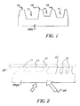
- a flexographic plate (FP) 5 is pressed directly onto printed media, such as, for example, paper, packaging material and the like (not shown)
- areas 10 that transfer ink to the printed media need to be elevated from blank areas 11 which do not transfer ink.
- the required depth of the blank areas 11 is such that when the FP 5 is pressed against another surface, the blank areas 11 should be kept out of contact with the surface.
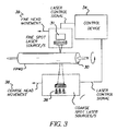
- FP 24 is being pressed firmly against contact surface 23 by pressure 20. Because FP 24 is deformable, imaging features 21 separated by large blank area 25 (typically used to produce large solid areas in imaging) will be deformed more strongly and pushed closer to contact surface 23 than imaging features 22 that are separated by small blank area 26 (typically used to produce fine detail areas in imaging). Therefore, large blank area 25 must maintain greater depth than small area 26 to prevent contact with the contact surface 23. Therefore, it follows that small blank area 26 may be engraved by the radiation system to a shallower depth than that required for large blank area 25. The HOHS takes advantage of the fact that large solid areas need to be processed to a depth which is greater than that required for fine detail.
- the HOHS may be configured with at least two groups of radiation sources, the groups comprising at least one radiation source, wherein the radiation sources within the groups emit radiation having the same intensity and spot size, different from the intensity and spot size of radiation sources in other groups, wherein the groups of radiation sources are operating simultaneously.
- Radiation sources include, but are not limited to, lasers, laser diodes, multi emitter laser diodes, laser bars, laser stacks, fiber lasers and the like.
- a lower power fine laser source may assist in processing solid areas; however, a high power broad laser source may only operate in areas that are greater than or equal to its spot size.
- the laser sources, fine and broad may be integrated into a single optical head, or separated into their own separate mounted heads. In each configuration, the laser sources are controlled and driven independently of each other.
- the HOHS may, for example, utilize one of the following sources:
- a fine laser source may comprise diode lasers having a single emitter, such as, for example:
- Both fine and broad source lasers are available in a fiber-coupled and non-fiber-coupled configurations.
- the laser is coupled to a fiber using a separate focusing lens or a lens defined by processing the fiber end to a surface capable of refracting the light into the fiber.
- the size of the aperture emerging from the fiber is determined by the radial dimension of the fiber. Since the light that is output from the aperture diverges, it needs to be imaged by using a lens, or system of lenses, to result in the desired spot size.
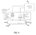
- Figure 3 illustrates one embodiment of a HOHS where fine laser source 31 and broad laser source 36 are mounted on carriages 39 and 38, respectively, which move along the longitudinal axis of a rotating drum 30 on which FP 40 is mounted.
- Laser sources 31 and 36 are controlled by control device 34 and carriages 39 and 38 may be placed independently of each other, at different locations with respect to the rotating drum 30.
- FP 40 is attached to drum 30 and then spun. While spinning, control device 34 directs laser source 36 to ablate certain large areas that are greater than or equal to the spot size of the laser source 36; while laser source 31 is directed to ablate certain small areas, areas requiring fine detail and large areas where laser source 31 is directed to operate. Laser sources 31 and 36 are moved on their respective carriage 39 and 38, respectively, so as to locate the laser sources 31 and 36 in the area where they need to operate.
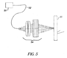
- Figure 4 illustrates another embodiment of the HOHS where fine laser source 42 and broad laser source 43 are mounted on the same carriage 41. Lasers 42 and 43 are controlled independently by controller device 44, according to the data containing details of the image, for engraving on FP 46 mounted on drum 45.
- FP 46 is attached to drum 45 and then spun. While spinning, control device 44 directs laser 43 to ablate certain large areas that are greater than or equal to the spot size of the laser 43; while laser 42 is directed to ablate certain small areas, areas requiring fine detail and large areas where laser 42 is directed to operate. Laser sources 42 and 43 are moved on carriage 41 so as to locate the lasers 42 and 43 in the area where they need to operate.
- Figure 5 illustrates a fiber coupled diode laser 50 coupled to fiber 52, fiber 52 coupled to imaging optical system 54 which achieves a spot of desired dimension to focus and engrave on the engraved media 55.
- the fiber 52 in this embodiment may be a single mode laser source, multimode fiber or bundle of fibers for a multimode laser source.
- Figure 6 describes another embodiment wherein a multiplicity of fiber coupled diode lasers 63 are used.
- the fibers 60 are arranged in an array and can be imaged by a lens or system of lenses 61 on the engraved media 62.
- the system of lenses 61 may be configured as a telecentric lens.
- the diode laser 63 or multiplicity of diode lasers 63 may be other than fiber coupled diodes.
- the beam emitted from a diode laser spreads out as it leaves its front facet and needs to be captured by a lens positioned in close proximity to the emitter. Very often the light leaves the lens collimated, namely, propagating along the optical axis with minimum divergence.
- the collimating lens may include a single lens element or several elements. In case the laser diode 63 is other than fiber coupled, additional elements are required for producing circular beam profile.
- Figure 7 depicts laser beam 75 emitted from diode laser 71 and collimated with collimating lens 70.
- a subsequent optical system 73 may be placed in the path of beam 72 to image the beam on engraved media 74.
- the optical system 73 may also include elements for shaping the laser beam 72 that emerges from the collimating lens as a circle.
- the laser beam 75 emerging from a laser diode has an elliptical cross section by nature.
- Figure 8 shows non-fiber coupled diode optics 80, including diode laser 84, collimating lens 81 and imaging lens 82 for imaging on engraved media 83.
- Figure 9 shows one or more diode lasers 90 formed in a well-defined array.
- light from each diode 90 is captured by a respective collimating lens 91.
- Light from the array of collimated lenses 91 is captured into the imaging lens system 92 and then imaged on the engraved media 93.
- a broad laser source can be constructed from fiber coupled or non-fiber coupled semiconductor laser bars or stacks such as available for example from: http://www.dilas.de/products/products.html, as well as from: http://www.scd.co.il/lapid.asp
- a laser bar emits light from a relatively large area, the width of which is typically 10 or 12 mm, and consists of an array of sub emitters.
- the total output power of a bar reaches 50 Watts or more.
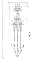
- Figure 10 describes a laser bar 100 with multiple emitters.
- the optical system consists of a lens 101 that collimates the fast axis of the angular span of 65 degrees, and an additional lens 102 that collimates the slow axis, it contains cylindrical elements in front of each individual emitter.
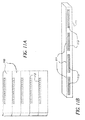
- Figure 11A shows several bars 110 that are coupled vertically and Figure 11B shows several bars 111 that are coupled horizontally.
- Each bar 110 and 111 is configured with an array of emitters 112 and 113, respectively.
- the output power generated by bars 110 is the sum of the output powers generated by all individual bars.
- the bars 110 and 111 may be individually addressable.
- Optical elements such as polarization and/or wavelength dependent beam combiners can be further used to combine the light from several such laser devices in order to increase the brightness of the broad laser source.
- the light emitted from these bars can be coupled by utilizing various micro-optical elements into fibers or a bundle of fibers.
- the fiber coupled or non-fiber coupled source is then imaged to a desired spot size, which is broad relative to the fine spot. This laser spot is then used to ablate the coarse structure of the flexographic printing plate to the required relief.
- the laser beam 124 is a collimated laser beam from laser source 120 coupled to collimating lens 122.
- the beam enters to polarizing beam combiner (PBC) 128.
- PBC polarizing beam combiner
- the orientation of the PBC and laser source 120 is such that the output from PBC is at right angles to its original direction.
- the beam 125 from laser source 121 coupled to collimating lens 123 is similar to laser beam 124.
- the beam 125 enters polarization half wavelength retarding waveplate 126.
- the emerging beam 127 has its state of polarization rotated by 90 degrees.
- beam 127 is transmitted and combines with beam 124 to form the combined output beam 129.
- the light sources may be tailored to the special optical and thermal characteristics of a direct engraving printing plate, such as the printing plate described in co-owned U.S. Patent Application No. 11/353,217 .
Landscapes
- Engineering & Computer Science (AREA)
- Physics & Mathematics (AREA)
- Optics & Photonics (AREA)
- Plasma & Fusion (AREA)
- Manufacturing & Machinery (AREA)
- Mechanical Engineering (AREA)
- Manufacture Or Reproduction Of Printing Formes (AREA)
- Laser Beam Processing (AREA)
- Exposure And Positioning Against Photoresist Photosensitive Materials (AREA)
- Printing Plates And Materials Therefor (AREA)
- Polishing Bodies And Polishing Tools (AREA)
Applications Claiming Priority (2)
| Application Number | Priority Date | Filing Date | Title |
|---|---|---|---|
| US11/615,025 US7827912B2 (en) | 2006-12-22 | 2006-12-22 | Hybrid optical head for direct engraving of flexographic printing plates |
| PCT/US2007/025055 WO2008088504A1 (en) | 2006-12-22 | 2007-12-07 | Direct engraving of flexographic printing plates |
Publications (2)
| Publication Number | Publication Date |
|---|---|
| EP2097260A1 EP2097260A1 (en) | 2009-09-09 |
| EP2097260B1 true EP2097260B1 (en) | 2010-07-21 |
Family
ID=39267791
Family Applications (1)
| Application Number | Title | Priority Date | Filing Date |
|---|---|---|---|
| EP07862617A Not-in-force EP2097260B1 (en) | 2006-12-22 | 2007-12-07 | Direct engraving of flexographic printing plates |
Country Status (8)
| Country | Link |
|---|---|
| US (1) | US7827912B2 (enExample) |
| EP (1) | EP2097260B1 (enExample) |
| JP (1) | JP2010513095A (enExample) |
| KR (1) | KR20090094102A (enExample) |
| CN (1) | CN101568432B (enExample) |
| AT (1) | ATE474718T1 (enExample) |
| DE (1) | DE602007007984D1 (enExample) |
| WO (1) | WO2008088504A1 (enExample) |
Families Citing this family (31)
| Publication number | Priority date | Publication date | Assignee | Title |
|---|---|---|---|---|
| US20080018943A1 (en) * | 2006-06-19 | 2008-01-24 | Eastman Kodak Company | Direct engraving of flexographic printing plates |
| US8621996B2 (en) | 2007-08-27 | 2014-01-07 | Eastman Kodak Company | Engraving of printing plates |
| US8418612B2 (en) | 2008-03-07 | 2013-04-16 | Fujifilm Corporation | Printing plate making apparatus and printing plate making method |
| US20110014573A1 (en) * | 2009-07-14 | 2011-01-20 | Eynat Matzner | System for engraving flexographic plates |
| US8284229B2 (en) * | 2009-09-08 | 2012-10-09 | Eastman Kodak Company | Imaging head for 3D imaging |
| JP5500716B2 (ja) * | 2010-02-17 | 2014-05-21 | 富士フイルム株式会社 | レリーフ製造装置およびレリーフ製造方法 |
| US20110236705A1 (en) * | 2010-03-29 | 2011-09-29 | Ophira Melamed | Flexographic printing precursors and methods of making |
| US8154808B2 (en) * | 2010-05-11 | 2012-04-10 | Eastman Kodak Company | Autofocus imaging apparatus |
| US20110278268A1 (en) * | 2010-05-13 | 2011-11-17 | Alon Siman-Tov | Writing an image on flexographic media |
| US20110277648A1 (en) * | 2010-05-13 | 2011-11-17 | Alon Siman-Tov | Imaging apparatus for flexographic printing |
| US20110278767A1 (en) | 2010-05-17 | 2011-11-17 | David Aviel | Direct engraving of flexographic printing plates |
| US8365662B2 (en) * | 2010-05-17 | 2013-02-05 | Eastman Kodak Company | Direct engraving of flexographic printing plates |
| US20120240802A1 (en) | 2011-03-22 | 2012-09-27 | Landry-Coltrain Christine J | Laser-engraveable flexographic printing precursors |
| US9156299B2 (en) | 2011-06-30 | 2015-10-13 | Eastman Kodak Company | Laser-imageable flexographic printing precursors and methods of imaging |
| US8603725B2 (en) | 2011-07-28 | 2013-12-10 | Eastman Kodak Company | Laser-engraveable compositions and flexographic printing precursors |
| US8613999B2 (en) | 2011-07-28 | 2013-12-24 | Eastman Kodak Company | Laser-engraveable compositions and flexographic printing precursors comprising organic porous particles |
| CN103732408A (zh) * | 2011-08-09 | 2014-04-16 | 伊斯曼柯达公司 | 胶印成像系统 |
| US20130036929A1 (en) * | 2011-08-09 | 2013-02-14 | Moshe Nakash | Method for offset media system |
| US20130101834A1 (en) | 2011-10-20 | 2013-04-25 | Dana Barshishat | Laser-imageable flexographic printing precursors and methods of imaging |
| US9156241B2 (en) | 2011-12-12 | 2015-10-13 | Eastman Kodak Company | Laser-imageable flexographic printing precursors and methods of relief imaging |
| US9266316B2 (en) | 2012-01-18 | 2016-02-23 | Eastman Kodak Company | Dual-layer laser-imageable flexographic printing precursors |
| US20130288006A1 (en) | 2012-04-26 | 2013-10-31 | Anna C. Greene | Laser-engraveable elements and method of use |
| US9522523B2 (en) | 2012-04-30 | 2016-12-20 | Eastman Kodak Company | Laser-imageable flexographic printing precursors and methods of imaging |
| EP2778784B8 (en) | 2013-03-11 | 2022-02-23 | Esko-Graphics Imaging GmbH | Apparatus and method for multi-beam direct engraving of elastomeric printing plates and sleeves |
| WO2015053757A1 (en) | 2013-10-09 | 2015-04-16 | Eastman Kodak Company | Direct laser-engraveable patternable elements and uses |
| CN104191091B (zh) * | 2014-08-27 | 2015-11-11 | 武汉凌云光电科技有限责任公司 | 柔性电路板堆栈式激光焊接装置及方法 |
| US20190101526A1 (en) | 2016-03-30 | 2019-04-04 | Sony Corporation | Blood state analysis apparatus, blood state analysis system, blood state analysis method, and program |
| EP3558646B1 (en) | 2016-12-20 | 2021-02-17 | Agfa Nv | Flexo-platemaker and method of making a flexo-plate |
| CN109109457B (zh) * | 2018-08-03 | 2022-05-24 | 常州龙润激光科技有限公司 | 一种网纹辊及其制造方法 |
| NL2024368B1 (en) | 2019-12-03 | 2021-08-31 | Xeikon Prepress Nv | Method and system for processing a raster image file |
| CN115356900A (zh) * | 2022-09-05 | 2022-11-18 | 安徽国芯光刻技术有限公司 | 一种多波长激光混波照明光路结构 |
Family Cites Families (20)
| Publication number | Priority date | Publication date | Assignee | Title |
|---|---|---|---|---|
| US5370961A (en) | 1992-12-02 | 1994-12-06 | Eastman Kodak Company | Method of electrostatic transferring very small dry toner particles using an intermediate |
| US5635086A (en) * | 1995-10-10 | 1997-06-03 | The Esab Group, Inc. | Laser-plasma arc metal cutting apparatus |
| DE19544502C1 (de) | 1995-11-29 | 1997-05-15 | Baasel Scheel Lasergraphics Gm | Lasergravuranlage |
| US5968656A (en) | 1997-04-25 | 1999-10-19 | Eastman Kodak Company | Electrostatographic intermediate transfer member having a ceramer-containing surface layer |
| DE19840926B4 (de) * | 1998-09-08 | 2013-07-11 | Hell Gravure Systems Gmbh & Co. Kg | Anordnung zur Materialbearbeitung mittels Laserstrahlen und deren Verwendung |
| US6421522B2 (en) | 2000-05-17 | 2002-07-16 | Nexpress Solutions Llc | Method and apparatus for setting registration in a multicolor printing machine based on a change in toner profile |
| DE50113773D1 (de) | 2000-05-17 | 2008-05-08 | Eastman Kodak Co | Verfahren zur Einstellung des Registers bei einer Mehrfarbendruckmaschine |
| DE10024456A1 (de) | 2000-05-18 | 2001-11-29 | Heidelberger Druckmasch Ag | Integrierte Laser- und UV-Belichtung von Druckplatten |
| DE10105979A1 (de) | 2001-02-09 | 2002-08-14 | Heidelberger Druckmasch Ag | Verfahren und Vorrichtung zur Materialbearbeitung durch Lasergravur |
| FR2820681B1 (fr) * | 2001-02-14 | 2003-05-16 | Sagadev | Dispositif de fabrication d'un cliche d'impression pour l'imprimerie |
| ATE282526T1 (de) | 2001-05-25 | 2004-12-15 | Stork Prints Austria Gmbh | Verfahren und vorrichtung zur herstellung einer druckform |
| FR2834802B1 (fr) * | 2002-01-11 | 2004-06-04 | Macdermid Graphic Arts Sa | Procede de fabrication d'une plaque de flexographie et plaque de flexographie obtenue par ce procede |
| US7126619B2 (en) * | 2002-05-31 | 2006-10-24 | Buzz Sales Company, Inc. | System and method for direct laser engraving of images onto a printing substrate |
| JP4220271B2 (ja) * | 2003-02-28 | 2009-02-04 | 旭化成ケミカルズ株式会社 | レーザー彫刻可能なシームレス印刷原版およびその成形方法 |
| JP4654592B2 (ja) | 2004-04-02 | 2011-03-23 | 味の素株式会社 | 代謝フラックスの決定方法 |
| EP1593493A1 (de) * | 2004-05-05 | 2005-11-09 | Hell Gravure Systems GmbH | Vorrichtung zur Gravur von Näpfchen in Druckzylindern mittels Laserlichts |
| DE602005011543D1 (de) | 2004-09-30 | 2009-01-22 | Dainippon Screen Mfg | Verfahren zur Herstellung einer Druckplatte und Druckplattenherstellungsgerät |
| US7167630B2 (en) * | 2004-11-08 | 2007-01-23 | Kodak Il, Ltd. | Beam shaper and imaging head having beam shapers |
| US7265772B2 (en) | 2004-12-16 | 2007-09-04 | Esko Graphics A/S | Beam illumination system and method for producing printing plates |
| JP4703222B2 (ja) | 2005-03-08 | 2011-06-15 | 大日本スクリーン製造株式会社 | 印刷版の製版装置 |
-
2006
- 2006-12-22 US US11/615,025 patent/US7827912B2/en active Active
-
2007
- 2007-12-07 EP EP07862617A patent/EP2097260B1/en not_active Not-in-force
- 2007-12-07 KR KR1020097012975A patent/KR20090094102A/ko not_active Withdrawn
- 2007-12-07 DE DE602007007984T patent/DE602007007984D1/de active Active
- 2007-12-07 AT AT07862617T patent/ATE474718T1/de not_active IP Right Cessation
- 2007-12-07 CN CN200780047852.4A patent/CN101568432B/zh not_active Expired - Fee Related
- 2007-12-07 JP JP2009542794A patent/JP2010513095A/ja active Pending
- 2007-12-07 WO PCT/US2007/025055 patent/WO2008088504A1/en not_active Ceased
Also Published As
| Publication number | Publication date |
|---|---|
| WO2008088504A1 (en) | 2008-07-24 |
| DE602007007984D1 (de) | 2010-09-02 |
| CN101568432B (zh) | 2014-12-31 |
| CN101568432A (zh) | 2009-10-28 |
| US7827912B2 (en) | 2010-11-09 |
| US20080153038A1 (en) | 2008-06-26 |
| ATE474718T1 (de) | 2010-08-15 |
| EP2097260A1 (en) | 2009-09-09 |
| JP2010513095A (ja) | 2010-04-30 |
| KR20090094102A (ko) | 2009-09-03 |
Similar Documents
| Publication | Publication Date | Title |
|---|---|---|
| EP2097260B1 (en) | Direct engraving of flexographic printing plates | |
| EP2029361B1 (en) | Direct engraving of flexographic printing plates | |
| US5463200A (en) | Marking of a workpiece by light energy | |
| US20060255023A1 (en) | Processing spot defined by a plurality of laser beams | |
| US20090168111A9 (en) | Printing form processing with fine and coarse engraving tool processing tracks | |
| US7885012B2 (en) | Shearing radiation beam for imaging printing media | |
| JP2008272830A (ja) | レーザ加工装置 | |
| EP2170607B1 (en) | Registering printing sleeve segments | |
| US20110241257A1 (en) | Multi-beam exposure scanning method and apparatus, and method for manufacturing printing plate | |
| US6822669B2 (en) | Method and multibeam scanning device for the ablation of flexo printing plates by laser engraving | |
| US6768505B2 (en) | Method and apparatus for exposing printing forms | |
| US8969757B2 (en) | Relief manufacturing apparatus and relief manufacturing method | |
| JP2003088966A5 (ja) | レーザマーキング装置,及び2次元コード印字方法 | |
| US20020135745A1 (en) | Multibeam scanning device for scanning a photosensitive material with a multi-spot array, and method of correcting the position of image points of the multi-spot array | |
| JP2003080388A (ja) | レーザ加工装置 | |
| US20100282720A1 (en) | Exposure device and engraving apparatus | |
| US20060279793A1 (en) | Printing form processing with a plurality of engraving tool tracks forming lines | |
| JP3530769B2 (ja) | 照明装置及びそれを用いた光加工機 | |
| JPH10305551A (ja) | 製版装置 | |
| KR20250141719A (ko) | 레이저 라이터 및 레이저 라이터 동작 방법 | |
| JP5220793B2 (ja) | マルチビーム露光走査方法及び装置並びに印刷版の製造方法 | |
| CN114012274A (zh) | 激光雕刻装置及系统 | |
| JP2000033704A (ja) | インクジェットプリンタ装置のノズル穴加工装置及びそのノズル穴加工方法 |
Legal Events
| Date | Code | Title | Description |
|---|---|---|---|
| PUAI | Public reference made under article 153(3) epc to a published international application that has entered the european phase |
Free format text: ORIGINAL CODE: 0009012 |
|
| 17P | Request for examination filed |
Effective date: 20090626 |
|
| AK | Designated contracting states |
Kind code of ref document: A1 Designated state(s): AT BE BG CH CY CZ DE DK EE ES FI FR GB GR HU IE IS IT LI LT LU LV MC MT NL PL PT RO SE SI SK TR |
|
| RIN1 | Information on inventor provided before grant (corrected) |
Inventor name: CHAYET, HAIM Inventor name: SIMAN-TOV, ALON |
|
| 17Q | First examination report despatched |
Effective date: 20091021 |
|
| GRAP | Despatch of communication of intention to grant a patent |
Free format text: ORIGINAL CODE: EPIDOSNIGR1 |
|
| DAX | Request for extension of the european patent (deleted) | ||
| GRAS | Grant fee paid |
Free format text: ORIGINAL CODE: EPIDOSNIGR3 |
|
| GRAA | (expected) grant |
Free format text: ORIGINAL CODE: 0009210 |
|
| AK | Designated contracting states |
Kind code of ref document: B1 Designated state(s): AT BE BG CH CY CZ DE DK EE ES FI FR GB GR HU IE IS IT LI LT LU LV MC MT NL PL PT RO SE SI SK TR |
|
| REG | Reference to a national code |
Ref country code: GB Ref legal event code: FG4D |
|
| REG | Reference to a national code |
Ref country code: CH Ref legal event code: EP |
|
| REG | Reference to a national code |
Ref country code: IE Ref legal event code: FG4D |
|
| REF | Corresponds to: |
Ref document number: 602007007984 Country of ref document: DE Date of ref document: 20100902 Kind code of ref document: P |
|
| REG | Reference to a national code |
Ref country code: NL Ref legal event code: VDEP Effective date: 20100721 |
|
| LTIE | Lt: invalidation of european patent or patent extension |
Effective date: 20100721 |
|
| PG25 | Lapsed in a contracting state [announced via postgrant information from national office to epo] |
Ref country code: FI Free format text: LAPSE BECAUSE OF FAILURE TO SUBMIT A TRANSLATION OF THE DESCRIPTION OR TO PAY THE FEE WITHIN THE PRESCRIBED TIME-LIMIT Effective date: 20100721 Ref country code: AT Free format text: LAPSE BECAUSE OF FAILURE TO SUBMIT A TRANSLATION OF THE DESCRIPTION OR TO PAY THE FEE WITHIN THE PRESCRIBED TIME-LIMIT Effective date: 20100721 Ref country code: LT Free format text: LAPSE BECAUSE OF FAILURE TO SUBMIT A TRANSLATION OF THE DESCRIPTION OR TO PAY THE FEE WITHIN THE PRESCRIBED TIME-LIMIT Effective date: 20100721 Ref country code: NL Free format text: LAPSE BECAUSE OF FAILURE TO SUBMIT A TRANSLATION OF THE DESCRIPTION OR TO PAY THE FEE WITHIN THE PRESCRIBED TIME-LIMIT Effective date: 20100721 |
|
| PG25 | Lapsed in a contracting state [announced via postgrant information from national office to epo] |
Ref country code: PL Free format text: LAPSE BECAUSE OF FAILURE TO SUBMIT A TRANSLATION OF THE DESCRIPTION OR TO PAY THE FEE WITHIN THE PRESCRIBED TIME-LIMIT Effective date: 20100721 Ref country code: CY Free format text: LAPSE BECAUSE OF FAILURE TO SUBMIT A TRANSLATION OF THE DESCRIPTION OR TO PAY THE FEE WITHIN THE PRESCRIBED TIME-LIMIT Effective date: 20100721 Ref country code: SI Free format text: LAPSE BECAUSE OF FAILURE TO SUBMIT A TRANSLATION OF THE DESCRIPTION OR TO PAY THE FEE WITHIN THE PRESCRIBED TIME-LIMIT Effective date: 20100721 Ref country code: IS Free format text: LAPSE BECAUSE OF FAILURE TO SUBMIT A TRANSLATION OF THE DESCRIPTION OR TO PAY THE FEE WITHIN THE PRESCRIBED TIME-LIMIT Effective date: 20101121 Ref country code: PT Free format text: LAPSE BECAUSE OF FAILURE TO SUBMIT A TRANSLATION OF THE DESCRIPTION OR TO PAY THE FEE WITHIN THE PRESCRIBED TIME-LIMIT Effective date: 20101122 Ref country code: BG Free format text: LAPSE BECAUSE OF FAILURE TO SUBMIT A TRANSLATION OF THE DESCRIPTION OR TO PAY THE FEE WITHIN THE PRESCRIBED TIME-LIMIT Effective date: 20101021 |
|
| PG25 | Lapsed in a contracting state [announced via postgrant information from national office to epo] |
Ref country code: LV Free format text: LAPSE BECAUSE OF FAILURE TO SUBMIT A TRANSLATION OF THE DESCRIPTION OR TO PAY THE FEE WITHIN THE PRESCRIBED TIME-LIMIT Effective date: 20100721 Ref country code: SE Free format text: LAPSE BECAUSE OF FAILURE TO SUBMIT A TRANSLATION OF THE DESCRIPTION OR TO PAY THE FEE WITHIN THE PRESCRIBED TIME-LIMIT Effective date: 20100721 Ref country code: GR Free format text: LAPSE BECAUSE OF FAILURE TO SUBMIT A TRANSLATION OF THE DESCRIPTION OR TO PAY THE FEE WITHIN THE PRESCRIBED TIME-LIMIT Effective date: 20101022 |
|
| PG25 | Lapsed in a contracting state [announced via postgrant information from national office to epo] |
Ref country code: DK Free format text: LAPSE BECAUSE OF FAILURE TO SUBMIT A TRANSLATION OF THE DESCRIPTION OR TO PAY THE FEE WITHIN THE PRESCRIBED TIME-LIMIT Effective date: 20100721 |
|
| PLBE | No opposition filed within time limit |
Free format text: ORIGINAL CODE: 0009261 |
|
| STAA | Information on the status of an ep patent application or granted ep patent |
Free format text: STATUS: NO OPPOSITION FILED WITHIN TIME LIMIT |
|
| PG25 | Lapsed in a contracting state [announced via postgrant information from national office to epo] |
Ref country code: EE Free format text: LAPSE BECAUSE OF FAILURE TO SUBMIT A TRANSLATION OF THE DESCRIPTION OR TO PAY THE FEE WITHIN THE PRESCRIBED TIME-LIMIT Effective date: 20100721 Ref country code: CZ Free format text: LAPSE BECAUSE OF FAILURE TO SUBMIT A TRANSLATION OF THE DESCRIPTION OR TO PAY THE FEE WITHIN THE PRESCRIBED TIME-LIMIT Effective date: 20100721 Ref country code: SK Free format text: LAPSE BECAUSE OF FAILURE TO SUBMIT A TRANSLATION OF THE DESCRIPTION OR TO PAY THE FEE WITHIN THE PRESCRIBED TIME-LIMIT Effective date: 20100721 Ref country code: RO Free format text: LAPSE BECAUSE OF FAILURE TO SUBMIT A TRANSLATION OF THE DESCRIPTION OR TO PAY THE FEE WITHIN THE PRESCRIBED TIME-LIMIT Effective date: 20100721 |
|
| 26N | No opposition filed |
Effective date: 20110426 |
|
| PG25 | Lapsed in a contracting state [announced via postgrant information from national office to epo] |
Ref country code: ES Free format text: LAPSE BECAUSE OF FAILURE TO SUBMIT A TRANSLATION OF THE DESCRIPTION OR TO PAY THE FEE WITHIN THE PRESCRIBED TIME-LIMIT Effective date: 20101101 |
|
| PG25 | Lapsed in a contracting state [announced via postgrant information from national office to epo] |
Ref country code: MC Free format text: LAPSE BECAUSE OF NON-PAYMENT OF DUE FEES Effective date: 20101231 |
|
| REG | Reference to a national code |
Ref country code: DE Ref legal event code: R097 Ref document number: 602007007984 Country of ref document: DE Effective date: 20110426 |
|
| PG25 | Lapsed in a contracting state [announced via postgrant information from national office to epo] |
Ref country code: IE Free format text: LAPSE BECAUSE OF NON-PAYMENT OF DUE FEES Effective date: 20101207 |
|
| PG25 | Lapsed in a contracting state [announced via postgrant information from national office to epo] |
Ref country code: MT Free format text: LAPSE BECAUSE OF FAILURE TO SUBMIT A TRANSLATION OF THE DESCRIPTION OR TO PAY THE FEE WITHIN THE PRESCRIBED TIME-LIMIT Effective date: 20100721 Ref country code: IT Free format text: LAPSE BECAUSE OF NON-PAYMENT OF DUE FEES Effective date: 20101207 |
|
| PGFP | Annual fee paid to national office [announced via postgrant information from national office to epo] |
Ref country code: IT Payment date: 20101231 Year of fee payment: 4 |
|
| PGFP | Annual fee paid to national office [announced via postgrant information from national office to epo] |
Ref country code: BE Payment date: 20120103 Year of fee payment: 5 |
|
| REG | Reference to a national code |
Ref country code: CH Ref legal event code: PL |
|
| PG25 | Lapsed in a contracting state [announced via postgrant information from national office to epo] |
Ref country code: HU Free format text: LAPSE BECAUSE OF FAILURE TO SUBMIT A TRANSLATION OF THE DESCRIPTION OR TO PAY THE FEE WITHIN THE PRESCRIBED TIME-LIMIT Effective date: 20110122 Ref country code: LU Free format text: LAPSE BECAUSE OF NON-PAYMENT OF DUE FEES Effective date: 20101207 |
|
| PG25 | Lapsed in a contracting state [announced via postgrant information from national office to epo] |
Ref country code: LI Free format text: LAPSE BECAUSE OF NON-PAYMENT OF DUE FEES Effective date: 20111231 Ref country code: TR Free format text: LAPSE BECAUSE OF FAILURE TO SUBMIT A TRANSLATION OF THE DESCRIPTION OR TO PAY THE FEE WITHIN THE PRESCRIBED TIME-LIMIT Effective date: 20100721 Ref country code: CH Free format text: LAPSE BECAUSE OF NON-PAYMENT OF DUE FEES Effective date: 20111231 |
|
| BERE | Be: lapsed |
Owner name: EASTMAN KODAK CY Effective date: 20121231 |
|
| PG25 | Lapsed in a contracting state [announced via postgrant information from national office to epo] |
Ref country code: BE Free format text: LAPSE BECAUSE OF NON-PAYMENT OF DUE FEES Effective date: 20121231 |
|
| PG25 | Lapsed in a contracting state [announced via postgrant information from national office to epo] |
Ref country code: IT Free format text: LAPSE BECAUSE OF NON-PAYMENT OF DUE FEES Effective date: 20121207 |
|
| PGFP | Annual fee paid to national office [announced via postgrant information from national office to epo] |
Ref country code: GB Payment date: 20131126 Year of fee payment: 7 |
|
| PGFP | Annual fee paid to national office [announced via postgrant information from national office to epo] |
Ref country code: FR Payment date: 20131126 Year of fee payment: 7 |
|
| GBPC | Gb: european patent ceased through non-payment of renewal fee |
Effective date: 20141207 |
|
| REG | Reference to a national code |
Ref country code: FR Ref legal event code: ST Effective date: 20150831 |
|
| PG25 | Lapsed in a contracting state [announced via postgrant information from national office to epo] |
Ref country code: GB Free format text: LAPSE BECAUSE OF NON-PAYMENT OF DUE FEES Effective date: 20141207 |
|
| PG25 | Lapsed in a contracting state [announced via postgrant information from national office to epo] |
Ref country code: FR Free format text: LAPSE BECAUSE OF NON-PAYMENT OF DUE FEES Effective date: 20141231 |
|
| REG | Reference to a national code |
Ref country code: DE Ref legal event code: R082 Ref document number: 602007007984 Country of ref document: DE Representative=s name: PATENTANWALTSKANZLEI LIERMANN-CASTELL, DE Ref country code: DE Ref legal event code: R081 Ref document number: 602007007984 Country of ref document: DE Owner name: MIRACLON CORP., WILMINGTON, US Free format text: FORMER OWNER: EASTMAN KODAK CO., ROCHESTER, N.Y., US Ref country code: DE Ref legal event code: R081 Ref document number: 602007007984 Country of ref document: DE Owner name: MIRACLON CORP., OAKDALE, US Free format text: FORMER OWNER: EASTMAN KODAK CO., ROCHESTER, N.Y., US |
|
| REG | Reference to a national code |
Ref country code: DE Ref legal event code: R082 Ref document number: 602007007984 Country of ref document: DE Representative=s name: PATENTANWALTSKANZLEI LIERMANN-CASTELL, DE Ref country code: DE Ref legal event code: R081 Ref document number: 602007007984 Country of ref document: DE Owner name: MIRACLON CORP., OAKDALE, US Free format text: FORMER OWNER: MIRACLON CORP., WILMINGTON, DELAWARE, US |
|
| PGFP | Annual fee paid to national office [announced via postgrant information from national office to epo] |
Ref country code: DE Payment date: 20201217 Year of fee payment: 14 |
|
| REG | Reference to a national code |
Ref country code: DE Ref legal event code: R119 Ref document number: 602007007984 Country of ref document: DE |
|
| PG25 | Lapsed in a contracting state [announced via postgrant information from national office to epo] |
Ref country code: DE Free format text: LAPSE BECAUSE OF NON-PAYMENT OF DUE FEES Effective date: 20220701 |