EP2097186B1 - Apparatus and method for controlled cooling - Google Patents
Apparatus and method for controlled cooling Download PDFInfo
- Publication number
- EP2097186B1 EP2097186B1 EP07846662A EP07846662A EP2097186B1 EP 2097186 B1 EP2097186 B1 EP 2097186B1 EP 07846662 A EP07846662 A EP 07846662A EP 07846662 A EP07846662 A EP 07846662A EP 2097186 B1 EP2097186 B1 EP 2097186B1
- Authority
- EP
- European Patent Office
- Prior art keywords
- header
- valve
- cooling fluid
- control method
- air
- Prior art date
- Legal status (The legal status is an assumption and is not a legal conclusion. Google has not performed a legal analysis and makes no representation as to the accuracy of the status listed.)
- Not-in-force
Links
- 238000001816 cooling Methods 0.000 title claims abstract description 20
- 238000000034 method Methods 0.000 title claims abstract description 18
- 239000012809 cooling fluid Substances 0.000 claims abstract description 34
- 239000002184 metal Substances 0.000 claims abstract description 5
- 229910052751 metal Inorganic materials 0.000 claims abstract description 5
- 239000012530 fluid Substances 0.000 claims description 6
- 229910000831 Steel Inorganic materials 0.000 claims description 5
- 239000010959 steel Substances 0.000 claims description 5
- 150000002739 metals Chemical class 0.000 claims description 3
- XLYOFNOQVPJJNP-UHFFFAOYSA-N water Substances O XLYOFNOQVPJJNP-UHFFFAOYSA-N 0.000 description 20
- 239000002826 coolant Substances 0.000 description 4
- 238000001514 detection method Methods 0.000 description 1
- 238000005259 measurement Methods 0.000 description 1
- 239000000203 mixture Substances 0.000 description 1
- 238000010791 quenching Methods 0.000 description 1
- 230000000171 quenching effect Effects 0.000 description 1
Images
Classifications
-
- B—PERFORMING OPERATIONS; TRANSPORTING
- B21—MECHANICAL METAL-WORKING WITHOUT ESSENTIALLY REMOVING MATERIAL; PUNCHING METAL
- B21B—ROLLING OF METAL
- B21B45/00—Devices for surface or other treatment of work, specially combined with or arranged in, or specially adapted for use in connection with, metal-rolling mills
- B21B45/02—Devices for surface or other treatment of work, specially combined with or arranged in, or specially adapted for use in connection with, metal-rolling mills for lubricating, cooling, or cleaning
-
- B—PERFORMING OPERATIONS; TRANSPORTING
- B21—MECHANICAL METAL-WORKING WITHOUT ESSENTIALLY REMOVING MATERIAL; PUNCHING METAL
- B21B—ROLLING OF METAL
- B21B45/00—Devices for surface or other treatment of work, specially combined with or arranged in, or specially adapted for use in connection with, metal-rolling mills
- B21B45/02—Devices for surface or other treatment of work, specially combined with or arranged in, or specially adapted for use in connection with, metal-rolling mills for lubricating, cooling, or cleaning
- B21B45/0203—Cooling
- B21B45/0209—Cooling devices, e.g. using gaseous coolants
- B21B45/0215—Cooling devices, e.g. using gaseous coolants using liquid coolants, e.g. for sections, for tubes
- B21B45/0233—Spray nozzles, Nozzle headers; Spray systems
-
- B—PERFORMING OPERATIONS; TRANSPORTING
- B21—MECHANICAL METAL-WORKING WITHOUT ESSENTIALLY REMOVING MATERIAL; PUNCHING METAL
- B21B—ROLLING OF METAL
- B21B45/00—Devices for surface or other treatment of work, specially combined with or arranged in, or specially adapted for use in connection with, metal-rolling mills
- B21B45/02—Devices for surface or other treatment of work, specially combined with or arranged in, or specially adapted for use in connection with, metal-rolling mills for lubricating, cooling, or cleaning
- B21B45/0203—Cooling
- B21B45/0209—Cooling devices, e.g. using gaseous coolants
- B21B45/0215—Cooling devices, e.g. using gaseous coolants using liquid coolants, e.g. for sections, for tubes
- B21B45/0218—Cooling devices, e.g. using gaseous coolants using liquid coolants, e.g. for sections, for tubes for strips, sheets, or plates
Definitions
- the invention relates to the general field of controlled cooling of hot plate or strip shaped metal and specifically to the accelerated cooling and direct quenching of steel strips and plates.
- the controlled cooling of hot rolled steel is very important for achieving the desired microstructure and properties.
- Modern plate and hot strip mills generally use powerful cooling systems for this purpose whereby the accurate control of the temperature and the cooling rate are very important.
- Water is often used as a cooling fluid.
- U-tube type laminar cooling header There are many different designs of cooling system available from the prior art.
- One of the most common types is the U-tube type laminar cooling header.
- the main water supply is via a large diameter pipe and the water flows out of a plurality of U-tubes and down onto the product which is being cooled.
- the reason that U-tubes are used is so that the main supply pipe stays full of water even when the flow is switched off. This means that the time delay between switching on the flow and water coming out of the U-tubes is minimized. It also means that when the flow is switched off only a small quantity of water drips out of the U-tubes.
- U-tube type headers there are a number of limitations with U-tube type headers. In practice it is found that U-tubes only give a sharply defined flow pattern over a limited range of flows. The ratio between the minimum and maximum flows which give a good flow pattern is typically about 3:1. Another limitation is that the jets are a large distance above the product which is being cooled which reduces the cooling efficiency.
- a main water supply pipe feeds water into a header. Inside the header are a large number of nozzles which produce a large number of water jets.
- the large numbers of jets provide much greater cooling power than U-tube type headers.
- the design allows the jets to be much closer to the product being cooled and this further increases the cooling power.
- the large numbers of small jets also allow a much wider range of stable flows to be used. The ratio between the minimum and maximum stable flows is 20:1 or more compared to around 3:1 for U-tubes.
- the multi-jet type header offers many advantages over the U-tube type headers it does have some disadvantages.
- the flow is switched off the water in the supply pipe drains out through the nozzles. This is undesirable because the water could drip onto products that do not require any further cooling. It also means that when the flow is switched on for the next product that does require cooling the supply pipe has to be re-filled before the flow is properly established.
- Another undesirable feature is that at low flows it takes a long time to change the flow.
- the reason for this is that the flow out of the nozzles is proportional to the square-root of the pressure at the nozzles.
- the pressure in the header is typically about 4 bar or roughly 40 meters head of water. With a 20:1 ratio between minimum and maximum flow, the pressure required for minimum flow is therefore only 40/(20 x 20) meters which is only 0.1 meters.
- the supply pipe is typically 300 mm in diameter this means that for minimum flow the supply pipe is only partially full. If the flow into the supply pipe is changed the flow out of the nozzles will not match the flow into the supply pipe until the water level in the pipe has reached the correct new equilibrium level. This can take up to 100 seconds or more at very low flows.
- Another objective of the present invention is to overcome the disadvantages of the multi-jet type cooling header by making it possible to change the flow quickly even at low flow rates. Another objective of the invention is to enable the correct flow to be established more quickly and to stop the dripping of the water when the flow is switched off.
- the objective is solved by the invention comprising the apparatus according to claim 1 and the control method according to claim 9.
- a first valve is arranged so as to allow air to escape from the header when the header is being filled with the cooling fluid and to prevent air from getting back into the header.
- the first valve is installed so that it connects to the highest part of the header with a connecting pipe.
- the first valve allows air to escape from the header and prevents cooling fluid from escaping from the header when being filled with the cooling fluid.
- the apparatus according to the invention allows a quick switching on and off. It can be assured that the header is fully filled and when working at lower flow rates stable operation can be assured.
- the first valve is a float type valve. This valve allows air out of the header but prevents the cooling fluid from escaping when the header is full.
- a second valve is connected to the first valve.
- the second valve prevents air from going back into the header.
- the second valve is a non-return valve. This avoids the ingress of air into the header when the pressure in the header drops.
- the first valve is an electrically operated valve which is operated so as to allow air out of the header when the header is being filled and to prevent air from getting back into the header when the header is full. Due to this operation mode a fully automated control is possible.
- Another suitable embodiment is achieved when the second valve is an electrically operated valve. This allows an improved control of the header.
- an electrically operated solenoid valve is arranged in the connecting pipe between the first and the second valve, which allows air back into the header for draining of the header. This additional valve assures quick drain of the header when required.
- the advantageous embodiment of the inventive apparatus can be extended by a drain valve, which is attached to the header, in particular to the nozzle carrier and which allows even quicker drain of the cooling fluid from the header. This is of relevance whenever uncontrolled dripping from the header or the nozzles has to be avoided.
- the header is completely filled with water and air is prevented from entering into the header during operation by means of a first valve. Due to the controlled filling and control of the air getting back into the header or being allowed to escape the flow conditions can be controlled to a much greater extent.
- a preferred embodiment of the inventive control method is characterized in that the first valve is operated so as to allow air out of the header when the header is being filled and to prevent air from getting back into the header when the header is full.
- Another preferred embodiment of the inventive control method is characterized in that a measured pressure in the header is used as an input value for the control of the first valve.
- the pressure allows an improved detection of the current filling level in the header.
- Other measurements e.g. the filling level in the header could be use as well.
- the flow rate of the fluid supplied from a fluid supply is increased. This assures a completely filled header and a quick filling allowing a quick response when the header has to be put in operating conditions. Further more the increased flow rate assures that air is completely removed from the header.
- the header remains fully filled during operation.
- This special condition allows a stable operation of the header even when the flow rate of the cooling fluid at the nozzles is reduced to low values. Further more changes to the flow rate into the header cause the flow rate out of the nozzles to change immediately because the header remains full all the time and the height of water in the header and supply pipe does not have to change in order to change the pressure at the nozzles.
- a partial vacuum is created in the header such that the fluid pressure at the nozzles is smaller than the pressure due to the height of water in the header.
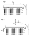
- Fig. 1 shows a header 1 with a supply pipe 2 and a plurality of nozzles 3 arranged in a nozzle carrier 4.
- the cooling medium enters the header at 5. From the main supply pipe 2 the cooling medium then flows into the nozzle carrier 4 and out through the nozzles 3. Cooling medium jets 6 are created by the nozzles 3. Water is often used as the cooling medium however according to the invention other media or mixtures of media might be used.
- a float type valve 7 is connected to the highest point of the header 1 which in this embodiment is the top of the supply pipe 2. The float type valve 7 allows air to escape from the header 1 when the cooling fluid is switched on but it does not allow cooling fluid to escape. Once the header 1 and supply pipe 2 are full of cooling fluid the float rises and seals off the outlet.
- a header according to the prior art if the flow into the header at 5 is reduced so that the head of cooling fluid required to produce this flow out of nozzles 3 is less than the height of the top of the supply pipe 2 above the nozzles then the float type valve 7 will allow air back into the header 1 and the cooling fluid level in the supply pipe 2 will drop until the flow out of the nozzles matches the flow into the header. Due to the large volume of the header it can take up to 100 seconds or even longer before the height of water in the header stabilises and the flow out 6 of the nozzles 3 is equal to the flow into the header 5.
- the header according to the invention overcomes such problems.
- Fig. 2 shows the header according to the invention with the addition of a non-return valve 8 which is connected to the float valve 7. This non-return valve prevents air from getting back into the system.
- the combination of the float type valve 7 and the non-return valve 8 improves the operation of the system considerably. Because the header is full of water even at low flows then changes to the flow into the header 5 cause an immediate change in the flow out of the nozzles 3.
- the cooling fluid flow 5 can be reduced to the required level.
- the non-return valve 8 prevents air from getting back into the header 1 so the cooling fluid level cannot drop and the system stays full of cooling fluid. If the required flow is low then a partial vacuum is created in the upper part of the supply pipe 2 so that the pressure of cooling fluid at the nozzles 3 reaches the correct equilibrium pressure where the flow out of the nozzles 3 matches the flow into the header 1. The flow out of the nozzles 3 responds almost instantaneously to changes in the flow going into the header 1 because the system stays full of cooling fluid and all that changes is the pressure in the header 1.
- an electrically operated solenoid valve 9 can be opened to allow air back into the header 1 to let the cooling fluid drain out through the nozzles 3.
- An additional valve 10 can be added to provide faster draining if required.
- the exemplary embodiment using a float type valve 7 and non-return valve 8 is a simple method of achieving the desired objectives but that these same objectives could be achieved by other embodiments such as electrically operated valves.
- the principal of the invention is that the header 1 is completely filled with cooling fluid and air is prevented from entering even when the pressure required to produce the desired flow is less than the height of the system above the nozzles 3 and a partial vacuum is created to achieve this.
Landscapes
- Engineering & Computer Science (AREA)
- Mechanical Engineering (AREA)
- Heat Treatments In General, Especially Conveying And Cooling (AREA)
- Devices That Are Associated With Refrigeration Equipment (AREA)
- Heat Treatment Of Strip Materials And Filament Materials (AREA)
- Superconductors And Manufacturing Methods Therefor (AREA)
Abstract
Description
- The invention relates to the general field of controlled cooling of hot plate or strip shaped metal and specifically to the accelerated cooling and direct quenching of steel strips and plates.
- The controlled cooling of hot rolled steel is very important for achieving the desired microstructure and properties. Modern plate and hot strip mills generally use powerful cooling systems for this purpose whereby the accurate control of the temperature and the cooling rate are very important. Water is often used as a cooling fluid.
- There are many different designs of cooling system available from the prior art. One of the most common types is the U-tube type laminar cooling header. The main water supply is via a large diameter pipe and the water flows out of a plurality of U-tubes and down onto the product which is being cooled. The reason that U-tubes are used is so that the main supply pipe stays full of water even when the flow is switched off. This means that the time delay between switching on the flow and water coming out of the U-tubes is minimized. It also means that when the flow is switched off only a small quantity of water drips out of the U-tubes.
- However there are a number of limitations with U-tube type headers. In practice it is found that U-tubes only give a sharply defined flow pattern over a limited range of flows. The ratio between the minimum and maximum flows which give a good flow pattern is typically about 3:1. Another limitation is that the jets are a large distance above the product which is being cooled which reduces the cooling efficiency.
- Due to the limitations of conventional U-tube designs, many modem systems use multi-jet type headers instead. Some of these designs are described in
EP 0 176 494 ,EP 0 178 281 ,EP 0 233 854 andEP 0 297 077 . A main water supply pipe feeds water into a header. Inside the header are a large number of nozzles which produce a large number of water jets. There are a number of advantages to this type of multi-jet header design. The large numbers of jets provide much greater cooling power than U-tube type headers. In addition the design allows the jets to be much closer to the product being cooled and this further increases the cooling power. The large numbers of small jets also allow a much wider range of stable flows to be used. The ratio between the minimum and maximum stable flows is 20:1 or more compared to around 3:1 for U-tubes. - Whilst the multi-jet type header offers many advantages over the U-tube type headers it does have some disadvantages. When the flow is switched off the water in the supply pipe drains out through the nozzles. This is undesirable because the water could drip onto products that do not require any further cooling. It also means that when the flow is switched on for the next product that does require cooling the supply pipe has to be re-filled before the flow is properly established.
- Another undesirable feature is that at low flows it takes a long time to change the flow. The reason for this is that the flow out of the nozzles is proportional to the square-root of the pressure at the nozzles. At maximum flow the pressure in the header is typically about 4 bar or roughly 40 meters head of water. With a 20:1 ratio between minimum and maximum flow, the pressure required for minimum flow is therefore only 40/(20 x 20) meters which is only 0.1 meters. Since the supply pipe is typically 300 mm in diameter this means that for minimum flow the supply pipe is only partially full. If the flow into the supply pipe is changed the flow out of the nozzles will not match the flow into the supply pipe until the water level in the pipe has reached the correct new equilibrium level. This can take up to 100 seconds or more at very low flows.
- It is therefore an objective of the present invention to overcome the disadvantages of the multi-jet type cooling header by making it possible to change the flow quickly even at low flow rates. Another objective of the invention is to enable the correct flow to be established more quickly and to stop the dripping of the water when the flow is switched off.
- The objective is solved by the invention comprising the apparatus according to
claim 1 and the control method according toclaim 9. - According to the present inventive apparatus a first valve is arranged so as to allow air to escape from the header when the header is being filled with the cooling fluid and to prevent air from getting back into the header. The first valve is installed so that it connects to the highest part of the header with a connecting pipe. The first valve allows air to escape from the header and prevents cooling fluid from escaping from the header when being filled with the cooling fluid. The apparatus according to the invention allows a quick switching on and off. It can be assured that the header is fully filled and when working at lower flow rates stable operation can be assured. According to a special embodiment of the inventive apparatus the first valve is a float type valve. This valve allows air out of the header but prevents the cooling fluid from escaping when the header is full.
- According to a special embodiment of the inventive apparatus a second valve is connected to the first valve. The second valve prevents air from going back into the header.
- According to a further special embodiment of the inventive apparatus the second valve is a non-return valve. This avoids the ingress of air into the header when the pressure in the header drops.
- According to a suitable embodiment of the inventive apparatus the first valve is an electrically operated valve which is operated so as to allow air out of the header when the header is being filled and to prevent air from getting back into the header when the header is full. Due to this operation mode a fully automated control is possible.
- Another suitable embodiment is achieved when the second valve is an electrically operated valve. This allows an improved control of the header.
- In an advantageous embodiment of the inventive apparatus an electrically operated solenoid valve is arranged in the connecting pipe between the first and the second valve, which allows air back into the header for draining of the header. This additional valve assures quick drain of the header when required.
- Furthermore the advantageous embodiment of the inventive apparatus can be extended by a drain valve, which is attached to the header, in particular to the nozzle carrier and which allows even quicker drain of the cooling fluid from the header. This is of relevance whenever uncontrolled dripping from the header or the nozzles has to be avoided.
- According to the inventive control method for the operation of an apparatus for the controlled cooling of hot plate or strip shaped metals, in particular steel, by means of a cooling fluid, with a header, comprising a central supply pipe and a plurality of nozzles arranged in a nozzle carrier, the header is completely filled with water and air is prevented from entering into the header during operation by means of a first valve. Due to the controlled filling and control of the air getting back into the header or being allowed to escape the flow conditions can be controlled to a much greater extent.
- A preferred embodiment of the inventive control method is characterized in that the first valve is operated so as to allow air out of the header when the header is being filled and to prevent air from getting back into the header when the header is full.
- Another preferred embodiment of the inventive control method is characterized in that a measured pressure in the header is used as an input value for the control of the first valve. The pressure allows an improved detection of the current filling level in the header. Other measurements e.g. the filling level in the header could be use as well.
- According to a special embodiment of the inventive control method during filling of the header the flow rate of the fluid supplied from a fluid supply is increased. This assures a completely filled header and a quick filling allowing a quick response when the header has to be put in operating conditions. Further more the increased flow rate assures that air is completely removed from the header.
- According to a special embodiment of the inventive control method the header remains fully filled during operation. This special condition allows a stable operation of the header even when the flow rate of the cooling fluid at the nozzles is reduced to low values. Further more changes to the flow rate into the header cause the flow rate out of the nozzles to change immediately because the header remains full all the time and the height of water in the header and supply pipe does not have to change in order to change the pressure at the nozzles.
- According to a preferred embodiment of the inventive control method a partial vacuum is created in the header such that the fluid pressure at the nozzles is smaller than the pressure due to the height of water in the header. The method assures that no air can ingress the header even at low flow rates of the cooling fluid. As a consequence the flow rate can be reduced to a much lower value than with conventional headers as no air can get into the header. Thus even at low flow rates the system and the flow of cooling fluid remains stable.
- The invention is described in more detail in the following figures presenting possible embodiments of the present invention without limiting the invention to the presented embodiments.
-
Fig 1 : Sectional view of a header according to prior art -
Fig. 2 : Sectional view of a header according to the invention. -
Fig. 1 shows aheader 1 with asupply pipe 2 and a plurality ofnozzles 3 arranged in a nozzle carrier 4. The cooling medium enters the header at 5. From themain supply pipe 2 the cooling medium then flows into the nozzle carrier 4 and out through thenozzles 3. Coolingmedium jets 6 are created by thenozzles 3. Water is often used as the cooling medium however according to the invention other media or mixtures of media might be used. A float type valve 7 is connected to the highest point of theheader 1 which in this embodiment is the top of thesupply pipe 2. The float type valve 7 allows air to escape from theheader 1 when the cooling fluid is switched on but it does not allow cooling fluid to escape. Once theheader 1 andsupply pipe 2 are full of cooling fluid the float rises and seals off the outlet. - In a header according to the prior art if the flow into the header at 5 is reduced so that the head of cooling fluid required to produce this flow out of
nozzles 3 is less than the height of the top of thesupply pipe 2 above the nozzles then the float type valve 7 will allow air back into theheader 1 and the cooling fluid level in thesupply pipe 2 will drop until the flow out of the nozzles matches the flow into the header. Due to the large volume of the header it can take up to 100 seconds or even longer before the height of water in the header stabilises and the flow out 6 of thenozzles 3 is equal to the flow into theheader 5. The header according to the invention overcomes such problems. -
Fig. 2 shows the header according to the invention with the addition of a non-return valve 8 which is connected to the float valve 7. This non-return valve prevents air from getting back into the system. - The combination of the float type valve 7 and the non-return valve 8 improves the operation of the system considerably. Because the header is full of water even at low flows then changes to the flow into the
header 5 cause an immediate change in the flow out of thenozzles 3. - In addition the draining of the
header 1 when the flow is switched off is much reduced. This means that there is less cooling fluid dripping out of theheader 1 when it is not in operation and that when flow is required it switches on almost instantaneously because theheader 1 is already full. - To further improve the operation of the system a particular control method is required in combination with the float type valve 7 and the non-return valve 8. When the cooling
fluid flow 5 is first switched on a large flow is used to ensure that theheader 1 is completely full. To make sure that the system is completely full of cooling fluid this flow must be large enough that the head of cooling fluid required to produce this flow through thenozzles 3 is greater than the height of the non-return valve 7 above thenozzles 3. The larger the flow that is used during this pre-filling step the quicker theheader 1 will fill up. - Once the
header 1 is full the coolingfluid flow 5 can be reduced to the required level. The non-return valve 8 prevents air from getting back into theheader 1 so the cooling fluid level cannot drop and the system stays full of cooling fluid. If the required flow is low then a partial vacuum is created in the upper part of thesupply pipe 2 so that the pressure of cooling fluid at thenozzles 3 reaches the correct equilibrium pressure where the flow out of thenozzles 3 matches the flow into theheader 1. The flow out of thenozzles 3 responds almost instantaneously to changes in the flow going into theheader 1 because the system stays full of cooling fluid and all that changes is the pressure in theheader 1. - If the apparatus for the controlled cooling is not going to be in operation for some time or it is necessary to stop any cooling fluid from dripping out of the
header 1 it may be desirable to allow the cooling fluid to drain out of theheader 1. In this case an electrically operatedsolenoid valve 9 can be opened to allow air back into theheader 1 to let the cooling fluid drain out through thenozzles 3. Anadditional valve 10 can be added to provide faster draining if required. - It will be apparent that the exemplary embodiment using a float type valve 7 and non-return valve 8 is a simple method of achieving the desired objectives but that these same objectives could be achieved by other embodiments such as electrically operated valves. The principal of the invention is that the
header 1 is completely filled with cooling fluid and air is prevented from entering even when the pressure required to produce the desired flow is less than the height of the system above thenozzles 3 and a partial vacuum is created to achieve this.
Claims (14)
- An apparatus for the controlled cooling of hot plate or strip shaped metals, in particular steel, by means of a cooling fluid, with a header (1), comprising a central supply pipe (2) and a plurality of nozzles (3) arranged in a nozzle carrier (4), characterized in that at least a first valve (7) is connected by a conduit to the header such that the valve (7) allows air to escape from the header when the header is being filled with the cooling fluid and prevents air from getting back into the header.
- Apparatus as defined in claim 1, characterized in that the first valve (7) is a float type valve.
- Apparatus as defined in claim 1 or 2, characterized in that a second valve (8) is connected to the first valve (7).
- Apparatus as defined in claim 3, characterized in that the second valve (8) is a non-return valve.
- Apparatus as defined in claim 1 or 2, characterized in that the first valve (7) is an electrically operated valve which is operated so as to allow air out of the header when the header is being filled and to prevent air from getting back into the header when the header is full.
- Apparatus as defined in claim 3 - 5, characterized in that the second valve (8) is an electrically operated valve.
- Apparatus as defined in claims 3 - 6, characterized in that a solenoid valve (9) is arranged in the connecting pipe between the first (7) and the second valve (8), which allows air back into the header for draining of the header (1).
- Apparatus as defined in claims 1 - 7, characterized in that a drain valve (10) is attached to the header (1), in particular to the nozzle carrier (4) which allows quick drain of the cooling fluid from the header (1).
- Control method for the operation of an apparatus according to any one of claims 1 to 8 for the controlled cooling of hot plate or strip shaped metals, in particular steel, by means of a cooling fluid, with a header (1), comprising a central supply pipe (2) and a plurality of nozzles (3) arranged in a nozzle carrier (4) characterized in that during filling the header (1) is completely filled with cooling fluid and during operation air is prevented from entering into the header (1) by means of a first valve (7).
- Control method as defined in claim 9, characterized in that the first valve (7) is operated so as to allow air out of the header when the header is being filled and to prevent air from getting back into the header when the header is full.
- Control method as defined in claim 10, characterized in that a measured pressure in the header (1) is used as an input value for the control of the first valve (7).
- Control method as defined in claim 9-11, characterized in that during filling of the header (1) the flow rate of the fluid supplied from a fluid supply (5) is increased.
- Control method as defined in claim 9 - 12, characterized in that the header (1) remains fully filled during operation.
- Control method as defined in claims 9-13, characterized in that a partial vacuum is created in the header (1), when the fluid pressure above the nozzles (3) is smaller than the pressure required for a desired flow rate.
Priority Applications (3)
| Application Number | Priority Date | Filing Date | Title |
|---|---|---|---|
| EP07846662A EP2097186B1 (en) | 2006-12-27 | 2007-11-19 | Apparatus and method for controlled cooling |
| PL07846662T PL2097186T3 (en) | 2006-12-27 | 2007-11-19 | Apparatus and method for controlled cooling |
| SI200730749T SI2097186T1 (en) | 2006-12-27 | 2007-11-19 | Apparatus and method for controlled cooling |
Applications Claiming Priority (3)
| Application Number | Priority Date | Filing Date | Title |
|---|---|---|---|
| EP06256592A EP1938911A1 (en) | 2006-12-27 | 2006-12-27 | Apparatus and method for controlled cooling |
| EP07846662A EP2097186B1 (en) | 2006-12-27 | 2007-11-19 | Apparatus and method for controlled cooling |
| PCT/EP2007/009983 WO2008077449A1 (en) | 2006-12-27 | 2007-11-19 | Apparatus and method for controlled cooling |
Publications (2)
| Publication Number | Publication Date |
|---|---|
| EP2097186A1 EP2097186A1 (en) | 2009-09-09 |
| EP2097186B1 true EP2097186B1 (en) | 2011-07-20 |
Family
ID=37951947
Family Applications (2)
| Application Number | Title | Priority Date | Filing Date |
|---|---|---|---|
| EP06256592A Withdrawn EP1938911A1 (en) | 2006-12-27 | 2006-12-27 | Apparatus and method for controlled cooling |
| EP07846662A Not-in-force EP2097186B1 (en) | 2006-12-27 | 2007-11-19 | Apparatus and method for controlled cooling |
Family Applications Before (1)
| Application Number | Title | Priority Date | Filing Date |
|---|---|---|---|
| EP06256592A Withdrawn EP1938911A1 (en) | 2006-12-27 | 2006-12-27 | Apparatus and method for controlled cooling |
Country Status (13)
| Country | Link |
|---|---|
| US (1) | US9358597B2 (en) |
| EP (2) | EP1938911A1 (en) |
| JP (2) | JP2010514567A (en) |
| KR (1) | KR101279932B1 (en) |
| CN (1) | CN101616755B (en) |
| AT (1) | ATE516899T1 (en) |
| BR (1) | BRPI0720655A2 (en) |
| DK (1) | DK2097186T3 (en) |
| ES (1) | ES2367456T3 (en) |
| PL (1) | PL2097186T3 (en) |
| RU (1) | RU2466811C2 (en) |
| SI (1) | SI2097186T1 (en) |
| WO (1) | WO2008077449A1 (en) |
Families Citing this family (17)
| Publication number | Priority date | Publication date | Assignee | Title |
|---|---|---|---|---|
| US9526933B2 (en) * | 2008-09-15 | 2016-12-27 | Engineered Corrosion Solutions, Llc | High nitrogen and other inert gas anti-corrosion protection in wet pipe fire protection system |
| KR101160034B1 (en) | 2009-07-24 | 2012-06-26 | 현대제철 주식회사 | apparatus for prevention of scale and removing it in cooling water pipe of hot rolling process |
| EP2767352A1 (en) * | 2013-02-14 | 2014-08-20 | Siemens VAI Metals Technologies GmbH | Cooling of a metal strip with position-regulated valve device |
| EP2767353A1 (en) * | 2013-02-15 | 2014-08-20 | Siemens VAI Metals Technologies GmbH | Cooling section with power cooling and laminar cooling |
| EP2777836A1 (en) * | 2013-03-14 | 2014-09-17 | Siemens VAI Metals Technologies GmbH | Cooling device with spray bar with elongated outlets |
| RU2549811C1 (en) * | 2013-10-29 | 2015-04-27 | Федеральное государственное бюджетное образовательное учреждение высшего профессионального образования Юго-Западный государственный университет | Device for cooling control of item during rolling |
| CN105921535B (en) * | 2016-07-12 | 2017-09-15 | 北京科技大学 | A kind of Strip control cooling super-intensive cooler |
| CN110267748B (en) * | 2017-03-31 | 2021-04-13 | 日本制铁株式会社 | Cooling device for hot-rolled steel sheet and cooling method for hot-rolled steel sheet |
| EP3395463B2 (en) * | 2017-04-26 | 2024-10-30 | Primetals Technologies Austria GmbH | Cooling of a product which is to be rolled |
| DE102017122495A1 (en) | 2017-09-27 | 2019-03-28 | Dürr Systems Ag | Applicator with a small nozzle spacing |
| DE102017122493A1 (en) | 2017-09-27 | 2019-03-28 | Dürr Systems Ag | Applicator with small nozzle spacing |
| RU2744838C1 (en) * | 2017-12-20 | 2021-03-16 | Даниэли & К. Оффичине Мекканике С.П.А. | Installation for heat treatment of metal products |
| EP3623068B1 (en) * | 2018-09-12 | 2021-07-14 | Primetals Technologies Germany GmbH | Application devices for cooling lines with second connection |
| EP3670682A1 (en) * | 2018-12-20 | 2020-06-24 | Primetals Technologies Austria GmbH | Production of a metal strip with an austenite-martensite compound structure |
| DE102019206596A1 (en) * | 2019-03-06 | 2020-09-10 | Sms Group Gmbh | Device for cooling a strip-shaped product and method for operating such a device |
| CN113441557A (en) * | 2021-06-30 | 2021-09-28 | 莱芜钢铁集团银山型钢有限公司 | MULPIC cooling emergency device, control method and control system |
| CN115716090B (en) * | 2021-08-27 | 2026-01-20 | 宝山钢铁股份有限公司 | Hot rolling laminar cooling method |
Family Cites Families (27)
| Publication number | Priority date | Publication date | Assignee | Title |
|---|---|---|---|---|
| US2627868A (en) * | 1950-09-07 | 1953-02-10 | Clarence H Runnels | Hydraulic vent valve |
| US3315611A (en) * | 1965-06-28 | 1967-04-25 | Thompson Tank And Mfg Co Inc | Portable vacuum and pressure liquid tank truck |
| US3490482A (en) * | 1968-04-25 | 1970-01-20 | Elihu L Sachs | Liquid transfer system |
| US3841559A (en) * | 1973-10-18 | 1974-10-15 | Exotech | Apparatus for forming high pressure pulsed jets of liquid |
| JPS584756U (en) * | 1981-07-02 | 1983-01-12 | トヨタ自動車株式会社 | Air suction end control valve |
| JPS5950911A (en) * | 1982-09-17 | 1984-03-24 | Nippon Steel Corp | Cooler for steel plate in hot strip mill |
| JPS5994708A (en) | 1982-11-22 | 1984-05-31 | Tokyo Optical Co Ltd | Zoom lens moving device |
| JPS5994708U (en) * | 1982-12-14 | 1984-06-27 | 石川島播磨重工業株式会社 | Cooling equipment for high temperature steel materials |
| EP0176494A1 (en) | 1984-09-25 | 1986-04-02 | CENTRE DE RECHERCHES METALLURGIQUES CENTRUM VOOR RESEARCH IN DE METALLURGIE Association sans but lucratif | Method for cooling a moving metallic product |
| BE900784A (en) * | 1984-10-09 | 1985-04-09 | Centre Rech Metallurgique | DEVICE FOR COOLING A MOVING METAL PRODUCT AND INSTALLATION COMPRISING THE APPLICATION. |
| BE904177A (en) | 1986-02-05 | 1986-08-05 | Centre Rech Metallurgique | DEVICE FOR COOLING A MOVING METAL PRODUCT. |
| JPH0816246B2 (en) * | 1986-08-28 | 1996-02-21 | 新日本製鐵株式会社 | Spray cooling device for heat treatment furnace |
| BE1000674A6 (en) | 1987-06-26 | 1989-03-07 | Centre Rech Metallurgique | Device for cooling a metal product in motion. |
| JP2627868B2 (en) | 1994-05-18 | 1997-07-09 | 太平洋工業株式会社 | Motorized valve |
| JPH09294943A (en) | 1996-03-06 | 1997-11-18 | Sumitomo Metal Ind Ltd | Lower tank cooling device in gas-liquid spraying device and vacuum degassing device |
| JPH10235425A (en) * | 1997-02-26 | 1998-09-08 | Nkk Corp | High temperature steel plate cooling system |
| JPH10296320A (en) * | 1997-04-23 | 1998-11-10 | Nkk Corp | Steel plate cooling device |
| NL1010222C2 (en) * | 1998-09-30 | 2000-03-31 | Spiro Research Bv | Method for operating a closed hot water installation and equipment to be used therewith. |
| AUPQ099199A0 (en) * | 1999-06-17 | 1999-07-08 | Herlihy, Geoffrey Francis | An improved air release valve |
| US6247487B1 (en) * | 1999-10-27 | 2001-06-19 | Ford Global Tech., Inc. | Valve assembly |
| DE10025639A1 (en) | 2000-05-24 | 2001-11-29 | Sms Demag Ag | Nozzle bar for cooling or descaling metal billets, especially rolled stock |
| CN1304133C (en) * | 2002-08-08 | 2007-03-14 | 杰富意钢铁株式会社 | Cooling device, manufacturing method, and manufacturing line for hot rolled steel band |
| KR100642656B1 (en) * | 2002-08-08 | 2006-11-03 | 제이에프이 스틸 가부시키가이샤 | Cooling device of hot rolled steel strip, manufacturing method of hot rolled steel sheet and manufacturing line of hot rolled steel sheet |
| JP2004313933A (en) | 2003-04-16 | 2004-11-11 | Sankureo:Kk | Spraying washing machine |
| JP2005315116A (en) * | 2004-04-27 | 2005-11-10 | Toyota Motor Corp | Air vent structure for coolant flow path |
| US7571866B2 (en) * | 2004-10-29 | 2009-08-11 | Rnj Enterprises, Llc | High-pressure gas powered full body self misting device |
| US7481238B2 (en) * | 2005-08-09 | 2009-01-27 | Roger Ramoth | Automatic degassing valve |
-
2006
- 2006-12-27 EP EP06256592A patent/EP1938911A1/en not_active Withdrawn
-
2007
- 2007-11-19 WO PCT/EP2007/009983 patent/WO2008077449A1/en not_active Ceased
- 2007-11-19 DK DK07846662.0T patent/DK2097186T3/en active
- 2007-11-19 BR BRPI0720655-0A2A patent/BRPI0720655A2/en not_active IP Right Cessation
- 2007-11-19 RU RU2009128691/02A patent/RU2466811C2/en not_active IP Right Cessation
- 2007-11-19 JP JP2009543350A patent/JP2010514567A/en active Pending
- 2007-11-19 KR KR1020097015781A patent/KR101279932B1/en not_active Expired - Fee Related
- 2007-11-19 CN CN2007800483081A patent/CN101616755B/en not_active Expired - Fee Related
- 2007-11-19 US US12/521,145 patent/US9358597B2/en not_active Expired - Fee Related
- 2007-11-19 EP EP07846662A patent/EP2097186B1/en not_active Not-in-force
- 2007-11-19 PL PL07846662T patent/PL2097186T3/en unknown
- 2007-11-19 AT AT07846662T patent/ATE516899T1/en active
- 2007-11-19 SI SI200730749T patent/SI2097186T1/en unknown
- 2007-11-19 ES ES07846662T patent/ES2367456T3/en active Active
-
2014
- 2014-01-24 JP JP2014011171A patent/JP5828009B2/en not_active Expired - Fee Related
Also Published As
| Publication number | Publication date |
|---|---|
| EP2097186A1 (en) | 2009-09-09 |
| KR101279932B1 (en) | 2013-07-05 |
| RU2466811C2 (en) | 2012-11-20 |
| JP2010514567A (en) | 2010-05-06 |
| WO2008077449A1 (en) | 2008-07-03 |
| DK2097186T3 (en) | 2011-10-31 |
| RU2009128691A (en) | 2011-02-10 |
| JP2014111281A (en) | 2014-06-19 |
| ATE516899T1 (en) | 2011-08-15 |
| JP5828009B2 (en) | 2015-12-02 |
| EP1938911A1 (en) | 2008-07-02 |
| PL2097186T3 (en) | 2011-12-30 |
| US9358597B2 (en) | 2016-06-07 |
| CN101616755A (en) | 2009-12-30 |
| ES2367456T3 (en) | 2011-11-03 |
| KR20090094470A (en) | 2009-09-07 |
| CN101616755B (en) | 2011-05-18 |
| WO2008077449A9 (en) | 2009-07-16 |
| BRPI0720655A2 (en) | 2014-01-28 |
| SI2097186T1 (en) | 2011-11-30 |
| US20100044024A1 (en) | 2010-02-25 |
Similar Documents
| Publication | Publication Date | Title |
|---|---|---|
| US9358597B2 (en) | Apparatus and method for controlled cooling | |
| DE102009051931A1 (en) | Method for early leak detection of cool water in a cooling device for cooling a continuous casting plant for the production of a cast metal strand, comprises detecting the pressure value of fluid by pressure sensor | |
| JP6359637B2 (en) | Method and facility for supplying subcooled cryogenic liquid to at least one machining station | |
| JP2011516274A (en) | Method and apparatus for controlled cooling | |
| CN111471822A (en) | Control method of converter vaporization cooling system | |
| CN119187480A (en) | Closed-circuit water cooling system of ultra-thick plate blank continuous casting equipment and control method thereof | |
| JP4377873B2 (en) | Steel sheet controlled cooling device and cooling method | |
| CN117739593A (en) | Debugging method of negative pressure cooling system | |
| US5431213A (en) | Method for automated injection of gas into an installation for multiple strand casting of metals using the hot top process | |
| JPH0352593B2 (en) | ||
| KR100744033B1 (en) | Cooling Units and Cooling Methods | |
| CN223065267U (en) | A brewing water film method continuous deoxygenation monitoring device | |
| JP2011191194A (en) | Quality measuring instrument of water and steam quality monitoring device | |
| RU2351429C1 (en) | Refrigeration method of mold with receiving of sections and installation for its implementation | |
| KR101827809B1 (en) | Apparatus for supplying cooling water and method for controlling the same | |
| CN205448489U (en) | Array pipe type emulsifier cooling device | |
| KR20190073318A (en) | Apparatus for discharging a fixed quantity of fluid and method for the same | |
| CN116989499B (en) | Carbon dioxide cooling system for thermal spraying | |
| CN215373589U (en) | Multi-stage cooling device provided with bent flow guide pipe | |
| JP2020040009A (en) | Gas generator | |
| CN105728701A (en) | Water-cooling constant-temperature metal alloy casting die | |
| CN208817459U (en) | A kind of novel batch-type discharge oxygen-eliminating device | |
| KR100236169B1 (en) | Cooling control method of laminar flow cooling facilities | |
| JPS6384751A (en) | Method for detecting clogging of spray nozzle for continuous casting | |
| JP6123968B1 (en) | Power generation equipment |
Legal Events
| Date | Code | Title | Description |
|---|---|---|---|
| PUAI | Public reference made under article 153(3) epc to a published international application that has entered the european phase |
Free format text: ORIGINAL CODE: 0009012 |
|
| 17P | Request for examination filed |
Effective date: 20090608 |
|
| AK | Designated contracting states |
Kind code of ref document: A1 Designated state(s): AT BE BG CH CY CZ DE DK EE ES FI FR GB GR HU IE IS IT LI LT LU LV MC MT NL PL PT RO SE SI SK TR |
|
| DAX | Request for extension of the european patent (deleted) | ||
| RAP1 | Party data changed (applicant data changed or rights of an application transferred) |
Owner name: SIEMENS VAI METALS TECHNOLOGIES LTD. |
|
| GRAP | Despatch of communication of intention to grant a patent |
Free format text: ORIGINAL CODE: EPIDOSNIGR1 |
|
| GRAS | Grant fee paid |
Free format text: ORIGINAL CODE: EPIDOSNIGR3 |
|
| GRAA | (expected) grant |
Free format text: ORIGINAL CODE: 0009210 |
|
| AK | Designated contracting states |
Kind code of ref document: B1 Designated state(s): AT BE BG CH CY CZ DE DK EE ES FI FR GB GR HU IE IS IT LI LT LU LV MC MT NL PL PT RO SE SI SK TR |
|
| REG | Reference to a national code |
Ref country code: GB Ref legal event code: FG4D |
|
| REG | Reference to a national code |
Ref country code: CH Ref legal event code: EP |
|
| REG | Reference to a national code |
Ref country code: DE Ref legal event code: R096 Ref document number: 602007015974 Country of ref document: DE Effective date: 20110908 |
|
| REG | Reference to a national code |
Ref country code: RO Ref legal event code: EPE |
|
| REG | Reference to a national code |
Ref country code: DK Ref legal event code: T3 |
|
| REG | Reference to a national code |
Ref country code: SE Ref legal event code: TRGR |
|
| REG | Reference to a national code |
Ref country code: ES Ref legal event code: FG2A Ref document number: 2367456 Country of ref document: ES Kind code of ref document: T3 Effective date: 20111103 |
|
| REG | Reference to a national code |
Ref country code: NL Ref legal event code: VDEP Effective date: 20110720 |
|
| REG | Reference to a national code |
Ref country code: PL Ref legal event code: T3 |
|
| PG25 | Lapsed in a contracting state [announced via postgrant information from national office to epo] |
Ref country code: IS Free format text: LAPSE BECAUSE OF FAILURE TO SUBMIT A TRANSLATION OF THE DESCRIPTION OR TO PAY THE FEE WITHIN THE PRESCRIBED TIME-LIMIT Effective date: 20111120 Ref country code: LT Free format text: LAPSE BECAUSE OF FAILURE TO SUBMIT A TRANSLATION OF THE DESCRIPTION OR TO PAY THE FEE WITHIN THE PRESCRIBED TIME-LIMIT Effective date: 20110720 Ref country code: NL Free format text: LAPSE BECAUSE OF FAILURE TO SUBMIT A TRANSLATION OF THE DESCRIPTION OR TO PAY THE FEE WITHIN THE PRESCRIBED TIME-LIMIT Effective date: 20110720 Ref country code: PT Free format text: LAPSE BECAUSE OF FAILURE TO SUBMIT A TRANSLATION OF THE DESCRIPTION OR TO PAY THE FEE WITHIN THE PRESCRIBED TIME-LIMIT Effective date: 20111121 |
|
| PG25 | Lapsed in a contracting state [announced via postgrant information from national office to epo] |
Ref country code: CY Free format text: LAPSE BECAUSE OF FAILURE TO SUBMIT A TRANSLATION OF THE DESCRIPTION OR TO PAY THE FEE WITHIN THE PRESCRIBED TIME-LIMIT Effective date: 20110720 Ref country code: GR Free format text: LAPSE BECAUSE OF FAILURE TO SUBMIT A TRANSLATION OF THE DESCRIPTION OR TO PAY THE FEE WITHIN THE PRESCRIBED TIME-LIMIT Effective date: 20111021 Ref country code: LV Free format text: LAPSE BECAUSE OF FAILURE TO SUBMIT A TRANSLATION OF THE DESCRIPTION OR TO PAY THE FEE WITHIN THE PRESCRIBED TIME-LIMIT Effective date: 20110720 |
|
| PG25 | Lapsed in a contracting state [announced via postgrant information from national office to epo] |
Ref country code: SK Free format text: LAPSE BECAUSE OF FAILURE TO SUBMIT A TRANSLATION OF THE DESCRIPTION OR TO PAY THE FEE WITHIN THE PRESCRIBED TIME-LIMIT Effective date: 20110720 |
|
| PLBE | No opposition filed within time limit |
Free format text: ORIGINAL CODE: 0009261 |
|
| STAA | Information on the status of an ep patent application or granted ep patent |
Free format text: STATUS: NO OPPOSITION FILED WITHIN TIME LIMIT |
|
| REG | Reference to a national code |
Ref country code: HU Ref legal event code: AG4A Ref document number: E012783 Country of ref document: HU |
|
| PG25 | Lapsed in a contracting state [announced via postgrant information from national office to epo] |
Ref country code: EE Free format text: LAPSE BECAUSE OF FAILURE TO SUBMIT A TRANSLATION OF THE DESCRIPTION OR TO PAY THE FEE WITHIN THE PRESCRIBED TIME-LIMIT Effective date: 20110720 |
|
| 26N | No opposition filed |
Effective date: 20120423 |
|
| PG25 | Lapsed in a contracting state [announced via postgrant information from national office to epo] |
Ref country code: MC Free format text: LAPSE BECAUSE OF NON-PAYMENT OF DUE FEES Effective date: 20111130 |
|
| REG | Reference to a national code |
Ref country code: CH Ref legal event code: PL |
|
| PG25 | Lapsed in a contracting state [announced via postgrant information from national office to epo] |
Ref country code: LI Free format text: LAPSE BECAUSE OF NON-PAYMENT OF DUE FEES Effective date: 20111130 Ref country code: CH Free format text: LAPSE BECAUSE OF NON-PAYMENT OF DUE FEES Effective date: 20111130 |
|
| REG | Reference to a national code |
Ref country code: DE Ref legal event code: R097 Ref document number: 602007015974 Country of ref document: DE Effective date: 20120423 |
|
| REG | Reference to a national code |
Ref country code: IE Ref legal event code: MM4A |
|
| PG25 | Lapsed in a contracting state [announced via postgrant information from national office to epo] |
Ref country code: IE Free format text: LAPSE BECAUSE OF NON-PAYMENT OF DUE FEES Effective date: 20111119 |
|
| PG25 | Lapsed in a contracting state [announced via postgrant information from national office to epo] |
Ref country code: MT Free format text: LAPSE BECAUSE OF FAILURE TO SUBMIT A TRANSLATION OF THE DESCRIPTION OR TO PAY THE FEE WITHIN THE PRESCRIBED TIME-LIMIT Effective date: 20110720 |
|
| PG25 | Lapsed in a contracting state [announced via postgrant information from national office to epo] |
Ref country code: LU Free format text: LAPSE BECAUSE OF NON-PAYMENT OF DUE FEES Effective date: 20111119 |
|
| PG25 | Lapsed in a contracting state [announced via postgrant information from national office to epo] |
Ref country code: BG Free format text: LAPSE BECAUSE OF FAILURE TO SUBMIT A TRANSLATION OF THE DESCRIPTION OR TO PAY THE FEE WITHIN THE PRESCRIBED TIME-LIMIT Effective date: 20111020 |
|
| REG | Reference to a national code |
Ref country code: ES Ref legal event code: PC2A Owner name: SIEMENS PLC. Effective date: 20130702 |
|
| REG | Reference to a national code |
Ref country code: GB Ref legal event code: 732E Free format text: REGISTERED BETWEEN 20130627 AND 20130703 |
|
| REG | Reference to a national code |
Ref country code: FR Ref legal event code: TP Owner name: SIEMENS PLC, GB Effective date: 20130709 |
|
| REG | Reference to a national code |
Ref country code: SI Ref legal event code: SP73 Owner name: SIEMENS PLC.; GB Effective date: 20130723 |
|
| REG | Reference to a national code |
Ref country code: DE Ref legal event code: R082 Ref document number: 602007015974 Country of ref document: DE Representative=s name: MAIER, DANIEL OLIVER, DIPL.-ING. UNIV., DE |
|
| REG | Reference to a national code |
Ref country code: HU Ref legal event code: GB9C Owner name: SIEMENS PLC., GB Free format text: FORMER OWNER(S): SIEMENS VAI METALS TECHNOLOGIES LTD., GB Ref country code: HU Ref legal event code: FH1C Free format text: FORMER REPRESENTATIVE(S): DR. JAKAB JUDIT,SBGK SZABADALMI UEGYVIVOEI IRODA, HU Representative=s name: SBGK SZABADALMI UEGYVIVOEI IRODA, HU |
|
| REG | Reference to a national code |
Ref country code: DE Ref legal event code: R081 Ref document number: 602007015974 Country of ref document: DE Owner name: SIEMENS PLC., GB Free format text: FORMER OWNER: SIEMENS VAI METALS TECHNOLOGIES LTD., SHEFFIELD, GB Effective date: 20130925 Ref country code: DE Ref legal event code: R082 Ref document number: 602007015974 Country of ref document: DE Representative=s name: MAIER, DANIEL OLIVER, DIPL.-ING. UNIV., DE Effective date: 20130925 Ref country code: DE Ref legal event code: R081 Ref document number: 602007015974 Country of ref document: DE Owner name: SIEMENS PLC., FRIMLEY, GB Free format text: FORMER OWNER: SIEMENS VAI METALS TECHNOLOGIES LTD., SHEFFIELD, YORKSHIRE, GB Effective date: 20130925 Ref country code: DE Ref legal event code: R082 Ref document number: 602007015974 Country of ref document: DE Representative=s name: KINNSTAETTER, KLAUS, DIPL.-PHYS.UNIV., DE Effective date: 20130925 Ref country code: DE Ref legal event code: R081 Ref document number: 602007015974 Country of ref document: DE Owner name: PRIMETALS TECHNOLOGIES, LTD., GB Free format text: FORMER OWNER: SIEMENS VAI METALS TECHNOLOGIES LTD., SHEFFIELD, YORKSHIRE, GB Effective date: 20130925 |
|
| REG | Reference to a national code |
Ref country code: AT Ref legal event code: PC Ref document number: 516899 Country of ref document: AT Kind code of ref document: T Owner name: SIEMENS PLC, GB Effective date: 20150417 |
|
| REG | Reference to a national code |
Ref country code: GB Ref legal event code: 732E Free format text: REGISTERED BETWEEN 20150521 AND 20150527 |
|
| REG | Reference to a national code |
Ref country code: FR Ref legal event code: PLFP Year of fee payment: 9 |
|
| REG | Reference to a national code |
Ref country code: DE Ref legal event code: R082 Ref document number: 602007015974 Country of ref document: DE Representative=s name: KINNSTAETTER, KLAUS, DIPL.-PHYS.UNIV., DE |
|
| REG | Reference to a national code |
Ref country code: FR Ref legal event code: PLFP Year of fee payment: 10 |
|
| PGFP | Annual fee paid to national office [announced via postgrant information from national office to epo] |
Ref country code: GB Payment date: 20161122 Year of fee payment: 10 Ref country code: FI Payment date: 20161111 Year of fee payment: 10 Ref country code: DE Payment date: 20161121 Year of fee payment: 10 Ref country code: CZ Payment date: 20161116 Year of fee payment: 10 Ref country code: DK Payment date: 20161118 Year of fee payment: 10 Ref country code: FR Payment date: 20161118 Year of fee payment: 10 Ref country code: HU Payment date: 20161115 Year of fee payment: 10 |
|
| REG | Reference to a national code |
Ref country code: DE Ref legal event code: R082 Ref document number: 602007015974 Country of ref document: DE Representative=s name: KINNSTAETTER, KLAUS, DIPL.-PHYS.UNIV., DE Ref country code: DE Ref legal event code: R081 Ref document number: 602007015974 Country of ref document: DE Owner name: PRIMETALS TECHNOLOGIES, LTD., GB Free format text: FORMER OWNER: SIEMENS PLC., FRIMLEY, CAMBERLY, GB |
|
| REG | Reference to a national code |
Ref country code: ES Ref legal event code: PC2A Owner name: PRIMETALS TECHNOLOGIES, LIMITED Effective date: 20170210 |
|
| PGFP | Annual fee paid to national office [announced via postgrant information from national office to epo] |
Ref country code: SI Payment date: 20161024 Year of fee payment: 10 Ref country code: PL Payment date: 20161024 Year of fee payment: 10 Ref country code: SE Payment date: 20161118 Year of fee payment: 10 Ref country code: ES Payment date: 20161110 Year of fee payment: 10 Ref country code: BE Payment date: 20161118 Year of fee payment: 10 Ref country code: IT Payment date: 20161123 Year of fee payment: 10 Ref country code: AT Payment date: 20161121 Year of fee payment: 10 Ref country code: RO Payment date: 20161020 Year of fee payment: 10 |
|
| REG | Reference to a national code |
Ref country code: HU Ref legal event code: FH1C Free format text: FORMER REPRESENTATIVE(S): SBGK SZABADALMI UEGYVIVOEI IRODA, HU Representative=s name: SBGK SZABADALMI UEGYVIVOEI IRODA, HU Ref country code: HU Ref legal event code: GB9C Owner name: PRIMETALS TECHNOLOGIES, LIMITED, GB Free format text: FORMER OWNER(S): SIEMENS VAI METALS TECHNOLOGIES LTD., GB; SIEMENS PLC., GB Ref country code: SI Ref legal event code: SP73 Owner name: PRIMETALS TECHNOLOGIES, LIMITED; GB Effective date: 20170110 |
|
| PGFP | Annual fee paid to national office [announced via postgrant information from national office to epo] |
Ref country code: TR Payment date: 20161111 Year of fee payment: 10 |
|
| REG | Reference to a national code |
Ref country code: FR Ref legal event code: TP Owner name: PRIMETALS TECHNOLOGIES, LIMITED, GB Effective date: 20170630 |
|
| REG | Reference to a national code |
Ref country code: AT Ref legal event code: PC Ref document number: 516899 Country of ref document: AT Kind code of ref document: T Owner name: PRIMETALS TECHNOLOGIES, LIMITED, GB Effective date: 20171207 |
|
| REG | Reference to a national code |
Ref country code: DE Ref legal event code: R119 Ref document number: 602007015974 Country of ref document: DE |
|
| REG | Reference to a national code |
Ref country code: DK Ref legal event code: EBP Effective date: 20171130 |
|
| REG | Reference to a national code |
Ref country code: SE Ref legal event code: EUG |
|
| REG | Reference to a national code |
Ref country code: AT Ref legal event code: MM01 Ref document number: 516899 Country of ref document: AT Kind code of ref document: T Effective date: 20171119 |
|
| GBPC | Gb: european patent ceased through non-payment of renewal fee |
Effective date: 20171119 |
|
| PG25 | Lapsed in a contracting state [announced via postgrant information from national office to epo] |
Ref country code: CZ Free format text: LAPSE BECAUSE OF NON-PAYMENT OF DUE FEES Effective date: 20171119 Ref country code: FI Free format text: LAPSE BECAUSE OF NON-PAYMENT OF DUE FEES Effective date: 20171119 |
|
| PG25 | Lapsed in a contracting state [announced via postgrant information from national office to epo] |
Ref country code: RO Free format text: LAPSE BECAUSE OF NON-PAYMENT OF DUE FEES Effective date: 20171119 Ref country code: SE Free format text: LAPSE BECAUSE OF NON-PAYMENT OF DUE FEES Effective date: 20171120 Ref country code: AT Free format text: LAPSE BECAUSE OF NON-PAYMENT OF DUE FEES Effective date: 20171119 Ref country code: SI Free format text: LAPSE BECAUSE OF NON-PAYMENT OF DUE FEES Effective date: 20171120 Ref country code: HU Free format text: LAPSE BECAUSE OF NON-PAYMENT OF DUE FEES Effective date: 20171120 |
|
| REG | Reference to a national code |
Ref country code: SI Ref legal event code: KO00 Effective date: 20180709 Ref country code: FR Ref legal event code: ST Effective date: 20180731 Ref country code: BE Ref legal event code: MM Effective date: 20171130 Ref country code: BE Ref legal event code: PD Owner name: PRIMETALS TECHNOLOGIES, LIMITED; GB Free format text: DETAILS ASSIGNMENT: CHANGE OF OWNER(S), AFFECTATION / CESSION; FORMER OWNER NAME: SIEMENS PLC Effective date: 20161214 |
|
| PG25 | Lapsed in a contracting state [announced via postgrant information from national office to epo] |
Ref country code: IT Free format text: LAPSE BECAUSE OF NON-PAYMENT OF DUE FEES Effective date: 20171119 Ref country code: FR Free format text: LAPSE BECAUSE OF NON-PAYMENT OF DUE FEES Effective date: 20171130 Ref country code: DE Free format text: LAPSE BECAUSE OF NON-PAYMENT OF DUE FEES Effective date: 20180602 |
|
| PG25 | Lapsed in a contracting state [announced via postgrant information from national office to epo] |
Ref country code: GB Free format text: LAPSE BECAUSE OF NON-PAYMENT OF DUE FEES Effective date: 20171119 Ref country code: DK Free format text: LAPSE BECAUSE OF NON-PAYMENT OF DUE FEES Effective date: 20171130 Ref country code: BE Free format text: LAPSE BECAUSE OF NON-PAYMENT OF DUE FEES Effective date: 20171130 |
|
| PG25 | Lapsed in a contracting state [announced via postgrant information from national office to epo] |
Ref country code: ES Free format text: LAPSE BECAUSE OF NON-PAYMENT OF DUE FEES Effective date: 20171120 |
|
| PG25 | Lapsed in a contracting state [announced via postgrant information from national office to epo] |
Ref country code: PL Free format text: LAPSE BECAUSE OF NON-PAYMENT OF DUE FEES Effective date: 20171119 |
|
| PG25 | Lapsed in a contracting state [announced via postgrant information from national office to epo] |
Ref country code: TR Free format text: LAPSE BECAUSE OF NON-PAYMENT OF DUE FEES Effective date: 20171119 |