EP0297077A2 - Dispositif pour le refroidissement d'un produit métallique en mouvement. - Google Patents
Dispositif pour le refroidissement d'un produit métallique en mouvement. Download PDFInfo
- Publication number
- EP0297077A2 EP0297077A2 EP88870111A EP88870111A EP0297077A2 EP 0297077 A2 EP0297077 A2 EP 0297077A2 EP 88870111 A EP88870111 A EP 88870111A EP 88870111 A EP88870111 A EP 88870111A EP 0297077 A2 EP0297077 A2 EP 0297077A2
- Authority
- EP
- European Patent Office
- Prior art keywords
- compartment
- lower box
- compartments
- front wall
- box
- Prior art date
- Legal status (The legal status is an assumption and is not a legal conclusion. Google has not performed a legal analysis and makes no representation as to the accuracy of the status listed.)
- Granted
Links
- 239000002184 metal Substances 0.000 title claims abstract description 14
- 238000001816 cooling Methods 0.000 title claims abstract description 11
- 239000002826 coolant Substances 0.000 claims abstract description 12
- 238000005192 partition Methods 0.000 claims abstract description 8
- 239000003507 refrigerant Substances 0.000 claims description 18
- 239000003795 chemical substances by application Substances 0.000 claims 1
- 230000008901 benefit Effects 0.000 description 2
- 238000009827 uniform distribution Methods 0.000 description 2
- 239000012141 concentrate Substances 0.000 description 1
- 238000009826 distribution Methods 0.000 description 1
- 238000000605 extraction Methods 0.000 description 1
- 239000007788 liquid Substances 0.000 description 1
- 230000004048 modification Effects 0.000 description 1
- 238000012986 modification Methods 0.000 description 1
- 230000009467 reduction Effects 0.000 description 1
- 230000008439 repair process Effects 0.000 description 1
- XLYOFNOQVPJJNP-UHFFFAOYSA-N water Substances O XLYOFNOQVPJJNP-UHFFFAOYSA-N 0.000 description 1
Images
Classifications
-
- B—PERFORMING OPERATIONS; TRANSPORTING
- B21—MECHANICAL METAL-WORKING WITHOUT ESSENTIALLY REMOVING MATERIAL; PUNCHING METAL
- B21B—ROLLING OF METAL
- B21B45/00—Devices for surface or other treatment of work, specially combined with or arranged in, or specially adapted for use in connection with, metal-rolling mills
- B21B45/02—Devices for surface or other treatment of work, specially combined with or arranged in, or specially adapted for use in connection with, metal-rolling mills for lubricating, cooling, or cleaning
- B21B45/0203—Cooling
Definitions
- the present invention relates to a device for cooling a moving metal product. It applies particularly, but not exclusively, to the cooling of wide flat products, in particular heavy plates.
- a device of this type is already known from patent BE-A-900,784.
- This known device comprises two transverse perforated boxes, arranged respectively above and below the metal product and distributing the coolant uniformly along the width of this metal product.
- the present invention provides a simple way to remedy this drawback, by an appropriate modification of the known device mentioned above.
- a device for cooling a moving metal product which comprises an upper box and a lower box respectively arranged at above and below the trajectory of said metallic product and oriented transversely with respect to said trajectory, said boxes being provided, in a front wall, with holes for the passage of a coolant in the direction of said metallic product, is characterized in that the lower box is divided into at least two substantially parallel compartments oriented in the longitudinal direction of said lower box, in that said division into compartments is produced by at least one partition substantially parallel to the longitudinal direction of said lower box and forming an angle with said front wall, and in that each of said compartments has a part of said passage orifices and comprises means for supplying coolant.
- said partition delimits on the one hand with a part of said front wall a first compartment, said interior compartment, which is connected to a first source of coolant and on the other hand with another part of said front wall and with the external wall of said lower box a second compartment, said external compartment which surrounds said internal compartment and which is connected to a second source of coolant.
- said lower box has a longitudinal plane of symmetry, and the inner compartment, respectively the outer compartment, are each arranged symmetrically with respect to said longitudinal plane of symmetry.
- said first and second sources of refrigerant are constituted by a single source, which supplies said two compartments separately, possibly under different pressures.
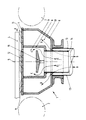
- a lower box forming part of a cooling device according to the invention is generally designated by the reference numeral 1. It is mounted between two transport rollers 2 and 3, shown diagrammatically in phantom, which symbolize a bank of rollers on which moves, in the direction of arrow A, a metallic product 4 to be cooled.
- the box is shown in cross section, the cutting plane being therefore parallel to the direction of movement of the metal product 4.
- the box 1 has a longitudinal plane of symmetry, which is a vertical plane whose trace 5 is shown in phantom.
- the box 1 rests on the frame of the roller bench by means of suitable supports.
- the lower box 1 has an outer wall 6, having the general shape of a U, which is closed by a front wall 7 parallel to the direction of movement of the product 4.
- a partition inner 8 which also has the general shape of a U and which is also closed by the front wall 7.
- the outer wall 6 and the partition 8, both in the shape of a U are each arranged symmetrically relative to the plane 5.
- the partition 8 delimits on the one hand, with a part of the front wall 7, an interior compartment 9 and on the other hand, with another part of the front wall 7 and with the outer wall 6, an outer compartment 10 which symmetrically surrounds the inner compartment 9.
- the front wall 7 is pierced with a plurality of orifices intended to allow the passage of the refrigerant in the direction of the metallic product 4.
- a part of these orifices in this case those which are designated by the reference 12, open out in the interior compartment 9, while other orifices, identified 11, open into the exterior compartment 10.
- these orifices are distributed in an appropriate manner in the front wall 7 to ensure repair.
- desired tition preferably a uniform distribution, of the refrigerant by one and / or the other of the compartments 9 and 10.
- the outer compartment 10 is equipped with supply lines 13 from which the refrigerant spreads in said compartment 10 according to the arrows B to reach the orifices 11.
- the interior compartment 9 is equipped with supply lines 14, which pass through sealingly the external compartment 10, and from which the refrigerant circulates according to the arrows C by turning the jet breaker 15, in the direction of the orifices 12.
- the jet breaker 15 is intended to ensure a uniform distribution of the pressure and the flow of coolant in all of the orifices 12
- the supply lines 13 and 14 are also distributed appropriately along the length of the lower box 1.
- Such a box can operate in different ways, depending on the specific flow rate of refrigerant, necessary to ensure the desired cooling of the metal product 4.
- specific flow rate is meant here the quantity, generally the volume of refrigerant per unit of surface of the product to be cooled.
- the refrigerant used is preferably water or an aqueous liquid.
- the quantity of heat to be extracted is greater the greater the drop in temperature to be ensured and the greater the thickness of the product. It is therefore necessary to apply a high specific flow rate of the refrigerant.
- the two compartments 9 and 10 are simultaneously supplied with refrigerant, and the box 1 then functions as a lower box of the known type.
- the invention is obviously not limited to feeding one or other of the exterior 10 and interior 9 compartments.
- the cooling device according to the invention thus offers a flexibility of operation that the known devices did not have.
- the invention is however not limited to the embodiment which has just been described and illustrated, but it also extends to the various possible variants coming within the scope of the following claims.
Landscapes
- Engineering & Computer Science (AREA)
- Mechanical Engineering (AREA)
- Heat Treatments In General, Especially Conveying And Cooling (AREA)
Abstract
Description
- La présente invention concerne un dispositif pour le refroidissement d'un produit métallique en mouvement. Elle s'applique particulièrement, mais pas exclusivement, au refroidissement des produits plats de grande largeur, notamment des tôles fortes.
- Un dispositif de ce type est déjà connu par le brevet BE-A-900.784. Ce dispositif connu comporte deux caissons transversaux perforés, disposés respectivement au-dessus et en dessous du produit métallique et distribuant l'agent réfrigérant de manière uniforme selon la largeur de ce produit métallique.
- On a cependant constaté que, dans les cas où le débit spécifique d'agent réfrigérant est faible, une quantité appréciable d'agent réfrigérant n'atteint pas la face inférieure du produit; le refroidissement de celui-ci n'est alors pas assuré de façon satisfaisante.
- La présente invention propose un moyen simple de remédier à cet inconvénient, par une modification appropriée du dispositif connu rappelé plus haut.
- Conformément à la présente invention, un dispositif pour le refroidissement d'un produit métallique en mouvement, qui comporte un caisson supérieur et un caisson inférieur disposés respectivement au dessus et en dessous de la trajectoire dudit produit métallique et orientés transversalement par rapport à ladite trajectoire, lesdits caissons étant pourvus, dans une paroi frontale, d'orifices de passage d'un agent réfrigérant en direction dudit produit métallique, est caractérisé en ce que le caisson inférieur est divisé en au moins deux compartiments sensiblement parallèles orientés suivant la direction longitudinale dudit caisson inférieur, en ce que ladite division en compartiments est réalisée par au moins une cloison sensiblement parallèle à la direction longitudinale dudit caisson inférieur et formant un angle avec ladite paroi frontale, et en ce que chacun desdits compartiments présente une partie desdits orifices de passage et comporte des moyens d'alimentation en agent réfrigérant.
- Selon une réalisation particulière du dispositif de l'invention, ladite cloison délimite d'une part avec une partie de ladite paroi frontale un premier compartiment, dit compartiment intérieur,qui est relié à une première source d'agent réfrigérant et d'autre part avec une autre partie de ladite paroi frontale et avec la paroi extérieure dudit caisson inférieur un second compartiment, dit compartiment extérieur qui entoure ledit compartiment intérieur et qui est relié à une seconde source d'agent réfrigérant.
- D'une façon avantageuse, ledit caisson inférieur possède un plan de symétrie longitudinal, et le compartiment intérieur, respectivement le compartiment extérieur, sont chacun agencés de façon symétrique par rapport audit plan de symétrie longitudinal.
- Par ailleurs, il est intéressant que lesdites première et seconde sources d'agent réfrigérant soient constituées par une source unique, qui alimente séparément lesdits deux compartiments, éventuellement sous des pressions différentes.
- D'autres particularités intéressantes de l'invention apparaîtront à la lecture de la description qui va suivre, donnée à titre de simple exemple, d'une réalisation préférée du dispositif de l'invention. Cette description se réfère au dessin annexé, dont la figure unique montre la section transversale d'un caisson inférieur divisé en deux compartiments de section symétrique.
- Dans cette figure unique, un caisson inférieur faisant partie d'un dispositif de refroidissement conforme à l'invention est globalement désigné par le repère numérique 1. Il est monté entre deux rouleaux de transport 2 et 3, schématisés en trait mixte, qui symbolisent un banc de rouleaux sur lequel se déplace, dans le sens de la flèche A, un produit métallique 4 à refroidir. Le caisson est représenté en coupe transversale, le plan de coupe étant de ce fait parallèle à la direction de déplacement du produit métallique 4. Dans la configuration représentée ici, le caisson 1 possède un plan de symétrie longitudinal, qui est un plan vertical dont la trace 5 est représentée en trait mixte. Le caisson 1 repose sur la charpente du banc de rouleaux par l'intermédiaire de supports appropriés.
- Le caisson inférieur 1 comporte une paroi extérieure 6, ayant la forme générale d'un U, qui est fermée par une paroi frontale 7 parallèle à la direction de déplacement du produit 4. A l'intérieur de la paroi extérieure 6 est disposée une cloison intérieure 8, qui présente également la forme générale d'un U et qui est également fermée par la paroi frontale 7. Comme le montre la figure, la paroi extérieure 6 et la cloison 8, toutes deux en forme de U, sont chacune agencées symétriquement par rapport au plan 5. Dans cette réalisation, la cloison 8 délimite d'une part, avec une partie de la paroi frontale 7, un compartiment intérieur 9 et d'autre part, avec une autre partie de la paroi frontale 7 et avec la paroi extérieure 6, un compartiment extérieur 10 qui entoure symétriquement le compartiment intérieur 9.
- La paroi frontale 7 est percée d'une pluralité d'orifices destinés à permettre le passage de l'agent réfrigérant en direction du produit métallique 4. Une partie de ces orifices, en l'occurrence ceux qui sont désignés par le repère 12, débouchent dans le compartiment intérieur 9, tandis que d'autres orifices, repérés 11, débouchent dans le compartiment extérieur 10. Bien entendu, ces orifices sont distribués de façon appropriée dans la paroi frontale 7 pour assurer la répar tition désirée, de préférence une répartition uniforme, de l'agent réfrigérant par l'un et/ou l'autre des compartiments 9 et 10.
- A l'arrière des deux compartiments 9 et 10, c'est-à-dire ici dans les parois constituant respectivement les âmes des U 6 et 8, sont prévus des moyens de raccordement à des sources d'agent réfrigérant, non représentées.
- Le compartiment extérieur 10 est équipé de conduites d'alimentation 13 à partir desquelles l'agent réfrigérant se répand dans ledit compartiment 10 suivant les flèches B pour gagner les orifices 11. Le compartiment intérieur 9 est équipé de conduites d'alimentation 14, qui traversent de façon étanche le compartiment extérieur 10, et à partir desquelles l'agent réfrigérant circule suivant les flèches C en cntournant le brise-jet 15, en direction des orifices 12. Le brise-jet 15 est destiné à assurer une répartition uniforme de la pression et du débit d'agent réfrigérant dans l'ensemble des orifices 12.
- Les conduites d'alimentation 13 et 14 sont également réparties de façon appropriée suivant la longueur du caisson inférieur 1.
- Un tel caisson peut fonctionner de différentes manières, en fonction du débit spécifique d'agent réfrigérant, nécessaire pour assurer le refroidissement désiré du produit métallique 4. Par débit spécifique, on entend ici la quantité, généralement le volume d'agent réfrigérant par unité de surface du produit à refroidir. Il faut en outre comprendre que l'agent réfrigérant utilisé est de préférence l'eau ou un liquide aqueux.
- Il peut être nécessaire d'abaisser fortement la température d'un produit métallique. Dans ce cas, la quantité de chaleur à extraire est d'autant plus grande que la chute de température à assurer est importante et que l'épaisseur du produit est forte. Il convient dès lors d'appliquer un débit spécifique élevé de l'agent réfrigérant. A cet effet, on alimente simultanément les deux compartiments 9 et 10 en agent réfrigérant, et le caisson 1 fonctionne alors comme un caisson inférieur du type connu.
- Il arrive cependant aussi que la chute de température à assurer, ainsi qu'éventuellement l'épaisseur du produit 4, ne nécessitent l'extraction que d'une quantité de chaleur relativement faible. Il en résulte une diminution parfois importante du débit spécifique de l'agent réfrigérant, et le risque, avec un caisson classique, qu'une partie de l'agent réfrigérant n'atteigne pas le produit à refroidir.
- Dans ce cas, il est possible, avec un caisson in érieur conforme à l'invention, de n'alimenter qu'un seul compartiment, afin de concentrer le débit spécifique faible sur un plus petit nombre d'orifices. Le débit de chaque orifice est ainsi augmenté et l'agent réfrigérant atteint plus aisément le produit métallique 4 à refroidir.
- L'invention n'est évidemment pas limitée à l'alimentation de l'un ou l'autre des compartiments extérieur 10 et intérieur 9.
- Il s'est cependant avéré avantageux d'alimenter de préférence le compartiment extérieur 10, qui délivre l'agent réfrigérant dans les deux zones de bord du caisson 1, alors que le compartiment intérieur 9 n'est pas alimenté. Il en résulte un avantage hydraulique, du à un meilleur écoulement de l'agent réfrigérant, et un avantage métallurgique dû à une meilleure répartition du refroidissement suivant la longueur du produit mùétallique.
- Le dispositif de refroidissement conforme à l'invention offre ainsi une souplesse de fonctionnement que ne présentaient pas les dispositifs connus. L'invention n'est cependant pas limitée au mode de réalisation qui vient d'être décrit et illustré, mais elle s'étend également aux différentes variantes possibles entrant dans le cadre des revendications suivantes.
Claims (7)
Applications Claiming Priority (2)
| Application Number | Priority Date | Filing Date | Title |
|---|---|---|---|
| BE8700720A BE1000674A6 (fr) | 1987-06-26 | 1987-06-26 | Dispositif pour le refroidissement d'un produit metallique en mouvement. |
| BE8700720 | 1987-06-26 |
Publications (3)
| Publication Number | Publication Date |
|---|---|
| EP0297077A2 true EP0297077A2 (fr) | 1988-12-28 |
| EP0297077A3 EP0297077A3 (en) | 1989-10-04 |
| EP0297077B1 EP0297077B1 (fr) | 1993-06-09 |
Family
ID=3882739
Family Applications (1)
| Application Number | Title | Priority Date | Filing Date |
|---|---|---|---|
| EP19880870111 Expired - Lifetime EP0297077B1 (fr) | 1987-06-26 | 1988-06-22 | Dispositif pour le refroidissement d'un produit métallique en mouvement. |
Country Status (3)
| Country | Link |
|---|---|
| EP (1) | EP0297077B1 (fr) |
| BE (1) | BE1000674A6 (fr) |
| DE (1) | DE3881585D1 (fr) |
Families Citing this family (1)
| Publication number | Priority date | Publication date | Assignee | Title |
|---|---|---|---|---|
| EP1938911A1 (fr) | 2006-12-27 | 2008-07-02 | VAI Industries (UK) Ltd. | Dispositif et procédé pour refroidissement contrôlé |
Family Cites Families (6)
| Publication number | Priority date | Publication date | Assignee | Title |
|---|---|---|---|---|
| US3687145A (en) * | 1970-06-26 | 1972-08-29 | Inland Steel Co | Quench system |
| US3941611A (en) * | 1974-11-04 | 1976-03-02 | Wean United, Inc. | Apparatus for cooling strip like material |
| BE851382A (fr) * | 1977-02-11 | 1977-05-31 | Centre Rech Metallurgique | Perfectionnements aux procedes et aux dispositifs pour combattre le bombage des cylindres de laminoir |
| DE3147878A1 (de) * | 1981-12-03 | 1983-06-16 | SMS Schloemann-Siemag AG, 4000 Düsseldorf | Vorrichtung zum kuehlen von flachem walzgut |
| BE900784A (fr) * | 1984-10-09 | 1985-04-09 | Centre Rech Metallurgique | Dispositif pour refroidir un produit metallique en mouvement et installation en comportant l'apllication. |
| BE904177A (fr) * | 1986-02-05 | 1986-08-05 | Centre Rech Metallurgique | Dispositif de refroidissement d'un produit metallique en mouvement. |
-
1987
- 1987-06-26 BE BE8700720A patent/BE1000674A6/fr not_active IP Right Cessation
-
1988
- 1988-06-22 DE DE8888870111T patent/DE3881585D1/de not_active Expired - Lifetime
- 1988-06-22 EP EP19880870111 patent/EP0297077B1/fr not_active Expired - Lifetime
Also Published As
| Publication number | Publication date |
|---|---|
| DE3881585D1 (de) | 1993-07-15 |
| EP0297077B1 (fr) | 1993-06-09 |
| BE1000674A6 (fr) | 1989-03-07 |
| EP0297077A3 (en) | 1989-10-04 |
Similar Documents
| Publication | Publication Date | Title |
|---|---|---|
| FR2748410A1 (fr) | Procede et machine de brasage ou etamage a la vague | |
| AU4580697A (en) | Apparatus for screening | |
| FR2631353A1 (fr) | Dispositif d'alimentation en melange pateux | |
| EP0239708A1 (fr) | Dispositif de pasteurisation de produits alimentaires contenus dans des récipients | |
| EP0113610B1 (fr) | Meuble présentoir réfrigéré | |
| EP0297077B1 (fr) | Dispositif pour le refroidissement d'un produit métallique en mouvement. | |
| EP0178281A2 (fr) | Installation pour le refroidissement d'un produit métallique en mouvement | |
| EP1218128B1 (fr) | Cylindre de coulee continue de bande metallique comprenant un circuit de refroidissement | |
| FR2618216A1 (fr) | Dispositif pour fondre des metaux dans une chambre a vide par bombardement electronique, notamment en vue de leur purification. | |
| EP0233854B1 (fr) | Dispositif de refroidissement d'un produit métallique en mouvement | |
| FR2491513A1 (fr) | Dispositif de revetement de feuilles en deplacement | |
| EP0319417A1 (fr) | Guide-jet pour installations sanitaires | |
| EP0327526B1 (fr) | Dispositif de refroidissement d'un métal pendant la coulée | |
| EP1086315B1 (fr) | Oscillateur fluidique, piece destinee a etre incorporee dans un oscillateur fluidique et procede de fabrication d'un tel oscillateur fluidique | |
| EP3112793B1 (fr) | Dispositif de distribution de film tombant sur un échangeur à plaques comprenant des premier et deuxième étages de distribution | |
| EP0961698A1 (fr) | Dispositif de chauffage-climatisation integre dans une planche de bord de vehicule automobile | |
| BE657349A (fr) | ||
| CH637757A5 (en) | Refrigeration enclosure | |
| EP0407323A1 (fr) | Procédé et dispositif de coulée continue entre cylindres de produits métalliques minces aptes au laminage à froid direct | |
| FR2530986A1 (fr) | Structure de support de metal pour des machines de fonderie en continu | |
| WO1990008003A1 (fr) | Dispositif pour la fixation et le refroidissement d'un bloc en graphite d'une paroi en graphite d'un moule | |
| FR2602156A1 (fr) | Dispositif pour projeter un fluide de traitement sur une bande de matiere defilant longitudinalement | |
| EP4732642A1 (fr) | Dispositif de refroidissement configure pour refroidir un module electronique | |
| FR2799447A1 (fr) | Distributeur de produits de forme cylindrique | |
| BE554111A (fr) |
Legal Events
| Date | Code | Title | Description |
|---|---|---|---|
| PUAI | Public reference made under article 153(3) epc to a published international application that has entered the european phase |
Free format text: ORIGINAL CODE: 0009012 |
|
| AK | Designated contracting states |
Kind code of ref document: A2 Designated state(s): BE DE ES FR GB IT LU NL SE |
|
| PUAL | Search report despatched |
Free format text: ORIGINAL CODE: 0009013 |
|
| AK | Designated contracting states |
Kind code of ref document: A3 Designated state(s): BE DE ES FR GB IT LU NL SE |
|
| 17P | Request for examination filed |
Effective date: 19900327 |
|
| 17Q | First examination report despatched |
Effective date: 19910814 |
|
| GRAA | (expected) grant |
Free format text: ORIGINAL CODE: 0009210 |
|
| AK | Designated contracting states |
Kind code of ref document: B1 Designated state(s): BE DE ES FR GB IT LU NL SE |
|
| PG25 | Lapsed in a contracting state [announced via postgrant information from national office to epo] |
Ref country code: IT Free format text: LAPSE BECAUSE OF FAILURE TO SUBMIT A TRANSLATION OF THE DESCRIPTION OR TO PAY THE FEE WITHIN THE PRE;WARNING: LAPSES OF ITALIAN PATENTS WITH EFFECTIVE DATE BEFORE 2007 MAY HAVE OCCURRED AT ANY TIME BEFORE 2007. THE CORRECT EFFECTIVE DATE MAY BE DIFFERENT FROM THE ONE RECORDED.SCRIBED TIME-LIMIT Effective date: 19930609 Ref country code: DE Effective date: 19930609 Ref country code: NL Effective date: 19930609 Ref country code: ES Free format text: THE PATENT HAS BEEN ANNULLED BY A DECISION OF A NATIONAL AUTHORITY Effective date: 19930609 |
|
| PG25 | Lapsed in a contracting state [announced via postgrant information from national office to epo] |
Ref country code: LU Free format text: LAPSE BECAUSE OF NON-PAYMENT OF DUE FEES Effective date: 19930630 |
|
| REF | Corresponds to: |
Ref document number: 3881585 Country of ref document: DE Date of ref document: 19930715 |
|
| GBT | Gb: translation of ep patent filed (gb section 77(6)(a)/1977) |
Effective date: 19930810 |
|
| NLV1 | Nl: lapsed or annulled due to failure to fulfill the requirements of art. 29p and 29m of the patents act | ||
| PLBE | No opposition filed within time limit |
Free format text: ORIGINAL CODE: 0009261 |
|
| STAA | Information on the status of an ep patent application or granted ep patent |
Free format text: STATUS: NO OPPOSITION FILED WITHIN TIME LIMIT |
|
| 26N | No opposition filed | ||
| EAL | Se: european patent in force in sweden |
Ref document number: 88870111.7 |
|
| PGFP | Annual fee paid to national office [announced via postgrant information from national office to epo] |
Ref country code: GB Payment date: 19950612 Year of fee payment: 8 |
|
| PGFP | Annual fee paid to national office [announced via postgrant information from national office to epo] |
Ref country code: FR Payment date: 19950906 Year of fee payment: 8 |
|
| PG25 | Lapsed in a contracting state [announced via postgrant information from national office to epo] |
Ref country code: GB Effective date: 19960622 |
|
| GBPC | Gb: european patent ceased through non-payment of renewal fee |
Effective date: 19960622 |
|
| PG25 | Lapsed in a contracting state [announced via postgrant information from national office to epo] |
Ref country code: FR Effective date: 19970228 |
|
| REG | Reference to a national code |
Ref country code: FR Ref legal event code: ST |
|
| PGFP | Annual fee paid to national office [announced via postgrant information from national office to epo] |
Ref country code: BE Payment date: 20010514 Year of fee payment: 14 |
|
| PGFP | Annual fee paid to national office [announced via postgrant information from national office to epo] |
Ref country code: SE Payment date: 20010529 Year of fee payment: 14 |
|
| PG25 | Lapsed in a contracting state [announced via postgrant information from national office to epo] |
Ref country code: SE Free format text: LAPSE BECAUSE OF NON-PAYMENT OF DUE FEES Effective date: 20020623 |
|
| PG25 | Lapsed in a contracting state [announced via postgrant information from national office to epo] |
Ref country code: BE Free format text: LAPSE BECAUSE OF NON-PAYMENT OF DUE FEES Effective date: 20020630 |
|
| BERE | Be: lapsed |
Owner name: CENTRE DE RECHERCHES *METALLURGIQUES CENTRUM VOOR Effective date: 20020630 |
|
| EUG | Se: european patent has lapsed |