EP2096409A2 - Gehefteter Wellenleiter zur Verwendung in einem faseroptischen Gyroskop - Google Patents
Gehefteter Wellenleiter zur Verwendung in einem faseroptischen Gyroskop Download PDFInfo
- Publication number
- EP2096409A2 EP2096409A2 EP09152742A EP09152742A EP2096409A2 EP 2096409 A2 EP2096409 A2 EP 2096409A2 EP 09152742 A EP09152742 A EP 09152742A EP 09152742 A EP09152742 A EP 09152742A EP 2096409 A2 EP2096409 A2 EP 2096409A2
- Authority
- EP
- European Patent Office
- Prior art keywords
- waveguide
- waveguide portions
- circuit
- coupled
- branch sections
- Prior art date
- Legal status (The legal status is an assumption and is not a legal conclusion. Google has not performed a legal analysis and makes no representation as to the accuracy of the status listed.)
- Granted
Links
Images


Classifications
-
- G—PHYSICS
- G01—MEASURING; TESTING
- G01C—MEASURING DISTANCES, LEVELS OR BEARINGS; SURVEYING; NAVIGATION; GYROSCOPIC INSTRUMENTS; PHOTOGRAMMETRY OR VIDEOGRAMMETRY
- G01C19/00—Gyroscopes; Turn-sensitive devices using vibrating masses; Turn-sensitive devices without moving masses; Measuring angular rate using gyroscopic effects
- G01C19/58—Turn-sensitive devices without moving masses
- G01C19/64—Gyrometers using the Sagnac effect, i.e. rotation-induced shifts between counter-rotating electromagnetic beams
- G01C19/72—Gyrometers using the Sagnac effect, i.e. rotation-induced shifts between counter-rotating electromagnetic beams with counter-rotating light beams in a passive ring, e.g. fibre laser gyrometers
- G01C19/721—Details, e.g. optical or electronical details
Definitions
- a fiber optic gyroscope uses the interference of light to measure angular velocity. Rotation is sensed in a FOG with a large coil of optical fiber forming a Sagnac interferometer. To measure rotation, two light beams are introduced into the coil in opposite directions by an electro-optic modulating device such as an integrated optical circuit (IOC). If the coil is undergoing a rotation, then the beam traveling in the direction of rotation will experience a longer path to the other end of the fiber than the beam traveling against the rotation. This is known as the Sagnac effect.
- IOC integrated optical circuit
- the phase shift between the counter-rotating beams due to the Sagnac effect and modulation in the IOC causes the beams to interfere, resulting in a combined beam, the intensity and phase of which depends on the angular velocity of the coil.
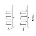
- V ⁇ ( t ) the voltage across the electrodes changes the phase of light in a waveguide by ⁇ .
- ⁇ ( t ) follows the shape of the trace of V ⁇ ( t ) exactly.
- V ⁇ ( t ) the voltage across the electrodes changes the phase of light in a waveguide by ⁇ .
- ⁇ ( t ) follows the shape of the trace of V ⁇ ( t ) exactly.
- ⁇ ( t ) is corrupted, as shown in the lower trace as ⁇ ⁇ ( t ), and overshoots the desired ⁇ at both the up and down voltage steps.
- an integrated optical circuit includes a first waveguide portion of a first material.
- the first waveguide portion includes an input-port section terminating in a junction section of the first waveguide portion from which first and second branch sections of the first waveguide portion are formed.
- Second and third waveguide portions are respectively coupled to the first and second branch sections.
- the second and third waveguide portions are diffused with a second material different from the first material.
- First and second modulators are respectively coupled to the second and third waveguide portions. Each of the modulators provides respective modulating voltages generating respective electric fields across the second and third waveguide portions.
- the second and third waveguide portions are coupled to the first and second branch sections at respective locations where the modulating electric fields are substantially zero.
- FIGURE 1 illustrates in graphical form the RDS effect of corrupted modulation in an IOC
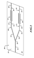
- FIGURE 2 illustrates a FOG according to an embodiment of the present invention
- FIGURE 3 illustrates an IOC according to an embodiment of the present invention.
- FIGURE 4 illustrates the extinction ratio of a misaligned stitch.
- an optical circuit of a Sagnac gyroscope may be comprised of an IOC, a light source, polarizing circulator, detector, and fiber coil.
- An embodiment may employ crystalline LiNbO 3 integrated IOCs useful in navigation grade gyros because an applied voltage changes the refractive index of the LiNbO 3 . This property provides superior performance in closed loop gyros by allowing fast, accurate, and sophisticated modulation of light transiting the rate-sensing coil.
- LiNbO 3 IOCs by diffusing titanium (Ti) waveguides into LiNbO 3 designed to create a y-junction.
- a fiber containing light from a fiber laser is attached to the single tail of the y, and the two ends of a fiber coil were attached to the two outputs of the y-junction.
- FIG. 2 illustrates a FOG system 100 according to an embodiment of the present invention.
- a light source 105 provides an optical signal or beam to an optional coupler 110, which may function to redirect a portion of the beam to a detector 120.
- the remainder of the beam may be supplied to an IOC 115 of a sensing-loop assembly 125, having a fiber coil 126, via a circulator element 130 that is, in turn, coupled to the detector 120.
- FIG. 3 illustrates an IOC 115 according to an embodiment of the invention.
- the IOC 115 includes a first proton-exchanged waveguide portion 200.
- the first waveguide portion 200 includes an input-port section 205 terminating in a junction section (y-junction) 210 from which first and second branch sections 215, 220 are formed.
- the first and second branch sections 215, 220 include respective bent regions 260, 265.
- the bent regions 260, 265 may have an angular "elbow" configuration as illustrated in FIG. 3 , or may be configured with a less-severe, more rounded radius of curvature than that illustrated.
- Titanium-diffused waveguide portions 225, 230 are respectively coupled to the first and second branch sections 215, 220.
- First and second modulators such as electrodes 235, 240, are respectively coupled to the waveguide portions 225, 230.
- Each of the electrodes 235, 240 provide respective modulating voltages generating respective electric fields.
- the IOC 115 may further include second and third proton-exchanged waveguide portions 245, 250 coupled to the waveguide portions 225, 230.
- Stitching involves creating connected segments of Ti-diffused and proton-exchanged waveguides on the same substrate 255.
- the waveguide portions 225, 230 are stitched, or otherwise coupled, to the first and second branch sections 215, 220 at respective locations 270, 275 where the electric fields produced by the electrodes 235, 240 are substantially zero.
- the second and third proton-exchanged waveguide portions 245, 250 are stitched to the waveguide portions 225, 230 at respective locations 280, 285 where the electric fields produced by the electrodes 235, 240 are substantially zero.
- the stitching occurs far enough from the electrodes 235, 240 such that the proton-exchanged waveguides 200, 245, 250 are unaffected by electric fields associated with modulation voltages.
- the respective locations 270, 275 are approximately halfway between the electrodes 235, 240 and the bent regions 260, 265. As such, the stitching occurs a distance away from the bent regions 260, 265 sufficient to avoid modal transition effects that may occur at the bent regions.
- waveguides may be physically formed by well known processes for diffusing Ti or H+ along the crystal planes which develop the birefringence in the crystal, the angular alignment between the fast and slow axes of the stitched waveguides is virtually perfect, a property that maintains the very high extinction ratio provided by the proton exchange waveguides.
- anisotropic substances such as a birefringent crystal
- electric vectors oscillate normal to the propagation vector in orthogonal planes ( H and V ).
- the azimuths and refractive indices of H and V are determined by the stoichiometric arrangement of the molecules comprising the crystal.
- the refractive index is proportional to the area density of atoms in the respective H and V planes (viz., atoms/mm 2 ); the birefringence is proportional to the difference of the refractive indices along the planes.
- FIG. 4 illustrates the extinction ratio of a misaligned stitch.
- the stitching occurs in portions of the waveguides that are parallel, or very nearly parallel, to the crystal planes.
- the LiNbO 3 crystal planes determine the alignment of both the birefringent axes in Ti-diffused waveguides, and the pass axis of the light in proton-exchanged waveguides. This makes the angular alignment at the stitch nearly perfect, thus avoiding gyro rate errors due to angular misalignments in the IOC.
- the extinction ratio of the stitched waveguide IOC 115 which includes polarizing proton-exchanged waveguides and Ti-diffused waveguides, is substantially the same as that of a proton-exchanged IOC.
Landscapes
- Physics & Mathematics (AREA)
- Engineering & Computer Science (AREA)
- Optics & Photonics (AREA)
- Electromagnetism (AREA)
- Power Engineering (AREA)
- General Physics & Mathematics (AREA)
- Radar, Positioning & Navigation (AREA)
- Remote Sensing (AREA)
- Gyroscopes (AREA)
- Optical Integrated Circuits (AREA)
- Optical Modulation, Optical Deflection, Nonlinear Optics, Optical Demodulation, Optical Logic Elements (AREA)
Applications Claiming Priority (1)
| Application Number | Priority Date | Filing Date | Title |
|---|---|---|---|
| US12/040,866 US20090219545A1 (en) | 2008-02-29 | 2008-02-29 | Stitched waveguide for use in a fiber-optic gyroscope |
Publications (3)
| Publication Number | Publication Date |
|---|---|
| EP2096409A2 true EP2096409A2 (de) | 2009-09-02 |
| EP2096409A3 EP2096409A3 (de) | 2009-09-30 |
| EP2096409B1 EP2096409B1 (de) | 2011-03-23 |
Family
ID=40639725
Family Applications (1)
| Application Number | Title | Priority Date | Filing Date |
|---|---|---|---|
| EP09152742A Not-in-force EP2096409B1 (de) | 2008-02-29 | 2009-02-12 | Gehefteter Wellenleiter zur Verwendung in einem faseroptischen Gyroskop |
Country Status (4)
| Country | Link |
|---|---|
| US (1) | US20090219545A1 (de) |
| EP (1) | EP2096409B1 (de) |
| JP (1) | JP2009210573A (de) |
| DE (1) | DE602009000925D1 (de) |
Families Citing this family (8)
| Publication number | Priority date | Publication date | Assignee | Title |
|---|---|---|---|---|
| US8717575B2 (en) | 2011-08-17 | 2014-05-06 | Honeywell International Inc. | Systems and methods for environmentally insensitive high-performance fiber-optic gyroscopes |
| US8463081B1 (en) | 2011-12-09 | 2013-06-11 | Jds Uniphase Corporation | Optical phase modulator |
| US9395184B2 (en) | 2014-08-18 | 2016-07-19 | Honeywell International Inc. | Resonant fiber optic gyroscope with polarizing crystal waveguide coupler |
| US9644966B2 (en) | 2014-09-11 | 2017-05-09 | Honeywell International Inc. | Integrated optic circuit with waveguides stitched at supplementary angles for reducing coherent backscatter |
| US9766071B2 (en) * | 2015-01-23 | 2017-09-19 | Honeywell International Inc. | Diverging waveguide atomic gyroscope |
| WO2018132659A1 (en) | 2017-01-13 | 2018-07-19 | The Charles Stark Draper Laboratory, Inc. | Fiber management assembly for multi-axis fiber optic gyroscope |
| US11294120B2 (en) * | 2020-05-07 | 2022-04-05 | Honeywell International Inc. | Integrated environmentally insensitive modulator for interferometric gyroscopes |
| CN112066973B (zh) * | 2020-09-14 | 2022-08-23 | 浙江大学 | 一种铌酸锂波导的集成光子晶体光纤陀螺 |
Family Cites Families (6)
| Publication number | Priority date | Publication date | Assignee | Title |
|---|---|---|---|---|
| FR2616538B1 (fr) * | 1987-06-11 | 1989-09-01 | Alsthom | Systeme interferometrique a fibre optique de type sagnac |
| US5749132A (en) * | 1995-08-30 | 1998-05-12 | Ramar Corporation | Method of fabrication an optical waveguide |
| US5982964A (en) * | 1997-06-30 | 1999-11-09 | Uniphase Corporation | Process for fabrication and independent tuning of multiple integrated optical directional couplers on a single substrate |
| JP3692474B2 (ja) * | 2002-11-01 | 2005-09-07 | 日本航空電子工業株式会社 | 光ファイバジャイロ |
| US7212326B2 (en) * | 2003-05-30 | 2007-05-01 | Jds Uniphase Corporation | Optical external modulator |
| JP5412832B2 (ja) * | 2007-01-23 | 2014-02-12 | 株式会社村田製作所 | 光制御素子 |
-
2008
- 2008-02-29 US US12/040,866 patent/US20090219545A1/en not_active Abandoned
-
2009
- 2009-02-12 EP EP09152742A patent/EP2096409B1/de not_active Not-in-force
- 2009-02-12 DE DE602009000925T patent/DE602009000925D1/de active Active
- 2009-02-19 JP JP2009036604A patent/JP2009210573A/ja not_active Ceased
Also Published As
| Publication number | Publication date |
|---|---|
| US20090219545A1 (en) | 2009-09-03 |
| DE602009000925D1 (de) | 2011-05-05 |
| JP2009210573A (ja) | 2009-09-17 |
| EP2096409A3 (de) | 2009-09-30 |
| EP2096409B1 (de) | 2011-03-23 |
Similar Documents
| Publication | Publication Date | Title |
|---|---|---|
| EP2096409B1 (de) | Gehefteter Wellenleiter zur Verwendung in einem faseroptischen Gyroskop | |
| KR102551725B1 (ko) | 간섭형 광섬유 자이로스코프(ifog)에 대한 광자 집적 회로 | |
| EP0262825B1 (de) | Faseroptischer Rotationssensor mit einer Faser hoher Doppelbrechung und niedriger Phasenfehlerintensität | |
| US9644966B2 (en) | Integrated optic circuit with waveguides stitched at supplementary angles for reducing coherent backscatter | |
| US7973938B2 (en) | Bias-reduced fiber optic gyroscope with polarizing fibers | |
| US9395184B2 (en) | Resonant fiber optic gyroscope with polarizing crystal waveguide coupler | |
| EP3447446B1 (de) | Systeme und verfahren zur reduzierung von polarisationsbedingten bias-fehlern in rfogs | |
| US5037205A (en) | Integrated optic interferometric fiber gyroscope module and method | |
| US8373863B2 (en) | Stitched waveguide for use in a fiber-optic gyroscope | |
| US5137356A (en) | Fiber optic resonator interferometer gyroscope having a resonator loop formed of two coupled lengths of optical fiber | |
| EP0502196B1 (de) | Gerät zum messen der winkelgeschwindigkeit durch optische interferenz | |
| EP0373200B1 (de) | Sagnac-Ring Rotations-Sensor und Verfahren zu dessen Verwendung | |
| CN103837931A (zh) | 用于光纤陀螺的新型偏振环行y波导结构 | |
| EP0416070B1 (de) | Unipolarisation enthaltende, integriert-optische bauteile für optische gyroskope | |
| US20170370723A1 (en) | Electro-optical Phase Modulator Having Stitched-in Vacuum Stable Waveguide with Minimized Conductivity Contrast | |
| JP2004309466A (ja) | 光ファイバジャイロ | |
| Minford et al. | Fiber optic gyroscope using an eight-component LiNbO3 integrated optic circuit | |
| JP2849733B2 (ja) | 光ファイバジャイロ | |
| JPS622121A (ja) | 光フアイバジヤイロスコ−プ | |
| Laznicka Jr et al. | Medium-accuracy fiber optic gyroscope using integrated optical circuit technology | |
| JPH08297218A (ja) | 光集積回路及び光ファイバジャイロ | |
| JPH02136806A (ja) | 光方向性結合器及びそれを用いた回転角速度センサ | |
| JPH0758197B2 (ja) | 光ファイバジャイロ |
Legal Events
| Date | Code | Title | Description |
|---|---|---|---|
| PUAI | Public reference made under article 153(3) epc to a published international application that has entered the european phase |
Free format text: ORIGINAL CODE: 0009012 |
|
| PUAL | Search report despatched |
Free format text: ORIGINAL CODE: 0009013 |
|
| 17P | Request for examination filed |
Effective date: 20090212 |
|
| AK | Designated contracting states |
Kind code of ref document: A2 Designated state(s): AT BE BG CH CY CZ DE DK EE ES FI FR GB GR HR HU IE IS IT LI LT LU LV MC MK MT NL NO PL PT RO SE SI SK TR |
|
| AX | Request for extension of the european patent |
Extension state: AL BA RS |
|
| AK | Designated contracting states |
Kind code of ref document: A3 Designated state(s): AT BE BG CH CY CZ DE DK EE ES FI FR GB GR HR HU IE IS IT LI LT LU LV MC MK MT NL NO PL PT RO SE SI SK TR |
|
| AX | Request for extension of the european patent |
Extension state: AL BA RS |
|
| AKX | Designation fees paid |
Designated state(s): DE FR GB IT |
|
| GRAP | Despatch of communication of intention to grant a patent |
Free format text: ORIGINAL CODE: EPIDOSNIGR1 |
|
| GRAS | Grant fee paid |
Free format text: ORIGINAL CODE: EPIDOSNIGR3 |
|
| GRAA | (expected) grant |
Free format text: ORIGINAL CODE: 0009210 |
|
| AK | Designated contracting states |
Kind code of ref document: B1 Designated state(s): DE FR GB IT |
|
| REG | Reference to a national code |
Ref country code: GB Ref legal event code: FG4D |
|
| REF | Corresponds to: |
Ref document number: 602009000925 Country of ref document: DE Date of ref document: 20110505 Kind code of ref document: P |
|
| REG | Reference to a national code |
Ref country code: DE Ref legal event code: R096 Ref document number: 602009000925 Country of ref document: DE Effective date: 20110505 |
|
| PLBE | No opposition filed within time limit |
Free format text: ORIGINAL CODE: 0009261 |
|
| STAA | Information on the status of an ep patent application or granted ep patent |
Free format text: STATUS: NO OPPOSITION FILED WITHIN TIME LIMIT |
|
| 26N | No opposition filed |
Effective date: 20111227 |
|
| REG | Reference to a national code |
Ref country code: DE Ref legal event code: R097 Ref document number: 602009000925 Country of ref document: DE Effective date: 20111227 |
|
| PGFP | Annual fee paid to national office [announced via postgrant information from national office to epo] |
Ref country code: GB Payment date: 20150126 Year of fee payment: 7 |
|
| REG | Reference to a national code |
Ref country code: FR Ref legal event code: PLFP Year of fee payment: 8 |
|
| PGFP | Annual fee paid to national office [announced via postgrant information from national office to epo] |
Ref country code: DE Payment date: 20160302 Year of fee payment: 8 Ref country code: IT Payment date: 20160210 Year of fee payment: 8 |
|
| GBPC | Gb: european patent ceased through non-payment of renewal fee |
Effective date: 20160212 |
|
| REG | Reference to a national code |
Ref country code: FR Ref legal event code: PLFP Year of fee payment: 9 |
|
| PG25 | Lapsed in a contracting state [announced via postgrant information from national office to epo] |
Ref country code: GB Free format text: LAPSE BECAUSE OF NON-PAYMENT OF DUE FEES Effective date: 20160212 |
|
| REG | Reference to a national code |
Ref country code: DE Ref legal event code: R119 Ref document number: 602009000925 Country of ref document: DE |
|
| PG25 | Lapsed in a contracting state [announced via postgrant information from national office to epo] |
Ref country code: DE Free format text: LAPSE BECAUSE OF NON-PAYMENT OF DUE FEES Effective date: 20170901 |
|
| REG | Reference to a national code |
Ref country code: FR Ref legal event code: PLFP Year of fee payment: 10 |
|
| PG25 | Lapsed in a contracting state [announced via postgrant information from national office to epo] |
Ref country code: IT Free format text: LAPSE BECAUSE OF NON-PAYMENT OF DUE FEES Effective date: 20170212 |
|
| PGFP | Annual fee paid to national office [announced via postgrant information from national office to epo] |
Ref country code: FR Payment date: 20220224 Year of fee payment: 14 |
|
| P01 | Opt-out of the competence of the unified patent court (upc) registered |
Effective date: 20230525 |
|
| PG25 | Lapsed in a contracting state [announced via postgrant information from national office to epo] |
Ref country code: FR Free format text: LAPSE BECAUSE OF NON-PAYMENT OF DUE FEES Effective date: 20230228 |