EP2096246B1 - Dispositif avec un système de rails, au moins un support et un méchanisme de transport pour un tel dispositif - Google Patents
Dispositif avec un système de rails, au moins un support et un méchanisme de transport pour un tel dispositif Download PDFInfo
- Publication number
- EP2096246B1 EP2096246B1 EP09153572.4A EP09153572A EP2096246B1 EP 2096246 B1 EP2096246 B1 EP 2096246B1 EP 09153572 A EP09153572 A EP 09153572A EP 2096246 B1 EP2096246 B1 EP 2096246B1
- Authority
- EP
- European Patent Office
- Prior art keywords
- carrier
- running surfaces
- transport mechanism
- shaped body
- track
- Prior art date
- Legal status (The legal status is an assumption and is not a legal conclusion. Google has not performed a legal analysis and makes no representation as to the accuracy of the status listed.)
- Not-in-force
Links
- 230000007723 transport mechanism Effects 0.000 title claims description 57
- 239000000969 carrier Substances 0.000 claims description 5
- 230000002093 peripheral effect Effects 0.000 claims description 3
- 230000003319 supportive effect Effects 0.000 claims description 2
- 238000010276 construction Methods 0.000 description 5
- 238000006073 displacement reaction Methods 0.000 description 4
- 238000001125 extrusion Methods 0.000 description 3
- 230000003014 reinforcing effect Effects 0.000 description 2
- 229910000831 Steel Inorganic materials 0.000 description 1
- XAGFODPZIPBFFR-UHFFFAOYSA-N aluminium Chemical compound [Al] XAGFODPZIPBFFR-UHFFFAOYSA-N 0.000 description 1
- 229910052782 aluminium Inorganic materials 0.000 description 1
- 239000004411 aluminium Substances 0.000 description 1
- 238000004519 manufacturing process Methods 0.000 description 1
- 238000009420 retrofitting Methods 0.000 description 1
- 239000010959 steel Substances 0.000 description 1
Images


Classifications
-
- E—FIXED CONSTRUCTIONS
- E05—LOCKS; KEYS; WINDOW OR DOOR FITTINGS; SAFES
- E05D—HINGES OR SUSPENSION DEVICES FOR DOORS, WINDOWS OR WINGS
- E05D15/00—Suspension arrangements for wings
- E05D15/06—Suspension arrangements for wings for wings sliding horizontally more or less in their own plane
- E05D15/0604—Suspension arrangements for wings for wings sliding horizontally more or less in their own plane allowing an additional movement
- E05D15/0608—Suspension arrangements for wings for wings sliding horizontally more or less in their own plane allowing an additional movement caused by track lay-out
- E05D15/0613—Suspension arrangements for wings for wings sliding horizontally more or less in their own plane allowing an additional movement caused by track lay-out with multi-directional trolleys
-
- E—FIXED CONSTRUCTIONS
- E05—LOCKS; KEYS; WINDOW OR DOOR FITTINGS; SAFES
- E05Y—INDEXING SCHEME ASSOCIATED WITH SUBCLASSES E05D AND E05F, RELATING TO CONSTRUCTION ELEMENTS, ELECTRIC CONTROL, POWER SUPPLY, POWER SIGNAL OR TRANSMISSION, USER INTERFACES, MOUNTING OR COUPLING, DETAILS, ACCESSORIES, AUXILIARY OPERATIONS NOT OTHERWISE PROVIDED FOR, APPLICATION THEREOF
- E05Y2201/00—Constructional elements; Accessories therefor
- E05Y2201/60—Suspension or transmission members; Accessories therefor
- E05Y2201/606—Accessories therefor
- E05Y2201/61—Cooperation between suspension or transmission members
- E05Y2201/612—Cooperation between suspension or transmission members between carriers and rails
-
- E—FIXED CONSTRUCTIONS
- E05—LOCKS; KEYS; WINDOW OR DOOR FITTINGS; SAFES
- E05Y—INDEXING SCHEME ASSOCIATED WITH SUBCLASSES E05D AND E05F, RELATING TO CONSTRUCTION ELEMENTS, ELECTRIC CONTROL, POWER SUPPLY, POWER SIGNAL OR TRANSMISSION, USER INTERFACES, MOUNTING OR COUPLING, DETAILS, ACCESSORIES, AUXILIARY OPERATIONS NOT OTHERWISE PROVIDED FOR, APPLICATION THEREOF
- E05Y2201/00—Constructional elements; Accessories therefor
- E05Y2201/60—Suspension or transmission members; Accessories therefor
- E05Y2201/622—Suspension or transmission members elements
- E05Y2201/688—Rollers
- E05Y2201/692—Rollers having vertical axes
-
- E—FIXED CONSTRUCTIONS
- E05—LOCKS; KEYS; WINDOW OR DOOR FITTINGS; SAFES
- E05Y—INDEXING SCHEME ASSOCIATED WITH SUBCLASSES E05D AND E05F, RELATING TO CONSTRUCTION ELEMENTS, ELECTRIC CONTROL, POWER SUPPLY, POWER SIGNAL OR TRANSMISSION, USER INTERFACES, MOUNTING OR COUPLING, DETAILS, ACCESSORIES, AUXILIARY OPERATIONS NOT OTHERWISE PROVIDED FOR, APPLICATION THEREOF
- E05Y2800/00—Details, accessories and auxiliary operations not otherwise provided for
- E05Y2800/20—Combinations of elements
- E05Y2800/21—Combinations of elements of identical elements, e.g. of identical compression springs
-
- E—FIXED CONSTRUCTIONS
- E05—LOCKS; KEYS; WINDOW OR DOOR FITTINGS; SAFES
- E05Y—INDEXING SCHEME ASSOCIATED WITH SUBCLASSES E05D AND E05F, RELATING TO CONSTRUCTION ELEMENTS, ELECTRIC CONTROL, POWER SUPPLY, POWER SIGNAL OR TRANSMISSION, USER INTERFACES, MOUNTING OR COUPLING, DETAILS, ACCESSORIES, AUXILIARY OPERATIONS NOT OTHERWISE PROVIDED FOR, APPLICATION THEREOF
- E05Y2800/00—Details, accessories and auxiliary operations not otherwise provided for
- E05Y2800/26—Form or shape
- E05Y2800/268—Form or shape cylindrical; disc-shaped; circular
-
- E—FIXED CONSTRUCTIONS
- E05—LOCKS; KEYS; WINDOW OR DOOR FITTINGS; SAFES
- E05Y—INDEXING SCHEME ASSOCIATED WITH SUBCLASSES E05D AND E05F, RELATING TO CONSTRUCTION ELEMENTS, ELECTRIC CONTROL, POWER SUPPLY, POWER SIGNAL OR TRANSMISSION, USER INTERFACES, MOUNTING OR COUPLING, DETAILS, ACCESSORIES, AUXILIARY OPERATIONS NOT OTHERWISE PROVIDED FOR, APPLICATION THEREOF
- E05Y2900/00—Application of doors, windows, wings or fittings thereof
- E05Y2900/10—Application of doors, windows, wings or fittings thereof for buildings or parts thereof
- E05Y2900/13—Type of wing
- E05Y2900/142—Partition walls
Definitions
- the application relates to a device comprising a rail system and at least one carrier, according to the preamble of claim 1.
- a device of the abovementioned sort, for the displacement of mobile wall panels along a rail system mounted on the ceiling, is known from US-A-5,406,676 .
- the known displaceable wall system comprises a rail in the form of a tubular extrusion profile.
- wheel sets of a carrier are guided with respectively two wheels placed one above the other, which wheels are rotatable about a vertically directed axle and are aligned substantially horizontally.
- the wheels have bevelled side faces, which engage with running surfaces of the extrusion profile.
- the bottommost wheel runs over two bottommost running surfaces, and the above-situated wheel runs over a single topmost running surface.
- the wall panels are suspended from the vertical axle which extends downwards between the running surfaces.
- the rails can be provided with junctions, such as T-junctions. This makes it possible to manoeuvre the wheel sets at these sites in a plurality of directions. Should the wall panels be suspended from two placed-apart carriers, it is additionally possible to position the panel in a number of ways, by, for example, rotating the panel, in which case the panels move, of course, along differently orientated rails.
- the wall panels of the known device can be displaced over the rails relatively easily and with little force.
- the wall panels can be flexibly positioned.
- a drawback of the known device lies in the fact that, at junctions, at least one of the running surfaces of the rails is interrupted and the wheel running thereon is not supported. This means that the remaining wheel gets to endure the full load of the wall panels. This makes the load-bearing capacity of the carrier limited, since the bearing load is defined by a single wheel. Owing to the large forces which are exerted upon the wheels and the rails when a junction is passed through, the rails and the carrier have to be made of steel.
- the carrier will run somewhat out of the vertical.
- the unsupported wheel will hence move down somewhat.
- the wheel In order to bring the unsupported wheel back onto the running surface, the wheel must be raised. This requires a certain degree of strength and dexterity on the part of the user. This is particularly the case where very large or long panels are used, for example of 5-13 metres in length.
- relatively heavy objects such as, for example, wall panels with a height of 5-13 m
- a transport mechanism is provided as defined in claim 1.
- the transport mechanism is situated with an offset with respect to the centreline of the junction.
- the transport mechanism is placed at a distance from the running surfaces.
- the transport mechanism is used to engage the carrier, transport the carrier over the junction, and release the carrier in the second track.
- the load is temporarily taken over in the region of an interruption of the running surfaces.
- the user can hence move the carrier along a branch with a continuous movement.
- DE 1957004 discloses a mobile wall system having a movable turntable for forming a selective connection to one of two tracks, which each have a pair of vertically situated running surfaces for supporting the runners of the panels.
- the turntable acts as a points switch between a transport position of the panels and a parking position and comprises a sub-section of the running surfaces that remains stationary as the runners are displaced from the first track to the second track via the turntable.
- the carrier according to the invention comprises two wheels arranged rotatably about a wheel axle situated perpendicular to the running surfaces, as described in US-A-5,406,676 .
- the load-bearing axle here extends in the extension of the wheel axle of the running wheels, which with bevelled side faces roll over the running surfaces.
- the load which can be displaced with the device may comprise any load, such as an object which is moved through a room, such as in the assembly or manufacture of a product, a foodstuff, or some other object.
- the load may be formed by a wall panel having a relatively large dimension, such as a height of between 5 m and higher, for example 13-20 m. These panels can be guided manually by the user along the tracks to a desired position, such as a functional position, which divides a room into parts, and a parking position, in which the panels are placed flat one against the other.
- the runners of the panels are supported such that the panels can be quickly and easily manipulated along the branch with just slight application of force, so that the panels can be brought easily into position even by less strong members of staff.
- the rails and especially the running surfaces can be lightly constructed, so that a wall system is obtained which can be easily transported and assembled and which is relatively cheap.
- US-A-5,295,281 discloses a mobile wall system in which the carrier comprises two pairs of wheels, which are rotatable about respective axles arranged perpendicular to each other. Hence, when a crossing is passed through, at least two runners in each case remain in contact with the running surfaces.
- the construction is relatively complex, however, and demands for each panel an extra pair of runners.
- the transport mechanism comprises a disk shaped supporting body which is pivotable.
- the pivotable construction of the transport mechanism ensures a simple movement of the supporting body in its movement from the take-up position into the delivery position.
- the transport mechanism can hence be made relatively simply and cheaply.
- the rotation axle stands perpendicular to the running surfaces. This construction ensures that the play of forces upon the transport mechanism during the movement from the take-up position to the delivery position remains relatively equal. This simplifies the required construction of the transport mechanism.
- the supporting body is pivotable around a pivot axis positioned with an offset with respect to the centre of the junction.
- the running surfaces are fastened to side walls situated transversely to the running surfaces, the carrier being situated between the side walls and the pivot axle being mounted close to the junction along an outer side of the side walls, which side walls, close to the pivot axle, are provided with a slot through which the transport mechanism reaches to between the running surfaces.
- the mounting of the pivot axle on the outer side of the side walls and the provision of a slot in the side walls of the rails ensures that existing rail systems can be adapted and can be provided with a transport mechanism by retrofitting. On the outer side of the side walls there is additionally enough place for the mounting of the transport mechanism.
- the transport mechanism can hence be made sufficiently strong.
- the placement of the pivot axle at a distance from the running surfaces, in combination with a transport mechanism reaching to between the running surfaces also ensures that an accurate transfer of the carrier from a first track to a second track is possible.
- a turntable crossing for a guiding rail is disclosed.
- a carrier having a load may be provided in the guiding rail.
- a crossing may be provided, to enable the load to be displaced in multiple directions.
- the crossing is formed by four rails, aligned towards a central crossing point.
- a turntable having four rail endings.
- the carrier may be positioned into the rail ending, and then the turntable may be rotated, to align the rail ending with another rail. There, the carrier may be moved out of the rail ending, and into the rail.
- the turntable shown is relatively large and complex. Due to the relatively large size of the turntable, the forces acting on the turntable when positioning a carrier, will tilt the turntable.
- the tilting will result in misalignment of the rail endings with the rail. This makes it difficult to transport the carrier from the turntable to the rail.
- the pivot axis coincides with the centre of the crossing. This results in the fact that a relatively large movement is necessary for the carrier to be transported from one rail to the other.
- the transport mechanism comprises a disc-shaped body having a bearing surface situated substantially parallel to the running surfaces.
- the rim of the disc is provided with at least two cavities, following one behind the other in the peripheral direction. The cavities are suitable for receiving the carrier therein.
- the carrier is hence positioned relatively stably as the carrier is transferred from the first to the second track.
- the disc-shaped body can be realized such that it is provided along the periphery with at least two locking slots, which cooperate with a stop member, arranged fixedly with respect to the pivot axle, for securing the disc-shaped body in a predetermined angular position.
- the stop member can be, for example, an engaging element, which engages in a locking slot.
- the predetermined angular position can be, for example, a position of the transport mechanism which is receptive to the carrier. The transport mechanism, if not in use, can hence no longer move involuntarily out of this receiving position.
- One running surface of each track is realized as a first running surface, the device further comprising a second running surface situated at a lateral and vertical distance above the first, and the carrier comprising two bevelled wheels situated at a vertical distance apart, which are rotatable about a wheel axle situated perpendicular to the running surfaces, which wheels engage with their bevel with respective running surfaces situated at a vertical distance apart.
- This has the advantage that the transport mechanism can easily engage with the wheel supported by a running surface.
- the wheel axle situated perpendicular to the running surfaces makes it possible to easily engage the carrier. This simplifies the transport from the first track to the second track in case of a change of direction.
- the upper bevelled wheel engages with the transport mechanism. Additionally, the lower bevelled wheel may engage the first running surface. This way, both wheels are continuously supported during the transport.
- the first and second pair of running surfaces intersect at equal height.
- the carrier can hence be transferred at a same height. Accordingly, there are no height differences which need to be bridged. This simplifies the construction and guarantees a minimal expenditure of force by a user in the displacement of a panel and the transfer of the carrying device from a first track to a second track.
- Fig. 1 shows a known device 1 for displaceably suspended panels 10 according to the prior art.
- the device 1 is provided with a guide 2 provided with substantially parallel running surfaces 5, 8.
- the device 1 is provided with carriers 6 suspended displaceably over the running surfaces 5, 8.
- the carrier 6 is provided with a bearing axle 7, extending perpendicular to the running surfaces 5, for fastening of a load 10, such as, for example, a wall panel.
- the bearing axle 7 extends between the running surfaces 5, 8, as shown in Fig. 2 .
- Fig. 2 shows a detail of a cross section of a carrier 6 in a guide 2 of a device 1 for displaceably suspended panels 10 according to the prior art.
- the carrier 6 comprises a bearing axle 7, which reaches to between the running surfaces 5.
- the carrier is provided with two bevelled wheels 13, 14, which are situated at a vertical distance apart and are rotatable about a wheel axle 17 situated perpendicular to the running surfaces 5, 8.
- the wheels engage with their bevel with respective running surfaces 5, 8 situated at a lateral and vertical distance apart.
- the device 1 for displaceably suspended panels can be provided with intersections, where different supporting rail segments meet. It is thus possible to displace panels in a desired direction.
- Fig. 3a shows a cross-sectional top view of a device 1 having a first pair, placed along a first track 3, of substantially parallel running surfaces 5, 8 situated at a lateral and vertical distance apart. Extending at an angle to the first track 3 is a second track 4. The second track 4 comprises substantially parallel running surfaces 5, 8 situated at a lateral and vertical distance apart. A carrier, as shown in Fig. 2 , is displaceable over the running surfaces 5, 8.
- Figure 3b shows the same junction in a perspective view.
- the first track 3 and the second track 4 form a substantially T-shaped junction 9.
- the device 1, close to the junction 9, is provided with a transport mechanism 12.
- the transport mechanism 12 is mainly aligned into the corner formed by the two tracks at the junction.
- the transport mechanism may be attached by means of one or two reinforcing elements.
- the reinforcing elements may, for instance, be triangular plates.
- the plates may be connected to the first and second rail. For instance, one plate may be connected to the top of the two rails, and one plate may be connected to the bottom of the two rails. In between the plates, the transport mechanism may be provided.
- the transport mechanism 12 is movable between a take-up position RC in the first track 3, for load-bearing engagement with the carrier 6, and a delivery position in the second track 4, for release of the carrier.
- the transport mechanism 12 comprises a supporting body 18.
- the supporting body 18 is rotatable about a pivot axle 19.
- the pivot axle 19 stands perpendicular to the running surfaces 5, 8.
- the running surfaces 5, 8 are placed transversely to side walls 20, and the carrier is displaceable between the side walls 20 over the running surfaces 5, 8.
- the pivot axle 19 of the transport mechanism 12 is mounted along an outer side 21 of the side walls 20. Close to the pivot axle 19 there is placed a slot 22 through which the transport mechanism 12 reaches to between the running surfaces 5, 8.
- the transport mechanism 12 comprises a disc-shaped body 24.
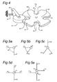
- Fig. 4 shows a disc-shaped body 24, having a bearing surface 26 situated substantially parallel to the running surfaces.
- the disc-shaped body comprises at least two cavities 29, following one behind the other in the peripheral direction 28.
- the disc-shaped body comprises four cavities 29, 29', 29", 29"'. The cavities serve for the stable and supportive reception of the unsupported wheel of the carrier as the carrier is transported on the transport mechanism from a take-up position RC to a delivery position RL.
- the disc-shaped body shown in Fig. 4 comprises four locking slots 30, which cooperate with a spring-loaded stop member 31 which is fixedly arranged with respect to the pivot axle 19.
- the stop member 31 ensures that the disc-shaped body 24 can undergo no unwanted rotations.
- the disc-shaped body if not in use, will hence always be in a receptive position for the take-up, transportation and, subsequently, delivery of the carrier. It is possible to provide the disc-shaped body 24 with more or fewer locking slots.
- the disc-shaped body 24 is provided with at least two locking slots 30.
- the locking slots 30 can also be realized in such a way that they additionally serve for the guidance and take-up of a bearing axle 7 of a carrier 6 according to Fig. 2 , for the purpose of making the transport mechanism 12 engage with the carrier in a load-bearing manner.
- the carrier 6, in an embodiment as shown in Fig. 2 is displaceable along a first track 3 of the device 1.
- the carrier here runs with a first wheel 13 over a first running surface 5 and with a second wheel 14 over a second running surface 8.
- the second wheel 14 of the carrier will be lifted from the second running surface 8 and will land on a cavity 29 of the disc-shaped body 24 of the transport mechanism 12.
- the transport mechanism will now engage with the carrier in a load-bearing manner.
- the spring-loaded stop member 31 which cooperates with the locking slots 30 of the disc-shaped body 24, the latter will encounter some rotational resistance.
- the user then notices that the carrier 6 is at or close to the junction 9, whereafter the user has the option of making the carrier 6 undergo a change of direction.
- the user has the option of moving the carrier further along the first track 3.
- the user has the option of moving the carrier to the second track 4.
- the user has subsequently to move the carrier onward in the desired direction.
- the disc-shaped body 24 will here rotate over a predetermined angular distance, after which the transport mechanism 12 finds itself in a delivery position.
- the transport mechanism is provided with a stop member 31, this in the delivery position will re-engage with a locking slot 30.
- the user then knows that the disc-shaped body 24 is back in a delivery position.
- the user can then move the carrier onward in the desired direction.
- the user may decide to reuse the transport mechanism 12 to displace the carrier in another direction or into another track.
- FIGs. 5a-c,e Possible embodiments of the junction 9 in which the transport mechanism 12 is usable are shown in Figs. 5a-c,e .
- Fig. 5a shows a junction 9, which is provided with a first rail 41 and a second rail 42.
- the two rails make an angle of 90° to each other.
- the rails each comprise a guide having running surfaces over which a carrier is movable.
- the transport mechanism ensures that the carrier is easily movable through the right angle.
- Fig. 5b shows an embodiment as in Fig. 5a , only that the two rails now make an angle to each other which is equal to ⁇ .
- the device can additionally be provided with three rails 51,52,53, the rails mutually possessing an equal angular spacing, as shown in Fig. 5c . It is further possible to vary the angles one to another.
- the junction is here provided with four rails 61, 62, 63, 64, which form a crossing.
- a transport mechanism 12 which is not a part of the invention.
- the carrier can here be placed from a first branch onwards on the transport mechanism. The user can subsequently move the carrier rotatably in the direction of the different delivery positions.
- the transport mechanism can here act as a carrousel. Once the carrier has the desired position, the user can move the carrier onward in the desired direction.
- junctions are, of course, conceivable. For instance, it is possible to use more than four rails, or place different transport mechanisms relatively close together, in order to obtain a desired junction.
- a transport mechanism 12 which is not a part of the invention, having a first track 74 and a second track 71 is connected to a transport mechanism 12' having a first track 73 and a second track 72.
- the carrier can then be moved from the first transport mechanism 12 to the second transport mechanism 12'. In this way, a crossing having four tracks is feasible.
Landscapes
- Engineering & Computer Science (AREA)
- Mechanical Engineering (AREA)
- Handcart (AREA)
- Conveying And Assembling Of Building Elements In Situ (AREA)
Claims (5)
- Dispositif (1) comprenant un système de rails et au moins un support (6), dans lequel le système de rails comprend un premier guide (2) ayant une première paire de surfaces de roulement sensiblement parallèles (5, 8), qui sont placées le long d'une première voie (3) à une distance latérale et verticale, et un deuxième guide (2) ayant une deuxième paire de surfaces de roulement sensiblement parallèles (5, 8), qui sont placées le long d'une deuxième voie (4) à une distance latérale et verticale, où les surfaces de roulement (5, 8) sont reliées aux parois latérales (20, 20') s'étendant transversalement sur les surfaces de roulement (5, 8), où la deuxième paire de surfaces de roulement, au niveau d'une jonction (9), s'étend à un angle vers la première paire de surfaces de roulement et croise la première paire de surfaces de roulement à la même hauteur, où le support (6) peut se déplacer sur les surfaces de roulement, où le support (6) est situé entre les parois latérales (20, 20') et comprend un axe porteur (7), s'étendant perpendiculairement aux surfaces de roulement (5, 8), pour la fixation d'une charge, ledit axe porteur s'étend entre les surfaces de roulement (5, 8), le support comprenant deux roues biseautées (13, 14) séparées d'une distance verticale, les deux nous biseautées peuvent tourner autour d'un axe de roue (17) situé perpendiculairement aux surfaces de roulement et coaxialement audit axe porteur (7), lesdites roues s'engagent avec les surfaces de roulement respectives, caractérisé en ce que le dispositif comprend un mécanisme de transport (12) comportant un corps en forme de disque (24), qui peut pivoter autour d'un axe de pivotement (19) qui s'étendant perpendiculairement aux surfaces de roulement (5, 8), lequel axe de pivotement (19) est monté à proximité de la jonction (9) le long d'un côté extérieur des parois latérales, les parois latérales, à proximité de l'axe de pivotement, sont pourvues de fentes (22) à travers lesquelles le corps en forme de disque (24) atteint le niveau entre les parois latérales (20, 20'), le corps en forme de disque (24) présente une surface porteuse (26) située de manière sensiblement parallèle aux surfaces de roulement et pourvue d'au moins deux cavités (29, 29', 29", 29"'), qui se suivent dans la direction périphérique, pour une réception de soutien d'une roue non soutenue du support, le corps en forme de disque (24) peut pivoter entre une position de prise (RC) dans la première voie (3), pour un engagement porteur de charge avec le support (6), et une position de distribution (RL) dans la deuxième voie (4) pour la libération du support.
- Dispositif selon la revendication 1, dans lequel le corps en forme de disque (24) est pourvu, le long de la périphérie, d'au moins deux fentes de verrouillage (30), qui coopèrent avec un élément d'arrêt (31), agencé de manière fixe par rapport à l'axe de pivotement (19), pour fixer le corps en forme de disque dans une position angulaire prédéterminée.
- Dispositif (1) selon la revendication 1 ou 2, dans lequel, dans une position de port de charge du mécanisme de transport, la roue biseautée supérieure (14) s'engage avec le mécanisme de transport.
- Dispositif selon l'une quelconque des revendications précédentes, dans lequel au moins deux supports sont prévus pour la fixation d'au moins deux charges, dans lequel l'au moins deux charges sont mobiles de manière indépendante.
- Dispositif selon l'une quelconque des revendications précédentes, dans lequel au moins deux supports sont prévus pour la fixation d'une seule charge à aux dits supports, au moins un des deux supports étant espacé dans une direction longitudinale du guide, et/ou dans lequel la charge est un panneau mural.
Applications Claiming Priority (1)
| Application Number | Priority Date | Filing Date | Title |
|---|---|---|---|
| NL2001337A NL2001337C2 (nl) | 2008-02-29 | 2008-02-29 | Inrichting voorzien van een geleider, railsysteem en transportinrichting voor toepassing in een dergelijke inrichting. |
Publications (2)
| Publication Number | Publication Date |
|---|---|
| EP2096246A1 EP2096246A1 (fr) | 2009-09-02 |
| EP2096246B1 true EP2096246B1 (fr) | 2014-09-03 |
Family
ID=39776974
Family Applications (1)
| Application Number | Title | Priority Date | Filing Date |
|---|---|---|---|
| EP09153572.4A Not-in-force EP2096246B1 (fr) | 2008-02-29 | 2009-02-25 | Dispositif avec un système de rails, au moins un support et un méchanisme de transport pour un tel dispositif |
Country Status (4)
| Country | Link |
|---|---|
| US (1) | US8256062B2 (fr) |
| EP (1) | EP2096246B1 (fr) |
| HK (1) | HK1134332A1 (fr) |
| NL (1) | NL2001337C2 (fr) |
Families Citing this family (7)
| Publication number | Priority date | Publication date | Assignee | Title |
|---|---|---|---|---|
| NL2004223C2 (nl) | 2010-02-11 | 2011-08-15 | Espero Bv | Railsysteem, alsmede inrichting omvattende een dergelijk railsysteem en een verplaatsbare drager. |
| US8505163B2 (en) * | 2010-12-09 | 2013-08-13 | Ruei-Hsing Lin | Hook device for stretching curtain on rack assembly |
| US8573418B2 (en) * | 2010-12-09 | 2013-11-05 | Ruei-Hsing Lin | Rack assembly for displaying curtain |
| CN107323361B (zh) * | 2016-04-28 | 2022-06-17 | 福特环球技术公司 | 储物总成 |
| US10077588B1 (en) | 2017-06-16 | 2018-09-18 | Gregory A Header | Path guide for movable partition assemblies |
| JP6481174B2 (ja) * | 2017-07-12 | 2019-03-13 | 岡田装飾金物株式会社 | レール、ランナー、並びにレールとランナーとのセット |
| AU2021277452A1 (en) | 2020-05-22 | 2022-11-10 | Novelquip Forestry (Pty) Ltd | Planting apparatus |
Family Cites Families (6)
| Publication number | Priority date | Publication date | Assignee | Title |
|---|---|---|---|---|
| DE2046429C3 (de) * | 1970-09-21 | 1976-01-02 | Fa. Justin Hueppe, 2900 Oldenburg | Drehscheiben-Kreuzung für einen Knotenpunkt eines Laufschienen-Systems |
| US3708916A (en) * | 1971-04-23 | 1973-01-09 | American Standard Inc | Movable wall panel systems |
| GB2102867B (en) * | 1980-12-08 | 1985-03-06 | Itoki Kosakusho | An apparatus for guiding movable suspended partition walls |
| DE3147273A1 (de) * | 1981-11-28 | 1983-07-28 | Justin Hüppe GmbH, 2900 Oldenburg | Raumtrennwand |
| CA2032210C (fr) * | 1989-12-26 | 1999-09-07 | Charles E. Williams | Transporteur multi-directionnel |
| JP2773724B2 (ja) * | 1996-01-04 | 1998-07-09 | コクヨ株式会社 | 移動間仕切装置 |
-
2008
- 2008-02-29 NL NL2001337A patent/NL2001337C2/nl not_active IP Right Cessation
-
2009
- 2009-02-25 EP EP09153572.4A patent/EP2096246B1/fr not_active Not-in-force
- 2009-02-27 US US12/394,696 patent/US8256062B2/en not_active Expired - Fee Related
-
2010
- 2010-03-02 HK HK10102260.7A patent/HK1134332A1/xx not_active IP Right Cessation
Also Published As
| Publication number | Publication date |
|---|---|
| EP2096246A1 (fr) | 2009-09-02 |
| US8256062B2 (en) | 2012-09-04 |
| US20090217839A1 (en) | 2009-09-03 |
| HK1134332A1 (en) | 2010-04-23 |
| NL2001337C2 (nl) | 2009-09-01 |
Similar Documents
| Publication | Publication Date | Title |
|---|---|---|
| EP2096246B1 (fr) | Dispositif avec un système de rails, au moins un support et un méchanisme de transport pour un tel dispositif | |
| CA2019235C (fr) | Supports a galets orientables et rail pour murs escamotables | |
| US4752987A (en) | Support and guide system for movable door or wall elements | |
| US7658273B2 (en) | Carriage-type conveyance device | |
| JPH0559007B2 (fr) | ||
| CA1277943C (fr) | Methode et dispositif transfert pour l'assemblage d'automobiles | |
| EP3003917B1 (fr) | Navette d'entrepôt automatisé | |
| US4416202A (en) | Conveyor bench/work station with shunt | |
| JPS6253673B2 (fr) | ||
| CN112041521A (zh) | 停车设备用车辆左右对齐装置 | |
| EP2418137A1 (fr) | Chariot de transport pour installations industrielles | |
| EP3208168B1 (fr) | Ensemble de palier, agencement de faisceaux destiné à changer la direction d'un chariot avec l'ensemble de palier et système de changement de rail avec ledit ensemble de palier et agencement de faisceaux | |
| US10348066B2 (en) | Automatic circuit breaker pan interlock | |
| AU2003204962B2 (en) | Multi-program trolleys and switches | |
| US4532385A (en) | Load transporting device and electric supply track therefor | |
| US3405795A (en) | Apparatus for stowing and conveying articles | |
| EP2360335B1 (fr) | Système de rails et ensemble comprenant un tel système de rails et un support mobile | |
| CA2174597A1 (fr) | Systeme d'entreposage de produits plans | |
| WO2006062414A1 (fr) | Pont roulant | |
| EP3480358B1 (fr) | Système d'aiguillage pour systèmes de transport de véhicule sur rails | |
| CA2390218C (fr) | Systeme de commutation automatique de piste pour des parois pouvant etre actionnees | |
| RU2787735C2 (ru) | Набор рельсовых колес и тележка | |
| EP2305535B1 (fr) | Chariot | |
| CN112437727B (zh) | 轨道轮组和移动车辆 | |
| FR2472056A1 (fr) | Croisement de voies pour chemin de fer suspendu a deux voies |
Legal Events
| Date | Code | Title | Description |
|---|---|---|---|
| PUAI | Public reference made under article 153(3) epc to a published international application that has entered the european phase |
Free format text: ORIGINAL CODE: 0009012 |
|
| AK | Designated contracting states |
Kind code of ref document: A1 Designated state(s): AT BE BG CH CY CZ DE DK EE ES FI FR GB GR HR HU IE IS IT LI LT LU LV MC MK MT NL NO PL PT RO SE SI SK TR |
|
| AX | Request for extension of the european patent |
Extension state: AL BA RS |
|
| 17P | Request for examination filed |
Effective date: 20100302 |
|
| REG | Reference to a national code |
Ref country code: HK Ref legal event code: DE Ref document number: 1134332 Country of ref document: HK |
|
| AKX | Designation fees paid |
Designated state(s): AT BE BG CH CY CZ DE DK EE ES FI FR GB GR HR HU IE IS IT LI LT LU LV MC MK MT NL NO PL PT RO SE SI SK TR |
|
| 17Q | First examination report despatched |
Effective date: 20100820 |
|
| 17Q | First examination report despatched |
Effective date: 20100916 |
|
| GRAP | Despatch of communication of intention to grant a patent |
Free format text: ORIGINAL CODE: EPIDOSNIGR1 |
|
| INTG | Intention to grant announced |
Effective date: 20140325 |
|
| GRAS | Grant fee paid |
Free format text: ORIGINAL CODE: EPIDOSNIGR3 |
|
| GRAA | (expected) grant |
Free format text: ORIGINAL CODE: 0009210 |
|
| AK | Designated contracting states |
Kind code of ref document: B1 Designated state(s): AT BE BG CH CY CZ DE DK EE ES FI FR GB GR HR HU IE IS IT LI LT LU LV MC MK MT NL NO PL PT RO SE SI SK TR |
|
| REG | Reference to a national code |
Ref country code: GB Ref legal event code: FG4D |
|
| REG | Reference to a national code |
Ref country code: AT Ref legal event code: REF Ref document number: 685732 Country of ref document: AT Kind code of ref document: T Effective date: 20140915 Ref country code: CH Ref legal event code: EP |
|
| REG | Reference to a national code |
Ref country code: IE Ref legal event code: FG4D |
|
| REG | Reference to a national code |
Ref country code: DE Ref legal event code: R096 Ref document number: 602009026381 Country of ref document: DE Effective date: 20141016 |
|
| REG | Reference to a national code |
Ref country code: NL Ref legal event code: T3 |
|
| REG | Reference to a national code |
Ref country code: AT Ref legal event code: MK05 Ref document number: 685732 Country of ref document: AT Kind code of ref document: T Effective date: 20140903 |
|
| PG25 | Lapsed in a contracting state [announced via postgrant information from national office to epo] |
Ref country code: ES Free format text: LAPSE BECAUSE OF FAILURE TO SUBMIT A TRANSLATION OF THE DESCRIPTION OR TO PAY THE FEE WITHIN THE PRESCRIBED TIME-LIMIT Effective date: 20140903 Ref country code: GR Free format text: LAPSE BECAUSE OF FAILURE TO SUBMIT A TRANSLATION OF THE DESCRIPTION OR TO PAY THE FEE WITHIN THE PRESCRIBED TIME-LIMIT Effective date: 20141204 Ref country code: NO Free format text: LAPSE BECAUSE OF FAILURE TO SUBMIT A TRANSLATION OF THE DESCRIPTION OR TO PAY THE FEE WITHIN THE PRESCRIBED TIME-LIMIT Effective date: 20141203 Ref country code: SE Free format text: LAPSE BECAUSE OF FAILURE TO SUBMIT A TRANSLATION OF THE DESCRIPTION OR TO PAY THE FEE WITHIN THE PRESCRIBED TIME-LIMIT Effective date: 20140903 Ref country code: FI Free format text: LAPSE BECAUSE OF FAILURE TO SUBMIT A TRANSLATION OF THE DESCRIPTION OR TO PAY THE FEE WITHIN THE PRESCRIBED TIME-LIMIT Effective date: 20140903 Ref country code: LT Free format text: LAPSE BECAUSE OF FAILURE TO SUBMIT A TRANSLATION OF THE DESCRIPTION OR TO PAY THE FEE WITHIN THE PRESCRIBED TIME-LIMIT Effective date: 20140903 |
|
| REG | Reference to a national code |
Ref country code: HK Ref legal event code: GR Ref document number: 1134332 Country of ref document: HK |
|
| REG | Reference to a national code |
Ref country code: LT Ref legal event code: MG4D |
|
| PG25 | Lapsed in a contracting state [announced via postgrant information from national office to epo] |
Ref country code: AT Free format text: LAPSE BECAUSE OF FAILURE TO SUBMIT A TRANSLATION OF THE DESCRIPTION OR TO PAY THE FEE WITHIN THE PRESCRIBED TIME-LIMIT Effective date: 20140903 Ref country code: HR Free format text: LAPSE BECAUSE OF FAILURE TO SUBMIT A TRANSLATION OF THE DESCRIPTION OR TO PAY THE FEE WITHIN THE PRESCRIBED TIME-LIMIT Effective date: 20140903 Ref country code: LV Free format text: LAPSE BECAUSE OF FAILURE TO SUBMIT A TRANSLATION OF THE DESCRIPTION OR TO PAY THE FEE WITHIN THE PRESCRIBED TIME-LIMIT Effective date: 20140903 Ref country code: CY Free format text: LAPSE BECAUSE OF FAILURE TO SUBMIT A TRANSLATION OF THE DESCRIPTION OR TO PAY THE FEE WITHIN THE PRESCRIBED TIME-LIMIT Effective date: 20140903 |
|
| PG25 | Lapsed in a contracting state [announced via postgrant information from national office to epo] |
Ref country code: EE Free format text: LAPSE BECAUSE OF FAILURE TO SUBMIT A TRANSLATION OF THE DESCRIPTION OR TO PAY THE FEE WITHIN THE PRESCRIBED TIME-LIMIT Effective date: 20140903 Ref country code: SK Free format text: LAPSE BECAUSE OF FAILURE TO SUBMIT A TRANSLATION OF THE DESCRIPTION OR TO PAY THE FEE WITHIN THE PRESCRIBED TIME-LIMIT Effective date: 20140903 Ref country code: RO Free format text: LAPSE BECAUSE OF FAILURE TO SUBMIT A TRANSLATION OF THE DESCRIPTION OR TO PAY THE FEE WITHIN THE PRESCRIBED TIME-LIMIT Effective date: 20140903 Ref country code: IS Free format text: LAPSE BECAUSE OF FAILURE TO SUBMIT A TRANSLATION OF THE DESCRIPTION OR TO PAY THE FEE WITHIN THE PRESCRIBED TIME-LIMIT Effective date: 20150103 Ref country code: PT Free format text: LAPSE BECAUSE OF FAILURE TO SUBMIT A TRANSLATION OF THE DESCRIPTION OR TO PAY THE FEE WITHIN THE PRESCRIBED TIME-LIMIT Effective date: 20150105 Ref country code: CZ Free format text: LAPSE BECAUSE OF FAILURE TO SUBMIT A TRANSLATION OF THE DESCRIPTION OR TO PAY THE FEE WITHIN THE PRESCRIBED TIME-LIMIT Effective date: 20140903 |
|
| PG25 | Lapsed in a contracting state [announced via postgrant information from national office to epo] |
Ref country code: PL Free format text: LAPSE BECAUSE OF FAILURE TO SUBMIT A TRANSLATION OF THE DESCRIPTION OR TO PAY THE FEE WITHIN THE PRESCRIBED TIME-LIMIT Effective date: 20140903 |
|
| REG | Reference to a national code |
Ref country code: DE Ref legal event code: R097 Ref document number: 602009026381 Country of ref document: DE |
|
| PG25 | Lapsed in a contracting state [announced via postgrant information from national office to epo] |
Ref country code: BE Free format text: LAPSE BECAUSE OF NON-PAYMENT OF DUE FEES Effective date: 20150228 |
|
| PLBE | No opposition filed within time limit |
Free format text: ORIGINAL CODE: 0009261 |
|
| STAA | Information on the status of an ep patent application or granted ep patent |
Free format text: STATUS: NO OPPOSITION FILED WITHIN TIME LIMIT |
|
| PG25 | Lapsed in a contracting state [announced via postgrant information from national office to epo] |
Ref country code: DK Free format text: LAPSE BECAUSE OF FAILURE TO SUBMIT A TRANSLATION OF THE DESCRIPTION OR TO PAY THE FEE WITHIN THE PRESCRIBED TIME-LIMIT Effective date: 20140903 |
|
| 26N | No opposition filed |
Effective date: 20150604 |
|
| PG25 | Lapsed in a contracting state [announced via postgrant information from national office to epo] |
Ref country code: IT Free format text: LAPSE BECAUSE OF FAILURE TO SUBMIT A TRANSLATION OF THE DESCRIPTION OR TO PAY THE FEE WITHIN THE PRESCRIBED TIME-LIMIT Effective date: 20140903 |
|
| REG | Reference to a national code |
Ref country code: CH Ref legal event code: PL |
|
| PG25 | Lapsed in a contracting state [announced via postgrant information from national office to epo] |
Ref country code: CH Free format text: LAPSE BECAUSE OF NON-PAYMENT OF DUE FEES Effective date: 20150228 Ref country code: LI Free format text: LAPSE BECAUSE OF NON-PAYMENT OF DUE FEES Effective date: 20150228 Ref country code: MC Free format text: LAPSE BECAUSE OF FAILURE TO SUBMIT A TRANSLATION OF THE DESCRIPTION OR TO PAY THE FEE WITHIN THE PRESCRIBED TIME-LIMIT Effective date: 20140903 |
|
| PG25 | Lapsed in a contracting state [announced via postgrant information from national office to epo] |
Ref country code: SI Free format text: LAPSE BECAUSE OF FAILURE TO SUBMIT A TRANSLATION OF THE DESCRIPTION OR TO PAY THE FEE WITHIN THE PRESCRIBED TIME-LIMIT Effective date: 20140903 |
|
| REG | Reference to a national code |
Ref country code: FR Ref legal event code: PLFP Year of fee payment: 8 |
|
| PG25 | Lapsed in a contracting state [announced via postgrant information from national office to epo] |
Ref country code: BE Free format text: LAPSE BECAUSE OF FAILURE TO SUBMIT A TRANSLATION OF THE DESCRIPTION OR TO PAY THE FEE WITHIN THE PRESCRIBED TIME-LIMIT Effective date: 20140903 |
|
| PG25 | Lapsed in a contracting state [announced via postgrant information from national office to epo] |
Ref country code: MT Free format text: LAPSE BECAUSE OF FAILURE TO SUBMIT A TRANSLATION OF THE DESCRIPTION OR TO PAY THE FEE WITHIN THE PRESCRIBED TIME-LIMIT Effective date: 20140903 |
|
| REG | Reference to a national code |
Ref country code: FR Ref legal event code: PLFP Year of fee payment: 9 |
|
| PG25 | Lapsed in a contracting state [announced via postgrant information from national office to epo] |
Ref country code: BG Free format text: LAPSE BECAUSE OF FAILURE TO SUBMIT A TRANSLATION OF THE DESCRIPTION OR TO PAY THE FEE WITHIN THE PRESCRIBED TIME-LIMIT Effective date: 20140903 Ref country code: HU Free format text: LAPSE BECAUSE OF FAILURE TO SUBMIT A TRANSLATION OF THE DESCRIPTION OR TO PAY THE FEE WITHIN THE PRESCRIBED TIME-LIMIT; INVALID AB INITIO Effective date: 20090225 |
|
| PGFP | Annual fee paid to national office [announced via postgrant information from national office to epo] |
Ref country code: IE Payment date: 20170224 Year of fee payment: 9 Ref country code: LU Payment date: 20170224 Year of fee payment: 9 |
|
| PGFP | Annual fee paid to national office [announced via postgrant information from national office to epo] |
Ref country code: TR Payment date: 20170220 Year of fee payment: 9 |
|
| PGFP | Annual fee paid to national office [announced via postgrant information from national office to epo] |
Ref country code: NL Payment date: 20171221 Year of fee payment: 10 |
|
| REG | Reference to a national code |
Ref country code: FR Ref legal event code: PLFP Year of fee payment: 10 |
|
| PGFP | Annual fee paid to national office [announced via postgrant information from national office to epo] |
Ref country code: GB Payment date: 20180227 Year of fee payment: 10 |
|
| PGFP | Annual fee paid to national office [announced via postgrant information from national office to epo] |
Ref country code: FR Payment date: 20180226 Year of fee payment: 10 |
|
| PG25 | Lapsed in a contracting state [announced via postgrant information from national office to epo] |
Ref country code: MK Free format text: LAPSE BECAUSE OF FAILURE TO SUBMIT A TRANSLATION OF THE DESCRIPTION OR TO PAY THE FEE WITHIN THE PRESCRIBED TIME-LIMIT Effective date: 20140903 |
|
| PGFP | Annual fee paid to national office [announced via postgrant information from national office to epo] |
Ref country code: DE Payment date: 20180430 Year of fee payment: 10 |
|
| REG | Reference to a national code |
Ref country code: IE Ref legal event code: MM4A |
|
| PG25 | Lapsed in a contracting state [announced via postgrant information from national office to epo] |
Ref country code: LU Free format text: LAPSE BECAUSE OF NON-PAYMENT OF DUE FEES Effective date: 20180225 |
|
| PG25 | Lapsed in a contracting state [announced via postgrant information from national office to epo] |
Ref country code: IE Free format text: LAPSE BECAUSE OF NON-PAYMENT OF DUE FEES Effective date: 20180225 |
|
| REG | Reference to a national code |
Ref country code: DE Ref legal event code: R119 Ref document number: 602009026381 Country of ref document: DE |
|
| REG | Reference to a national code |
Ref country code: NL Ref legal event code: MM Effective date: 20190301 |
|
| GBPC | Gb: european patent ceased through non-payment of renewal fee |
Effective date: 20190225 |
|
| PG25 | Lapsed in a contracting state [announced via postgrant information from national office to epo] |
Ref country code: GB Free format text: LAPSE BECAUSE OF NON-PAYMENT OF DUE FEES Effective date: 20190225 Ref country code: NL Free format text: LAPSE BECAUSE OF NON-PAYMENT OF DUE FEES Effective date: 20190301 Ref country code: DE Free format text: LAPSE BECAUSE OF NON-PAYMENT OF DUE FEES Effective date: 20190903 |
|
| PG25 | Lapsed in a contracting state [announced via postgrant information from national office to epo] |
Ref country code: FR Free format text: LAPSE BECAUSE OF NON-PAYMENT OF DUE FEES Effective date: 20190228 |
|
| PG25 | Lapsed in a contracting state [announced via postgrant information from national office to epo] |
Ref country code: TR Free format text: LAPSE BECAUSE OF NON-PAYMENT OF DUE FEES Effective date: 20180225 |