EP2094597B1 - Garde-pieds destiné à une cabine d'ascenseur - Google Patents
Garde-pieds destiné à une cabine d'ascenseur Download PDFInfo
- Publication number
- EP2094597B1 EP2094597B1 EP07858303.6A EP07858303A EP2094597B1 EP 2094597 B1 EP2094597 B1 EP 2094597B1 EP 07858303 A EP07858303 A EP 07858303A EP 2094597 B1 EP2094597 B1 EP 2094597B1
- Authority
- EP
- European Patent Office
- Prior art keywords
- toe guard
- panel part
- panel
- edge
- car
- Prior art date
- Legal status (The legal status is an assumption and is not a legal conclusion. Google has not performed a legal analysis and makes no representation as to the accuracy of the status listed.)
- Not-in-force
Links
Images


Classifications
-
- B—PERFORMING OPERATIONS; TRANSPORTING
- B66—HOISTING; LIFTING; HAULING
- B66B—ELEVATORS; ESCALATORS OR MOVING WALKWAYS
- B66B13/00—Doors, gates, or other apparatus controlling access to, or exit from, cages or lift well landings
- B66B13/24—Safety devices in passenger lifts, not otherwise provided for, for preventing trapping of passengers
- B66B13/28—Safety devices in passenger lifts, not otherwise provided for, for preventing trapping of passengers between car or cage and wells
- B66B13/285—Toe guards or apron devices
Definitions
- the present invention relates to a toe guard as defined in the preamble of claim 1.
- a toe guard (also called foot guard) is a safety device which is comprised in an elevator car and forms a wall extending downwards from the elevator car.
- the toe guard is intended to cover this gap and thus to prevent a person escaping from the car onto the landing floor from falling into the shaft and/or to prevent any body part of the passenger from getting between the car and the landing floor.
- a toe guard suited for a small shaft bottom space is in itself very advantageous as it permits of a very low shaft bottom space.
- Shaft bottom space refers to the space remaining below an elevator car at the lowest stopping level.
- specification EP 1 215 159 A2 discloses a toe guard for an elevator car, said toe guard comprising a movable panel provided with a locking device, and guide tracks mounted below the car in a substantially horizontal orientation.
- the panel being guided and supported by the guide tracks, can be moved between a stowaway position and an operative position.
- the panel rests on the guide tracks in a substantially horizontal orientation, stowed away below the elevator car, where it can be locked in place by means of the locking device.
- the toe guard supported by the guide tracks, is drawn out onto the landing floor and tilted to cover the gap between the car sill and the landing floor.
- the toe guard In the operative position, the toe guard can be locked to the landing door jambs by means of the locking device, ensuring that the toe guard will not bend e.g. in consequence of a kick or other external exertion of force.
- the EP specification in question discloses a one-piece plate-like panel.
- a problem with the above-mentioned prior-art bendable toe guard formed from a single panel part is that the panel in its operative position always has the same length and it can only be used to cover a gap of a certain size exposing the shaft between an elevator car and a landing floor, in a situation where the elevator car has stopped at a level between floors.
- telescoping toe guards consisting of two or more parts for small shaft bottom spaces are disclosed e.g. in specifications WO2005/121015 and FR2841886 , but a typical feature of these toe guards is that they work on the shaft side and do not extend onto the landing floor and are not designed to be locked to the landing door jambs.
- the object of the invention is to overcome the above-mentioned drawbacks.
- a specific object of the invention is to disclose an improved toe guard whose length is variable according to need.
- the toe guard of the invention is characterized by what is disclosed in the characterizing part of claim 1.
- Other embodiments of the invention are characterized by what is disclosed in the other claims.
- Inventive embodiments are also presented in the description part and drawings of the present application.
- the inventive content disclosed in the application can also be defined in other ways than is done in the claims below.
- the inventive content may also consist of several separate inventions, especially if the invention is considered in the light of explicit or implicit sub-tasks or with respect to advantages or sets of advantages achieved. In this case, some of the attributes contained in the claims below may be superfluous from the point of view of separate inventive concepts.
- the features of different embodiments of the invention can be applied in connection with other embodiments within the scope of the basic inventive concept.
- the panel forming the toe guard comprises a first panel part, which, guided by guide tracks, is movable substantially between a position where it is drawn out onto a landing floor and a position where it is stowed away under the car, and a second panel part which, guided by the first panel part, is telescopically movable between a retracted extreme position where the first and second panel parts are disposed in a mutually nested and/or superposed relationship and an extended extreme position where the first and second panel parts are disposed substantially in a mutually adjacent relationship.
- the toe guard When the toe guard is being moved from the stowaway position into the operative position, it assumes steplessly a suitable length between the aforesaid retracted extreme position and the aforesaid extended extreme position, depending in each case on the height position of the elevator car having stopped between floors relative to the landing floor level.
- the toe guard has been adapted to allow its use when the distance between the car and the landing floor is of the order of about 50 mm at a minimum and about 1 m at a maximum.
- the elevator comprises a safety circuit that prevents the elevator from moving in an error situation.
- the toe guard comprises a sensor connected to the safety circuit. The sensor is arranged to detect an error situation where the toe guard is not in the stowaway position.
- Safety circuit refers to a control circuit or a part of it that contains safety connections and contacts in series with the control coils of those contactors the opening of whose contacts causes the elevator to stop.
- the second panel part has a first side edge and a second side edge extending parallel to the guide tracks.
- the locking device comprises a first locking bolt, which is arranged to be movable between a locking position, in which the bolt projects from the first side edge in a substantially perpendicular direction, and a releasing position with the bolt retracted into/onto/under the second panel part.
- a second locking bolt is arranged to be movable between a locking position, in which the bolt projects from the second side edge in a substantially perpendicular direction, and a releasing position with the bolt retracted into/onto/under the second panel part.
- the locking device comprises an actuating mechanism for moving the first locking bolt and the second locking bolt simultaneously between the locking position and the releasing position.
- the second panel part has a forward edge, which is the edge oriented towards the landing.
- the actuating mechanism comprises an axle pin which is mounted on the second panel part near its forward edge so as to be rotatable about an axis perpendicular to the plane of the second panel part, said axle pin comprising an engaging element whereby the axle pin can be gripped with a tool to rotate it.
- a turnplate is attached to the axle pin so as to be rotatable together with it.
- a first rod, at the first end of which is the first locking bolt is pivotally joined at its second end to the turnplate at a distance from the axle pin.
- a second rod, at the first end of which is the second locking bolt is pivotally joined at its second end to the turnplate at a distance from the axle pin on the opposite side relative to the pivotal joint of the second end of the first rod.
- the engaging element is a triangular notch adapted to be gripped with a triangular key.
- the actuating mechanism comprises a spring arranged to force the locking bolts towards the releasing position.
- the axle pin is disposed in about the middle region of the second panel part in the immediate vicinity of the forward edge.
- the first panel part comprises a rear edge, a third side edge with a pin fastened to it at a position near the rear edge, and a fourth side edge with a pin fastened to it at a position near the rear edge.
- the toe guard is arranged to be supported by a pair of supporting members, each one of which has a horizontal slot through which the pin is adapted to extend. These slots form the aforesaid guide tracks.
- the slot 31 has at its end near the car door sill a downward part, into which the pin falls when the first panel part is in the extended extreme position and which part together with the pin constitutes a hinge about which the toe guard is turnable into an angle relative to the horizontal.
- the first panel part is formed from sheet metal having a first edge bend at either side edge.
- the second panel part is formed from sheet metal having a second edge bend at either side edge, the second panel part being adapted to fit with a clearance in the space delimited by the first edge bends.
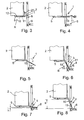
- Figs. 1 - 6 show an elevator with its car 2 stuck between floors at distance h from a landing.
- the car 2 is provided with horizontal guide tracks 5 secured under the floor of the car and a toe guard 1 is mounted to be supported by the guide tracks 5.
- the toe guard is in a stowaway position A under the floor, in an orientation parallel to the guide tracks 5, so it takes up only a small space in the vertical direction.
- the toe guard 1 comprises a movable panel 3, which consists of two panel parts telescopically connected together, i.e. a first panel part 10 and a second panel part 11.
- the panel Being guided and supported by the guide tracks 5, the panel is movable between a stowaway position A and an operative position B, which are shown in Figs. 1 and 3 .
- the panel parts 10 and 11 rest on the guide tracks in a substantially horizontal orientation under the car, where they can be locked in place by means of a locking device 4.
- the toe guard 1, supported by the guide tracks 5 has been drawn out onto the landing floor 6 and tilted to cover the gap 8 between the car sill 7 and the landing floor 6.
- the toe guard 1 can be locked to the door jambs 9 of the landing door by means of the locking device 4.
- the first panel part 10 can be moved along the guide tracks 5 between a drawn-out position, in which it is drawn out substantially onto the landing floor 6, and a stowed-away position under the car 2.
- the second panel part 11, being guided by the first panel part 10, is telescopically movable between a retracted extreme position and an extended extreme position.
- the first and second panel parts are disposed in a mutually nested and/or superposed relationship ( Fig. 3 ).
- the first and second panel parts are disposed substantially in a mutually adjacent relationship (see Figs. 2 , 6 , 10 ).
- the toe guard When the toe guard is moved from the stowaway position into the operative position, it assumes steplessly a suitable length between the aforesaid retracted extreme position and the aforesaid extended extreme position, depending in each case on the height position h of the elevator car having stopped between floors relative to the landing floor 6, as is also visualized in Figs. 7 and 8 .
- the toe guard 1 has been adapted to permit its use when the distance h between the car 2 and the landing floor 6 is of the order of about 50 mm at a minimum and about 1 m at a maximum.
- the toe guard 1 is only used when the car remains at a maximum distance of 800 mm above the landing floor. If the car is at a distance exceeding 800 mm above the landing floor, then the car must first be lowered to the level of the landing floor before the passengers are allowed to get out of the car.
- the elevator comprises a safety circuit which prevents elevator movement in an error situation.
- the toe guard 1 comprises a sensor 12 connected to the safety circuit.
- the sensor has been arranged to detect an error situation where the toe guard 1 is not in the stowaway position A.
- the sensor 12 may be e.g. a limit switch which is turned on by the panel parts 10, 11 when locked in the stowaway position shown in Fig. 3 .
- the toe guard 1 is used as illustrated in Figs. 3 and 6 , by releasing the locking device 4 by means of a tool 21.
- the panel parts 10 and 11 are pulled horizontally along the guide tracks 5 onto the landing floor 6.
- the panel parts 10 and 11 are tilted and the second panel part 11 is locked by means of the locking device 4 to the landing door jambs 9.
- the locking device 4 comprises a first locking bolt 15, which is arranged to be movable between a locking position with the bolt projecting from the first side edge 13 of the second panel part 11 in a substantially perpendicular direction and a releasing position with the bolt retracted into/onto/under the second panel part 11.
- the locking device 4 further comprises a second locking bolt 16, which is arranged to be movable between a locking position with the bolt projecting from the second side edge 14 of the second panel part 11 in a substantially perpendicular direction and a releasing position with the bolt retracted into/onto/under the second panel part 11.
- the actuating mechanism 17 comprises an axle pin 19 which is mounted on the second panel part 11 near its forward edge in about the middle region of the second panel part 11 so as to be rotatable about an axis perpendicular to the plane of the second panel part 11.
- the axle pin 19 comprises an engaging element 20 (e.g. a triangular notch) allowing the axle pin to be gripped with a tool 21 (e.g. a triangular key) to rotate it.
- a turnplate 22 is attached to the axle pin so as to be rotatable together with it.
- the first locking bolt 15 is at the first end of a first rod 23.
- the first rod 23 is pivotally joined at its second end to the turnplate at a distance from the axle pin 19.
- the second locking bolt 16 is at the first end of a second rod 24.
- the second rod 24 is pivotally joined at its second end to the turnplate 22 at a distance from the axle pin 19 on the opposite side relative to the pivotal joint of the second end of the first rod 23.
- the actuating mechanism 17 further comprises a spring 25 arranged to force the locking bolts 15, 16 towards the releasing position.
- the first panel part 10 comprises a rear edge 26, a third side edge 27 with a pin 28 fastened to it at a position near the rear edge, and a fourth side edge 29 with a pin 28 fastened to it at a position near the rear edge.
- the toe guard 1 is arranged to be supported by a pair of supporting members 30.
- Each supporting member 30 has a horizontal slot 31, through which the pin is adapted to extend.
- the slots 31 form the aforesaid guide tracks 5.
- the slot 31 has a downward part 32 into which the pin 28 falls when the first panel part 10 is in the drawn-out extreme position.
- the downward part 32 and the pin 28 together constitute a hinge about which the toe guard can be turned into an angle relative to the horizontal.
- the first panel part 10 is formed from sheet metal having a first edge bend 33, 34 at either side edge 27, 29.
- the second panel part 11 is formed from sheet metal having a second edge bend 35, 36 at either side edge 13, 14.
- the second panel part 11 is adapted to fit with a clearance in the space delimited by the first edge bends 33, 34.
Landscapes
- Cage And Drive Apparatuses For Elevators (AREA)
- Elevator Door Apparatuses (AREA)
Claims (11)
- Garde-pieds (1) pour une cabine d'ascenseur (2), ledit garde-pieds comprenant un panneau mobile (3) pourvu d'un dispositif de verrouillage (4), et des rails de guidage (5) montés sous la cabine (2) dans une direction sensiblement horizontale, lequel panneau, étant guidé et supporté par lesdits rails de guidage (5), se déplace entre une position rangée (A) et une position de fonctionnement (B), dans laquelle position rangée (A) le panneau repose sur les rails de guidage dans une direction sensiblement horizontale sous la cabine et peut être bloqué en position au moyen du dispositif de verrouillage, et dans laquelle position de fonctionnement (B) le garde-pieds, supporté par les rails de guidage, a été déployé à l'étage d'arrivée (6) et incliné pour couvrir l'espace (8) entre le seuil de la cabine (7) et l'étage d'arrivée (6), et dans laquelle position de fonctionnement le garde-pieds peut être bloqué aux montants de la porte d'arrivée (9) au moyen du dispositif de verrouillage (4), caractérisé par le fait que le panneau (3) comprend :une première partie de panneau (10) qui, guidée par les rails de guidage (5), se déplace sensiblement entre une position déployée où elle est déployée sur l'étage d'arrivée et une position rangée sous la cabine, etune seconde partie de panneau (11) qui, guidée par la première partie de panneau (10), peut se déplacer de manière télescopique entre une position extrême rétractée avec la première partie de panneau et la seconde partie de panneau disposées réciproquement emboîtées et/ou superposées, et une position extrême étendue avec la première partie de panneau et la seconde partie de panneau sensiblement disposées réciproquement adjacentes.
- Garde-pieds selon la revendication 1, caractérisé par le fait que le garde-pieds (1) a été prévu pour permettre son utilisation lorsque la distance (h) entre la cabine (2) et l'étage d'arrivée (6) est de l'ordre d'environ 50 mm au minimum et d'environ 1 m au maximum.
- Garde-pieds selon la revendication 1, caractérisé par le fait que l'ascenseur comprend un circuit de sécurité qui empêche le déplacement de l'ascenseur dans une situation d'erreur ; et que le garde-pieds comprend un capteur (12) qui est raccordé au circuit de sécurité et qui est prévu pour détecter une situation d'erreur dans laquelle le garde-pieds n'est pas en position rangée.
- Garde-pieds selon l'une quelconque des revendications 1 à 3, caractérisé par le fait que la seconde partie de panneau (11) comprend un premier bord latéral (13) et un second bord latéral (14) s'étendant parallèlement aux rails de guidage, et que le dispositif de verrouillage comprend :un premier boulon de verrouillage (15), qui est prévu pour se déplacer entre une position de verrouillage, dans laquelle le boulon fait saillie hors du premier bord latéral (13) dans une direction sensiblement perpendiculaire, et une position de libération avec le boulon rétracté dans/sur/sous le second élément de panneau (11),un second boulon de verrouillage (16) est prévu pour se déplacer entre une position de verrouillage, dans laquelle le boulon fait saillie hors du second bord latéral (14) dans une direction sensiblement perpendiculaire,et une position de libération avec le boulon rétracté dans/sur/sous le second élément de panneau (11),un mécanisme d'actionnement (17) pour déplacer le premier boulon de verrouillage (15) et le second boulon de verrouillage (16) simultanément entre la position de verrouillage et la position de libération.
- Garde-pieds selon la revendication 4, caractérisé par le fait que le second élément de panneau (11) comporte un bord avant (18), qui est le bord orienté vers le palier, et que le mécanisme d'actionnement (17) comprend :une goupille (19), qui est montée sur le second élément de panneau (11) proche de son bord avant (18) de manière mobile à rotation autour d'un axe perpendiculaire au plan du second élément de panneau, ladite goupille comprenant un élément de mise en prise (20) au moyen duquel la goupille peut être saisie avec un outil (21) pour la faire tourner,une plaque tournante (22) fixée à la goupille (19) de manière mobile à rotation avec celle-ci,une première tige (23), à la première extrémité de laquelle est situé le premier boulon de verrouillage (15), ladite première tige étant reliée de manière pivotante à sa seconde extrémité à la plaque tournante à une certaine distance de la goupille (19), etune seconde tige (24), à la première extrémité de laquelle est situé le second boulon de verrouillage (16), ladite seconde tige étant reliée de manière pivotante à sa seconde extrémité à la plaque tournante (22) à une certaine distance de la goupille (19) sur la face opposée par rapport à la liaison pivotante de la seconde extrémité de la première tige.
- Garde-pieds selon la revendication 5, caractérisé par le fait que l'élément de mise en prise (20) est une encoche triangulaire prévue pour venir en prise avec une clé triangulaire (21).
- Garde-pieds selon la revendication 5 ou 6, caractérisé par le fait que le mécanisme d'actionnement (17) comprend un ressort (25) prévu pour forcer les boulons de verrouillage (15, 16) vers la position de libération.
- Garde-pieds selon l'une quelconque des revendications 5 à 7, caractérisé par le fait que la goupille (19) est disposée approximativement au milieu de la région du second élément de panneau (11) à proximité immédiate du bord avant (18).
- Garde-pieds selon l'une quelconque des revendications 1 à 7, caractérisé par le fait que le premier élément de panneau (10) comprend un bord arrière (26), un troisième bord latéral (27) avec une broche (28) fixée à celui-ci dans une position proche du bord arrière, et un quatrième bord latéral (29) avec une broche (28) fixée à celui-ci dans une position proche du bord arrière ; et que le garde-pieds (1) est prévu pour être supporté par une paire d'éléments de support (30), chacun desdits éléments de support (30) comprenant une fente horizontale (31) à travers laquelle la broche (28) est prévue pour s'étendre, lesdites fentes (31) formant les rails de guidage (5) susmentionnés.
- Garde-pieds selon la revendication 9, caractérisé par le fait que la fente (31) comporte, à son extrémité proche du seuil de porte de cabine, un élément descendant (32), dans lequel la broche (28) tombe lorsque le premier élément de panneau est dans la position déployée et lequel élément (32) constitue conjointement avec la broche (28) une charnière autour de laquelle le garde-pieds (1) peut être tourné à un certain angle par rapport à l'horizontale.
- Garde-pieds selon l'une quelconque des revendications 1 à 10, caractérisé par le fait que le premier élément de panneau (10) est formé à partir d'une feuille de métal ayant un premier cintrage de bord (33, 34) sur chacun des bords (27, 29), et que le second élément de panneau (11) est formé à partir d'une feuille de métal ayant un second cintrage de bord (35, 36) sur chacun des bords (13, 14), ledit second élément de panneau étant prévu pour s'ajuster à un écartement dans l'espace délimité par les premiers cintrages de bord (33, 34).
Applications Claiming Priority (2)
| Application Number | Priority Date | Filing Date | Title |
|---|---|---|---|
| FI20061138A FI119021B (fi) | 2006-12-19 | 2006-12-19 | Varvassuojus hissin koria varten |
| PCT/FI2007/000279 WO2008074911A1 (fr) | 2006-12-19 | 2007-11-28 | Garde-pieds destiné à une cabine d'ascenseur |
Publications (3)
| Publication Number | Publication Date |
|---|---|
| EP2094597A1 EP2094597A1 (fr) | 2009-09-02 |
| EP2094597A4 EP2094597A4 (fr) | 2013-10-02 |
| EP2094597B1 true EP2094597B1 (fr) | 2015-01-07 |
Family
ID=37623761
Family Applications (1)
| Application Number | Title | Priority Date | Filing Date |
|---|---|---|---|
| EP07858303.6A Not-in-force EP2094597B1 (fr) | 2006-12-19 | 2007-11-28 | Garde-pieds destiné à une cabine d'ascenseur |
Country Status (6)
| Country | Link |
|---|---|
| US (1) | US8356699B2 (fr) |
| EP (1) | EP2094597B1 (fr) |
| CN (1) | CN101558004B (fr) |
| ES (1) | ES2528445T3 (fr) |
| FI (1) | FI119021B (fr) |
| WO (1) | WO2008074911A1 (fr) |
Cited By (2)
| Publication number | Priority date | Publication date | Assignee | Title |
|---|---|---|---|---|
| US11136222B2 (en) | 2018-07-26 | 2021-10-05 | Otis Elevator Company | Elevator car apron |
| US11161716B2 (en) | 2018-02-23 | 2021-11-02 | Otis Elevator Company | Elevator car toe guard system |
Families Citing this family (16)
| Publication number | Priority date | Publication date | Assignee | Title |
|---|---|---|---|---|
| CN101985340B (zh) * | 2010-09-30 | 2013-06-26 | 日立电梯(中国)有限公司 | 用于减小电梯厅门地坎与轿门地坎间隙的装置及方法 |
| US8469155B2 (en) * | 2011-02-16 | 2013-06-25 | Vertical Motion Innovations, Llc | Elevator life safety gate |
| ES2926908T3 (es) * | 2011-03-22 | 2022-10-31 | Otis Elevator Co | Conjunto de protección de los dedos de los pies para un sistema de ascensor |
| US9428365B2 (en) | 2011-04-05 | 2016-08-30 | Otis Elevator Company | Toe guard assembly for an elevator system |
| CN105431367A (zh) * | 2013-06-05 | 2016-03-23 | 奥的斯电梯公司 | 用于电梯系统的可回缩护脚板组件 |
| CN104030134B (zh) * | 2014-06-25 | 2016-05-18 | 河南科技大学 | 一种安全电梯轿厢 |
| CN104030135B (zh) * | 2014-06-25 | 2016-05-18 | 河南科技大学 | 具有安全防护功能的电梯轿厢 |
| CN104249961A (zh) * | 2014-10-12 | 2014-12-31 | 邓勤 | 电梯轿厢升降安全支架 |
| CN104261221A (zh) * | 2014-10-12 | 2015-01-07 | 黄东连 | 电梯轿厢升降安全冂形框 |
| CN106477431B (zh) * | 2015-09-01 | 2020-01-21 | 奥的斯电梯公司 | 电梯轿厢的轿厢室隔离 |
| US10112803B2 (en) * | 2016-04-01 | 2018-10-30 | Otis Elevator Company | Protection assembly for elevator braking assembly speed sensing device and method |
| KR101939656B1 (ko) * | 2017-06-22 | 2019-01-17 | 주식회사 더원 | 엘리베이터용 에이프런 구조체 |
| GR1009417B (el) * | 2017-09-12 | 2018-12-14 | Κλεμαν Ελλας-Kleeman Hellas Α.Β.Ε.Ε. Για Μηχανολογικες Κατασκευες Α.Ε. | Πτυσσομενη ποδια θαλαμου ανελκυστηρα απο ευκαμπτο υλικο με μοχλοβραχιονες στηριξης και ελατηρια αερος |
| CN110407065B (zh) * | 2018-04-28 | 2022-04-29 | 中国建筑科学研究院有限公司建筑机械化研究分院 | 护脚板高度可调整装置及电梯装置系统 |
| EP3608282B1 (fr) | 2018-08-10 | 2022-06-22 | Otis Elevator Company | Tablier de cabine d'ascenseur |
| CN114531871B (zh) * | 2019-09-30 | 2023-11-17 | 因温特奥股份公司 | 电梯设备 |
Family Cites Families (15)
| Publication number | Priority date | Publication date | Assignee | Title |
|---|---|---|---|---|
| US4251179A (en) * | 1978-03-13 | 1981-02-17 | Transportation Design & Technology, Inc. | Wheelchair lift |
| US4302145A (en) * | 1979-11-19 | 1981-11-24 | The Peelle Company | Automatic drawbridge for elevator |
| US5832555A (en) * | 1995-02-27 | 1998-11-10 | Ricon Corporation | Compact moveable ramp assembly |
| JPH1017252A (ja) * | 1996-06-28 | 1998-01-20 | Hitachi Building Syst Co Ltd | エレベータの乗りかご |
| US6095288A (en) * | 1999-04-22 | 2000-08-01 | Otis Elevator Company | Pit-less elevator |
| JP2001240332A (ja) * | 2000-02-28 | 2001-09-04 | Hitachi Building Systems Co Ltd | エレベーターの閉じ込め救出装置 |
| IT251255Y1 (it) * | 2000-07-28 | 2003-11-19 | Selcom Spa | Paramento mobile in cabina di ascensore od elevatore |
| FI20002743A (fi) * | 2000-12-14 | 2002-06-15 | Kone Corp | Jalkasuojus |
| JP2002205881A (ja) * | 2001-01-10 | 2002-07-23 | Mitsubishi Electric Corp | エレベーター装置 |
| WO2002060802A2 (fr) * | 2001-01-31 | 2002-08-08 | Otis Elevator Company | Ensemble garde-pieds mobile pour ascenseur |
| DE10115990C1 (de) * | 2001-03-30 | 2002-10-10 | Reinhard Muth | Sicherheitssystem für einen Fahrstuhl |
| JP2005145610A (ja) * | 2003-11-13 | 2005-06-09 | Mitsubishi Electric Corp | エレベータのエプロン装置 |
| FI118220B (fi) * | 2004-06-07 | 2007-08-31 | Kone Corp | Hissin oviaukon turvajärjestely |
| CN2820794Y (zh) * | 2005-08-31 | 2006-09-27 | 湖南海诺电梯有限公司 | 垂直升降电梯轿厢电动护脚板装置 |
| ITMI20062019A1 (it) * | 2006-10-20 | 2008-04-21 | Centiducati S P A | Grembiule pieghevole di cabina per un impianto di ascensore |
-
2006
- 2006-12-19 FI FI20061138A patent/FI119021B/fi not_active IP Right Cessation
-
2007
- 2007-11-28 WO PCT/FI2007/000279 patent/WO2008074911A1/fr active Application Filing
- 2007-11-28 CN CN200780046256.4A patent/CN101558004B/zh not_active Expired - Fee Related
- 2007-11-28 EP EP07858303.6A patent/EP2094597B1/fr not_active Not-in-force
- 2007-11-28 ES ES07858303.6T patent/ES2528445T3/es active Active
-
2009
- 2009-06-18 US US12/487,062 patent/US8356699B2/en not_active Expired - Fee Related
Cited By (2)
| Publication number | Priority date | Publication date | Assignee | Title |
|---|---|---|---|---|
| US11161716B2 (en) | 2018-02-23 | 2021-11-02 | Otis Elevator Company | Elevator car toe guard system |
| US11136222B2 (en) | 2018-07-26 | 2021-10-05 | Otis Elevator Company | Elevator car apron |
Also Published As
| Publication number | Publication date |
|---|---|
| US8356699B2 (en) | 2013-01-22 |
| CN101558004A (zh) | 2009-10-14 |
| FI20061138A0 (fi) | 2006-12-19 |
| ES2528445T3 (es) | 2015-02-10 |
| EP2094597A1 (fr) | 2009-09-02 |
| WO2008074911A1 (fr) | 2008-06-26 |
| CN101558004B (zh) | 2014-08-20 |
| US20090277725A1 (en) | 2009-11-12 |
| FI119021B (fi) | 2008-06-30 |
| EP2094597A4 (fr) | 2013-10-02 |
Similar Documents
| Publication | Publication Date | Title |
|---|---|---|
| EP2094597B1 (fr) | Garde-pieds destiné à une cabine d'ascenseur | |
| US8479889B2 (en) | Buffer arrangement and buffer stop of an elevator | |
| EP2688826B1 (fr) | Ensemble garde-pieds pour système d'ascenseur | |
| US7281609B2 (en) | Elevator inspection safety devices | |
| US10005645B2 (en) | Toe guard assembly for an elevator system | |
| US20140255138A1 (en) | Ramp System for Installation in a Vehicle | |
| US9701516B2 (en) | Protective arrangement for an elevator | |
| JP5619273B2 (ja) | 低オーバヘッドエレベータの可倒式ストップ | |
| US11174124B2 (en) | Elevator car | |
| WO2013054321A1 (fr) | Tablier pliant pour ascenseur à sol mobile dans cuvette réduite | |
| EP3786095A1 (fr) | Mesure compensatoire de plafond bas | |
| JP6157962B2 (ja) | エレベータ装置 | |
| WO2005121014A2 (fr) | Dispositif destine a un ascenseur | |
| JP5091498B2 (ja) | チルト式キャビンのストッパ構造 | |
| FI118047B (fi) | Hissikori | |
| JP6249288B2 (ja) | エレベータのドア開閉装置 | |
| JP6567193B2 (ja) | エレベータのかご上手摺装置 | |
| CN114450245A (zh) | 电梯设备 | |
| JP2008024405A (ja) | エレベータ敷居間隙閉塞装置 |
Legal Events
| Date | Code | Title | Description |
|---|---|---|---|
| PUAI | Public reference made under article 153(3) epc to a published international application that has entered the european phase |
Free format text: ORIGINAL CODE: 0009012 |
|
| 17P | Request for examination filed |
Effective date: 20090515 |
|
| AK | Designated contracting states |
Kind code of ref document: A1 Designated state(s): AT BE BG CH CY CZ DE DK EE ES FI FR GB GR HU IE IS IT LI LT LU LV MC MT NL PL PT RO SE SI SK TR |
|
| DAX | Request for extension of the european patent (deleted) | ||
| A4 | Supplementary search report drawn up and despatched |
Effective date: 20130830 |
|
| RIC1 | Information provided on ipc code assigned before grant |
Ipc: B66B 13/28 20060101AFI20130826BHEP |
|
| GRAP | Despatch of communication of intention to grant a patent |
Free format text: ORIGINAL CODE: EPIDOSNIGR1 |
|
| INTG | Intention to grant announced |
Effective date: 20140929 |
|
| GRAS | Grant fee paid |
Free format text: ORIGINAL CODE: EPIDOSNIGR3 |
|
| GRAA | (expected) grant |
Free format text: ORIGINAL CODE: 0009210 |
|
| AK | Designated contracting states |
Kind code of ref document: B1 Designated state(s): AT BE BG CH CY CZ DE DK EE ES FI FR GB GR HU IE IS IT LI LT LU LV MC MT NL PL PT RO SE SI SK TR |
|
| REG | Reference to a national code |
Ref country code: GB Ref legal event code: FG4D |
|
| REG | Reference to a national code |
Ref country code: CH Ref legal event code: EP |
|
| REG | Reference to a national code |
Ref country code: IE Ref legal event code: FG4D |
|
| REG | Reference to a national code |
Ref country code: ES Ref legal event code: FG2A Ref document number: 2528445 Country of ref document: ES Kind code of ref document: T3 Effective date: 20150210 |
|
| REG | Reference to a national code |
Ref country code: AT Ref legal event code: REF Ref document number: 705546 Country of ref document: AT Kind code of ref document: T Effective date: 20150215 |
|
| REG | Reference to a national code |
Ref country code: DE Ref legal event code: R096 Ref document number: 602007040006 Country of ref document: DE Effective date: 20150226 |
|
| REG | Reference to a national code |
Ref country code: NL Ref legal event code: VDEP Effective date: 20150107 |
|
| REG | Reference to a national code |
Ref country code: AT Ref legal event code: MK05 Ref document number: 705546 Country of ref document: AT Kind code of ref document: T Effective date: 20150107 |
|
| REG | Reference to a national code |
Ref country code: LT Ref legal event code: MG4D |
|
| PG25 | Lapsed in a contracting state [announced via postgrant information from national office to epo] |
Ref country code: FI Free format text: LAPSE BECAUSE OF FAILURE TO SUBMIT A TRANSLATION OF THE DESCRIPTION OR TO PAY THE FEE WITHIN THE PRESCRIBED TIME-LIMIT Effective date: 20150107 Ref country code: LT Free format text: LAPSE BECAUSE OF FAILURE TO SUBMIT A TRANSLATION OF THE DESCRIPTION OR TO PAY THE FEE WITHIN THE PRESCRIBED TIME-LIMIT Effective date: 20150107 Ref country code: SE Free format text: LAPSE BECAUSE OF FAILURE TO SUBMIT A TRANSLATION OF THE DESCRIPTION OR TO PAY THE FEE WITHIN THE PRESCRIBED TIME-LIMIT Effective date: 20150107 Ref country code: BG Free format text: LAPSE BECAUSE OF FAILURE TO SUBMIT A TRANSLATION OF THE DESCRIPTION OR TO PAY THE FEE WITHIN THE PRESCRIBED TIME-LIMIT Effective date: 20150407 |
|
| PG25 | Lapsed in a contracting state [announced via postgrant information from national office to epo] |
Ref country code: NL Free format text: LAPSE BECAUSE OF FAILURE TO SUBMIT A TRANSLATION OF THE DESCRIPTION OR TO PAY THE FEE WITHIN THE PRESCRIBED TIME-LIMIT Effective date: 20150107 Ref country code: IS Free format text: LAPSE BECAUSE OF FAILURE TO SUBMIT A TRANSLATION OF THE DESCRIPTION OR TO PAY THE FEE WITHIN THE PRESCRIBED TIME-LIMIT Effective date: 20150507 Ref country code: GR Free format text: LAPSE BECAUSE OF FAILURE TO SUBMIT A TRANSLATION OF THE DESCRIPTION OR TO PAY THE FEE WITHIN THE PRESCRIBED TIME-LIMIT Effective date: 20150408 Ref country code: PL Free format text: LAPSE BECAUSE OF FAILURE TO SUBMIT A TRANSLATION OF THE DESCRIPTION OR TO PAY THE FEE WITHIN THE PRESCRIBED TIME-LIMIT Effective date: 20150107 Ref country code: AT Free format text: LAPSE BECAUSE OF FAILURE TO SUBMIT A TRANSLATION OF THE DESCRIPTION OR TO PAY THE FEE WITHIN THE PRESCRIBED TIME-LIMIT Effective date: 20150107 Ref country code: LV Free format text: LAPSE BECAUSE OF FAILURE TO SUBMIT A TRANSLATION OF THE DESCRIPTION OR TO PAY THE FEE WITHIN THE PRESCRIBED TIME-LIMIT Effective date: 20150107 |
|
| REG | Reference to a national code |
Ref country code: DE Ref legal event code: R097 Ref document number: 602007040006 Country of ref document: DE |
|
| PG25 | Lapsed in a contracting state [announced via postgrant information from national office to epo] |
Ref country code: SK Free format text: LAPSE BECAUSE OF FAILURE TO SUBMIT A TRANSLATION OF THE DESCRIPTION OR TO PAY THE FEE WITHIN THE PRESCRIBED TIME-LIMIT Effective date: 20150107 Ref country code: DK Free format text: LAPSE BECAUSE OF FAILURE TO SUBMIT A TRANSLATION OF THE DESCRIPTION OR TO PAY THE FEE WITHIN THE PRESCRIBED TIME-LIMIT Effective date: 20150107 Ref country code: EE Free format text: LAPSE BECAUSE OF FAILURE TO SUBMIT A TRANSLATION OF THE DESCRIPTION OR TO PAY THE FEE WITHIN THE PRESCRIBED TIME-LIMIT Effective date: 20150107 Ref country code: RO Free format text: LAPSE BECAUSE OF FAILURE TO SUBMIT A TRANSLATION OF THE DESCRIPTION OR TO PAY THE FEE WITHIN THE PRESCRIBED TIME-LIMIT Effective date: 20150107 Ref country code: CZ Free format text: LAPSE BECAUSE OF FAILURE TO SUBMIT A TRANSLATION OF THE DESCRIPTION OR TO PAY THE FEE WITHIN THE PRESCRIBED TIME-LIMIT Effective date: 20150107 |
|
| PLBE | No opposition filed within time limit |
Free format text: ORIGINAL CODE: 0009261 |
|
| STAA | Information on the status of an ep patent application or granted ep patent |
Free format text: STATUS: NO OPPOSITION FILED WITHIN TIME LIMIT |
|
| REG | Reference to a national code |
Ref country code: FR Ref legal event code: PLFP Year of fee payment: 9 |
|
| 26N | No opposition filed |
Effective date: 20151008 |
|
| PG25 | Lapsed in a contracting state [announced via postgrant information from national office to epo] |
Ref country code: IT Free format text: LAPSE BECAUSE OF FAILURE TO SUBMIT A TRANSLATION OF THE DESCRIPTION OR TO PAY THE FEE WITHIN THE PRESCRIBED TIME-LIMIT Effective date: 20150107 |
|
| PG25 | Lapsed in a contracting state [announced via postgrant information from national office to epo] |
Ref country code: SI Free format text: LAPSE BECAUSE OF FAILURE TO SUBMIT A TRANSLATION OF THE DESCRIPTION OR TO PAY THE FEE WITHIN THE PRESCRIBED TIME-LIMIT Effective date: 20150107 |
|
| PG25 | Lapsed in a contracting state [announced via postgrant information from national office to epo] |
Ref country code: BE Free format text: LAPSE BECAUSE OF FAILURE TO SUBMIT A TRANSLATION OF THE DESCRIPTION OR TO PAY THE FEE WITHIN THE PRESCRIBED TIME-LIMIT Effective date: 20150107 |
|
| PG25 | Lapsed in a contracting state [announced via postgrant information from national office to epo] |
Ref country code: LU Free format text: LAPSE BECAUSE OF FAILURE TO SUBMIT A TRANSLATION OF THE DESCRIPTION OR TO PAY THE FEE WITHIN THE PRESCRIBED TIME-LIMIT Effective date: 20151128 Ref country code: MC Free format text: LAPSE BECAUSE OF FAILURE TO SUBMIT A TRANSLATION OF THE DESCRIPTION OR TO PAY THE FEE WITHIN THE PRESCRIBED TIME-LIMIT Effective date: 20150107 |
|
| REG | Reference to a national code |
Ref country code: CH Ref legal event code: PL |
|
| PG25 | Lapsed in a contracting state [announced via postgrant information from national office to epo] |
Ref country code: LI Free format text: LAPSE BECAUSE OF NON-PAYMENT OF DUE FEES Effective date: 20151130 Ref country code: CH Free format text: LAPSE BECAUSE OF NON-PAYMENT OF DUE FEES Effective date: 20151130 |
|
| REG | Reference to a national code |
Ref country code: IE Ref legal event code: MM4A |
|
| PG25 | Lapsed in a contracting state [announced via postgrant information from national office to epo] |
Ref country code: IE Free format text: LAPSE BECAUSE OF NON-PAYMENT OF DUE FEES Effective date: 20151128 |
|
| REG | Reference to a national code |
Ref country code: FR Ref legal event code: PLFP Year of fee payment: 10 |
|
| PG25 | Lapsed in a contracting state [announced via postgrant information from national office to epo] |
Ref country code: HU Free format text: LAPSE BECAUSE OF FAILURE TO SUBMIT A TRANSLATION OF THE DESCRIPTION OR TO PAY THE FEE WITHIN THE PRESCRIBED TIME-LIMIT; INVALID AB INITIO Effective date: 20071128 |
|
| PG25 | Lapsed in a contracting state [announced via postgrant information from national office to epo] |
Ref country code: CY Free format text: LAPSE BECAUSE OF FAILURE TO SUBMIT A TRANSLATION OF THE DESCRIPTION OR TO PAY THE FEE WITHIN THE PRESCRIBED TIME-LIMIT Effective date: 20150107 |
|
| PG25 | Lapsed in a contracting state [announced via postgrant information from national office to epo] |
Ref country code: TR Free format text: LAPSE BECAUSE OF FAILURE TO SUBMIT A TRANSLATION OF THE DESCRIPTION OR TO PAY THE FEE WITHIN THE PRESCRIBED TIME-LIMIT Effective date: 20150107 Ref country code: MT Free format text: LAPSE BECAUSE OF FAILURE TO SUBMIT A TRANSLATION OF THE DESCRIPTION OR TO PAY THE FEE WITHIN THE PRESCRIBED TIME-LIMIT Effective date: 20150107 |
|
| REG | Reference to a national code |
Ref country code: FR Ref legal event code: PLFP Year of fee payment: 11 |
|
| PG25 | Lapsed in a contracting state [announced via postgrant information from national office to epo] |
Ref country code: PT Free format text: LAPSE BECAUSE OF FAILURE TO SUBMIT A TRANSLATION OF THE DESCRIPTION OR TO PAY THE FEE WITHIN THE PRESCRIBED TIME-LIMIT Effective date: 20150107 |
|
| PGFP | Annual fee paid to national office [announced via postgrant information from national office to epo] |
Ref country code: GB Payment date: 20201119 Year of fee payment: 14 Ref country code: DE Payment date: 20201119 Year of fee payment: 14 Ref country code: FR Payment date: 20201120 Year of fee payment: 14 |
|
| PGFP | Annual fee paid to national office [announced via postgrant information from national office to epo] |
Ref country code: ES Payment date: 20210122 Year of fee payment: 14 |
|
| REG | Reference to a national code |
Ref country code: DE Ref legal event code: R119 Ref document number: 602007040006 Country of ref document: DE |
|
| GBPC | Gb: european patent ceased through non-payment of renewal fee |
Effective date: 20211128 |
|
| PG25 | Lapsed in a contracting state [announced via postgrant information from national office to epo] |
Ref country code: GB Free format text: LAPSE BECAUSE OF NON-PAYMENT OF DUE FEES Effective date: 20211128 Ref country code: DE Free format text: LAPSE BECAUSE OF NON-PAYMENT OF DUE FEES Effective date: 20220601 |
|
| PG25 | Lapsed in a contracting state [announced via postgrant information from national office to epo] |
Ref country code: FR Free format text: LAPSE BECAUSE OF NON-PAYMENT OF DUE FEES Effective date: 20211130 |
|
| REG | Reference to a national code |
Ref country code: ES Ref legal event code: FD2A Effective date: 20230217 |
|
| PG25 | Lapsed in a contracting state [announced via postgrant information from national office to epo] |
Ref country code: ES Free format text: LAPSE BECAUSE OF NON-PAYMENT OF DUE FEES Effective date: 20211129 |