EP2093495B1 - Door guide device for household device - Google Patents
Door guide device for household device Download PDFInfo
- Publication number
- EP2093495B1 EP2093495B1 EP09100130.5A EP09100130A EP2093495B1 EP 2093495 B1 EP2093495 B1 EP 2093495B1 EP 09100130 A EP09100130 A EP 09100130A EP 2093495 B1 EP2093495 B1 EP 2093495B1
- Authority
- EP
- European Patent Office
- Prior art keywords
- door guide
- door
- domestic appliance
- appliance door
- guide device
- Prior art date
- Legal status (The legal status is an assumption and is not a legal conclusion. Google has not performed a legal analysis and makes no representation as to the accuracy of the status listed.)
- Active
Links
- 238000003860 storage Methods 0.000 claims description 52
- 238000013016 damping Methods 0.000 claims description 11
- 239000004033 plastic Substances 0.000 claims description 8
- 229920003023 plastic Polymers 0.000 claims description 8
- 239000003365 glass fiber Substances 0.000 claims description 4
- 239000004743 Polypropylene Substances 0.000 claims description 3
- -1 polypropylene Polymers 0.000 claims description 3
- 229920001155 polypropylene Polymers 0.000 claims description 3
- 239000002184 metal Substances 0.000 claims description 2
- 230000005540 biological transmission Effects 0.000 description 28
- 229910000831 Steel Inorganic materials 0.000 description 25
- 239000010959 steel Substances 0.000 description 25
- 230000008878 coupling Effects 0.000 description 20
- 238000010168 coupling process Methods 0.000 description 20
- 238000005859 coupling reaction Methods 0.000 description 20
- 238000007373 indentation Methods 0.000 description 6
- 238000010276 construction Methods 0.000 description 4
- 238000013461 design Methods 0.000 description 3
- 230000006835 compression Effects 0.000 description 2
- 238000007906 compression Methods 0.000 description 2
- 239000007822 coupling agent Substances 0.000 description 2
- 238000000034 method Methods 0.000 description 2
- 230000008569 process Effects 0.000 description 2
- 238000005096 rolling process Methods 0.000 description 2
- 229920007776 PBT GF30 Polymers 0.000 description 1
- 238000004026 adhesive bonding Methods 0.000 description 1
- 238000005452 bending Methods 0.000 description 1
- 238000004140 cleaning Methods 0.000 description 1
- 238000010411 cooking Methods 0.000 description 1
- 230000001419 dependent effect Effects 0.000 description 1
- 238000006073 displacement reaction Methods 0.000 description 1
- 238000004146 energy storage Methods 0.000 description 1
- 230000005484 gravity Effects 0.000 description 1
- 238000003780 insertion Methods 0.000 description 1
- 230000037431 insertion Effects 0.000 description 1
- 238000009434 installation Methods 0.000 description 1
- 238000012423 maintenance Methods 0.000 description 1
- 238000004519 manufacturing process Methods 0.000 description 1
- 238000012986 modification Methods 0.000 description 1
- 230000004048 modification Effects 0.000 description 1
- 229920000642 polymer Polymers 0.000 description 1
- 229920002635 polyurethane Polymers 0.000 description 1
- 239000004814 polyurethane Substances 0.000 description 1
- 238000005381 potential energy Methods 0.000 description 1
- 239000007921 spray Substances 0.000 description 1
- 238000005507 spraying Methods 0.000 description 1
- 239000000126 substance Substances 0.000 description 1
- 238000012546 transfer Methods 0.000 description 1
Images


Classifications
-
- F—MECHANICAL ENGINEERING; LIGHTING; HEATING; WEAPONS; BLASTING
- F24—HEATING; RANGES; VENTILATING
- F24C—DOMESTIC STOVES OR RANGES ; DETAILS OF DOMESTIC STOVES OR RANGES, OF GENERAL APPLICATION
- F24C15/00—Details
- F24C15/02—Doors specially adapted for stoves or ranges
- F24C15/023—Mounting of doors, e.g. hinges, counterbalancing
-
- A—HUMAN NECESSITIES
- A47—FURNITURE; DOMESTIC ARTICLES OR APPLIANCES; COFFEE MILLS; SPICE MILLS; SUCTION CLEANERS IN GENERAL
- A47L—DOMESTIC WASHING OR CLEANING; SUCTION CLEANERS IN GENERAL
- A47L15/00—Washing or rinsing machines for crockery or tableware
- A47L15/42—Details
- A47L15/4251—Details of the casing
- A47L15/4257—Details of the loading door
- A47L15/4261—Connections of the door to the casing, e.g. door hinges
-
- F—MECHANICAL ENGINEERING; LIGHTING; HEATING; WEAPONS; BLASTING
- F24—HEATING; RANGES; VENTILATING
- F24C—DOMESTIC STOVES OR RANGES ; DETAILS OF DOMESTIC STOVES OR RANGES, OF GENERAL APPLICATION
- F24C15/00—Details
- F24C15/02—Doors specially adapted for stoves or ranges
- F24C15/026—Doors specially adapted for stoves or ranges stowing of door in open position
-
- A—HUMAN NECESSITIES
- A47—FURNITURE; DOMESTIC ARTICLES OR APPLIANCES; COFFEE MILLS; SPICE MILLS; SUCTION CLEANERS IN GENERAL
- A47L—DOMESTIC WASHING OR CLEANING; SUCTION CLEANERS IN GENERAL
- A47L15/00—Washing or rinsing machines for crockery or tableware
- A47L15/42—Details
- A47L15/4251—Details of the casing
- A47L15/4274—Arrangement of electrical components, e.g. control units or cables
Definitions
- the object of the invention is in particular to provide a generic device with improved properties in terms of ease of manufacture.
- the invention relates to a household appliance door guide device with at least one door guide means, which has at least one guide surface.
- the door guide means comprises a locking means which secures the damping means in at least one mounted state. As a result, components can be saved.
- the sliding surface serves to slide the bearing means in at least one state of wear. This allows a long life can be achieved.
- the domestic appliance door guide device has at least one storage space in which a domestic appliance door is at least largely inserted in at least one state of use by means of the door guide means. In this way, a compact arrangement can be achieved.
- FIG. 1 shows a household appliance 26 formed by an oven with a domestic appliance device having a pivotally mounted in pivoting directions 10, 12 household appliance door 14 with a door handle 62, which is shown in a disconnected state.
- the household appliance 26 has an oven muffle 30, which is arranged in a household appliance housing 28 and encloses a usable space 16 formed by a cooking chamber on five sides.
- the useful space 16 can be closed by the appliance door 14.
- the domestic appliance 26 has a storage space 18 arranged underneath the oven muffle 30 into which the household appliance door 14 can be lowered into a horizontal direction via a door storage unit 20 of the domestic appliance device to a large extent by means of a pivoting movement and a subsequent sliding movement.
- the door storage unit 20 has two basically corresponding, each with lateral end faces of the appliance door 14 in the pivoting directions 10, 12 fixed and in a surface extension 22 of the appliance door 14 movably coupled guide means 24 with two rollers 171, 173, wherein only one of the two guide means 24 is shown.
- the surface extension 22 extends in closed home appliance door 14 in a vertical direction when the domestic appliance 26 is arranged in an operating position.
- the door storage unit 20 for receiving a portion of the weight of the appliance door 14 a relative to the appliance housing 28 movably mounted storage unit 38.
- FIG. 2 In addition to a door unit 64 with the door handle 62, the domestic appliance door 14 for transmitting the part of the weight of a coupling unit 34 with a contact portion 36 which the domestic appliance door 14 in an assembled state with the storage unit 38th coupled.
- the door unit 64 has an outer surface 32, which the domestic appliance door 14 in an operating position and in particular in a closed state of the household appliance door 14 and when the household appliance door 14 is pushed into the storage space 18, it is partially bounded laterally in a horizontal direction.
- the contact region 36 is arranged.
- the coupling unit 34 which is a part of the door storage unit 20, is formed by an axle unit 54, which has a hexagonal steel bar 66 and two integral plastic storage units 68, which are each attached positively to one end of the steel bar 66 and mirror-inverted , In a circumferential direction 70 of the steel bar 66, the door unit 64 is rotatably supported by the bearing units 68 about an axis 76 which extends in a horizontal direction.
- the bearing units 68 slide bearing surfaces 84 ( FIG. 6 ), which together with corresponding sliding bearing surfaces of the door unit 64 form a sliding bearing.
- the bearing units 68 form retaining means which, in particular in a closed position of the household appliance door 14, absorb a weight force of the domestic appliance door 14 and hold the domestic appliance door 14 - in cooperation with other holding means - in the closed position.
- the bearing units 68 are non-rotatable in the circumferential direction 70 against the steel rod 66 due to a bending of the steel rod 66.
- an embodiment of the axle unit 54 is also conceivable in which the steel rod 66 is dispensed with. It is also conceivable that the bearing units 68 are formed integrally with the steel rod 66 and are also made of steel.
- the contact region 36 is formed by an end section 56 of the axis unit 54 (FIG. FIG. 2 ).
- the bearing units 68 have elevations 72 with flat surface parts 74, which extend mainly in a direction perpendicular to the axis 76.
- a surface of the projections 72 and in particular the surface parts 74 form the contact region 36.
- FIG. 3 shows a schematic representation of the household appliance 26 without the appliance door 14 in a lateral frontal view.
- the bearing unit 38 is movably supported by two guide slots 44 of the household appliance 26 relative to the domestic appliance housing 28.
- the guide slots 44 which are formed mirror-inverted to each other, limit a portion of the storage space 18 in a front view of the domestic appliance on a right and a left side.
- the bearing unit 38 designed as a ball bearing bearings 42 with steel outer rings ( FIG. 4 ), which roll when inserting the appliance door 14 on the guide slot 44 formed from polypropylene and long glass fibers and are guided in this way.
- the rolling bearings 42 are attached to two torque transmitting means 48, 50 of the bearing unit 38.
- the bearing unit 38 has a coupling means 52 formed by a rod, at the ends of which the torque transmission means 48, 50 are arranged in main directions of extension 78 of the coupling means 52 with the aid of recesses 51 (FIG. FIG. 5 ) are plugged.
- a movement of one of the torque transmission means 48, 50 automatically leads to a movement of the other torque transmission means 48, 50 due to the coupling means 52.
- the torque transmission means 48, 50 each have a receiving area 40, which in a mounted state of the appliance door 14, the elevations 72 of the storage units 68th and thus the contact areas 36 receives.
- the receiving region 40 is partially delimited by a contact surface 49 of the torque-transmitting means 48, 50, which rests against the contact region 36 in an assembled state of the appliance door 14 and transmits a torque to the contact region 36 and thus the coupling unit 34, which during a movement of the appliance door 14 on the coupling unit 34 exerts a torque by which the coupling unit 34 is rotated relative to the door unit 64.
- a surface part of the elevation 72 opposite the planar surface part 74 also acts, which rests against a contact surface 46 of the torque-transmitting means 48, 50.
- the projections 72 (FIG. 2) act as bearing means 86, by applying part of the weight of the appliance door 14 and the door unit 64 to the abutment surface 49 and to a lower boundary surface 80 of the torque transmitting means 48, 50 the recording area 40 partially limited in the vertical direction down, transmitted.
- the torque transmission means 48, 50 thus function as holding means 90, which in particular hold the closed household appliance door 14 in position.
- the elevation 72 forms a further functional means 88-namely, a guide means 58-of the bearing unit 68 in that the contact area 36 slides on a bearing surface 46 when the household appliance door 14 is uncoupled from the storage unit 38, thereby guiding the appliance door 14. Accordingly, the contact region 36 functions as a guide surface 82. A maintenance or cleaning of the appliance door 14 can advantageously take place by the uncoupling.
- FIG. 7 shows a schematic representation of the decoupled from the storage unit 38 household appliance door 14, wherein an intermediate disc and an inner pane 141 (see FIG. 1 ) of the door unit 64 have been removed.
- the door handle 62 is attached to rollers 111, 113 which rotatably support it about an axis 92. In an operating position, the axis 92 extends in a horizontal direction.
- On the rollers 111, 113 is in each case a torque transmission means 94, 95 fixed such that by means of the torque transmission means 94, 95 each have a torque on the rollers 111, 113 is transferable, which rotates the door handle 62 about the axis 92.
- a torque can be transmitted to the torque transmitting means 94, 95 by means of the door handle 62.
- the torque transmission means 94, 95 each have a cable pull 181, which is deflected by one hundred and eighty degrees through the rollers 111 and 113, respectively.
- a bolt 115 is attached to one of the torque transmission means 94, 95 (see FIG. 6 ) and engages in a receiving region 116 of the bearing units 68, whereby the torque transmission means 94, 95 are positively secured to the bearing units 68.
- the torque transmission means 94, 95 extend in grooves 127 of the bearing units 68 and are thus secured in a form-fitting manner along the axis 76.
- the door unit 64 is designed as a profiled rail door and has two profiled rails 121, 123.
- the bearing units 68 are partially arranged in recesses 163 of the profile rails 121, 123.
- the recesses 163 are bounded by non-illustrated bearing surfaces of the rails 121, 123.
- the sliding bearing surfaces 84 of the bearing units 68 slide against the corresponding bearing surfaces of the profiled rails 121, 123.
- the rollers 111, 113 and thus the door handle 62 are rotatably mounted by means of the profiled rails 121, 123.
- On the profile rails 121, 123 each one fastening means 98 is fixed relative to the rails 121, 123 immovably.
- the door unit 64 also has a first and a second spring means 96, 102, which are formed as coil springs.
- a first end of the first spring means 96 is hung on the first attachment portion 100, a first end of the second spring means 102 is hooked on the second attachment portion 104.
- At two ends of the cable 181 eyelets 117, 119 of the torque transmission means 94, 95 are further attached.
- a second end of the spring means 96 is further attached to the eyelet 117.
- the spring means 96 is disposed between the eyelet 125 and the roller 113.
- a second end of the second spring means 102 is attached to the eyelet 119.
- the second spring means 102 is disposed between the eyelet 125 and the bearing unit 68.
- the first spring means 96 has a significantly greater spring stiffness than the second spring means 102.
- the spring means 96, 102 keep the cable 181 stretched in an assembled state.
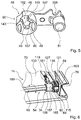
- the bearing unit 38 can optionally be detected by a locking unit 161 in a position in which the bearing unit 38 is arranged immediately before uncoupling. If this option is used, after disconnecting the household appliance door 14, guide surfaces 143, 145 of the storage unit 38 facilitate coupling the household appliance door 14 to the storage unit 38, by guiding the raised portions 72 when introduced into the receiving area 40 and thus also the storage units 68. Furthermore, in the coupling operation, the rollers 171, 173 of the guide means 24 (see FIG FIG. 1 ) in lateral grooves 175 of the household appliance door 14, which partially delimit the household appliance door 14 in an operating position laterally ( FIG. 2 ).
- the projections 72 are in the locking position. If a user then attempts to move the appliance door 14 in the direction of the surface extension 22 away from the storage unit 38, this is prevented by the projections 72 abutting the undercuts 147, as a result of which the projections 72 remain in the receiving areas 40.
- the locking means 195 engages a recess 201 of a locking means 200 of the locking unit 161, which is fixed to the guide means 24, that the guide means 24 and the locking means 200 relative to each other about an axis 204 which is parallel to the axis 193 and is rotated at a rotation of the guide means 24 with the guide means 24 are rotatable.
- the locking means 195 is with respect to the directions of rotation about the axis 193 on a housing-fixed guide member 203 (see FIG. 16 ) of the home appliance device. Therefore, when the locking means 195 is in the locking position, rotation of the guide means 24 about the axis 193 is prevented and the guide means 24 is thus fixed in a certain rotational position.
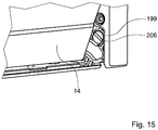
- an operator or fitter for fixing the appliance door storage unit 191 for example with the aid of a coin, can insert into a groove 206 of an actuating means 199 (FIG. FIG. 15 ), which is designed as a pivot, the locking unit 161 penetrate and this starting from a starting position, in which an opening and closing of the appliance door 14 is possible to rotate by ninety degrees ( Figures 13 and 14 ). If the home appliance door storage unit 191 is in a swing position different from the take-off swing position, the actuator 197 is cocked and thereby expanded by this rotation of the operation means 199 since the operation means 197 is fixed to the operation means 199.
- the locking means 195 Due to the tightening of the actuating means 197, the locking means 195, which is attached to the actuating means 197, in a vertical downward direction against a sliding surface 202 of the locking means 200, which is arranged on an upper side of the locking means 200 is pressed.
- a locking of the locking means 195 in the recess 201 pivots the operator or fitter the appliance door 14 in the pivot directions 10, 12 (see FIG. 1 ), wherein the locking means 195 slides on the sliding surface 202 until the domestic appliance door storage unit 191 is in the withdrawal pivot position and the locking means 195 in the recess 201 due to a pressure which the actuating means 197 on the locking means 195 downwardly engages.
Landscapes
- Engineering & Computer Science (AREA)
- Chemical & Material Sciences (AREA)
- Combustion & Propulsion (AREA)
- Mechanical Engineering (AREA)
- General Engineering & Computer Science (AREA)
- Support Devices For Sliding Doors (AREA)
- Power-Operated Mechanisms For Wings (AREA)
- Electric Ovens (AREA)
Description
Die Erfindung geht aus von einer Hausgerätetürführungsvorrichtung nach dem Oberbegriff des Anspruchs 1.The invention relates to a household appliance door guide device according to the preamble of claim 1.
Aus der Druckschrift
Die Aufgabe der Erfindung besteht insbesondere darin, eine gattungsgemäße Vorrichtung mit verbesserten Eigenschaften hinsichtlich einer einfachen Herstellbarkeit bereitzustellen.The object of the invention is in particular to provide a generic device with improved properties in terms of ease of manufacture.
Die Aufgabe wird erfindungsgemäß durch die Merkmale des Patentanspruchs 1 gelöst, während vorteilhafte Ausgestaltungen und Weiterbildungen der Erfindung den Unteransprüchen entnommen werden können.The object is achieved by the features of claim 1, while advantageous embodiments and modifications of the invention can be taken from the dependent claims.
Die Erfindung geht aus von einer Hausgerätetürführungsvorrichtung mit zumindest einem Türführungsmittel, welches wenigstens eine Führungsfläche aufweist.The invention relates to a household appliance door guide device with at least one door guide means, which has at least one guide surface.
Es wird vorgeschlagen, dass die Führungsfläche wenigstens teilweise aus einem Kunststoff gebildet ist. Mit einer erfindungsgemäßen Ausgestaltung kann eine einfache Herstellbarkeit erreicht werden. Unter einer "Führungsfläche" soll insbesondere eine Fläche verstanden werden, welche mittelbar und/oder unmittelbar eine Tür bei einer Bewegung der Tür relativ zu dem Türführungsmittel in wenigstens eine bestimmte, durch das Türführungsmittel vorgegebene Richtung führt. Unter einem "Kunststoff' soll insbesondere ein Stoff verstanden werden, welcher Polymere beinhaltet, die zumindest teilweise organische Atomgruppen aufweisen. Insbesondere kann eine präzise Führung durch die Führungsfläche erfolgen und es kann im Besonderen eine kostengünstige Bauweise erreicht werden.It is proposed that the guide surface is at least partially formed from a plastic. With an embodiment according to the invention, a simple manufacturability can be achieved. A "guide surface" is to be understood in particular as meaning a surface which indirectly and / or directly guides a door during movement of the door relative to the door guide means in at least one specific direction predetermined by the door guide means. A "plastic" is to be understood as meaning, in particular, a substance which contains polymers which at least partially have organic atomic groups, In particular, a precise guidance through the guide surface can take place and, in particular, a cost-effective construction can be achieved.
Erfindungsgemäß ist das Türführungsmittel einstückig aus Kunststoff ausgebildet. Damit kann eine einfache Montage erreicht werden. Darunter, dass das Türführungsmittel "einstückig" ausgebildet ist, soll insbesondere verstanden werden, dass es aus einem Guss ist oder aus einer Spritzung hergestellt ist und/oder einteilig ausgebildet ist und/oder durch ein Bauteil gebildet ist.According to the door guide means is integrally formed of plastic. This allows a simple installation can be achieved. By the fact that the door guide means is "integrally formed" should be understood in particular that it is made of a single cast or is made of a spray and / or is formed in one piece and / or formed by a component.
Außerdem wird vorgeschlagen, dass das Türführungsmittel eine Kulisse aufweist, welche dazu vorgesehen ist, eine Hausgerätetür zu führen. Hierdurch kann ein komfortables Betätigen der Hausgerätetür erreicht werden.It is also proposed that the door guide means comprises a gate which is intended to guide a household appliance door. This allows a comfortable operation of the appliance door can be achieved.
Vorzugsweise ist die Kulisse dazu vorgesehen, die Hausgerätetür zumindest zu einem Großteil mittels einer Schiebebewegung in einen Stauraum einzuführen. Darunter, dass die Hausgerätetür "zu einem Großteil" in den Stauraum eingebracht ist, soll insbesondere verstanden werden, dass wenigstens ein Teil der Hausgerätetür, welcher zumindest sechzig Prozent, insbesondere wenigstens fünfundsiebzig Prozent und besonders vorteilhaft wenigstens neunzig Prozent einer Vertikalerstreckung der Hausgerätetür in einem geschlossenen Zustand in einer Bedienposition bildet, in dem Stauraum angeordnet ist. Damit kann eine einfache Verstaubarkeit der Hausgerätetür erreicht werden.Preferably, the scenery is intended to introduce the home appliance door at least to a large extent by means of a sliding movement in a storage space. Under the fact that the appliance door is introduced "to a large extent" in the storage space, should be understood in particular that at least a portion of the appliance door, which at least sixty percent, in particular at least seventy-five percent and more preferably at least ninety percent of a vertical extension of the appliance door in a closed Form state in an operating position, is arranged in the storage space. Thus, a simple Verstaubarkeit the household appliance door can be achieved.
Mit Vorteil weist die Hausgerätetürführungsvorrichtung zumindest ein Dämpfungsmittel auf, welches in wenigstens einem montierten Zustand mit dem Türführungsmittel gekoppelt ist. Hiermit kann eine einfache Bauweise erreicht werden.Advantageously, the domestic appliance door guide device has at least one damping means, which is coupled in at least one mounted state with the door guide means. Hereby, a simple construction can be achieved.
Vorzugsweise ist das Dämpfungsmittel in wenigstens einem montierten Zustand zumindest teilweise in einem Aufnahmebereich des Türführungsmittels angeordnet. Auf diese Weise kann eine stabile Bauweise erreicht werden.Preferably, the damping means is at least partially disposed in a receiving region of the door guide means in at least one mounted state. In this way, a stable construction can be achieved.
Ferner wird vorgeschlagen, dass das Türführungsmittel ein Rastmittel aufweist, welches in wenigstens einem montierten Zustand das Dämpfungsmittel befestigt. Hierdurch können Bauteile eingespart werden.It is also proposed that the door guide means comprises a locking means which secures the damping means in at least one mounted state. As a result, components can be saved.
In einer bevorzugten Ausgestaltung der Erfindung weist das Türführungsmittel wenigstens eine Rippenstruktur auf. Auf diese Weise kann bei einer kostengünstigen Bauweise eine hohe Stabilität erreicht werden. Eine besonders hohe Stabilität und insbesondere Steifigkeit kann erreicht werden, wenn die Rippenstruktur wabenförmig ausgebildet ist.In a preferred embodiment of the invention, the door guide means has at least one rib structure. In this way, a high stability can be achieved in a cost-effective design. A particularly high stability and in particular rigidity can be achieved if the rib structure is honeycomb-shaped.
Ferner wird vorgeschlagen, dass die Hausgerätetürführungsvorrichtung wenigstens eine Gleitfläche des Türführungsmittels und zumindest ein Lagermittel aufweist, welches dazu vorgesehen ist, bei wenigstens einer Bewegung relativ zu dem Türführungsmittel an der Gleitfläche zu gleiten. Hierdurch kann eine präzise Bewegung des Lagermittels erreicht werden. Vorteilhafterweise ist die Gleitfläche als Teil eines Zylindermantels ausgebildet, wodurch das Lagermittel eine bedienungsfreundliche Bewegung ausführen kann.It is further proposed that the domestic appliance door guide device has at least one sliding surface of the door guide means and at least one bearing means, which is intended to slide on at least one movement relative to the door guide means on the sliding surface. As a result, a precise movement of the bearing means can be achieved. Advantageously, the sliding surface is formed as part of a cylinder jacket, whereby the bearing means can perform a user-friendly movement.
Mit Vorteil dient die Gleitfläche zu einem Gleiten des Lagermittels in wenigstens einem Verschleißzustand. Hierdurch kann eine hohe Lebensdauer erreicht werden.Advantageously, the sliding surface serves to slide the bearing means in at least one state of wear. This allows a long life can be achieved.
In einer bevorzugten Ausführungsform der Erfindung ist das Türführungsmittel zumindest teilweise aus Polypropylen und Langglasfasern gebildet. Auf diese Weise kann bei einer stabilen Konstruktion eine kostengünstige Bauweise erreicht werden. Insbesondere kann das Türführungsmittel wenigstens einen der Kunststoffe PBT GF30 bzw. PA6.6 GF30 aufweisen.In a preferred embodiment of the invention, the door guide means is at least partially formed of polypropylene and long glass fibers. In this way, a cost-effective design can be achieved with a stable construction. In particular, the door guide means may comprise at least one of the plastics PBT GF30 or PA6.6 GF30.
Vorzugsweise weist das Türführungsmittel ein Befestigungsmittel auf, welches dazu vorgesehen ist, ein Kabel zu befestigen. Hierdurch können vorteilhaft Bauteile eingespart werden.Preferably, the door guide means on a fastening means, which is intended to fasten a cable. As a result, components can advantageously be saved.
Weiterhin wird vorgeschlagen, dass die Hausgerätetürführungsvorrichtung wenigstens ein Wälzlager mit einem Metallaußenring aufweist, welcher in wenigstens einem Betriebsvorgang von der Führungsfläche geführt wird. Auf diese Weise kann ein reibungsarmer Führvorgang erreicht werden. Insbesondere wird ein leises Betriebsgeräusch ermöglicht.Furthermore, it is proposed that the domestic appliance door guide device has at least one rolling bearing with a metal outer ring, which is guided in at least one operating operation of the guide surface. In this way, a low-friction guiding operation can be achieved. In particular, a quiet operating noise is made possible.
Mit Vorteil weist das Türführungsmittel einen Aufnahmebereich auf, welcher dazu vorgesehen ist, zumindest ein Betätigungsmittel aufzunehmen. Hiermit kann eine kompakte Bauweise erreicht werden.Advantageously, the door guide means on a receiving area, which is intended to receive at least one actuating means. Hereby, a compact design can be achieved.
Vorzugsweise weist die Hausgerätetürführungsvorrichtung zumindest einen Stauraum auf, in welchen eine Hausgerätetür in wenigstens einem Benutzungszustand mittels des Türführungsmittels zumindest zu einem Großteil eingebracht ist. Auf diese Weise kann eine kompakte Anordnung erreicht werden.Preferably, the domestic appliance door guide device has at least one storage space in which a domestic appliance door is at least largely inserted in at least one state of use by means of the door guide means. In this way, a compact arrangement can be achieved.
Weitere Vorteile ergeben sich aus der folgenden Zeichnungsbeschreibung. In der Zeichnung sind Ausführungsbeispiele der Erfindung dargestellt. Die Zeichnung, die Beschreibung und die Ansprüche enthalten zahlreiche Merkmale in Kombination. Der Fachmann wird die Merkmale zweckmäßigerweise auch einzeln betrachten und zu sinnvollen weiteren Kombinationen zusammenfassen.Further advantages emerge from the following description of the drawing. In the drawings, embodiments of the invention are shown. The drawing, the description and the claims contain numerous features in combination. The expert will conveniently consider the features individually and summarize meaningful further combinations.
Es zeigen:
- Fig. 1
- ein schematisiert dargestelltes, als Backofen ausgebildetes Hausgerät mit einer erfindungsgemäßen Hausgerätvorrichtung bei entnommener Hausgerätetür,
- Fig. 2
- ein Ende der Hausgerätetür,
- Fig. 3
- eine schematische Darstellung des Hausgeräts in einem unvollständig montierten Zustand, insbesondere ohne die Hausgerätetür,
- Fig. 4
- eine schematische Darstellung einer Lagereinheit,
- Fig. 5
- ein Drehmomentübertragungsmittel der Lagereinheit,
- Fig. 6
- eine Ansicht des Endes der Hausgerätetür mit einer Achseneinheit bei demontierten Innen- und Zwischenscheiben schräg unten,
- Fig. 7
- eine schematische Darstellung der von der Lagereinheit abgekoppelten Hausgerätetür ohne eine Zwischenscheibe und eine Innenscheibe,
- Fig. 8
- eine schematische Darstellung der geschlossenen Hausgerätetür in einer seitlichen Ansicht,
- Fig. 9
- eine schematische Darstellung der offenen Hausgerätetür in einer seitlichen Ansicht,
- Fig. 10
- eine schematische Darstellung eines Entriegelungszustands einer Verriegelungseinheit,
- Fig. 11
- eine schematische Darstellung einer Verriegelungsposition der Verriegelungseinheit,
- Fig. 12
- eine schematische Darstellung des Drehmomentübertragungsmittels und der Hausgerätetür in einer geöffneten Position,
- Fig. 13
- eine Arretierungseinheit der Hausgerätvorrichtung mit einem Feststellmittel in einer Ausgangsstellung, wobei sich die Hausgerätvorrichtung in einem teilweise demontierten Zustand befindet,
- Fig. 14
- eine Arretierungseinheit der Hausgerätvorrichtung mit einem Feststellmittel in einer Arretierungsposition, wobei sich die Hausgerätvorrichtung in einem teilweise demontierten Zustand befindet,
- Fig. 15
- ein unteres Ende des Hausgeräts mit einem Teil der teilweise geöffneten Hausgerätetür und einem Betätigungsmittel der Arretierungseinheit,
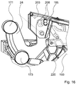
- Fig. 16
- ein Führungsmittel und ein gehäusefestes Führelement der Hausgerätvorrichtung,
- Fig. 17
- ein Türführungsmittel einer Hausgerätetürführungsvorrichtung des Hausgeräts,
- Fig. 18
- eine Teilansicht des Türführungsmittels,
- Fig. 19
- ein an dem Türführungsmittel befestigtes Lagermittel und das Türführungsmittel und
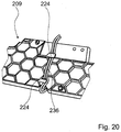
- Fig. 20
- eine Außenseite des Türführungsmittels.
- Fig. 1
- a schematically illustrated, designed as an oven domestic appliance with a domestic appliance device according to the invention with the household appliance door removed,
- Fig. 2
- an end of the household appliance door,
- Fig. 3
- a schematic representation of the domestic appliance in an incompletely mounted state, in particular without the appliance door,
- Fig. 4
- a schematic representation of a storage unit,
- Fig. 5
- a torque transmitting means of the bearing unit,
- Fig. 6
- a view of the end of the appliance door with an axis unit with disassembled inner and intermediate plates obliquely below,
- Fig. 7
- a schematic representation of the decoupled from the storage unit household appliance door without a washer and an inner pane,
- Fig. 8
- a schematic representation of the closed appliance door in a side view,
- Fig. 9
- a schematic representation of the open household appliance door in a side view,
- Fig. 10
- a schematic representation of a release state of a locking unit,
- Fig. 11
- a schematic representation of a locking position of the locking unit,
- Fig. 12
- a schematic representation of the torque transmitting means and the appliance door in an open position,
- Fig. 13
- a locking unit of the domestic appliance device with a locking means in a starting position, wherein the domestic appliance device is in a partially disassembled state,
- Fig. 14
- a locking unit of the domestic appliance device with a locking means in a locking position, wherein the domestic appliance device is in a partially disassembled state,
- Fig. 15
- a lower end of the domestic appliance with a part of the partially opened domestic appliance door and an actuating means of the locking unit,
- Fig. 16
- a guide means and a housing-fixed guide element of the household appliance device,
- Fig. 17
- a door guide means of a household appliance door guide device of the household appliance,
- Fig. 18
- a partial view of the door guide means,
- Fig. 19
- a bearing means attached to the door guide means and the door guide means and
- Fig. 20
- an outside of the door guide means.
Die Koppeleinheit 34, welche ein Teil der Türlagereinheit 20 ist, ist von einer Achseneinheit 54 gebildet, welche eine sechskantige Stahlstange 66 und zwei aus Kunststoff einstückig ausgebildete Lagereinheiten 68 aufweist, welche jeweils an einem Ende der Stahlstange 66 formschlüssig befestigt sind und zueinander spiegelverkehrt ausgebildet sind. In eine Umfangsrichtung 70 der Stahlstange 66 ist die Türeinheit 64 von den Lagereinheiten 68 drehbar um eine Achse 76 gelagert, welche in eine horizontale Richtung verläuft. Hierzu weisen die Lagereinheiten 68 Gleitlagerflächen 84 auf (
Der Kontaktbereich 36 ist von einem Endabschnitt 56 der Achseneinheit 54 gebildet (
Des Weiteren bildet die Erhebung 72 ein weiteres Funktionsmittel 88 - nämlich ein Führungsmittel 58 - der Lagereinheit 68, indem der Kontaktbereich 36 bei einem Abkoppeln der Hausgerätetür 14 von der Lagereinheit 38 an der Anlagefläche 46 gleitet und dabei die Hausgerätetür 14 führt. Der Kontaktbereich 36 fungiert demzufolge als Führungsfläche 82. Eine Wartung bzw. Reinigung der Hausgerätetür 14 kann durch das Abkoppeln vorteilhaft erfolgen.Furthermore, the
Die Türeinheit 64 ist als Profilschienentür ausgebildet und weist zwei Profilschienen 121, 123 auf. Die Lagereinheiten 68 sind teilweise in Ausnehmungen 163 der Profilschienen 121, 123 angeordnet. Die Ausnehmungen 163 werden von nicht näher dargestellten Lagerflächen der Profilschienen 121, 123 begrenzt. Bei einem Öffnen der Hausgerätetür 14 gleiten die Gleitlagerflächen 84 der Lagereinheiten 68 an den korrespondierenden Lagerflächen der Profilschienen 121, 123. Ferner sind mittels der Profilschienen 121, 123 die Rollen 111, 113 und damit der Türgriff 62 drehbar gelagert. An den Profilschienen 121, 123 ist je ein Befestigungsmittel 98 relativ zu den Profilschienen 121, 123 unbeweglich befestigt. Eine Öse 125 des Befestigungsmittels 98, welches einstückig ausgebildet ist und in einem vollständig montierten Zustand als Scheibenbefestigungsmittel für die Innenscheibe 141 und die Zwischenscheibe fungiert, weist einen ersten und einen zweiten Befestigungsbereich 100, 104 auf, welche relativ zu der Achse 92 unbeweglich sind.The
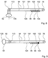
Die Türeinheit 64 weist außerdem ein erstes und ein zweites Federmittel 96, 102 auf, welche als Spiralfedern ausgebildet sind. Ein erstes Ende des ersten Federmittels 96 ist an dem ersten Befestigungsbereich 100 eingehängt, ein erstes Ende des zweiten Federmittels 102 ist an dem zweiten Befestigungsbereich 104 eingehängt. An zwei Enden des Seilzugs 181 sind ferner Ösen 117, 119 der Drehmomentübertragungsmittel 94, 95 befestigt. Ein zweites Ende des Federmittels 96 ist ferner an der Öse 117 befestigt. Das Federmittel 96 ist zwischen der Öse 125 und der Rolle 113 angeordnet. Ein zweites Ende des zweiten Federmittels 102 ist an der Öse 119 befestigt. Das zweite Federmittel 102 ist zwischen der Öse 125 und der Lagereinheit 68 angeordnet. Haupterstreckungsrichtungen der Federmittel 96, 102 sind parallel zu der Flächenerstreckung 22. Ein Teilabschnitt 129 des Drehmomentübertragungsmittels 94, welcher an der Öse 117 befestigt ist, verläuft parallel und direkt neben einer Außenscheibe 133 der Türeinheit 64. Ein zweiter Teilabschnitt 131 verläuft parallel zu dem ersten Teilabschnitt 129 und parallel zu der Innenscheibe 141 der Türeinheit 64 und ist direkt neben der Innenscheibe 141 angeordnet. Der Teilabschnitt 129 ist zwischen dem Teilabschnitt 131 und der Außenscheibe 133 angeordnet.The
Das erste Federmittel 96 weist eine deutlich größere Federhärte auf als das zweite Federmittel 102. Die Federmittel 96, 102 halten den Seilzug 181 in einem montierten Zustand gespannt. Mittels einer Drehung des Türgriffs 62 relativ zu den Profilschienen 121, 123 um die Achse 92 wird mit Hilfe der Rollen 111, 113 und der Drehmomentübertragungsmittel 94, 95 ein Drehmoment auf die Lagereinheiten 68 übertragen.The first spring means 96 has a significantly greater spring stiffness than the second spring means 102. The spring means 96, 102 keep the
Außerdem wird bei einer Drehung der Lagereinheiten 68 um die Achse 76 relativ zu den Profilschienen 121, 123 mittels der Drehmomentübertragungsmittel 94, 95 und der Rollen 111, 113 ein Drehmoment auf den Türgriff 62 übertragen. Eine Drehung der Profilschienen 121, 123 relativ zu den Lagereinheiten 68 findet beim Öffnen und Schließen der Hausgerätetür 14 statt.In addition, upon rotation of the bearing
Die Lagereinheit 68 und das Drehmomentübertragungsmittel 48 bilden eine Verriegelungseinheit 108. In einem Benutzungszustand, in welchem das Hausgerät 26 vollständig montiert ist und in welchem der Benutzer den Türgriff 62 nur zu einem Öffnen bzw. einem Schließen der Hausgerätetür 14 verwendet, ist die Verriegelungseinheit 108 in einem Entriegelungszustand (
Die Verriegelungseinheit 108 ist ferner dazu vorgesehen, in einer wenigstens teilweise geöffneten Position der Hausgerätetür 14 ein Entfernen der Hausgerätetür 14 von der Lagereinheit 38 zu verhindern. Bringt beispielsweise ein Benutzer bzw. ein Monteur die Hausgerätetür 14 in eine Position, in welcher die Flächenerstreckung 22 einen Winkel von etwa zwanzig Grad mit einer Vertikalen einschließt, und bewegt den Türgriff 62 in Richtung der Flächenerstreckung 22 nach oben, so dreht der Türgriff 62 mittels einer Kopplungseinheit 139, welche durch die Rollen 111, 113, die Drehmomentübertragungsmittel 94, 95 und die Bolzen 115 gebildet ist, die Lagereinheiten 68 relativ zu den Profilschienen 121, 123 um die Achse 76. Hierdurch bewegen sich die Erhebungen 72 in eine Verriegelungsposition (
Bei einer Montage der Hausgerätetür 14 werden zunächst die Profilschienen 121, 123 auf die Außenscheibe 133 aufgeklebt (
Das Führungsmittel 24, welches drehbar um eine horizontal verlaufende Achse 193 gelagert ist, und die Lagereinheit 38 bilden eine Hausgerätetürlagereinheit 191, welche die Hausgerätetür 14 schwenkbar um die Achse 193 lagert (
Ferner ist das Arretiermittel 200 dazu vorgesehen, eine Federkraft auf das Führungsmittel 24 zu übertragen. An dem Arretiermittel 200 ist eine Spiralfeder 207 eingehängt, welche bei einem Öffnen der Hausgerätetür 14 ausgedehnt wird und einen Teil der Lageenergie, welchen die Hausgerätetür 14 in einem geschlossenen Zustand besitzt, speichert und somit als Energiespeichereinheit dient.Furthermore, the locking means 200 is provided to transmit a spring force to the guide means 24. On the locking means 200, a
Die Drehmomentübertragungsmittel 48, 50 sind ferner Teile der Hausgerätetürlagereinheit 191. Sie weisen jeweils eine Einbuchtung 205 (
Befindet sich die Hausgerätetür 14 in einer teilweise geöffnete Position, so kann ein Bediener bzw. Monteur zur Fixierung der Hausgerätetürlagereinheit 191 beispielsweise mit Hilfe eines Geldstücks in eine Nut 206 eines Betätigungsmittels 199 (
Das Hausgerät 26 weist weiterhin eine Hausgerätetürführungsvorrichtung auf.
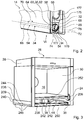
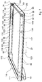
Bei einem Einbringen der Hausgerätetür 14 in den Stauraum 18 wird die Hausgerätetür 14 zumindest teilweise durch die Hausgerätetürführungsvorrichtung abgebremst. Zu diesem Zweck weist die Hausgerätetürführungsvorrichtung ein Dämpfungsmittel 212 auf (Figur 3), welches aus einem aus Polyurethan gebildeten Quader gebildet ist. An einem der Rückseite des Hausgeräts zugewandten Endbereich der Führungskulisse 44 weist das Türführungsmittel 209 einen Aufnahmebereich 214 auf. Das Dämpfungsmittel 212 ist an einem Rastmittel 216 des Türführungsmittels 209, welches in dem Aufnahmebereich 214 angeordnet ist, eingerastet und ist teilweise in dem Aufnahmebereich 214 angeordnet. Am Ende eines Einführungsvorgangs der Hausgerätetür 14 in den Stauraum 18 stößt das Drehmomentübertragungsmittel 50 (siehe
Ein Teil des Türführungsmittels 209, welches die Führungskulisse 44 teilweise umgibt, weist eine Rippenstruktur 218 auf, welche durch ein Muster mit wabenförmigen Zellen 230 gebildet ist. Ferner bildet das Türführungsmittel 209 einen Aufnahmebereich 228, welcher an eine Frontseite des Stauraums direkt angrenzt. In einem montierten Zustand ist in dem Aufnahmebereich 228 das Betätigungsmittel 199 angeordnet und von dem Türführungsmittel 209 drehbar gelagert (siehe
Das Führungsmittel 24, welches ein Lagermittel 222 bildet und ein Schwenken der Hausgerätetür 14 erlaubt, wird von dem Türführungsmittel 209 drehbar gelagert. In einem Verschleißzustand der drehbaren Lagerung des Lagermittels 222 könnte das Lagermittel 222 in einem Vergleich zu einem Neuzustand des Hausgeräts einen Spielraum in eine seitliche, horizontale Richtung weg von dem Stauraum 18 haben. Aufgrund einer Gleitfläche 220 (
An einer Seite des Türführungsmittels 209, welche in einem montierten Zustand einem Außenbereich des Hausgeräts zugewandt ist, weist das Türführungsmittel 209 ein Befestigungsmittel 224 zu einer Befestigung eines Kabels 236 einer Beleuchtung des Hausgeräts auf (
Teile des Hausgerätegehäuses 28 sind direkt an das Türführungsmittels 209 angeschraubt (
An einem an die Frontseite des Hausgeräts angrenzenden Bereich 248 weist das Türführungsmittel 209 an einem Endabschnitt der Führungskulisse 44 eine Einbuchtung auf, durch welche die Lagereinheit 38 aus der Führungskulisse 44 entnehmbar ist. Vor einem solchen Entnehmen der Lagereinheit 38 muss die Kopplung der Lagereinheit 38 mit dem als Zahn ausgebildeten Arretiermittel 189 aufgehoben werden.At an
Wird das Hausgerät 26 angehoben und auf den Boden 238 bzw. eine Kante des Bodens 238 fallen gelassen, so werden bei einem Aufprall des Hausgeräts 26 auf Teile des Hausgeräts 26 wirkende Kräfte an das Türführungsmittel 209 weitergegeben. Diese Teile sind in einem hinteren Bereich des Hausgeräts 26 beispielsweise die Seitenwände 240, in einem mittleren Bereich des Hausgeräts 26 der Zwischenboden 242 und die Seitenwände 240 und in einem vorderen Bereich des Hausgeräts 26 ein Backrohrflansch 252, die Lisene und eine Tropfrinne 250, welche von dem Boden 238 gebildet ist. Das Türführungsmittel 209 weist eine Erhebung 254 auf (
Das Türführungsmittel 209 wird in einem Spritzverfahren hergestellt.
The door guide means 209 is manufactured in a spraying process.
Claims (15)
- Domestic appliance door guide device with at least one door guide means (209), which has at least one guiding surface (210),
characterised in that
the guiding surface (210) is formed at least partially from a plastic, with the door guide means (209) being made of a single piece of plastic. - Domestic appliance door guide device according to claim 1,
characterised in that
the door guide means (209) has a connecting member (44) that is provided to guide a domestic appliance door (14). - Domestic appliance door guide device according to claim 2,
characterised in that
the connecting member (44) is provided to guide the domestic appliance door (14) into a storage space (18) at least for the most part by means of a pushing movement. - Domestic appliance door guide device according to one of the preceding claims,
characterised by
at least one damping means (212) that is coupled to the door guide means (209) in at least one installed state. - Domestic appliance door guide device according to claim 4,
characterised in that
the damping means (212) is arranged in at least one installed state at least partially in a receiving area (214) of the door guide means (209). - Domestic appliance door guide device according to one of claims 4 or 5,
characterised in that
the door guide means (209) has a latching means (216) that fixes the damping means (212) in at least one installed state. - Domestic appliance door guide device according to one of the preceding claims,
characterised in that
the door guide means (209) has at least one web structure (218). - Domestic appliance door guide device according to claim 7,
characterised in that
the web structure (218) has a honeycomb pattern. - Domestic appliance door guide device according to one of the preceding claims,
characterised by
at least one sliding surface (220) of the door guide means (209) and at least one bearing means (222), which is provided, in the event of at least one movement relative to the door guide means (209), to slide along the sliding surface (220). - Domestic appliance door guide device according to claim 9,
characterised in that
the sliding surface (220) is realised as part of a cylindrical sheath. - Domestic appliance door guide device according to one of claims 9 or 10,
characterised in that
the sliding surface (220) is intended for sliding the bearing means (222) in at least one state of wear. - Domestic appliance door guide device according to one of the preceding claims,
characterized in that
the door guide means (209) has at least one subregion that is formed of at least polypropylene and/or long glass fibres. - Domestic appliance door guide device according to one of the preceding claims,
characterised in that
the door guide means (209) has a fixing means (224) that is provided to fix a cable. - Domestic appliance door guide device according to one of the preceding claims,
characterised by
at least one roller bearing (42) with a metal outer ring, which is guided by the guiding surface (210) in at least one operation. - Domestic appliance door guide device according to one of the preceding claims,
characterised in that
the door guide means (209) has at least one receiving area (228) that is provided to receive at least one actuating means (199).
Applications Claiming Priority (1)
| Application Number | Priority Date | Filing Date | Title |
|---|---|---|---|
| DE102008010502A DE102008010502A1 (en) | 2008-02-22 | 2008-02-22 | House door guiding device |
Publications (3)
| Publication Number | Publication Date |
|---|---|
| EP2093495A2 EP2093495A2 (en) | 2009-08-26 |
| EP2093495A3 EP2093495A3 (en) | 2014-04-02 |
| EP2093495B1 true EP2093495B1 (en) | 2016-02-17 |
Family
ID=40679289
Family Applications (1)
| Application Number | Title | Priority Date | Filing Date |
|---|---|---|---|
| EP09100130.5A Active EP2093495B1 (en) | 2008-02-22 | 2009-02-19 | Door guide device for household device |
Country Status (2)
| Country | Link |
|---|---|
| EP (1) | EP2093495B1 (en) |
| DE (1) | DE102008010502A1 (en) |
Cited By (1)
| Publication number | Priority date | Publication date | Assignee | Title |
|---|---|---|---|---|
| US12035845B1 (en) | 2023-04-26 | 2024-07-16 | Sharkninja Operating Llc | Systems and methods for cooking pizza |
Families Citing this family (3)
| Publication number | Priority date | Publication date | Assignee | Title |
|---|---|---|---|---|
| DE102012222161A1 (en) | 2012-12-04 | 2014-06-05 | BSH Bosch und Siemens Hausgeräte GmbH | Cooking appliance with retractable door and height-adjustable guide slot |
| TR201820546A1 (en) * | 2018-12-26 | 2020-07-21 | Arcelik As | AN OVEN WITH ADJUSTABLE HEIGHT RAIL |
| JP7288572B2 (en) * | 2019-11-06 | 2023-06-08 | 株式会社エー・アンド・デイ | Wind shield for balance |
Family Cites Families (5)
| Publication number | Priority date | Publication date | Assignee | Title |
|---|---|---|---|---|
| DE8515431U1 (en) * | 1985-05-24 | 1987-05-14 | Bosch-Siemens Hausgeräte GmbH, 8000 München | oven |
| DE10208490A1 (en) | 2002-02-27 | 2004-02-05 | BSH Bosch und Siemens Hausgeräte GmbH | household appliance |
| DE10211470A1 (en) * | 2002-03-15 | 2003-10-02 | Electrolux Home Prod Corp | Rail of a telescopic pull-out system, in particular, for items to be cooked in a cooking oven and pull-out system |
| DE10228297A1 (en) * | 2002-06-25 | 2004-01-15 | BSH Bosch und Siemens Hausgeräte GmbH | Domestic cooking appliance has a drip sliding tray which is silently guided in a track formed in the side wall with an absorbent material between metal plates |
| EP2026013A1 (en) * | 2007-08-17 | 2009-02-18 | Electrolux Home Products Corporation N.V. | Domestic appliance comprising pullout door carriage and traction-assisting mechanism |
-
2008
- 2008-02-22 DE DE102008010502A patent/DE102008010502A1/en not_active Ceased
-
2009
- 2009-02-19 EP EP09100130.5A patent/EP2093495B1/en active Active
Cited By (1)
| Publication number | Priority date | Publication date | Assignee | Title |
|---|---|---|---|---|
| US12035845B1 (en) | 2023-04-26 | 2024-07-16 | Sharkninja Operating Llc | Systems and methods for cooking pizza |
Also Published As
| Publication number | Publication date |
|---|---|
| DE102008010502A1 (en) | 2009-08-27 |
| EP2093495A2 (en) | 2009-08-26 |
| EP2093495A3 (en) | 2014-04-02 |
Similar Documents
| Publication | Publication Date | Title |
|---|---|---|
| EP2093492B1 (en) | Household device | |
| WO2020103981A1 (en) | Parking lock and method for the assembly thereof | |
| EP1659298B1 (en) | Linear drive | |
| EP1481142B1 (en) | Household appliance and household appliance door | |
| EP1848900A2 (en) | Electromotive linear drive | |
| EP2189725A2 (en) | Household device | |
| EP1481198B1 (en) | Household device | |
| EP2093495B1 (en) | Door guide device for household device | |
| EP1481141B1 (en) | Household appliance and household appliance door | |
| EP1481140B1 (en) | Door for domestic appliances and corresponding domestic appliance | |
| EP1481197B1 (en) | Household device | |
| DE102005002822B4 (en) | Door hinge for a household appliance | |
| EP1481199B1 (en) | Method for the production of a household appliance and household appliance | |
| EP2093493B1 (en) | Household device | |
| EP2093496B1 (en) | Household device | |
| DE102008010498B4 (en) | home appliance device | |
| EP2806769B1 (en) | Pull-in system for multiple pull-out furniture parts | |
| EP2486309A1 (en) | Shifting device | |
| WO2015173297A1 (en) | Bearing assembly for a door | |
| EP2093494B1 (en) | Household device | |
| EP3356629B1 (en) | Fitting for a sliding door and method for mounting a sliding door | |
| DE2911024A1 (en) | Motor-driven window-pane adjusting mechanism - uses relative movement between dog clutch halves to release locking mechanism | |
| WO2023110169A1 (en) | Suspension assembly for a sliding door | |
| WO2024013675A1 (en) | Longitudinal adjustment device and vehicle seat | |
| WO2015018416A2 (en) | Bracing arrangement for a drivetrain of a motor vehicle |
Legal Events
| Date | Code | Title | Description |
|---|---|---|---|
| PUAI | Public reference made under article 153(3) epc to a published international application that has entered the european phase |
Free format text: ORIGINAL CODE: 0009012 |
|
| AK | Designated contracting states |
Kind code of ref document: A2 Designated state(s): AT BE BG CH CY CZ DE DK EE ES FI FR GB GR HR HU IE IS IT LI LT LU LV MC MK MT NL NO PL PT RO SE SI SK TR |
|
| AX | Request for extension of the european patent |
Extension state: AL BA RS |
|
| PUAL | Search report despatched |
Free format text: ORIGINAL CODE: 0009013 |
|
| AK | Designated contracting states |
Kind code of ref document: A3 Designated state(s): AT BE BG CH CY CZ DE DK EE ES FI FR GB GR HR HU IE IS IT LI LT LU LV MC MK MT NL NO PL PT RO SE SI SK TR |
|
| AX | Request for extension of the european patent |
Extension state: AL BA RS |
|
| RIC1 | Information provided on ipc code assigned before grant |
Ipc: F25D 23/02 20060101ALI20140225BHEP Ipc: D06F 37/10 20060101ALI20140225BHEP Ipc: A47L 15/42 20060101ALI20140225BHEP Ipc: F24C 15/02 20060101AFI20140225BHEP |
|
| 17P | Request for examination filed |
Effective date: 20141002 |
|
| RBV | Designated contracting states (corrected) |
Designated state(s): AT BE BG CH CY CZ DE DK EE ES FI FR GB GR HR HU IE IS IT LI LT LU LV MC MK MT NL NO PL PT RO SE SI SK TR |
|
| AKX | Designation fees paid |
Designated state(s): AT BE BG CH CY CZ DE DK EE ES FI FR GB GR HR HU IE IS IT LI LT LU LV MC MK MT NL NO PL PT RO SE SI SK TR |
|
| AXX | Extension fees paid |
Extension state: AL Extension state: BA Extension state: RS |
|
| RAP1 | Party data changed (applicant data changed or rights of an application transferred) |
Owner name: BSH HAUSGERAETE GMBH |
|
| 17Q | First examination report despatched |
Effective date: 20150316 |
|
| GRAP | Despatch of communication of intention to grant a patent |
Free format text: ORIGINAL CODE: EPIDOSNIGR1 |
|
| INTG | Intention to grant announced |
Effective date: 20150918 |
|
| GRAS | Grant fee paid |
Free format text: ORIGINAL CODE: EPIDOSNIGR3 |
|
| GRAA | (expected) grant |
Free format text: ORIGINAL CODE: 0009210 |
|
| AK | Designated contracting states |
Kind code of ref document: B1 Designated state(s): AT BE BG CH CY CZ DE DK EE ES FI FR GB GR HR HU IE IS IT LI LT LU LV MC MK MT NL NO PL PT RO SE SI SK TR |
|
| REG | Reference to a national code |
Ref country code: GB Ref legal event code: FG4D Free format text: NOT ENGLISH |
|
| REG | Reference to a national code |
Ref country code: CH Ref legal event code: EP |
|
| REG | Reference to a national code |
Ref country code: IE Ref legal event code: FG4D Free format text: LANGUAGE OF EP DOCUMENT: GERMAN |
|
| REG | Reference to a national code |
Ref country code: AT Ref legal event code: REF Ref document number: 775834 Country of ref document: AT Kind code of ref document: T Effective date: 20160315 |
|
| REG | Reference to a national code |
Ref country code: FR Ref legal event code: PLFP Year of fee payment: 8 |
|
| REG | Reference to a national code |
Ref country code: DE Ref legal event code: R096 Ref document number: 502009012139 Country of ref document: DE |
|
| REG | Reference to a national code |
Ref country code: NL Ref legal event code: MP Effective date: 20160217 |
|
| REG | Reference to a national code |
Ref country code: LT Ref legal event code: MG4D |
|
| PG25 | Lapsed in a contracting state [announced via postgrant information from national office to epo] |
Ref country code: NO Free format text: LAPSE BECAUSE OF FAILURE TO SUBMIT A TRANSLATION OF THE DESCRIPTION OR TO PAY THE FEE WITHIN THE PRESCRIBED TIME-LIMIT Effective date: 20160517 Ref country code: ES Free format text: LAPSE BECAUSE OF FAILURE TO SUBMIT A TRANSLATION OF THE DESCRIPTION OR TO PAY THE FEE WITHIN THE PRESCRIBED TIME-LIMIT Effective date: 20160217 Ref country code: IT Free format text: LAPSE BECAUSE OF FAILURE TO SUBMIT A TRANSLATION OF THE DESCRIPTION OR TO PAY THE FEE WITHIN THE PRESCRIBED TIME-LIMIT Effective date: 20160217 Ref country code: GR Free format text: LAPSE BECAUSE OF FAILURE TO SUBMIT A TRANSLATION OF THE DESCRIPTION OR TO PAY THE FEE WITHIN THE PRESCRIBED TIME-LIMIT Effective date: 20160518 Ref country code: FI Free format text: LAPSE BECAUSE OF FAILURE TO SUBMIT A TRANSLATION OF THE DESCRIPTION OR TO PAY THE FEE WITHIN THE PRESCRIBED TIME-LIMIT Effective date: 20160217 |
|
| PG25 | Lapsed in a contracting state [announced via postgrant information from national office to epo] |
Ref country code: LV Free format text: LAPSE BECAUSE OF FAILURE TO SUBMIT A TRANSLATION OF THE DESCRIPTION OR TO PAY THE FEE WITHIN THE PRESCRIBED TIME-LIMIT Effective date: 20160217 Ref country code: SE Free format text: LAPSE BECAUSE OF FAILURE TO SUBMIT A TRANSLATION OF THE DESCRIPTION OR TO PAY THE FEE WITHIN THE PRESCRIBED TIME-LIMIT Effective date: 20160217 Ref country code: NL Free format text: LAPSE BECAUSE OF FAILURE TO SUBMIT A TRANSLATION OF THE DESCRIPTION OR TO PAY THE FEE WITHIN THE PRESCRIBED TIME-LIMIT Effective date: 20160217 Ref country code: BE Free format text: LAPSE BECAUSE OF NON-PAYMENT OF DUE FEES Effective date: 20160229 Ref country code: PL Free format text: LAPSE BECAUSE OF FAILURE TO SUBMIT A TRANSLATION OF THE DESCRIPTION OR TO PAY THE FEE WITHIN THE PRESCRIBED TIME-LIMIT Effective date: 20160217 Ref country code: PT Free format text: LAPSE BECAUSE OF FAILURE TO SUBMIT A TRANSLATION OF THE DESCRIPTION OR TO PAY THE FEE WITHIN THE PRESCRIBED TIME-LIMIT Effective date: 20160617 Ref country code: LT Free format text: LAPSE BECAUSE OF FAILURE TO SUBMIT A TRANSLATION OF THE DESCRIPTION OR TO PAY THE FEE WITHIN THE PRESCRIBED TIME-LIMIT Effective date: 20160217 |
|
| REG | Reference to a national code |
Ref country code: CH Ref legal event code: PL |
|
| PG25 | Lapsed in a contracting state [announced via postgrant information from national office to epo] |
Ref country code: DK Free format text: LAPSE BECAUSE OF FAILURE TO SUBMIT A TRANSLATION OF THE DESCRIPTION OR TO PAY THE FEE WITHIN THE PRESCRIBED TIME-LIMIT Effective date: 20160217 Ref country code: LI Free format text: LAPSE BECAUSE OF NON-PAYMENT OF DUE FEES Effective date: 20160229 Ref country code: CH Free format text: LAPSE BECAUSE OF NON-PAYMENT OF DUE FEES Effective date: 20160229 Ref country code: EE Free format text: LAPSE BECAUSE OF FAILURE TO SUBMIT A TRANSLATION OF THE DESCRIPTION OR TO PAY THE FEE WITHIN THE PRESCRIBED TIME-LIMIT Effective date: 20160217 |
|
| REG | Reference to a national code |
Ref country code: DE Ref legal event code: R097 Ref document number: 502009012139 Country of ref document: DE |
|
| PG25 | Lapsed in a contracting state [announced via postgrant information from national office to epo] |
Ref country code: CZ Free format text: LAPSE BECAUSE OF FAILURE TO SUBMIT A TRANSLATION OF THE DESCRIPTION OR TO PAY THE FEE WITHIN THE PRESCRIBED TIME-LIMIT Effective date: 20160217 Ref country code: RO Free format text: LAPSE BECAUSE OF FAILURE TO SUBMIT A TRANSLATION OF THE DESCRIPTION OR TO PAY THE FEE WITHIN THE PRESCRIBED TIME-LIMIT Effective date: 20160217 Ref country code: SK Free format text: LAPSE BECAUSE OF FAILURE TO SUBMIT A TRANSLATION OF THE DESCRIPTION OR TO PAY THE FEE WITHIN THE PRESCRIBED TIME-LIMIT Effective date: 20160217 |
|
| REG | Reference to a national code |
Ref country code: IE Ref legal event code: MM4A |
|
| PLBE | No opposition filed within time limit |
Free format text: ORIGINAL CODE: 0009261 |
|
| STAA | Information on the status of an ep patent application or granted ep patent |
Free format text: STATUS: NO OPPOSITION FILED WITHIN TIME LIMIT |
|
| 26N | No opposition filed |
Effective date: 20161118 |
|
| PG25 | Lapsed in a contracting state [announced via postgrant information from national office to epo] |
Ref country code: IE Free format text: LAPSE BECAUSE OF NON-PAYMENT OF DUE FEES Effective date: 20160219 |
|
| REG | Reference to a national code |
Ref country code: FR Ref legal event code: PLFP Year of fee payment: 9 |
|
| PG25 | Lapsed in a contracting state [announced via postgrant information from national office to epo] |
Ref country code: SI Free format text: LAPSE BECAUSE OF FAILURE TO SUBMIT A TRANSLATION OF THE DESCRIPTION OR TO PAY THE FEE WITHIN THE PRESCRIBED TIME-LIMIT Effective date: 20160217 Ref country code: BG Free format text: LAPSE BECAUSE OF FAILURE TO SUBMIT A TRANSLATION OF THE DESCRIPTION OR TO PAY THE FEE WITHIN THE PRESCRIBED TIME-LIMIT Effective date: 20160517 |
|
| REG | Reference to a national code |
Ref country code: AT Ref legal event code: MM01 Ref document number: 775834 Country of ref document: AT Kind code of ref document: T Effective date: 20160219 |
|
| PG25 | Lapsed in a contracting state [announced via postgrant information from national office to epo] |
Ref country code: AT Free format text: LAPSE BECAUSE OF NON-PAYMENT OF DUE FEES Effective date: 20160219 |
|
| PG25 | Lapsed in a contracting state [announced via postgrant information from national office to epo] |
Ref country code: MT Free format text: LAPSE BECAUSE OF FAILURE TO SUBMIT A TRANSLATION OF THE DESCRIPTION OR TO PAY THE FEE WITHIN THE PRESCRIBED TIME-LIMIT Effective date: 20160217 |
|
| REG | Reference to a national code |
Ref country code: FR Ref legal event code: PLFP Year of fee payment: 10 |
|
| PG25 | Lapsed in a contracting state [announced via postgrant information from national office to epo] |
Ref country code: HU Free format text: LAPSE BECAUSE OF FAILURE TO SUBMIT A TRANSLATION OF THE DESCRIPTION OR TO PAY THE FEE WITHIN THE PRESCRIBED TIME-LIMIT; INVALID AB INITIO Effective date: 20090219 Ref country code: CY Free format text: LAPSE BECAUSE OF FAILURE TO SUBMIT A TRANSLATION OF THE DESCRIPTION OR TO PAY THE FEE WITHIN THE PRESCRIBED TIME-LIMIT Effective date: 20160217 |
|
| PG25 | Lapsed in a contracting state [announced via postgrant information from national office to epo] |
Ref country code: MK Free format text: LAPSE BECAUSE OF FAILURE TO SUBMIT A TRANSLATION OF THE DESCRIPTION OR TO PAY THE FEE WITHIN THE PRESCRIBED TIME-LIMIT Effective date: 20160217 Ref country code: HR Free format text: LAPSE BECAUSE OF FAILURE TO SUBMIT A TRANSLATION OF THE DESCRIPTION OR TO PAY THE FEE WITHIN THE PRESCRIBED TIME-LIMIT Effective date: 20160217 Ref country code: LU Free format text: LAPSE BECAUSE OF NON-PAYMENT OF DUE FEES Effective date: 20160219 Ref country code: MC Free format text: LAPSE BECAUSE OF FAILURE TO SUBMIT A TRANSLATION OF THE DESCRIPTION OR TO PAY THE FEE WITHIN THE PRESCRIBED TIME-LIMIT Effective date: 20160217 Ref country code: TR Free format text: LAPSE BECAUSE OF FAILURE TO SUBMIT A TRANSLATION OF THE DESCRIPTION OR TO PAY THE FEE WITHIN THE PRESCRIBED TIME-LIMIT Effective date: 20160217 Ref country code: IS Free format text: LAPSE BECAUSE OF FAILURE TO SUBMIT A TRANSLATION OF THE DESCRIPTION OR TO PAY THE FEE WITHIN THE PRESCRIBED TIME-LIMIT Effective date: 20160217 |
|
| PGFP | Annual fee paid to national office [announced via postgrant information from national office to epo] |
Ref country code: FR Payment date: 20200220 Year of fee payment: 12 |
|
| PG25 | Lapsed in a contracting state [announced via postgrant information from national office to epo] |
Ref country code: FR Free format text: LAPSE BECAUSE OF NON-PAYMENT OF DUE FEES Effective date: 20210228 |
|
| REG | Reference to a national code |
Ref country code: DE Ref legal event code: R084 Ref document number: 502009012139 Country of ref document: DE |
|
| PGFP | Annual fee paid to national office [announced via postgrant information from national office to epo] |
Ref country code: DE Payment date: 20240229 Year of fee payment: 16 Ref country code: GB Payment date: 20240222 Year of fee payment: 16 |
|
| PGFP | Annual fee paid to national office [announced via postgrant information from national office to epo] |
Ref country code: DE Payment date: 20240229 Year of fee payment: 16 |