EP2093463B1 - Transmission - Google Patents
Transmission Download PDFInfo
- Publication number
- EP2093463B1 EP2093463B1 EP09002348A EP09002348A EP2093463B1 EP 2093463 B1 EP2093463 B1 EP 2093463B1 EP 09002348 A EP09002348 A EP 09002348A EP 09002348 A EP09002348 A EP 09002348A EP 2093463 B1 EP2093463 B1 EP 2093463B1
- Authority
- EP
- European Patent Office
- Prior art keywords
- shift
- transmission
- gears
- cam
- speed
- Prior art date
- Legal status (The legal status is an assumption and is not a legal conclusion. Google has not performed a legal analysis and makes no representation as to the accuracy of the status listed.)
- Active
Links
Images


Classifications
-
- F—MECHANICAL ENGINEERING; LIGHTING; HEATING; WEAPONS; BLASTING
- F16—ENGINEERING ELEMENTS AND UNITS; GENERAL MEASURES FOR PRODUCING AND MAINTAINING EFFECTIVE FUNCTIONING OF MACHINES OR INSTALLATIONS; THERMAL INSULATION IN GENERAL
- F16H—GEARING
- F16H63/00—Control outputs from the control unit to change-speed- or reversing-gearings for conveying rotary motion or to other devices than the final output mechanism
- F16H63/02—Final output mechanisms therefor; Actuating means for the final output mechanisms
- F16H63/08—Multiple final output mechanisms being moved by a single common final actuating mechanism
- F16H63/16—Multiple final output mechanisms being moved by a single common final actuating mechanism the final output mechanisms being successively actuated by progressive movement of the final actuating mechanism
- F16H63/18—Multiple final output mechanisms being moved by a single common final actuating mechanism the final output mechanisms being successively actuated by progressive movement of the final actuating mechanism the final actuating mechanism comprising cams
-
- F—MECHANICAL ENGINEERING; LIGHTING; HEATING; WEAPONS; BLASTING
- F16—ENGINEERING ELEMENTS AND UNITS; GENERAL MEASURES FOR PRODUCING AND MAINTAINING EFFECTIVE FUNCTIONING OF MACHINES OR INSTALLATIONS; THERMAL INSULATION IN GENERAL
- F16H—GEARING
- F16H2200/00—Transmissions for multiple ratios
- F16H2200/003—Transmissions for multiple ratios characterised by the number of forward speeds
- F16H2200/0052—Transmissions for multiple ratios characterised by the number of forward speeds the gear ratios comprising six forward speeds
-
- F—MECHANICAL ENGINEERING; LIGHTING; HEATING; WEAPONS; BLASTING
- F16—ENGINEERING ELEMENTS AND UNITS; GENERAL MEASURES FOR PRODUCING AND MAINTAINING EFFECTIVE FUNCTIONING OF MACHINES OR INSTALLATIONS; THERMAL INSULATION IN GENERAL
- F16H—GEARING
- F16H3/00—Toothed gearings for conveying rotary motion with variable gear ratio or for reversing rotary motion
- F16H3/02—Toothed gearings for conveying rotary motion with variable gear ratio or for reversing rotary motion without gears having orbital motion
- F16H3/08—Toothed gearings for conveying rotary motion with variable gear ratio or for reversing rotary motion without gears having orbital motion exclusively or essentially with continuously meshing gears, that can be disengaged from their shafts
- F16H3/087—Toothed gearings for conveying rotary motion with variable gear ratio or for reversing rotary motion without gears having orbital motion exclusively or essentially with continuously meshing gears, that can be disengaged from their shafts characterised by the disposition of the gears
- F16H3/089—Toothed gearings for conveying rotary motion with variable gear ratio or for reversing rotary motion without gears having orbital motion exclusively or essentially with continuously meshing gears, that can be disengaged from their shafts characterised by the disposition of the gears all of the meshing gears being supported by a pair of parallel shafts, one being the input shaft and the other the output shaft, there being no countershaft involved
-
- Y—GENERAL TAGGING OF NEW TECHNOLOGICAL DEVELOPMENTS; GENERAL TAGGING OF CROSS-SECTIONAL TECHNOLOGIES SPANNING OVER SEVERAL SECTIONS OF THE IPC; TECHNICAL SUBJECTS COVERED BY FORMER USPC CROSS-REFERENCE ART COLLECTIONS [XRACs] AND DIGESTS
- Y10—TECHNICAL SUBJECTS COVERED BY FORMER USPC
- Y10T—TECHNICAL SUBJECTS COVERED BY FORMER US CLASSIFICATION
- Y10T74/00—Machine element or mechanism
- Y10T74/19—Gearing
- Y10T74/19219—Interchangeably locked
- Y10T74/19223—Disconnectable counter shaft
-
- Y—GENERAL TAGGING OF NEW TECHNOLOGICAL DEVELOPMENTS; GENERAL TAGGING OF CROSS-SECTIONAL TECHNOLOGIES SPANNING OVER SEVERAL SECTIONS OF THE IPC; TECHNICAL SUBJECTS COVERED BY FORMER USPC CROSS-REFERENCE ART COLLECTIONS [XRACs] AND DIGESTS
- Y10—TECHNICAL SUBJECTS COVERED BY FORMER USPC
- Y10T—TECHNICAL SUBJECTS COVERED BY FORMER US CLASSIFICATION
- Y10T74/00—Machine element or mechanism
- Y10T74/20—Control lever and linkage systems
- Y10T74/20012—Multiple controlled elements
- Y10T74/20018—Transmission control
- Y10T74/20085—Restriction of shift, gear selection, or gear engagement
Definitions
- the present invention relates to a transmission, in particular an electronically controlled transmission, and in particular to a straddle type vehicle having the same.
- the prior art document EP 0 573 901 A1 teaches a respective transmission having a main shaft with a plurality of first gears configured to rotate about a center of the main shaft and a drive shaft with a plurality of second gears configured to rotate about a center of the drive shaft to mesh with the plurality of first gears.
- Said prior art document discloses a transmission having five gear steps in combination with a neutral position, wherein a rotatable shift cam is provided with three grooves configured to select respective gears among the plurality of the first and second gears for torque transmission from the main shaft to the drive shaft.
- the respective control device is configured to control rotation of the shift cam, wherein a plurality of shift steps of the transmission is set in accordance with at least a shape of the plurality of grooves, and the neutral position of the transmission is set below the lowest step of the shift steps.
- the grooves along the rotatable shift cam are arranged on a restricted area of the same, so that a short distance between the lowest step and the fifth step, as well as between the intermediate steps, can be ensured.
- EP 2 085 665 A1 constitutes prior art under Article 54(3) EPC and discloses a twin clutch transmission having dual-structured main shafts with a plurality of first gears configured to rotate about a center of the main shafts, a drive shaft a plurality of second gears configured to rotate about a center of the drive shaft to mesh with the plurality of first gears.
- a rotatable shift cam with a plurality of grooves configured to select gears among the plurality of first and second gears for torque transmission from the main shaft to the drive shaft.
- a plurality of shift steps according to a first to sixth speed of the transmission are set in accordance with at least a shape of the plurality of grooves, the shift steps according to a first to sixth speed are set by rotation angles of 60 degrees having even intervals for gear in/gear out operation on the entire circumference of the shift cam and a neutral position of the transmission is set below a lowest step according to the first speed of the shift steps and between said lowest step and a highest step according to the sixth speed of the shift steps.
- a mechanism of a return-type transmission includes a transmission as disclosed in JP-A-Hei 6-123355 .
- the return-type transmission disclosed therein is a manual transmission used in a motorcycle.
- the return-type transmission disclosed in JP-A-Hei 6-123355 has a shift pattern in which a neutral position is disposed between a first speed position and a second speed position.
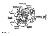
- Gear change is operated when a gear shift cam 5, which is rotated due to the shift operation by a driver of the motorcycle, sequentially changes its shift position by rotating in steps to the forward direction F and the reverse direction R.
- the six-speed return-type transmission disclosed in JP-A-Hei 6-123355 has a feature that a rotation angle ⁇ 1 of the gear shift cam 5 between the first speed position and the second speed position is larger than rotation angles ⁇ 2, ⁇ 3 ... ⁇ 6 between other shift positions, and the neutral position is provided on a position rotated by half of the rotation angle ⁇ 1 between the first speed position and the second speed position. This enables easy shift change to the neutral.
- a transmission in particular electronically controlled transmission having a return-type shift pattern
- the transmission comprising: a main shaft with a plurality of first gears configured to rotate about a center of the main shaft; a drive shaft with a plurality of second gears configured to rotate about a center of the drive shaft to mesh with the plurality of first gears; a rotatable shift cam with a plurality of grooves configured to select gears among the plurality of first and second gears for torque transmission from the main shaft to the drive shaft; and a control device configured to control rotation of the shift cam, wherein a plurality of shift steps of the transmission is set in accordance with at least a shape of the plurality of grooves, and a neutral position of the transmission is set below a lowest step of the shift steps.
- a rotation angle of the shift cam between the neutral position and the lowest step is different from that between any adjacent shift steps.
- the shift cam has an axis parallel to any of the axes of the main shaft and the drive shaft.
- a plurality of shift forks is configured to move any of the plurality of first gears in axial direction of the main shaft and to move any of the plurality of second gears in axial direction of the drive shaft, and, preferably, a plurality of fork shafts is configured to support the plurality of shift forks.
- a shift actuator is configured to rotate the shift cam
- the control device is configured to control the shift actuator
- the neutral position is set to a position rotated by 30 degrees from the lowest step of the shift steps.
- a stopper means is configured to prevent the shift cam from rotating between the neutral position and a highest step, of the shift steps.
- the stopper means comprises the shift cam, and, preferably, the stopper means is a stopper portion formed such that at least one portion between the neutral position and the highest step of the shift steps is discontinuous.
- the stopper portion is a barrier that is configured to regulate moving of at least one of the plurality of shift forks on the shift cam.
- the stopper means comprises the control device being configured to execute prevention control for preventing the shift cam from rotating between the neutral position and the highest step of the shift steps.
- the transmission comprises a clutch and a clutch actuator configured to connect or disconnect the clutch, and, preferably, the prevention control by the stopper means comprises control of the clutch actuator.
- the prevention control by the stopper means comprises control of the shift actuator.
- straddle type vehicle comprising a transmission, in particular an electronically controlled transmission, according to one of the above embodiments.
- FIG. 1 is a left side view of a motorcycle 1 according to a first embodiment.
- the outline configuration of the motorcycle 1 will be explained.
- the directions such as the front, the rear, the left, and the right refer to directions viewed by a rider sitting on a seat 9.
- the technical teaching relates to a straddle-type vehicle having a body frame and a seat on which a rider can be seated straddling the body frame when being seated.
- the motorcycle 1 includes a body frame 2.
- the body frame 2 has a head pipe 2a.
- a handlebar 3 is mounted on an upper end of the head pipe 2a, and a front wheel 7F is mounted to a lower end of the head pipe 2a through front forks 4 in a freely rotatable manner.
- a swing arm 6 is swingably attached to a rear end of the body frame 2.
- a rear wheel 7R is mounted for rotation to the rear end of the swing arm 6.
- the reference numeral 8 denotes a fuel tank.
- the seat 9 is provided at the rear side of the fuel tank 8.
- a power unit 10 including an engine 12 as a driving source is suspended from the body frame 2.
- the power unit 10 is connected to the rear wheel 7R through a power transmission means 11 such as a chain, a belt, and a drive shaft. This allows the power transmission means 11 to transmit driving force to the rear wheel 7R, the driving force being generated in the power unit 10 by the engine 12.
- a clutch 14 is a multi-plate friction clutch and includes a cylindrical clutch housing 31, a cylindrical clutch boss 32, a plurality of friction plates 33 and clutch plates 34 serving as friction plates, and a pressure plate 35. Moreover, the clutch 14 includes a gear 29 to mesh with a gear 21 a formed on a crankshaft 21 of the engine 12. Additionally, the clutch 14 is an example to be used in this embodiment, and not limited to a multi-plate clutch. For example, the clutch 14 may be an automatic centrifuge clutch using a centrifuge weight.
- the clutch housing 31 is formed in the shape of a cylinder and mounted to a main shaft 22 in a relatively rotatable manner. On an inner peripheral surface of the clutch housing 31, a plurality of grooves extending in the axial direction of the main shaft 22 are formed.
- Each friction plate 33 is formed in the shape of a thin-plate ring.
- a plurality of teeth are formed on the outer periphery of each friction plate 33. Engagement between the plural teeth formed on the outer periphery of the friction plate 33 and the plural grooves formed on the inner peripheral surface of the clutch housing 31 enables each friction plate 33 to be mounted to the clutch housing 31 in a relatively unrotatable manner. Additionally, each friction plate 33 is mounted in a slidable manner in the axial direction of the main shaft 22 with respect to the clutch housing 31.
- the clutch boss 32 is formed in the shape of a cylinder and disposed at inner side in the radial direction of the main shaft 22 compared to the clutch housing 31. Moreover, the clutch boss 32 is mounted to the main shaft 22 in a relatively unrotatable manner. On an outer peripheral surface of the clutch boss 32, a plurality of grooves extending in the axial direction of the main shaft 22 are formed.
- Each clutch plate 34 is formed in the shape of a thin-plate ring.
- a plurality of teeth are formed on the inner periphery of each clutch plate 34. Engagement between the plural teeth formed on the inner periphery of the clutch plate 34 and the plural grooves formed on the outer peripheral surface of the clutch boss 32 allows each clutch plate 34 to be mounted to the clutch boss 32 in a relatively unrotatable manner. Additionally, each clutch plate 34 is mounted in a slidable manner in the axial direction of the main shaft 22 with respect to the clutch boss 32.
- Each friction plate 33 is mounted to the clutch housing 31 such that its plate surface is substantially perpendicular to the axial direction of the main shaft 22.
- Each clutch plate 34 is mounted to the clutch boss 32 such that its plate surface is substantially perpendicular to the axial direction of the main shaft 22.
- Each friction plate 33 and each clutch plate 34 are alternately disposed in the axial direction of the main shaft 22.
- the pressure plate 35 is formed substantially in the shape of a disc and mounted in a slidable manner in the axial direction of the main shaft 22 with respect to the clutch boss 32.
- the pressure plate 35 is mounted in a freely rotatable manner to one end of a push rod 37 (the right side in FIG. 2 ), which is disposed in the cylindrical main shaft 22, through a bearing 36 such as a ball bearing.
- a spherical ball 40 adjacent to the other end of the push rod 37 (the left end) is provided in the cylindrical main shaft 22 .
- a push rod 39 adjacent to the ball 40 is provided on the left side of the ball 40.
- One end of the push rod 39 protrudes from the other end of the cylindrical main shaft 22 (the left end).
- the protruding one end of the push rod 39 is connected to a clutch actuator 18 through a clutch power transmission means 17.
- a transmission 13 is a multistep transmission and includes the main shaft 22, a drive shaft 23, and a gear selection mechanism 24.
- the main shaft 22 is connected to the crankshaft 21 of the engine through the clutch 14.
- the main shaft 22 and the drive shaft 23 are disposed substantially parallel to each other.
- a plurality of gears 25 are mounted on the main shaft 22.
- a plurality of gears 26 are mounted on the drive shaft 23 to correspond to the gears 25. Engagement between the plurality of gears 25 and the plurality of gears 26 is achieved only through a pair of selected gears.
- the plurality of gears 25 and 26 at least either the gears 25 except the selected gear 25 or the gears 26 except the selected gear 26 are rotatable with respect to the main shaft 22 or the drive shaft 23. In other words, at least either the unselected gears 25 or the unselected gears 26 idle with respect to the main shaft 22 or the drive shaft 23. Thus, rotation transmission between the main shaft 22 and the drive shaft 23 is achieved only through the selected gears 25 and 26 which engage with each other.
- a shift cam 27 of the gear selection mechanism 24 performs the selection of the gears 25 and 26.
- Cam grooves 27a, 27b, and 27c are formed on the outer peripheral surface of the shift cam 27.
- Shift forks 28a, 28b, and 28c are mounted to the cam grooves 27a, 27b, and 27c, respectively.
- Each of the shift forks respectively engages with the gear 25 and the gear 26 to form a predetermined dog of the main shaft 22 and the drive shaft 23.
- each of the plural shift forks 28a, 28b, and 28c is guided with the cam grooves 27a, 27b, and 27c to move in the axial direction of the main shaft 22 and the drive shaft 23.
- Each of the plural shift forks 28a, 28b, and 28c which are moved in the axial direction of the main shaft 22 and the drive shaft 23, engages or disengages the dog of the gears 25 and 26. This allows for selection of a fixed gear and a slide gear to engage with each other among the gears 25 and 26.
- the shift actuator 16 and the clutch actuator 18 are each connected to a control device (ECU: Electronic Control Unit) 100 to be driven by the control device 100.
- ECU Electronic Control Unit
- the control device 100 starts shift control. Initially, as shown in FIG. 2 , the control device 100 drives the clutch actuator 18 and disengages the clutch 14 to have a disengaged state. Next, the control device 100 drives the shift actuator 16 to cause the gear selection mechanism 24 to select the desired gears 25 and 26. Thereafter, the control device 100 drives the clutch actuator 18 again to engage the clutch 14.
- the gear selection mechanism 24 is connected to a shift actuator 16 through a shift power transmission mechanism 15. This allows the shift actuator 16 to drive the gear selection mechanism 24.
- the transmission 13 is a so-called constant-mesh dog transmission.
- a fixed gear 48 in the gear 25 is coupled to the main shaft 22. Engagement between the main shaft 22 and the fixed gear 48 is achieved, for example, by serrations provided on the main shaft 22 and the fixed gear 48.
- a fixed gear 47 is directly formed on the main shaft 22 as a tooth of a gear. That is, the fixed gears 47 and 48 rotate with the main shaft 22 and do not rotate relatively with respect to the main shaft 22.
- slide gears 550 and 560 are fitted to the main shaft 22, and slide gears 513 and 524 are fitted to the drive shaft 23.
- the slide gears 550 and 560 are fitted to the main shaft 22 by serrations, and the slide gears 513 and 524 are fitted to the drive shaft 23 by serrations. That is, the slide gears 550 and 560 rotate with the main shaft 22 and do not rotate relatively with respect to the main shaft 22.
- the slide gears 513 and 524 rotate with the drive shaft 23 and do not rotate relatively with respect to the drive shaft 23.
- a first speed gear 41, a second speed gear 42, a third speed gear 43, and a fourth speed gear 44 of the gear 26 engage with the drive shaft 23 via a bearing etc. That is, the first speed gear 41, the second speed gear 42, the third speed gear 43, and the fourth speed gear 44 idle with respect to the drive shaft 23.
- a fifth speed gear 45 and a sixth speed gear 46 engage with the main shaft 22 via a bearing etc. That is, the fifth speed gear 45 and the sixth speed gear 46 idle with respect to the main shaft 22.
- the first speed gear 41, the second speed gear 42, the third speed gear 43, the fourth speed gear 44, the fifth speed gear 45, and the sixth speed gear 46 are respectively provided with dogs 61, 62, 63, 64, 65, and 66 to obtain the spline fitted with a specified slide gear.
- FIG. 4A shows a state that the transmission 13 is in a neutral position.
- the rotational force of the main shaft 22 is not transmitted to the drive shaft 23.
- the torque transmission from the main shaft 22 to the drive shaft 23 is not executed even though the gear 25 and the gear 26 are in a constant-mesh state.
- the fixed gear 47 meshes with the first speed gear 41.
- the first speed gear 41 idles with respect to the drive shaft 23
- the torque transmission from the main shaft 22 to the drive shaft 23 is not executed.
- the fifth speed gear 45 meshes with the slide gear 513.
- the shift cam 27 rotates by a designated angle in the F direction, the shift fork 28a moves on the axial circumference of the shift cam 27 along the cam groove 27a formed on the shift cam 27.
- the shift fork 28a which moves on the axial circumference of the shift cam 27, moves on the fork shaft 38d in the axial direction, resulting that it moves on the drive shaft 23 by a designated distance in the axial direction. Since the shift fork 28a moves on the fork shaft 38d (the drive shaft 23) in the axial direction, the spline fit is achieved between the slide gear 513 and the dog 61.
- the slide gear 513 rotates with the drive gear 23. This allows the torque transmission from the main shaft 22 to the drive shaft 23 via the fixed gear 47 and the first speed gear 41.
- the shift cam 27 rotates by a designated angle in the F direction, and the shift fork 28a moves on the axial circumference of the shift cam 27 along the cam groove 27a formed on the shift cam 27.
- the shift fork 28a which moves on the axial circumference of the shift cam 27, moves by a specified distance in a reverse direction with respect to a position of the first speed gear 41 in the axial direction of the drive shaft 23. This disconnects the spline fit between the slide gear 513 and the dog 61.
- the shift fork 28c moves on the axial circumference of the shift cam 27 along the cam groove 27c formed on the shift cam 27.
- the shift fork 28c which moves on the axial circumference of the shift cam 27, moves on the fork shaft 38d in the axial direction, resulting that it moves on the drive shaft 23 by a specified distance in the axial direction. Since the shift fork 28c moves on the fork shaft 38d (the drive shaft 23) in the axial direction, the spline fit is achieved between the slide gear 524 and the dog 62.
- the slide gear 524 rotates with the drive gear 23. This allows the torque transmission from the main shaft 22 to the drive shaft 23 via the fixed gear 48 and the second speed gear 42.
- each shift position from the first speed to the sixth speed provided on the cam grooves of the shift cam 27 is set for 60 degrees along the axial circumference of the shift cam 27.
- a gear in/gear out operation of each shift fork in the upshift and the downshift is executed by the rotation of the shift cam 27 for 30 degrees. More specifically, when the shift fork 28a disconnects the serration fit from a position of serration fit between the slide gear 513 and the dog 61, the shift cam 27 is rotated by 30 degrees in the F direction. Thereafter, when the shift fork 28c executes serration fit between the slide gear 524 and the dog 62, the shift cam 27 rotates by 30 degrees in the F direction.
- the neutral position is a position rotated from the first speed position by 30 degrees in the R direction. Since the transmission 13 is a return-type transmission, the neutral position and the sixth speed position are discontinuous. As shown in FiGs. 4B , 5B , and 6B , the cam groove 27b has a sixth speed position misaligned with the neutral position in the axial direction of the shift cam 27. A discontinuous portion of the cam groove 27b is referred to as a stopper portion for the sake of convenience. This stopper portion prevents the shift cam 27 from rotating in the F direction even when the shift actuator 16 rotates the shift cam 27 in the F direction from the sixth speed position.
- means that prevents the shift cam 27 from rotating in the F direction from the sixth speed position even when the shift cam 27 is operated to rotate in the F direction is not limited to misalignment of the sixth speed position and the neutral position in the cam groove 27b.
- the sixth speed position and the neutral position may be misaligned in the cam groove 27a.
- the sixth speed position and the neutral position may be misaligned in the cam groove 27c.
- regulation of moving of the shift fork 28b between the neutral position and the sixth speed position is not limited to discontinuity in any of the cam grooves.
- a barrier as a stopper member may be provided on the shift cam 27 even when the cam grooves 27a, 27b, and 27c are continuous. In such a case, any of the shift forks is compulsory prevented from moving between the sixth speed position and the neutral position by the stopper member provided on the axis of the shift cam 27.
- regulation of moving of the shift fork 28b between the neutral position and the sixth speed position is not limited to the shape of a surface of the shift cam 27.
- the control device 100 may not output a drive command to the shift actuator 16 or the clutch actuator 18 and may cancel the rider's wrong command.
- the control device 100 may not output a drive command to the shift actuator 16 or the clutch actuator 18 and may cancel the riders wrong command.
- a combination of the above discussed stopper means for prevention of the rotation of the shift cam 27 between the neutral position and the highest step is possible.
- the shift cam 27 rotates in accordance with the operation of the shift actuator 16.
- a structure concerning the rotation of the shift cam 27 will be explained.
- the shift actuator 16 when the shift actuator 16 is operated, the drive force of the shift actuator 16 is transmitted to a shift shaft 51 via the shift power transmission mechanism 15.
- the shift shaft 51 is a shaft that provides the rotational force that leads to the rotation about the axis to the shift cam 27.
- a shift change command from the rider allows the shift actuator 16 to execute a specified drive to rotate the shift shaft 51 in a designated direction.
- the designated direction varies to be opposite in the upshift change or the downshift change.
- a feed device 50 is provided on one end of the shift cam 27.
- the feed device 50 is a mechanism that rotates the shift cam 27 at a designated angle utilizing the rotational force of the shift shaft 51 that rotates by the drive of the shift actuator 16.
- the feed device 50 is disposed on a case 70.
- the case 70 is disposed on the right end of the shift cam 27 to regulate the axial position of the shift cam 27.
- a plurality of holes are formed in the case 70. Among the plural holes, the shift cam 27 passes through one hole and the shift shaft 51 passes through another hole. Due to the rotation of the shift shaft 51, a shift arm 52 is rotated. For example, in an upshift operation, as shown in FIG. 3A , the shift arm 52 rotates counterclockwise.
- the shift arm 52 has a center C1 of the shift shaft 51 as the rotational center.
- a base 91 is a lid having a function of regulating an axial position of the shift cam 27 with respect to the shift shaft 51 etc.
- the base 91 is fixed in an inner portion of the case 70 by a bolt 80.
- a ball bearing 92 is provided on the inner side (the left side of FIG. 2 ) of the base 91 and the shift cam 27 is fitted to the ball bearing 92. This allows the shift cam 27 to stably rotate about a center C2.
- the rotation of the shift shaft 51 and the shift arm 52 is urged to return to a designated neutral position before rotating by a return spring 53 provided on the rear side (the left side of Fig. 2 ) of the shift arm 52.
- the return spring 53 constantly abuts to a stopper pin 56 by a left side portion 53a or a right side portion 53b and urges the shift shaft 51 and the shift arm 52 such that they return to the designated neutral position before rotating.
- the left side portion 53a of the return spring 53 of FIG. 3A is separated from the stopper pin 56 to make a clearance.
- the left side portion 53a of the return spring 53 attempts to abut against the stopper pin 56, so that the shift shaft 51 and the shift arm 52 are returned to the designated neutral position before rotating.
- a claw 54 is provided on one end (the left end of FIG. 3A ) of the shift arm 52.
- the claw 54 is provided with pin holes 54a and 54b.
- the claw 54 and the shift arm 52 are integrally formed.
- the claw 54 rotates about the center C1 of the shift shaft 51 as the rotational center in accordance with the rotation of the shift arm 52.
- the claw 54 rotates a segment 55 in response to the rotation of the shift arm 52.
- the segment 55 rotates about the center C2 of the shift cam 27 as the rotational center.
- the segment 55 has a plurality of pins 55d on its surface (see FIG. 3B ). In this embodiment, six pins 55d are provided.
- the shift shaft 51 and the shift arm 52 are positioned at the designated neutral position before rotating, two adjacent pins 55d are respectively covered by the pin hole 54a or the pin hole 54b.
- the pin hole 54b holds one pin 55d to rotate the segment 55 in the counterclockwise direction.
- one pin 55d is covered by the claw 54 in a position where a curved surface 55c of the claw 54 abuts to a stopper bearing 90.
- the segment 55 is in the shape of a star configured by superimposing two triangles.
- a position of each depression 55b is an enter position of each gear of the shift cam 27.
- the transmission 13 is a six-speed transmission, and the neutral position is below the first speed position. Because of this, in the depressions 55b of the segment 55, starting from the first speed, the second speed, the third speed ... and the sixth speed are sequentially provided in the clockwise direction.
- the neutral position of the segment 55 is the curved surface 55c which is a projection between the sixth speed and the first speed with a height intermediate between the projection 55a and the depression 55b.
- the feed device 50 includes a stopper spring 57.
- the stopper spring 57 has one end supported by a pin 58 provided in the feed device 50 and the other end for supporting a stopper lever 59.
- the stopper spring 57 is a coil spring.
- the stopper spring 57 is connected to the pin 58 and the stopper lever 59 in a tension state of the spring.
- the stopper lever 59 is provided on the back side (the left side of FIG. 2 ) of the shift arm 52 in FIG. 3A to rotate about the center C1 of the shift arm 52. Because of this, the stopper spring 57 allows the stopper bearing 90 to constantly abut to the segment 55 by an urging force of the spring in a compressing direction. Since the stopper bearing 90 receiving the urging force of the stopper spring 57 abuts to the segment 55, the segment 55 can stably rotate about the center C2 of the shift cam 27 in response to the operation of the claw 54.
- a shift cam potentiometer 93 is provided on the opposite side of the feed device 50 across the shift cam 27.
- the shift cam potentiometer 93 monitors so that the rotation angle of the shift cam 27 does not exceed a designated angle provided by the control device 100.
- the transmission 13 preferably is a return-type electronically controlled transmission, wherein preferably the shift cam 27 can be rotated in forward and reverse directions.
- the neutral position is so-called bottom neutral and set below the first speed position. This allows the transmission 13 to have a clear distinction in terms of positional relationship between the neutral position and positions of other shift steps compared to a case where the neutral position is provided between the first speed and the second speed.
- the neutral position of the transmission 13 is set on a rotation angle of the shift cam 27 which is different from the rotation angle of other shift steps excluding the neutral position. Because of this, also in the control by the control device 100, the shift operation to the neutral position has a clear distinction in terms of numerical values compared to other shift steps. This allows the transmission 13 to execute the shifting to the neutral position accurately. Consequently, it is possible to provide a return-type electronically controlled transmission capable of shifting to the neutral reliably.
- shift steps excluding the neutral position are provided by a constant rotation angle of the shift cam 27.
- the shift cam 27 can be rotated by a constant driving force compared to a case where the shift steps are not provided at even internals.
- the shift operation to the neutral position has a more explicit distinction in terms of numerical values compared to other shift steps. This allows the transmission 13 to execute the shifting to the neutral position easily and accurately in terms of control. Consequently, it is possible to execute a reliable shifting to the neutral position.
- the transmission 13 according to the embodiment is a six-speed transmission.
- a reduction ratio which is more appropriate or smaller can be obtained. Because of this, when the transmission 13 is used in an actual machine such as a vehicle, an efficient driving can be executed through an appropriate reduction ratio.
- gear selection in accordance with the running state can be appropriately conducted when the motorcycle 1 is running.
- the rotation angles of the shift cam 27 from the first speed to the sixth speed are set to be 60 degrees. Because of this, a rotation angle of the shift cam 27 to each shift step is constant while the entire axial circumference of the shift cam 27 is effectively utilized. For example, when each shift step from the first speed to the sixth speed is set for 50 degrees, moving distance of the shift fork 28 during the rotation of the shift cam 27 by 50 degrees is increased compared to a case where each shift step is set for 60 degrees. This increases the driving force necessary for the rotation of the shift cam 27. As a result, the transmission 13 can be constituted as a transmission with a reduced driving force to considering extend necessary for the shift operation while utilizing the shift cam 27 effectively.
- the neutral position of the transmission 13 is set to be a position rotated by 30 degrees below the first speed or a position rotated by 30 degrees above the sixth speed. That is, the neutral position is provided at 30 degree intervals between the first speed and the sixth speed (see FIG. 3C ).
- a rotation angle of the shift cam 27 necessary for the shift change to each shift step is set to be half for a gear in/gear out operation.
- a moving distance of the shift fork 28 in the axial direction of the shift cam 27 with respect to each slide gear is set to be half for a gear in/gear out operation.
- each shift fork for a gear in/gear out operation is executed by the rotation of the shift cam 27 for 30 degrees. Accordingly, in a shift operation to the neutral position of the transmission 13, the moving operation of the shift fork 28a on the shift cam 27 closely resembles the moving operation of each shift fork on the shift cam 27 in a gear out operation even though the direction may be reversed in the axial direction of the shift cam 27. Consequently, it is possible to execute a reliable shifting to the neutral position.
- the transmission 13 in the embodiment is so-called bottom neutral.
- the transmission 13 includes stopper means that prevents the moving between the neutral position and the highest step of the shift steps. This allows for a reliable shifting to the neutral position.
- the shifting to the lowest step of the shift steps can be smoothly executed in a gear in operation since the shift direction from the neutral position is limited to the lowest step of the shift steps.
- the stopper means is the stopper portion configured by making the cam groove 27b discontinuous. This stopper portion avoids an additional step of providing another stopper means instead of the stopper portion in the fabrication of the shift cam 27 and the like. Consequently, the stopper means effective as described above can be easily provided. As a result, the return-type electronically controlled transmission capable of shifting to the neutral reliably can be provided.
- the stopper means may be provided on the shift cam 27 as the stopper member.
- the stopper member is a barrier formed on the shift cam 27 so that at least one portion between the neutral position and the sixth speed is discontinuous. In such a case, it is unnecessary to secure an additional space compared to a case where another barrier instead of the stopper member is provided on a portion other than the shift cam 27. Consequently, the stopper means effective as described above can be easily provided. As a result, the return-type electronically controlled transmission capable of shifting to the neutral reliably can be provided.
- the transmission 13 in the embodiment includes the clutch actuator 18 for operating the clutch 14, the shift actuator 16 for rotating the shift cam 27, and the control device 100 for controlling the operation of the clutch actuator 18 and the shift actuator 16. Consequently, in the transmission 13, the moving between the neutral position and the highest step of the shift steps is regulated due to the control by the control device 100. As a result, the return-type electronically controlled transmission capable of shifting to the neutral reliably can be provided.
- the transmission 13 is provided with the motorcycle 1 which is a straddle type vehicle.
- the transmission 13 is the return-type electronically controlled transmission, and the so-called bottom neutral transmission where the neutral position is located below the lowest step of the shift steps.
- the shifting to the neutral position by mistake would not occur, while the shifting to the neutral position can be reliably executed.
- the straddle type vehicle having the return-type electronically controlled transmission capable of shifting to the neutral reliably.
- the present teaching is effective for an electronically controlled transmission and a straddle type vehicle having the same.
- an electronically controlled transmission having a return-type shift pattern connected to a crank shaft of an engine via a clutch
- the transmission comprising: a main shaft disposed parallel to the crank shaft for rotating in accordance with rotation of the crank shaft via the clutch; a drive shaft disposed parallel to the main shaft for rotating in accordance with rotation of the main shaft; a plurality of first gears for rotating about the center of the main shaft; a plurality of second gears for rotating about the center of the drive shaft to mesh with the plurality of first gears; a plurality of shift forks for moving any of the plurality of first gears in the axial direction of the main shaft and moving any of the plurality of second gears in the axial direction of the drive shaft; a plurality of fork shafts for supporting the plurality of shift forks; a shift cam having an axis parallel to any of the main shaft and the drive shaft and provided with a plurality of grooves that execute a designated rotation about the axis; a clutch actuator
- the number of the shift steps are set by rotation angles having even intervals in the shift cam.
- the number of the shift steps are set from the first speed to the sixth speed.
- the number of the shift steps are set for a rotation angle of 60 degrees in the shift cam.
- the neutral position is set to a position rotated by 30 degrees from the first speed of the shift steps.
- the electronically controlled transmission further comprises stopper means that prevents the shift cam from rotating between the neutral position and the highest step of the shift steps.
- the stopper means is provided on the shift cam, and the stopper means is a stopper portion formed so that at least one portion between the neutral position and the highest step of the shift steps is discontinuous.
- the stopper portion is a barrier that regulates moving of one of the plurality of shift forks on the shift cam.
- the stopper means is constituted by control of the control device that executes prevention control for preventing the shift cam from rotating between the neutral position and the highest step of the shift steps.
- the prevention control is control for the clutch actuator.
- the prevention control is control for the shift actuator.
- an embodiment of a straddle type vehicle comprises the electronically controlled transmission according to one of the preceding embodiments.
- an embodiment of a transmission 13 includes: a main shaft 22; a drive shaft 23 for rotating in accordance with rotation of the main shaft 22; a gear 25; a gear 26; a plurality of shift forks 28; a plurality of fork shafts 38; a shift cam 27 in which a plurality of grooves that execute a designated rotation about the center are formed; a clutch actuator 18; a shift actuator 16; and a control device 100 for controlling the clutch actuator 18 and the shift actuator 16.
- a plurality of shift steps concerning the transmission 13 are set in accordance with at least a shape of the plurality of grooves, a neutral position of the transmission 13 is set below the lowest step of the shift steps, and a rotation angle of the shift cam between the neutral position and the lowest step is different from that between any adjacent shift steps.
Abstract
Description
- The present invention relates to a transmission, in particular an electronically controlled transmission, and in particular to a straddle type vehicle having the same.
- The prior art document
EP 0 573 901 A1 teaches a respective transmission having a main shaft with a plurality of first gears configured to rotate about a center of the main shaft and a drive shaft with a plurality of second gears configured to rotate about a center of the drive shaft to mesh with the plurality of first gears. Said prior art document discloses a transmission having five gear steps in combination with a neutral position, wherein a rotatable shift cam is provided with three grooves configured to select respective gears among the plurality of the first and second gears for torque transmission from the main shaft to the drive shaft. The respective control device is configured to control rotation of the shift cam, wherein a plurality of shift steps of the transmission is set in accordance with at least a shape of the plurality of grooves, and the neutral position of the transmission is set below the lowest step of the shift steps. Within said prior art document, the grooves along the rotatable shift cam are arranged on a restricted area of the same, so that a short distance between the lowest step and the fifth step, as well as between the intermediate steps, can be ensured. -
EP 2 085 665 A1 - The further prior art document
WO 00/73679 A1 - Conventionally, a mechanism of a return-type transmission includes a transmission as disclosed in
JP-A-Hei 6-123355 FIG. 7 , the return-type transmission disclosed inJP-A-Hei 6-123355 gear shift cam 5, which is rotated due to the shift operation by a driver of the motorcycle, sequentially changes its shift position by rotating in steps to the forward direction F and the reverse direction R. The six-speed return-type transmission disclosed inJP-A-Hei 6-123355 gear shift cam 5 between the first speed position and the second speed position is larger than rotation angles θ2, θ3 ... θ6 between other shift positions, and the neutral position is provided on a position rotated by half of the rotation angle θ1 between the first speed position and the second speed position. This enables easy shift change to the neutral. - However, when the neutral position is provided between the first speed and the second speed, shifting from the first speed to the neutral or from the second speed to the neutral could occur during running of the vehicle. Moreover, in a case where a shift change from the first speed to the neutral is intended when the vehicle is stopped, shifting to the second speed by skipping over the neutral could occur, so that the shifting between the first speed and the second speed could occur. In a so-called AMT (Automated Manual Transmission) which is an electronically controlled transmission with the shift operation using an actuator instead of manual operation, these situations are undesirable as the shift operation is not directly executed by the driver of the motorcycle. This is because, in the AMT, a correct and smooth automatic control in shifting is desired rather than the driver's operation. The present invention is made in view of the above problems.
- It is an object of the present invention to provide a transmission as indicated above, which allows high operation performance as well as reliable shifting to the neutral position.
- According to the present invention, said objective is solved by a transmission having the features of independent claim 1. Preferred embodiments are laid down in the dependent claims.
- Accordingly, it is provided a transmission, in particular electronically controlled transmission having a return-type shift pattern, the transmission comprising: a main shaft with a plurality of first gears configured to rotate about a center of the main shaft; a drive shaft with a plurality of second gears configured to rotate about a center of the drive shaft to mesh with the plurality of first gears; a rotatable shift cam with a plurality of grooves configured to select gears among the plurality of first and second gears for torque transmission from the main shaft to the drive shaft; and a control device configured to control rotation of the shift cam, wherein a plurality of shift steps of the transmission is set in accordance with at least a shape of the plurality of grooves, and a neutral position of the transmission is set below a lowest step of the shift steps.
- According to the above, it is possible to provide a return-type electronically controlled transmission capable of shifting to neutral reliably.
- Preferably, a rotation angle of the shift cam between the neutral position and the lowest step is different from that between any adjacent shift steps.
- Further, preferably the shift cam has an axis parallel to any of the axes of the main shaft and the drive shaft.
- According to a preferred embodiment, a plurality of shift forks is configured to move any of the plurality of first gears in axial direction of the main shaft and to move any of the plurality of second gears in axial direction of the drive shaft, and, preferably, a plurality of fork shafts is configured to support the plurality of shift forks.
- Preferably, a shift actuator is configured to rotate the shift cam, and the control device is configured to control the shift actuator.
- Yet further still, preferably the neutral position is set to a position rotated by 30 degrees from the lowest step of the shift steps.
- According to another preferred embodiment, a stopper means is configured to prevent the shift cam from rotating between the neutral position and a highest step, of the shift steps.
- Preferably, the stopper means comprises the shift cam, and, preferably, the stopper means is a stopper portion formed such that at least one portion between the neutral position and the highest step of the shift steps is discontinuous.
- Further, preferably the stopper portion is a barrier that is configured to regulate moving of at least one of the plurality of shift forks on the shift cam.
- Still further, preferably the stopper means comprises the control device being configured to execute prevention control for preventing the shift cam from rotating between the neutral position and the highest step of the shift steps.
- Preferably, the transmission comprises a clutch and a clutch actuator configured to connect or disconnect the clutch, and, preferably, the prevention control by the stopper means comprises control of the clutch actuator.
- Further, preferably the prevention control by the stopper means comprises control of the shift actuator.
- There is further provided a straddle type vehicle comprising a transmission, in particular an electronically controlled transmission, according to one of the above embodiments.
- In the following, the present invention is explained in greater detail by means of embodiments thereof in conjunction with the accompanying drawings, wherein:
- FIG. 1
- is a left side view of a motorcycle according to an embodiment;
- FIG.2
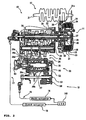
- is a drawing showing a configuration of a power unit according to the embodiment;
- FIG. 3A
- is a front view of a feed device;
- FIG. 3B
- is a front view of a part of the feed device;
- FIG. 3C
- is a front view of a segment;
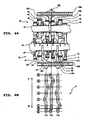
- FIGs. 4A and 4B
- are drawings showing a neutral position of a shift pattern of a transmission according to the embodiment, in which
FIG. 4A shows an entire gear selection mechanism andFIG. 4B shows cam grooves; - FIGs. 5A and 5B
- are drawings showing a first speed position of the shift pattern of the transmission according to the embodiment, in which
FIG. 5A shows the entire gear selection mechanism andFIG. 5B shows the cam grooves; - FIGs. 6A and 6B
- are drawings showing a second speed position of the shift pattern of the transmission according to the embodiment, in which
FIG. 6A shows the entire gear selection mechanism andFIG. 6B shows the cam grooves; and - FIG. 7
- is a front view showing a part of a conventional transmission.
- Among others, the following reference signs are used in the figures:
- 1: motorcycle
- 3: handlebar
- 10: power unit
- 12: engine
- 13: transmission (electronically controlled transmission)
- 14: clutch
- 16: shift actuator
- 18: clutch actuator
- 21: crankshaft
- 22: main shaft
- 23: drive shaft
- 24: gear selection mechanism
- 25: gear
- 26: gear
- 27: shift cam
- 27a: cam groove
- 27b: cam groove
- 27c: cam groove
- 28a: shift fork
- 28b: shift fork
- 28c: shift fork
- 38d: fork shaft
- 38m: fork shaft
- 50: feed device
- 51: shift shaft
- 52: shift arm
- 55: segment
- 90: stopper bearing
- 93: shift cam potentiometer
- 100: control device
-
FIG. 1 is a left side view of a motorcycle 1 according to a first embodiment. With reference toFIG. 1 , the outline configuration of the motorcycle 1 will be explained. In the following description, the directions such as the front, the rear, the left, and the right refer to directions viewed by a rider sitting on a seat 9. In particular, the technical teaching relates to a straddle-type vehicle having a body frame and a seat on which a rider can be seated straddling the body frame when being seated. - The motorcycle 1 includes a
body frame 2. Thebody frame 2 has a head pipe 2a. Ahandlebar 3 is mounted on an upper end of the head pipe 2a, and afront wheel 7F is mounted to a lower end of the head pipe 2a throughfront forks 4 in a freely rotatable manner. - A
swing arm 6 is swingably attached to a rear end of thebody frame 2. Arear wheel 7R is mounted for rotation to the rear end of theswing arm 6. - The reference numeral 8 denotes a fuel tank. The seat 9 is provided at the rear side of the fuel tank 8.
- A
power unit 10 including anengine 12 as a driving source is suspended from thebody frame 2. Thepower unit 10 is connected to therear wheel 7R through a power transmission means 11 such as a chain, a belt, and a drive shaft. This allows the power transmission means 11 to transmit driving force to therear wheel 7R, the driving force being generated in thepower unit 10 by theengine 12. - In this embodiment, a clutch 14 is a multi-plate friction clutch and includes a cylindrical
clutch housing 31, a cylindricalclutch boss 32, a plurality offriction plates 33 andclutch plates 34 serving as friction plates, and apressure plate 35. Moreover, the clutch 14 includes agear 29 to mesh with agear 21 a formed on acrankshaft 21 of theengine 12. Additionally, the clutch 14 is an example to be used in this embodiment, and not limited to a multi-plate clutch. For example, the clutch 14 may be an automatic centrifuge clutch using a centrifuge weight. - The
clutch housing 31 is formed in the shape of a cylinder and mounted to amain shaft 22 in a relatively rotatable manner. On an inner peripheral surface of theclutch housing 31, a plurality of grooves extending in the axial direction of themain shaft 22 are formed. - Each
friction plate 33 is formed in the shape of a thin-plate ring. A plurality of teeth are formed on the outer periphery of eachfriction plate 33. Engagement between the plural teeth formed on the outer periphery of thefriction plate 33 and the plural grooves formed on the inner peripheral surface of theclutch housing 31 enables eachfriction plate 33 to be mounted to theclutch housing 31 in a relatively unrotatable manner. Additionally, eachfriction plate 33 is mounted in a slidable manner in the axial direction of themain shaft 22 with respect to theclutch housing 31. - The
clutch boss 32 is formed in the shape of a cylinder and disposed at inner side in the radial direction of themain shaft 22 compared to theclutch housing 31. Moreover, theclutch boss 32 is mounted to themain shaft 22 in a relatively unrotatable manner. On an outer peripheral surface of theclutch boss 32, a plurality of grooves extending in the axial direction of themain shaft 22 are formed. - Each
clutch plate 34 is formed in the shape of a thin-plate ring. A plurality of teeth are formed on the inner periphery of eachclutch plate 34. Engagement between the plural teeth formed on the inner periphery of theclutch plate 34 and the plural grooves formed on the outer peripheral surface of theclutch boss 32 allows eachclutch plate 34 to be mounted to theclutch boss 32 in a relatively unrotatable manner. Additionally, eachclutch plate 34 is mounted in a slidable manner in the axial direction of themain shaft 22 with respect to theclutch boss 32. - Each
friction plate 33 is mounted to theclutch housing 31 such that its plate surface is substantially perpendicular to the axial direction of themain shaft 22. Eachclutch plate 34 is mounted to theclutch boss 32 such that its plate surface is substantially perpendicular to the axial direction of themain shaft 22. Eachfriction plate 33 and eachclutch plate 34 are alternately disposed in the axial direction of themain shaft 22. - The
pressure plate 35 is formed substantially in the shape of a disc and mounted in a slidable manner in the axial direction of themain shaft 22 with respect to theclutch boss 32. Thepressure plate 35 is mounted in a freely rotatable manner to one end of a push rod 37 (the right side inFIG. 2 ), which is disposed in the cylindricalmain shaft 22, through abearing 36 such as a ball bearing. - In the cylindrical
main shaft 22, aspherical ball 40 adjacent to the other end of the push rod 37 (the left end) is provided. On the left side of theball 40, apush rod 39 adjacent to theball 40 is provided. - One end of the push rod 39 (the left end) protrudes from the other end of the cylindrical main shaft 22 (the left end). The protruding one end of the
push rod 39 is connected to aclutch actuator 18 through a clutch power transmission means 17. - A
transmission 13 is a multistep transmission and includes themain shaft 22, adrive shaft 23, and agear selection mechanism 24. Themain shaft 22 is connected to thecrankshaft 21 of the engine through the clutch 14. Themain shaft 22 and thedrive shaft 23 are disposed substantially parallel to each other. - A plurality of
gears 25 are mounted on themain shaft 22. On the other hand, a plurality ofgears 26 are mounted on thedrive shaft 23 to correspond to thegears 25. Engagement between the plurality ofgears 25 and the plurality ofgears 26 is achieved only through a pair of selected gears. Among the plurality ofgears gears 25 except the selectedgear 25 or thegears 26 except the selectedgear 26 are rotatable with respect to themain shaft 22 or thedrive shaft 23. In other words, at least either the unselected gears 25 or the unselected gears 26 idle with respect to themain shaft 22 or thedrive shaft 23. Thus, rotation transmission between themain shaft 22 and thedrive shaft 23 is achieved only through the selected gears 25 and 26 which engage with each other. - Selection of the
gears gear selection mechanism 24. More specifically, as shown inFIG. 4 , ashift cam 27 of thegear selection mechanism 24 performs the selection of thegears Cam grooves shift cam 27.Shift forks cam grooves gear 25 and thegear 26 to form a predetermined dog of themain shaft 22 and thedrive shaft 23. When theshift cam 27 is rotated, each of theplural shift forks cam grooves main shaft 22 and thedrive shaft 23. Each of theplural shift forks main shaft 22 and thedrive shaft 23, engages or disengages the dog of thegears gears gears shift cam 27 is fixed by a spline via the dog with respect to themain shaft 22 and thedrive shaft 23. This determines a position of the gears, and through thegears main shaft 22 and thedrive shaft 23. - The
shift actuator 16 and theclutch actuator 18 are each connected to a control device (ECU: Electronic Control Unit) 100 to be driven by thecontrol device 100. - Specifically, when a rider inputs a shift change command in an input device, the
control device 100 starts shift control. Initially, as shown inFIG. 2 , thecontrol device 100 drives theclutch actuator 18 and disengages the clutch 14 to have a disengaged state. Next, thecontrol device 100 drives theshift actuator 16 to cause thegear selection mechanism 24 to select the desired gears 25 and 26. Thereafter, thecontrol device 100 drives theclutch actuator 18 again to engage the clutch 14. - The
gear selection mechanism 24 is connected to ashift actuator 16 through a shiftpower transmission mechanism 15. This allows theshift actuator 16 to drive thegear selection mechanism 24. - Hereinafter, a state of shift change concerning the
transmission 13 will be explained in detail using the drawings. - The
transmission 13 is a so-called constant-mesh dog transmission. InFIGs. 4 ,5 , and6 , a fixedgear 48 in thegear 25 is coupled to themain shaft 22. Engagement between themain shaft 22 and the fixedgear 48 is achieved, for example, by serrations provided on themain shaft 22 and the fixedgear 48. In addition, a fixedgear 47 is directly formed on themain shaft 22 as a tooth of a gear. That is, the fixed gears 47 and 48 rotate with themain shaft 22 and do not rotate relatively with respect to themain shaft 22. Moreover, slide gears 550 and 560 are fitted to themain shaft 22, and slide gears 513 and 524 are fitted to thedrive shaft 23. The slide gears 550 and 560 are fitted to themain shaft 22 by serrations, and the slide gears 513 and 524 are fitted to thedrive shaft 23 by serrations. That is, the slide gears 550 and 560 rotate with themain shaft 22 and do not rotate relatively with respect to themain shaft 22. The slide gears 513 and 524 rotate with thedrive shaft 23 and do not rotate relatively with respect to thedrive shaft 23. Moreover, afirst speed gear 41, asecond speed gear 42, athird speed gear 43, and afourth speed gear 44 of thegear 26 engage with thedrive shaft 23 via a bearing etc. That is, thefirst speed gear 41, thesecond speed gear 42, thethird speed gear 43, and thefourth speed gear 44 idle with respect to thedrive shaft 23. In addition, afifth speed gear 45 and asixth speed gear 46 engage with themain shaft 22 via a bearing etc. That is, thefifth speed gear 45 and thesixth speed gear 46 idle with respect to themain shaft 22. Thefirst speed gear 41, thesecond speed gear 42, thethird speed gear 43, thefourth speed gear 44, thefifth speed gear 45, and thesixth speed gear 46 are respectively provided withdogs -
FIG. 4A shows a state that thetransmission 13 is in a neutral position. When thetransmission 13 is in the neutral position, the rotational force of themain shaft 22 is not transmitted to thedrive shaft 23. In other words, the torque transmission from themain shaft 22 to thedrive shaft 23 is not executed even though thegear 25 and thegear 26 are in a constant-mesh state. Reviewing meshing between thegear 25 and thegear 26 in the neutral position, the fixedgear 47 meshes with thefirst speed gear 41. However, as thefirst speed gear 41 idles with respect to thedrive shaft 23, the torque transmission from themain shaft 22 to thedrive shaft 23 is not executed. Moreover, thefifth speed gear 45 meshes with theslide gear 513. However, as thefifth speed gear 45 idles with respect to themain shaft 22, the torque transmission from themain shaft 22 to thedrive shaft 23 is not executed. In a similar manner, in meshing between thegear 25 and thegear 26, the torque transmission from themain shaft 22 to thedrive shaft 23 is not executed by the gear which idles between themain shaft 22 and thedrive shaft 23. - In the neutral position to the first speed upshift, the
shift cam 27 rotates by a designated angle in the F direction, theshift fork 28a moves on the axial circumference of theshift cam 27 along thecam groove 27a formed on theshift cam 27. As shown inFIGs. 4A and5A , theshift fork 28a, which moves on the axial circumference of theshift cam 27, moves on thefork shaft 38d in the axial direction, resulting that it moves on thedrive shaft 23 by a designated distance in the axial direction. Since theshift fork 28a moves on thefork shaft 38d (the drive shaft 23) in the axial direction, the spline fit is achieved between theslide gear 513 and thedog 61. Theslide gear 513 rotates with thedrive gear 23. This allows the torque transmission from themain shaft 22 to thedrive shaft 23 via the fixedgear 47 and thefirst speed gear 41. - Then, as shown in
FIGs. 5 and6 , in the first speed to the second speed upshift, theshift cam 27 rotates by a designated angle in the F direction, and theshift fork 28a moves on the axial circumference of theshift cam 27 along thecam groove 27a formed on theshift cam 27. As shown inFIGs. 5A and6A , theshift fork 28a, which moves on the axial circumference of theshift cam 27, moves by a specified distance in a reverse direction with respect to a position of thefirst speed gear 41 in the axial direction of thedrive shaft 23. This disconnects the spline fit between theslide gear 513 and thedog 61. Moreover, as shown inFIGs. 5B and6B , theshift fork 28c moves on the axial circumference of theshift cam 27 along thecam groove 27c formed on theshift cam 27. Theshift fork 28c, which moves on the axial circumference of theshift cam 27, moves on thefork shaft 38d in the axial direction, resulting that it moves on thedrive shaft 23 by a specified distance in the axial direction. Since theshift fork 28c moves on thefork shaft 38d (the drive shaft 23) in the axial direction, the spline fit is achieved between theslide gear 524 and thedog 62. Theslide gear 524 rotates with thedrive gear 23. This allows the torque transmission from themain shaft 22 to thedrive shaft 23 via the fixedgear 48 and thesecond speed gear 42. - As shown in
FIG. 6B , each shift position from the first speed to the sixth speed provided on the cam grooves of theshift cam 27 is set for 60 degrees along the axial circumference of theshift cam 27. Moreover, a gear in/gear out operation of each shift fork in the upshift and the downshift is executed by the rotation of theshift cam 27 for 30 degrees. More specifically, when theshift fork 28a disconnects the serration fit from a position of serration fit between theslide gear 513 and thedog 61, theshift cam 27 is rotated by 30 degrees in the F direction. Thereafter, when theshift fork 28c executes serration fit between theslide gear 524 and thedog 62, theshift cam 27 rotates by 30 degrees in the F direction. - In addition, the neutral position is a position rotated from the first speed position by 30 degrees in the R direction. Since the
transmission 13 is a return-type transmission, the neutral position and the sixth speed position are discontinuous. As shown inFiGs. 4B ,5B , and6B , thecam groove 27b has a sixth speed position misaligned with the neutral position in the axial direction of theshift cam 27. A discontinuous portion of thecam groove 27b is referred to as a stopper portion for the sake of convenience. This stopper portion prevents theshift cam 27 from rotating in the F direction even when theshift actuator 16 rotates theshift cam 27 in the F direction from the sixth speed position. - However, means that prevents the
shift cam 27 from rotating in the F direction from the sixth speed position even when theshift cam 27 is operated to rotate in the F direction is not limited to misalignment of the sixth speed position and the neutral position in thecam groove 27b. For example, the sixth speed position and the neutral position may be misaligned in thecam groove 27a. Moreover, the sixth speed position and the neutral position may be misaligned in thecam groove 27c. - Moreover, regulation of moving of the
shift fork 28b between the neutral position and the sixth speed position is not limited to discontinuity in any of the cam grooves. For example, a barrier as a stopper member (not shown) may be provided on theshift cam 27 even when thecam grooves shift cam 27. - Moreover, regulation of moving of the
shift fork 28b between the neutral position and the sixth speed position is not limited to the shape of a surface of theshift cam 27. For example, in a case where the transmission is in the neutral position, when the rider inputs a downshift command in an input device by mistake, thecontrol device 100 may not output a drive command to theshift actuator 16 or theclutch actuator 18 and may cancel the rider's wrong command. On the other hand, in a case where the transmission is in the sixth speed position, when the rider inputs an upshift command in the input device by mistake, thecontrol device 100 may not output a drive command to theshift actuator 16 or theclutch actuator 18 and may cancel the riders wrong command. Also, a combination of the above discussed stopper means for prevention of the rotation of theshift cam 27 between the neutral position and the highest step is possible. - Incidentally, the
shift cam 27 rotates in accordance with the operation of theshift actuator 16. Hereinafter, a structure concerning the rotation of theshift cam 27 will be explained. - As shown in
FIG. 2 , when theshift actuator 16 is operated, the drive force of theshift actuator 16 is transmitted to ashift shaft 51 via the shiftpower transmission mechanism 15. Theshift shaft 51 is a shaft that provides the rotational force that leads to the rotation about the axis to theshift cam 27. A shift change command from the rider allows theshift actuator 16 to execute a specified drive to rotate theshift shaft 51 in a designated direction. The designated direction varies to be opposite in the upshift change or the downshift change. - A
feed device 50 is provided on one end of theshift cam 27. Thefeed device 50 is a mechanism that rotates theshift cam 27 at a designated angle utilizing the rotational force of theshift shaft 51 that rotates by the drive of theshift actuator 16. Thefeed device 50 is disposed on acase 70. InFIG. 2 , thecase 70 is disposed on the right end of theshift cam 27 to regulate the axial position of theshift cam 27. A plurality of holes (not shown) are formed in thecase 70. Among the plural holes, theshift cam 27 passes through one hole and theshift shaft 51 passes through another hole. Due to the rotation of theshift shaft 51, ashift arm 52 is rotated. For example, in an upshift operation, as shown inFIG. 3A , theshift arm 52 rotates counterclockwise. Theshift arm 52 has a center C1 of theshift shaft 51 as the rotational center. Moreover, abase 91 is a lid having a function of regulating an axial position of theshift cam 27 with respect to theshift shaft 51 etc. Thebase 91 is fixed in an inner portion of thecase 70 by abolt 80. Moreover, aball bearing 92 is provided on the inner side (the left side ofFIG. 2 ) of thebase 91 and theshift cam 27 is fitted to theball bearing 92. This allows theshift cam 27 to stably rotate about a center C2. - The rotation of the
shift shaft 51 and theshift arm 52 is urged to return to a designated neutral position before rotating by areturn spring 53 provided on the rear side (the left side ofFig. 2 ) of theshift arm 52. In other words, thereturn spring 53 constantly abuts to astopper pin 56 by aleft side portion 53a or a right side portion 53b and urges theshift shaft 51 and theshift arm 52 such that they return to the designated neutral position before rotating. For example, in a shift operation in the upshift, theleft side portion 53a of thereturn spring 53 ofFIG. 3A is separated from thestopper pin 56 to make a clearance. However, due to the urging force of thereturn spring 53, theleft side portion 53a of thereturn spring 53 attempts to abut against thestopper pin 56, so that theshift shaft 51 and theshift arm 52 are returned to the designated neutral position before rotating. - A
claw 54 is provided on one end (the left end ofFIG. 3A ) of theshift arm 52. Theclaw 54 is provided withpin holes claw 54 and theshift arm 52 are integrally formed. Theclaw 54 rotates about the center C1 of theshift shaft 51 as the rotational center in accordance with the rotation of theshift arm 52. Moreover, theclaw 54 rotates asegment 55 in response to the rotation of theshift arm 52. - The
segment 55 rotates about the center C2 of theshift cam 27 as the rotational center. Thesegment 55 has a plurality ofpins 55d on its surface (seeFIG. 3B ). In this embodiment, sixpins 55d are provided. When theshift shaft 51 and theshift arm 52 are positioned at the designated neutral position before rotating, twoadjacent pins 55d are respectively covered by thepin hole 54a or thepin hole 54b. Here, when an upshift operation is executed in thetransmission 13, in accordance with the counterclockwise rotation of theshift arm 52, thepin hole 54b holds onepin 55d to rotate thesegment 55 in the counterclockwise direction. Additionally, as described later, onepin 55d is covered by theclaw 54 in a position where acurved surface 55c of theclaw 54 abuts to astopper bearing 90. As shown inFIG. 3C , thesegment 55 is in the shape of a star configured by superimposing two triangles. When thesegment 55 is divided intoprojections 55a anddepressions 55b in consideration of its shape, a position of eachdepression 55b is an enter position of each gear of theshift cam 27. In this embodiment, thetransmission 13 is a six-speed transmission, and the neutral position is below the first speed position. Because of this, in thedepressions 55b of thesegment 55, starting from the first speed, the second speed, the third speed ... and the sixth speed are sequentially provided in the clockwise direction. The neutral position of thesegment 55 is thecurved surface 55c which is a projection between the sixth speed and the first speed with a height intermediate between theprojection 55a and thedepression 55b. - Moreover, the
feed device 50 includes astopper spring 57. Thestopper spring 57 has one end supported by apin 58 provided in thefeed device 50 and the other end for supporting astopper lever 59. For example, thestopper spring 57 is a coil spring. Thestopper spring 57 is connected to thepin 58 and thestopper lever 59 in a tension state of the spring. Thestopper lever 59 is provided on the back side (the left side ofFIG. 2 ) of theshift arm 52 inFIG. 3A to rotate about the center C1 of theshift arm 52. Because of this, thestopper spring 57 allows the stopper bearing 90 to constantly abut to thesegment 55 by an urging force of the spring in a compressing direction. Since the stopper bearing 90 receiving the urging force of thestopper spring 57 abuts to thesegment 55, thesegment 55 can stably rotate about the center C2 of theshift cam 27 in response to the operation of theclaw 54. - In addition, in
FIG. 2 , ashift cam potentiometer 93 is provided on the opposite side of thefeed device 50 across theshift cam 27. Theshift cam potentiometer 93 monitors so that the rotation angle of theshift cam 27 does not exceed a designated angle provided by thecontrol device 100. - In the embodiment, the
transmission 13 preferably is a return-type electronically controlled transmission, wherein preferably theshift cam 27 can be rotated in forward and reverse directions. In thetransmission 13, the neutral position is so-called bottom neutral and set below the first speed position. This allows thetransmission 13 to have a clear distinction in terms of positional relationship between the neutral position and positions of other shift steps compared to a case where the neutral position is provided between the first speed and the second speed. - In addition, the neutral position of the
transmission 13 is set on a rotation angle of theshift cam 27 which is different from the rotation angle of other shift steps excluding the neutral position. Because of this, also in the control by thecontrol device 100, the shift operation to the neutral position has a clear distinction in terms of numerical values compared to other shift steps. This allows thetransmission 13 to execute the shifting to the neutral position accurately. Consequently, it is possible to provide a return-type electronically controlled transmission capable of shifting to the neutral reliably. - Moreover, in the
transmission 13, other shift steps excluding the neutral position are provided by a constant rotation angle of theshift cam 27. As each shift step is set for a rotation angle placed at even intervals, when a shift change is executed, theshift cam 27 can be rotated by a constant driving force compared to a case where the shift steps are not provided at even internals. In addition, regarding the control by thecontrol device 100, the shift operation to the neutral position has a more explicit distinction in terms of numerical values compared to other shift steps. This allows thetransmission 13 to execute the shifting to the neutral position easily and accurately in terms of control. Consequently, it is possible to execute a reliable shifting to the neutral position. - Moreover, the
transmission 13 according to the embodiment is a six-speed transmission. In a case of the six-speed transmission, for example, compared to a transmission from the first speed to the fifth speed, a reduction ratio which is more appropriate or smaller can be obtained. Because of this, when thetransmission 13 is used in an actual machine such as a vehicle, an efficient driving can be executed through an appropriate reduction ratio. Moreover, when the six-speed transmission 13 is used in the motorcycle 1 as in the embodiment, gear selection in accordance with the running state can be appropriately conducted when the motorcycle 1 is running. - Moreover, in the
transmission 13, the rotation angles of theshift cam 27 from the first speed to the sixth speed are set to be 60 degrees. Because of this, a rotation angle of theshift cam 27 to each shift step is constant while the entire axial circumference of theshift cam 27 is effectively utilized. For example, when each shift step from the first speed to the sixth speed is set for 50 degrees, moving distance of the shift fork 28 during the rotation of theshift cam 27 by 50 degrees is increased compared to a case where each shift step is set for 60 degrees. This increases the driving force necessary for the rotation of theshift cam 27. As a result, thetransmission 13 can be constituted as a transmission with a reduced driving force to considering extend necessary for the shift operation while utilizing theshift cam 27 effectively. - While each shift step from the first speed to the sixth speed is provided by rotation of the
shift cam 27 for 60 degrees, the neutral position of thetransmission 13 is set to be a position rotated by 30 degrees below the first speed or a position rotated by 30 degrees above the sixth speed. That is, the neutral position is provided at 30 degree intervals between the first speed and the sixth speed (seeFIG. 3C ). Moreover, a rotation angle of theshift cam 27 necessary for the shift change to each shift step is set to be half for a gear in/gear out operation. In addition, a moving distance of the shift fork 28 in the axial direction of theshift cam 27 with respect to each slide gear is set to be half for a gear in/gear out operation. In other words, the operation of each shift fork for a gear in/gear out operation is executed by the rotation of theshift cam 27 for 30 degrees. Accordingly, in a shift operation to the neutral position of thetransmission 13, the moving operation of theshift fork 28a on theshift cam 27 closely resembles the moving operation of each shift fork on theshift cam 27 in a gear out operation even though the direction may be reversed in the axial direction of theshift cam 27. Consequently, it is possible to execute a reliable shifting to the neutral position. - The
transmission 13 in the embodiment is so-called bottom neutral. Moreover, thetransmission 13 includes stopper means that prevents the moving between the neutral position and the highest step of the shift steps. This allows for a reliable shifting to the neutral position. Moreover, the shifting to the lowest step of the shift steps can be smoothly executed in a gear in operation since the shift direction from the neutral position is limited to the lowest step of the shift steps. - Moreover, in the embodiment, the stopper means is the stopper portion configured by making the
cam groove 27b discontinuous. This stopper portion avoids an additional step of providing another stopper means instead of the stopper portion in the fabrication of theshift cam 27 and the like. Consequently, the stopper means effective as described above can be easily provided. As a result, the return-type electronically controlled transmission capable of shifting to the neutral reliably can be provided. - Moreover, in the embodiment, the stopper means may be provided on the
shift cam 27 as the stopper member. The stopper member is a barrier formed on theshift cam 27 so that at least one portion between the neutral position and the sixth speed is discontinuous. In such a case, it is unnecessary to secure an additional space compared to a case where another barrier instead of the stopper member is provided on a portion other than theshift cam 27. Consequently, the stopper means effective as described above can be easily provided. As a result, the return-type electronically controlled transmission capable of shifting to the neutral reliably can be provided. - Moreover, the
transmission 13 in the embodiment includes theclutch actuator 18 for operating the clutch 14, theshift actuator 16 for rotating theshift cam 27, and thecontrol device 100 for controlling the operation of theclutch actuator 18 and theshift actuator 16. Consequently, in thetransmission 13, the moving between the neutral position and the highest step of the shift steps is regulated due to the control by thecontrol device 100. As a result, the return-type electronically controlled transmission capable of shifting to the neutral reliably can be provided. - The
transmission 13 according to the embodiment is provided with the motorcycle 1 which is a straddle type vehicle. Thetransmission 13 is the return-type electronically controlled transmission, and the so-called bottom neutral transmission where the neutral position is located below the lowest step of the shift steps. Thus, in a case where the shift change is executed when the vehicle is running, the shifting to the neutral position by mistake would not occur, while the shifting to the neutral position can be reliably executed. As a result, according to the embodiment, it is possible to provide the straddle type vehicle having the return-type electronically controlled transmission capable of shifting to the neutral reliably. - The present teaching is effective for an electronically controlled transmission and a straddle type vehicle having the same.
- The description above discloses (among others) an embodiment of an electronically controlled transmission having a return-type shift pattern connected to a crank shaft of an engine via a clutch, the transmission comprising: a main shaft disposed parallel to the crank shaft for rotating in accordance with rotation of the crank shaft via the clutch; a drive shaft disposed parallel to the main shaft for rotating in accordance with rotation of the main shaft; a plurality of first gears for rotating about the center of the main shaft; a plurality of second gears for rotating about the center of the drive shaft to mesh with the plurality of first gears; a plurality of shift forks for moving any of the plurality of first gears in the axial direction of the main shaft and moving any of the plurality of second gears in the axial direction of the drive shaft; a plurality of fork shafts for supporting the plurality of shift forks; a shift cam having an axis parallel to any of the main shaft and the drive shaft and provided with a plurality of grooves that execute a designated rotation about the axis; a clutch actuator for connecting or disconnecting the clutch; a shift actuator for rotating the shift cam; and a control device for controlling the clutch actuator and the shift actuator, wherein a plurality of shift steps concerning the electronically controlled transmission are set in accordance with at least a shape of the plurality of grooves, a neutral position of the electronically controlled transmission is set below the lowest step of the shift steps, and a rotation angle of the shift cam between the neutral position and the lowest step is different from that between any adjacent shift steps.
- The number of the shift steps are set by rotation angles having even intervals in the shift cam.
- The number of the shift steps are set from the first speed to the sixth speed.
- The number of the shift steps are set for a rotation angle of 60 degrees in the shift cam.
- Preferably the neutral position is set to a position rotated by 30 degrees from the first speed of the shift steps.
- Preferably, the electronically controlled transmission further comprises stopper means that prevents the shift cam from rotating between the neutral position and the highest step of the shift steps.
- Further, preferably the stopper means is provided on the shift cam, and the stopper means is a stopper portion formed so that at least one portion between the neutral position and the highest step of the shift steps is discontinuous.
- Further, preferably the stopper portion is a barrier that regulates moving of one of the plurality of shift forks on the shift cam.
- Further, preferably the stopper means is constituted by control of the control device that executes prevention control for preventing the shift cam from rotating between the neutral position and the highest step of the shift steps.
- Further, preferably the prevention control is control for the clutch actuator.
- Further, preferably the prevention control is control for the shift actuator.
- Preferably, an embodiment of a straddle type vehicle comprises the electronically controlled transmission according to one of the preceding embodiments.
- In order to provide a return-type electronically controlled transmission capable of shifting to the neutral reliably and a straddle type vehicle having the transmission, an embodiment of a
transmission 13 includes: amain shaft 22; adrive shaft 23 for rotating in accordance with rotation of themain shaft 22; agear 25; agear 26; a plurality of shift forks 28; a plurality of fork shafts 38; ashift cam 27 in which a plurality of grooves that execute a designated rotation about the center are formed; aclutch actuator 18; ashift actuator 16; and acontrol device 100 for controlling theclutch actuator 18 and theshift actuator 16. A plurality of shift steps concerning thetransmission 13 are set in accordance with at least a shape of the plurality of grooves, a neutral position of thetransmission 13 is set below the lowest step of the shift steps, and a rotation angle of the shift cam between the neutral position and the lowest step is different from that between any adjacent shift steps.
Claims (13)
- Transmission, in particular electronically controlled transmission having a return-type shift pattern, the transmission (13) comprising:a main shaft (22) with a plurality of first gears (25) configured to rotate about a center of the main shaft (22);a drive shaft (23) with a plurality of second gears (26) configured to rotate about a center of the drive shaft (23) to mesh with the plurality of first gears (25);a rotatable shift cam (27) with a plurality of grooves (27a,27b,27c) configured to select gears among the plurality of first and second gears (25,26) for torque transmission from the main shaft (22) to the drive shaft (23); anda control device (100) configured to control rotation of the shift cam (27),wherein a plurality of shift steps according to a first to sixth speed of the transmission (13) is set in accordance with at least a shape of the plurality of grooves (27a,27b,27c), the shift steps according to a first to sixth speed are set by rotation angles of 60 degrees having even intervals for gear in/gear out operation on the entire circumference of the shift cam (27) anda neutral position of the transmission (13) is set below a lowest step according to the first speed of the shift steps and between said lowest step and a highest step according to the sixth speed of the shift steps.
- Transmission according to claim 1, wherein a rotation angle of the shift cam (27) between the neutral position and the lowest step is different from that between any adjacent shift steps.
- Transmission according to claim 1 or 2, wherein the shift cam (27) has an axis parallel to any of the axes of the main shaft (22) and the drive shaft (23).
- Transmission according to one of claims 1 to 3, wherein a plurality of shift forks (28a,28b,28c) is configured to move any of the plurality of first gears (25) in axial direction of the main shaft (22) and to move any of the plurality of second gears (26) in axial direction of the drive shaft (23), and, preferably, a plurality of fork shafts (38d,38m) is configured to support the plurality of shift forks (28a,28b,28c).
- Transmission according to one of claims 1 to 4, wherein a shift actuator (16) is configured to rotate the shift cam (27), and the control device (100) is configured to control the shift actuator (16).
- Transmission according to one of claims 1 to 5, wherein the neutral position is set to a position rotated by 30 degrees from the lowest step of the shift steps.
- Transmission according to one of claims 1 to 6, wherein a stopper means is configured to prevent the shift cam (27) from rotating between the neutral position and a highest step of the shift steps.
- Transmission according to claim 7, wherein the stopper means comprises the shift cam (27), and, preferably, the stopper means is a stopper portion formed such that at least one portion between the neutral position and the highest step of the shift steps is discontinuous.
- Transmission according to claim 8, wherein the stopper portion is a barrier that is configured to regulate moving of at least one of the plurality of shift forks (28a,28b,28c) on the shift cam (27).
- Transmission according to one of claims 7 to 9, wherein the stopper means comprises the control device (100) being configured to execute prevention control for preventing the shift cam (27) from rotating between the neutral position and the highest step of the shift steps.
- Transmission according to one of claims 1 to 10, wherein the transmission (13) comprises a clutch (14) and a clutch actuator (18) configured to connect or disconnect the clutch (14), and, preferably, the prevention control by the stopper means comprises control of the clutch actuator (18).
- Transmission according to claim 10 or 11, wherein the prevention control by the stopper means comprises control of the shift actuator (16).
- Straddle type vehicle comprising a transmission, in particular an electronically controlled transmission, according to one of claims 1 to 12.
Applications Claiming Priority (1)
| Application Number | Priority Date | Filing Date | Title |
|---|---|---|---|
| JP2008037369A JP2009197823A (en) | 2008-02-19 | 2008-02-19 | Electronically controlled transmission device and straddling type vehicle equipped therewith |
Publications (2)
| Publication Number | Publication Date |
|---|---|
| EP2093463A1 EP2093463A1 (en) | 2009-08-26 |
| EP2093463B1 true EP2093463B1 (en) | 2011-09-07 |
Family
ID=40467227
Family Applications (1)
| Application Number | Title | Priority Date | Filing Date |
|---|---|---|---|
| EP09002348A Active EP2093463B1 (en) | 2008-02-19 | 2009-02-19 | Transmission |
Country Status (7)
| Country | Link |
|---|---|
| US (1) | US8201470B2 (en) |
| EP (1) | EP2093463B1 (en) |
| JP (1) | JP2009197823A (en) |
| CN (1) | CN101513922B (en) |
| AT (1) | ATE523719T1 (en) |
| ES (1) | ES2369064T3 (en) |
| TW (1) | TWI375763B (en) |
Families Citing this family (26)
| Publication number | Priority date | Publication date | Assignee | Title |
|---|---|---|---|---|
| JP4832254B2 (en) * | 2006-10-31 | 2011-12-07 | 本田技研工業株式会社 | Reverse inhibitor mechanism of transmission |
| JP5331514B2 (en) * | 2009-02-26 | 2013-10-30 | 本田技研工業株式会社 | Shift control device for saddle riding type vehicle |
| US8438942B2 (en) | 2010-09-30 | 2013-05-14 | Brp-Powertrain Gmbh & Co. Kg | Vehicle transmission gear locking mechanism |
| CN102182798B (en) * | 2011-05-19 | 2014-03-12 | 苏州安远新能源动力有限公司 | Two-gear automatic gearbox of electric automobile |
| US9499042B2 (en) | 2011-09-30 | 2016-11-22 | Brp-Powertrain Gmbh & Co. Kg | Hybrid vehicle drivetrain |
| WO2014149297A1 (en) | 2013-02-18 | 2014-09-25 | Cummins Inc. | Method and apparatus for managing after treatment temperature |
| JP6032613B2 (en) * | 2013-06-28 | 2016-11-30 | 本田技研工業株式会社 | Shift position detector |
| JP5887328B2 (en) * | 2013-12-19 | 2016-03-16 | ヤマハ発動機株式会社 | Transmission, shift mechanism and vehicle equipped with the same |
| JP5997735B2 (en) * | 2014-08-08 | 2016-09-28 | 本田技研工業株式会社 | Braking force control device for saddle riding type vehicle |
| CN104565227A (en) * | 2015-01-14 | 2015-04-29 | 重庆隆鑫发动机有限公司 | Direct-transmission engine speed changer and engine |
| USD790416S1 (en) * | 2015-03-27 | 2017-06-27 | RB Distribution, Inc. | Front wheel drive shift fork |
| US9234580B1 (en) * | 2015-05-28 | 2016-01-12 | Shimano Inc. | Control device for an automatic transmission of a bicycle |
| EP3336392A4 (en) * | 2015-08-10 | 2018-07-25 | Yamaha Hatsudoki Kabushiki Kaisha | Transmission and vehicle |
| CN105438385A (en) * | 2015-12-11 | 2016-03-30 | 东莞市台铃车业有限公司 | Electrically driven power plant and electric motorcycle |
| JP6631287B2 (en) * | 2016-02-05 | 2020-01-15 | スズキ株式会社 | Vehicle transmission and engine |
| IT201600122091A1 (en) * | 2016-12-01 | 2018-06-01 | Piaggio & C Spa | High performance synchronous transmission |
| ES2930444T3 (en) * | 2018-06-01 | 2022-12-13 | Yamaha Motor Co Ltd | straddle vehicle |
| JP6785287B2 (en) * | 2018-12-21 | 2020-11-18 | 本田技研工業株式会社 | Vehicle transmission structure |
| CN209654588U (en) * | 2019-01-29 | 2019-11-19 | 浙江春风动力股份有限公司 | A kind of speed transmission drum, engine and motorcycle |
| IT201900004213A1 (en) * | 2019-03-22 | 2020-09-22 | Piaggio & C Spa | CHANGE OF TRANSMISSION OF A RIDING SADDLE VEHICLE |
| CN112747114B (en) * | 2019-10-30 | 2022-08-09 | 比亚迪股份有限公司 | Gear shifting device, transmission and vehicle |
| JP7243590B2 (en) * | 2019-11-18 | 2023-03-22 | トヨタ自動車株式会社 | Power transmission control device |
| CN111017105B (en) * | 2019-12-31 | 2021-02-19 | 西南大学 | Symmetric double-motor central driving system based on intelligent transmission system |
| CN111017106B (en) * | 2019-12-31 | 2021-02-19 | 西南大学 | Compact type large-load central driving type self-adaptive electric driving assembly |
| WO2022176693A1 (en) * | 2021-02-18 | 2022-08-25 | ヤマハ発動機株式会社 | Centrifugal clutch and straddle-type vehicle |
| CN114017494B (en) * | 2021-10-14 | 2023-02-17 | 三一海洋重工有限公司 | Speed reducer speed ratio switching device and method and crane |
Citations (1)
| Publication number | Priority date | Publication date | Assignee | Title |
|---|---|---|---|---|
| EP2085665A1 (en) * | 2008-01-31 | 2009-08-05 | Honda Motor Co., Ltd. | Twin clutch transmission |
Family Cites Families (6)
| Publication number | Priority date | Publication date | Assignee | Title |
|---|---|---|---|---|
| EP0573901B1 (en) * | 1992-06-10 | 1996-04-17 | Honda Giken Kogyo Kabushiki Kaisha | System for controlling automobile transmission |
| JPH06123355A (en) | 1992-10-12 | 1994-05-06 | Suzuki Motor Corp | Gear shifter for motorcycle |
| US6173624B1 (en) * | 1998-10-23 | 2001-01-16 | Borgwarner Inc. | Integrated cam and shift fork assembly |
| SE514367C2 (en) | 1999-06-01 | 2001-02-12 | Unic Ab | Gearbox |
| SE520230C2 (en) * | 2001-10-31 | 2003-06-10 | Volvo Lastvagnar Ab | Stepper gearbox for motor vehicles |
| US7059210B2 (en) * | 2004-01-23 | 2006-06-13 | Thiessen Products Inc. | Six speed motorcycle transmission |
-
2008
- 2008-02-19 JP JP2008037369A patent/JP2009197823A/en active Pending
- 2008-12-09 TW TW097147858A patent/TWI375763B/en active
-
2009
- 2009-02-13 US US12/379,173 patent/US8201470B2/en active Active
- 2009-02-18 CN CN200910004247.XA patent/CN101513922B/en active Active
- 2009-02-19 EP EP09002348A patent/EP2093463B1/en active Active
- 2009-02-19 ES ES09002348T patent/ES2369064T3/en active Active
- 2009-02-19 AT AT09002348T patent/ATE523719T1/en not_active IP Right Cessation
Patent Citations (1)
| Publication number | Priority date | Publication date | Assignee | Title |
|---|---|---|---|---|
| EP2085665A1 (en) * | 2008-01-31 | 2009-08-05 | Honda Motor Co., Ltd. | Twin clutch transmission |
Also Published As
| Publication number | Publication date |
|---|---|
| ES2369064T3 (en) | 2011-11-25 |
| CN101513922B (en) | 2011-08-10 |
| JP2009197823A (en) | 2009-09-03 |
| US20090205455A1 (en) | 2009-08-20 |
| CN101513922A (en) | 2009-08-26 |
| ATE523719T1 (en) | 2011-09-15 |
| EP2093463A1 (en) | 2009-08-26 |
| TW200940856A (en) | 2009-10-01 |
| TWI375763B (en) | 2012-11-01 |
| US8201470B2 (en) | 2012-06-19 |
Similar Documents
| Publication | Publication Date | Title |
|---|---|---|
| EP2093463B1 (en) | Transmission | |
| JP3853926B2 (en) | Power transmission device for vehicle | |
| EP2019235B1 (en) | Automated shift control device | |
| EP2182246B1 (en) | Twin clutch transmission, and vehicle equipped therewith | |
| US8662233B2 (en) | Engine unit and two-wheeled motor vehicle with same | |
| EP2708780B1 (en) | Reverse shift device in transmission | |
| US20120240702A1 (en) | Transmission for saddle type vehicle | |
| US10364889B2 (en) | Speed change apparatus for power unit | |
| US8307730B2 (en) | Transmission device | |
| EP2019237B1 (en) | Automatic transmission control apparatus | |
| JP2007139071A (en) | Transmission device and twin-clutch transmission equipped therewith | |
| JP5898023B2 (en) | Vehicle transmission | |
| JP5909135B2 (en) | transmission | |
| JP3159206U (en) | Electronically controlled transmission and straddle-type vehicle equipped with the same | |
| JP4583390B2 (en) | Power transmission device for vehicle | |
| JP6384402B2 (en) | Manual transmission shift device | |
| JP2007120770A5 (en) | ||
| WO2014170926A1 (en) | Transmission, vehicle provided with same, and saddle-type vehicle | |
| WO2023238315A1 (en) | Transmission device | |
| JP7130713B2 (en) | vehicle transmission | |
| WO2023238316A1 (en) | Transmission device | |
| EP2708773B1 (en) | Transmission apparatus and vehicle | |
| WO2023053305A1 (en) | Power unit | |
| JP6713501B2 (en) | Gearbox | |
| JP6800263B2 (en) | Transmission of saddle-type vehicle |
Legal Events
| Date | Code | Title | Description |
|---|---|---|---|
| PUAI | Public reference made under article 153(3) epc to a published international application that has entered the european phase |
Free format text: ORIGINAL CODE: 0009012 |
|
| AK | Designated contracting states |
Kind code of ref document: A1 Designated state(s): AT BE BG CH CY CZ DE DK EE ES FI FR GB GR HR HU IE IS IT LI LT LU LV MC MK MT NL NO PL PT RO SE SI SK TR |
|
| AX | Request for extension of the european patent |
Extension state: AL BA RS |
|
| 17P | Request for examination filed |
Effective date: 20090910 |
|
| 17Q | First examination report despatched |
Effective date: 20100204 |
|
| AKX | Designation fees paid |
Designated state(s): AT BE BG CH CY CZ DE DK EE ES FI FR GB GR HR HU IE IS IT LI LT LU LV MC MK MT NL NO PL PT RO SE SI SK TR |
|
| GRAP | Despatch of communication of intention to grant a patent |
Free format text: ORIGINAL CODE: EPIDOSNIGR1 |
|
| GRAS | Grant fee paid |
Free format text: ORIGINAL CODE: EPIDOSNIGR3 |
|
| GRAA | (expected) grant |
Free format text: ORIGINAL CODE: 0009210 |
|
| REG | Reference to a national code |
Ref country code: GB Ref legal event code: FG4D |
|
| REG | Reference to a national code |
Ref country code: CH Ref legal event code: EP |
|
| REG | Reference to a national code |
Ref country code: IE Ref legal event code: FG4D |
|
| REG | Reference to a national code |
Ref country code: DE Ref legal event code: R096 Ref document number: 602009002473 Country of ref document: DE Effective date: 20111110 |
|
| REG | Reference to a national code |
Ref country code: ES Ref legal event code: FG2A Ref document number: 2369064 Country of ref document: ES Kind code of ref document: T3 Effective date: 20111125 |
|
| REG | Reference to a national code |
Ref country code: NL Ref legal event code: VDEP Effective date: 20110907 |
|
| PG25 | Lapsed in a contracting state [announced via postgrant information from national office to epo] |
Ref country code: FI Free format text: LAPSE BECAUSE OF FAILURE TO SUBMIT A TRANSLATION OF THE DESCRIPTION OR TO PAY THE FEE WITHIN THE PRESCRIBED TIME-LIMIT Effective date: 20110907 Ref country code: NO Free format text: LAPSE BECAUSE OF FAILURE TO SUBMIT A TRANSLATION OF THE DESCRIPTION OR TO PAY THE FEE WITHIN THE PRESCRIBED TIME-LIMIT Effective date: 20111207 Ref country code: LT Free format text: LAPSE BECAUSE OF FAILURE TO SUBMIT A TRANSLATION OF THE DESCRIPTION OR TO PAY THE FEE WITHIN THE PRESCRIBED TIME-LIMIT Effective date: 20110907 Ref country code: SE Free format text: LAPSE BECAUSE OF FAILURE TO SUBMIT A TRANSLATION OF THE DESCRIPTION OR TO PAY THE FEE WITHIN THE PRESCRIBED TIME-LIMIT Effective date: 20110907 Ref country code: HR Free format text: LAPSE BECAUSE OF FAILURE TO SUBMIT A TRANSLATION OF THE DESCRIPTION OR TO PAY THE FEE WITHIN THE PRESCRIBED TIME-LIMIT Effective date: 20110907 |
|
| LTIE | Lt: invalidation of european patent or patent extension |
Effective date: 20110907 |
|
| PG25 | Lapsed in a contracting state [announced via postgrant information from national office to epo] |
Ref country code: CY Free format text: LAPSE BECAUSE OF FAILURE TO SUBMIT A TRANSLATION OF THE DESCRIPTION OR TO PAY THE FEE WITHIN THE PRESCRIBED TIME-LIMIT Effective date: 20110907 Ref country code: GR Free format text: LAPSE BECAUSE OF FAILURE TO SUBMIT A TRANSLATION OF THE DESCRIPTION OR TO PAY THE FEE WITHIN THE PRESCRIBED TIME-LIMIT Effective date: 20111208 Ref country code: SI Free format text: LAPSE BECAUSE OF FAILURE TO SUBMIT A TRANSLATION OF THE DESCRIPTION OR TO PAY THE FEE WITHIN THE PRESCRIBED TIME-LIMIT Effective date: 20110907 Ref country code: AT Free format text: LAPSE BECAUSE OF FAILURE TO SUBMIT A TRANSLATION OF THE DESCRIPTION OR TO PAY THE FEE WITHIN THE PRESCRIBED TIME-LIMIT Effective date: 20110907 Ref country code: LV Free format text: LAPSE BECAUSE OF FAILURE TO SUBMIT A TRANSLATION OF THE DESCRIPTION OR TO PAY THE FEE WITHIN THE PRESCRIBED TIME-LIMIT Effective date: 20110907 |
|
| REG | Reference to a national code |
Ref country code: AT Ref legal event code: MK05 Ref document number: 523719 Country of ref document: AT Kind code of ref document: T Effective date: 20110907 |
|
| PG25 | Lapsed in a contracting state [announced via postgrant information from national office to epo] |
Ref country code: BE Free format text: LAPSE BECAUSE OF FAILURE TO SUBMIT A TRANSLATION OF THE DESCRIPTION OR TO PAY THE FEE WITHIN THE PRESCRIBED TIME-LIMIT Effective date: 20110907 |
|
| PG25 | Lapsed in a contracting state [announced via postgrant information from national office to epo] |
Ref country code: CZ Free format text: LAPSE BECAUSE OF FAILURE TO SUBMIT A TRANSLATION OF THE DESCRIPTION OR TO PAY THE FEE WITHIN THE PRESCRIBED TIME-LIMIT Effective date: 20110907 Ref country code: SK Free format text: LAPSE BECAUSE OF FAILURE TO SUBMIT A TRANSLATION OF THE DESCRIPTION OR TO PAY THE FEE WITHIN THE PRESCRIBED TIME-LIMIT Effective date: 20110907 Ref country code: IS Free format text: LAPSE BECAUSE OF FAILURE TO SUBMIT A TRANSLATION OF THE DESCRIPTION OR TO PAY THE FEE WITHIN THE PRESCRIBED TIME-LIMIT Effective date: 20120107 |
|
| PG25 | Lapsed in a contracting state [announced via postgrant information from national office to epo] |
Ref country code: PT Free format text: LAPSE BECAUSE OF FAILURE TO SUBMIT A TRANSLATION OF THE DESCRIPTION OR TO PAY THE FEE WITHIN THE PRESCRIBED TIME-LIMIT Effective date: 20120109 Ref country code: PL Free format text: LAPSE BECAUSE OF FAILURE TO SUBMIT A TRANSLATION OF THE DESCRIPTION OR TO PAY THE FEE WITHIN THE PRESCRIBED TIME-LIMIT Effective date: 20110907 Ref country code: EE Free format text: LAPSE BECAUSE OF FAILURE TO SUBMIT A TRANSLATION OF THE DESCRIPTION OR TO PAY THE FEE WITHIN THE PRESCRIBED TIME-LIMIT Effective date: 20110907 Ref country code: RO Free format text: LAPSE BECAUSE OF FAILURE TO SUBMIT A TRANSLATION OF THE DESCRIPTION OR TO PAY THE FEE WITHIN THE PRESCRIBED TIME-LIMIT Effective date: 20110907 Ref country code: NL Free format text: LAPSE BECAUSE OF FAILURE TO SUBMIT A TRANSLATION OF THE DESCRIPTION OR TO PAY THE FEE WITHIN THE PRESCRIBED TIME-LIMIT Effective date: 20110907 |
|
| PLBE | No opposition filed within time limit |
Free format text: ORIGINAL CODE: 0009261 |
|
| STAA | Information on the status of an ep patent application or granted ep patent |
Free format text: STATUS: NO OPPOSITION FILED WITHIN TIME LIMIT |
|
| PG25 | Lapsed in a contracting state [announced via postgrant information from national office to epo] |
Ref country code: DK Free format text: LAPSE BECAUSE OF FAILURE TO SUBMIT A TRANSLATION OF THE DESCRIPTION OR TO PAY THE FEE WITHIN THE PRESCRIBED TIME-LIMIT Effective date: 20110907 |
|
| 26N | No opposition filed |
Effective date: 20120611 |
|
| PG25 | Lapsed in a contracting state [announced via postgrant information from national office to epo] |
Ref country code: MC Free format text: LAPSE BECAUSE OF NON-PAYMENT OF DUE FEES Effective date: 20120229 |
|
| REG | Reference to a national code |
Ref country code: DE Ref legal event code: R097 Ref document number: 602009002473 Country of ref document: DE Effective date: 20120611 |
|
| REG | Reference to a national code |
Ref country code: IE Ref legal event code: MM4A |
|
| PG25 | Lapsed in a contracting state [announced via postgrant information from national office to epo] |
Ref country code: IE Free format text: LAPSE BECAUSE OF NON-PAYMENT OF DUE FEES Effective date: 20120219 |
|
| PG25 | Lapsed in a contracting state [announced via postgrant information from national office to epo] |
Ref country code: MK Free format text: LAPSE BECAUSE OF FAILURE TO SUBMIT A TRANSLATION OF THE DESCRIPTION OR TO PAY THE FEE WITHIN THE PRESCRIBED TIME-LIMIT Effective date: 20110907 |
|
| PG25 | Lapsed in a contracting state [announced via postgrant information from national office to epo] |
Ref country code: BG Free format text: LAPSE BECAUSE OF FAILURE TO SUBMIT A TRANSLATION OF THE DESCRIPTION OR TO PAY THE FEE WITHIN THE PRESCRIBED TIME-LIMIT Effective date: 20111207 |
|
| PG25 | Lapsed in a contracting state [announced via postgrant information from national office to epo] |
Ref country code: MT Free format text: LAPSE BECAUSE OF FAILURE TO SUBMIT A TRANSLATION OF THE DESCRIPTION OR TO PAY THE FEE WITHIN THE PRESCRIBED TIME-LIMIT Effective date: 20110907 |
|
| REG | Reference to a national code |
Ref country code: CH Ref legal event code: PL |
|
| PG25 | Lapsed in a contracting state [announced via postgrant information from national office to epo] |
Ref country code: CH Free format text: LAPSE BECAUSE OF NON-PAYMENT OF DUE FEES Effective date: 20130228 Ref country code: LI Free format text: LAPSE BECAUSE OF NON-PAYMENT OF DUE FEES Effective date: 20130228 |
|
| PG25 | Lapsed in a contracting state [announced via postgrant information from national office to epo] |
Ref country code: TR Free format text: LAPSE BECAUSE OF FAILURE TO SUBMIT A TRANSLATION OF THE DESCRIPTION OR TO PAY THE FEE WITHIN THE PRESCRIBED TIME-LIMIT Effective date: 20110907 |
|
| PG25 | Lapsed in a contracting state [announced via postgrant information from national office to epo] |
Ref country code: LU Free format text: LAPSE BECAUSE OF NON-PAYMENT OF DUE FEES Effective date: 20120219 |
|
| PG25 | Lapsed in a contracting state [announced via postgrant information from national office to epo] |
Ref country code: HU Free format text: LAPSE BECAUSE OF FAILURE TO SUBMIT A TRANSLATION OF THE DESCRIPTION OR TO PAY THE FEE WITHIN THE PRESCRIBED TIME-LIMIT Effective date: 20090219 |
|
| REG | Reference to a national code |
Ref country code: FR Ref legal event code: PLFP Year of fee payment: 8 |
|
| REG | Reference to a national code |
Ref country code: FR Ref legal event code: PLFP Year of fee payment: 9 |
|
| REG | Reference to a national code |
Ref country code: FR Ref legal event code: PLFP Year of fee payment: 10 |
|
| PGFP | Annual fee paid to national office [announced via postgrant information from national office to epo] |
Ref country code: FR Payment date: 20230220 Year of fee payment: 15 |
|
| PGFP | Annual fee paid to national office [announced via postgrant information from national office to epo] |
Ref country code: IT Payment date: 20230223 Year of fee payment: 15 Ref country code: GB Payment date: 20230220 Year of fee payment: 15 Ref country code: DE Payment date: 20230216 Year of fee payment: 15 |
|
| P01 | Opt-out of the competence of the unified patent court (upc) registered |
Effective date: 20230527 |
|
| PGFP | Annual fee paid to national office [announced via postgrant information from national office to epo] |
Ref country code: ES Payment date: 20230424 Year of fee payment: 15 |