EP2093080B1 - Druckluftreifen und verfahren zur herstellung desselben - Google Patents
Druckluftreifen und verfahren zur herstellung desselben Download PDFInfo
- Publication number
- EP2093080B1 EP2093080B1 EP07831842A EP07831842A EP2093080B1 EP 2093080 B1 EP2093080 B1 EP 2093080B1 EP 07831842 A EP07831842 A EP 07831842A EP 07831842 A EP07831842 A EP 07831842A EP 2093080 B1 EP2093080 B1 EP 2093080B1
- Authority
- EP
- European Patent Office
- Prior art keywords
- layer
- porous layer
- tire
- impregnation
- pneumatic tire
- Prior art date
- Legal status (The legal status is an assumption and is not a legal conclusion. Google has not performed a legal analysis and makes no representation as to the accuracy of the status listed.)
- Active
Links
- 238000000034 method Methods 0.000 title claims description 8
- 239000010410 layer Substances 0.000 claims description 195
- 238000005470 impregnation Methods 0.000 claims description 94
- 239000004744 fabric Substances 0.000 claims description 29
- 239000002994 raw material Substances 0.000 claims description 28
- 229920001971 elastomer Polymers 0.000 claims description 24
- 239000005060 rubber Substances 0.000 claims description 21
- 239000000835 fiber Substances 0.000 claims description 16
- 229920005992 thermoplastic resin Polymers 0.000 claims description 12
- 239000012790 adhesive layer Substances 0.000 claims description 7
- 230000008569 process Effects 0.000 claims description 5
- 229920005989 resin Polymers 0.000 description 22
- 239000011347 resin Substances 0.000 description 22
- 239000000463 material Substances 0.000 description 14
- 229920000219 Ethylene vinyl alcohol Polymers 0.000 description 11
- 230000000694 effects Effects 0.000 description 10
- 230000009467 reduction Effects 0.000 description 10
- 238000012360 testing method Methods 0.000 description 9
- 238000004073 vulcanization Methods 0.000 description 8
- 239000000853 adhesive Substances 0.000 description 7
- 230000001070 adhesive effect Effects 0.000 description 7
- 230000000052 comparative effect Effects 0.000 description 7
- 238000000926 separation method Methods 0.000 description 7
- RZXDTJIXPSCHCI-UHFFFAOYSA-N hexa-1,5-diene-2,5-diol Chemical class OC(=C)CCC(O)=C RZXDTJIXPSCHCI-UHFFFAOYSA-N 0.000 description 6
- 239000011159 matrix material Substances 0.000 description 6
- 230000015572 biosynthetic process Effects 0.000 description 3
- 239000003795 chemical substances by application Substances 0.000 description 3
- 150000001875 compounds Chemical class 0.000 description 3
- 230000000593 degrading effect Effects 0.000 description 3
- 239000000806 elastomer Substances 0.000 description 3
- 238000004519 manufacturing process Methods 0.000 description 3
- 229920002803 thermoplastic polyurethane Polymers 0.000 description 3
- 239000004593 Epoxy Substances 0.000 description 2
- 241001465754 Metazoa Species 0.000 description 2
- 230000004888 barrier function Effects 0.000 description 2
- 239000011324 bead Substances 0.000 description 2
- 125000000524 functional group Chemical group 0.000 description 2
- 239000007789 gas Substances 0.000 description 2
- 239000003292 glue Substances 0.000 description 2
- 238000010438 heat treatment Methods 0.000 description 2
- 125000002887 hydroxy group Chemical group [H]O* 0.000 description 2
- 230000035515 penetration Effects 0.000 description 2
- 238000011056 performance test Methods 0.000 description 2
- 230000002093 peripheral effect Effects 0.000 description 2
- 239000011148 porous material Substances 0.000 description 2
- 239000002356 single layer Substances 0.000 description 2
- 239000012209 synthetic fiber Substances 0.000 description 2
- 229920002994 synthetic fiber Polymers 0.000 description 2
- 229920003002 synthetic resin Polymers 0.000 description 2
- 239000000057 synthetic resin Substances 0.000 description 2
- 235000013311 vegetables Nutrition 0.000 description 2
- IJGRMHOSHXDMSA-UHFFFAOYSA-N Atomic nitrogen Chemical compound N#N IJGRMHOSHXDMSA-UHFFFAOYSA-N 0.000 description 1
- VGGSQFUCUMXWEO-UHFFFAOYSA-N Ethene Chemical compound C=C VGGSQFUCUMXWEO-UHFFFAOYSA-N 0.000 description 1
- 239000005977 Ethylene Substances 0.000 description 1
- 241001233242 Lontra Species 0.000 description 1
- 229920001328 Polyvinylidene chloride Polymers 0.000 description 1
- 239000003522 acrylic cement Substances 0.000 description 1
- 239000002390 adhesive tape Substances 0.000 description 1
- 239000010426 asphalt Substances 0.000 description 1
- 229920005549 butyl rubber Polymers 0.000 description 1
- 230000003247 decreasing effect Effects 0.000 description 1
- 229910001873 dinitrogen Inorganic materials 0.000 description 1
- 238000011156 evaluation Methods 0.000 description 1
- 230000006872 improvement Effects 0.000 description 1
- 239000011261 inert gas Substances 0.000 description 1
- 238000005259 measurement Methods 0.000 description 1
- 238000002844 melting Methods 0.000 description 1
- 230000008018 melting Effects 0.000 description 1
- 230000004048 modification Effects 0.000 description 1
- 238000012986 modification Methods 0.000 description 1
- 230000008520 organization Effects 0.000 description 1
- 239000002245 particle Substances 0.000 description 1
- 230000000149 penetrating effect Effects 0.000 description 1
- 230000035699 permeability Effects 0.000 description 1
- 230000000704 physical effect Effects 0.000 description 1
- 229920006122 polyamide resin Polymers 0.000 description 1
- 229920001225 polyester resin Polymers 0.000 description 1
- 239000004645 polyester resin Substances 0.000 description 1
- -1 polyethylene terephthalate Polymers 0.000 description 1
- 229920000139 polyethylene terephthalate Polymers 0.000 description 1
- 239000005020 polyethylene terephthalate Substances 0.000 description 1
- 229920001296 polysiloxane Polymers 0.000 description 1
- 239000005033 polyvinylidene chloride Substances 0.000 description 1
- 238000004321 preservation Methods 0.000 description 1
- 238000003825 pressing Methods 0.000 description 1
- 238000005096 rolling process Methods 0.000 description 1
- 229920003051 synthetic elastomer Polymers 0.000 description 1
- 239000005061 synthetic rubber Substances 0.000 description 1
- XLYOFNOQVPJJNP-UHFFFAOYSA-N water Substances O XLYOFNOQVPJJNP-UHFFFAOYSA-N 0.000 description 1
Images


Classifications
-
- B—PERFORMING OPERATIONS; TRANSPORTING
- B60—VEHICLES IN GENERAL
- B60C—VEHICLE TYRES; TYRE INFLATION; TYRE CHANGING; CONNECTING VALVES TO INFLATABLE ELASTIC BODIES IN GENERAL; DEVICES OR ARRANGEMENTS RELATED TO TYRES
- B60C19/00—Tyre parts or constructions not otherwise provided for
- B60C19/002—Noise damping elements provided in the tyre structure or attached thereto, e.g. in the tyre interior
-
- Y—GENERAL TAGGING OF NEW TECHNOLOGICAL DEVELOPMENTS; GENERAL TAGGING OF CROSS-SECTIONAL TECHNOLOGIES SPANNING OVER SEVERAL SECTIONS OF THE IPC; TECHNICAL SUBJECTS COVERED BY FORMER USPC CROSS-REFERENCE ART COLLECTIONS [XRACs] AND DIGESTS
- Y10—TECHNICAL SUBJECTS COVERED BY FORMER USPC
- Y10T—TECHNICAL SUBJECTS COVERED BY FORMER US CLASSIFICATION
- Y10T152/00—Resilient tires and wheels
- Y10T152/10—Tires, resilient
- Y10T152/10495—Pneumatic tire or inner tube
- Y10T152/10855—Characterized by the carcass, carcass material, or physical arrangement of the carcass materials
Definitions
- the present invention relates to a pneumatic tire capable of reducing the noise within an automobile cabin, and a method of producing such a pneumatic tire. More specifically, the present invention contemplates to provide a technology that is capable of reducing cavity resonance noise generated by the vibration of air filled in a tire air chamber defined by the pneumatic tire and an applied rim on which the tire is air-tightly assembled.
- this sort of cavity resonance has a resonance frequency which, in many instances, exists within a range from 180 Hz to 300 Hz.
- the resonance noise When the resonance noise is transmitted into the automobile cabin, unlike noise in other frequency ranges, the resonance noise exhibits a sharp and high peak value.
- the road noise is sensed by passengers in the automobile cabin as harsh noise.
- Patent Document 1 Japanese Patent Application Laid-open Publication No. 2003-048407 .
- ground-contact tread width refers to the maximum linear distance in the tire axial direction, in the contact face of the tire with a flat plate, with the tire being assembled to an approved rim, inflated with a designated air pressure, placed stationarily on the flat plate, and applied with a load corresponding to the designated weight.
- approved rim refers to a rim specified by the standards identified below corresponding to the tire size
- designated air pressure refers to an inflation pressure designated by these standards corresponding to the maximum load capacity
- maximum load capacity refers to the maximum weight permitted for loading the tire according to these standards. It is noted that, within the context of the present invention, air for inflating the tire may be replaced by inert gas, such as nitrogen gas, etc.
- Standards refers to industrial standards effective in geographical regions where the tires are produced or used, and includes "The Year Book” of The Tire and Rim Association Inc., for the United States, "The Standards Manual” of The European Tyre and Rim Technical Organization for European countries, and "JATMA Year Book” of Japan Automobile Tyre Manufacturers Association for Japan.
- the porous layer may be comprised of a foamed body made from a rubber or synthetic resin, having a continuous cell structure or independent cell structure, or a non-woven cloth made from synthetic fibers, vegetable fibers or animal fibers.
- a non-woven cloth it is preferred that it has a density within a range from 0.005 to 0.2, and an average fiber diameter within a range from 0.1 ⁇ m to 200 ⁇ m, more preferably within a range from 1.0 ⁇ m to 50 ⁇ m.
- the adhesion of the porous layer to the tire inner surface through the impregnation layer depending upon selection of the required thickness of the impregnation layer and/or porous layer, there is not only the case where the impregnation layer is partly impregnated in the porous layer, but also a case where the impregnation layer is entirely impregnated in the porous layer.
- the impregnation layer when the impregnation layer is only partly impregnated in the porous layer, the impregnation layer is firmly attached to the tire inner surface with, or without the adhesive layer therebetween. Furthermore, the porous layer is firmly attached to the impregnation layer which has penetrated into it, by the adhesion and/or physical engagement with each otter.
- the porous layer when the impregnation layer is entirely impregnated in the porous layer, the porous layer has an appearance wherein its unevenness is filed by the impregnation layer, and is firmly attached to the tire inner surface optionally with an adhesive layer therebetween.
- the adhesion between the porous layer and the impregnation layer is essentially the same as what has been described above.
- the impregnation layer may be comprised of a butyl-rubber or other rubber, which is of the same type as a general inner liner rubber, or of a suitable thermoplastic resin. Furthermore, the impregnation layer may also be comprised of an inner liner rubber that forms the tire inner surface.
- thermoplastic resin may include, for example, a single layer thermoplastic resin wherein a soft resin is dispersed in a matrix resin, or a multi-layer thermoplastic resin including a layer wherein a soft resin is dispersed in the matrix resin.
- the resin forming the matrix may include such resins having an adequate mechanical strength, such as polyamide resin, polyvinylidene chloride resin, polyester resin, ethylene-vinyl alcohol copolymer resin, besides thermoplastic urethane-based elastomer.
- ethylene-vinyl alcohol copolymer resin is preferred in that it has an extremely low air permeability and is thus highly excellent in gas barrier property.
- thermoplastic urethane-based elastomer is excellent in water resistance and adhesion with rubber, so that it is preferably used as an outer layer portion in a laminated film.
- the above-mentioned ethylene-vinyl alcohol copolymer resin preferably comprises a modified ethylene-vinyl alcohol copolymer resin that is obtained by modifying an ethylene-vinyl alcohol copolymer with an epoxy compound. Such modification serves to significantly lower the modulus of elasticity of the unmodified ethylene-vinyl alcohol copolymer, thereby allowing improvement in the breaking strength or the degree of crack formation upon bonding deformation of the tire.
- the soft resin dispersed in the matrix resin preferably comprises a resin having a functional group that reacts with hydroxyl group, and Young's modulus of not higher than 500 MPa.
- the content of the soft resin in the thermoplastic resin matrix is preferably 10 to 30 mass%, with respect to 100 parts by mass of the thermoplastic resin.
- the soft resin In the dispersed state, the soft resin has an average particle diameter that is preferably not larger than 2 ⁇ m.
- thermoplastic resin in which such soft resin is dispersed, preferably comprises a modified ethylene-vinyl alcohol copolymer resin that is obtained by modifying 100 parts by mass of ethylene-vinyl alcohol copolymer having an ethylene content of 25 to 50 mol%, with 1 to 50 parts by mass of an epoxy compound.
- the above-mentioned modified ethylene-vinyl alcohol copolymer has a lower modulus of elasticity as compared to unmodified ethylene-vinyl alcohol copolymer.
- the modulus of elasticity can be further lowered by dispersing the soft resin having the above-mentioned properties and a functional group that reacts with hydroxyl group.
- the resin compound wherein a soft resin is dispersed in a matrix comprising the modified ethylene-vinyl alcohol copolymer has a significantly low modulus of elasticity and exhibits an improved breaking strength and minimized crack formation upon bonding deformation of the tire.
- the impregnation layer is preferably impregnated in the foamed body with an impregnation depth that is within a range from 20 ⁇ m to 5 mm.
- the impregnation layer is preferably impregnated in the non-woven cloth with an impregnation depth that exceeds an average diameter of fibers of the non-woven cloth.
- the impregnation layer may be made of a raw material, which can be impregnated into the raw material for the porous layer by applying heat and pressure.
- the raw material for an impregnation layer is impregnated into the raw material for a porous layer, and a resultant porous layer is fixedly attached to a tire inner surface, under the heat and pressure during a vulcanizing process with respect to a green tire.
- the porous layer upon occurrence of a cavity resonance, the porous layer by itself effectively contributes to the reduction of the cavity resonance noise by causing the vibration energy of the air filled in the tire air chamber to be dissipated within the porous layer as a heat energy.
- the porous layer when the porous layer is fixedly attached to the tire inner surface over a width that corresponds to 30% to 100% of the ground-contact width of the tread, it is possible to achieve an excellent noise reduction effect In other words, if the attaching width is less than 30%, it would be difficult to sufficiently achieve the desired noise reduction effect On the other hand, if the attaching width exceeds 100%, dissipation of heat due to occurrence of strain in the belt end regions would be impeded to degrade the durability of the tire.
- the noise reduction effect with respect to the cavity resonance noise can be further improved without degrading tire uniformity, etc.
- the porous layer constructed as described above effectively achieves the desired noise reduction effect, whether it is made of a foamed body or a non-woven cloth.
- the porous layer is made of a non-woven cloth having a density within a range from 0.005 to 0.2, in addition to the thickness of the non-impregnated portion (0.5 mm to 50 mm) as described above, the desired noise reduction effect can be achieved without a significant increase in the mass. On the other hand, if the density is less than 0.005, the non-woven cloth becomes unstable in shape.
- the impregnation layer when the impregnation layer extends between the porous layer and the tire inner surface, over the entire width of the porous layer, it is possible to further improve the fixation strength of the porous layer to the tire inner surface.
- the impregnation layer may have a width that is larger than the total width of the porous layer.
- the material of the impregnation layer may be used as a releasing agent upon vulcanization of the green tire. This is highly advantageous in terms of production technology, since an advance application of a releasing agent to the vulcanizing bladder and/or the inner surface of the green tire prior to its vulcanization is no longer necessary.
- the impregnation layer may be joined to the tire inner surface with, or without a permanently existing adhesive layer therebetween.
- the material for the impregnation layer may have desired properties independently from the material for the tire inner surface.
- the impregnation layer may be partly or entirely impregnated in the porous layer depending upon their melting temperature, initial thickness, etc.
- the porous layer can be sufficiently firmly adhered to the inner liner on the tire inner surface without requiring an adhesive layer.
- the impregnation layer comprises a thermoplastic resin
- the porous layer can be sufficiently firmly adhered to the tire inner surface.
- the impregnation depth is below this range, restraint of the porous layer due to the attachment and/or physical engagement by the impregnation layer penetrating into the porous layer would be insufficient, making it difficult to achieve a sufficient fixation force between the porous layer and the tire inner surface. If, on the other hand, the impregnation depth exceeds this range, the weight would be significantly increased, though such increased weight is unnecessary from the viewpoint of preservation of the required fixation force.
- the pneumatic tire constructed as described above may be produced by a process wherein the raw material for the impregnation layer is impregnated into the raw material for the porous layer, under heat and pressure to which a green tire is subjected during vulcanization thereof.
- the pneumatic tire can be produced without addition of separate heating and pressing steps, which would be otherwise required for the purpose of impregnation.
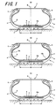
- FIGS. 1(a) to 1(c) are widthwise-sectional views showing the pneumatic tire according to one embodiment of the present invention.
- FIGS. 1(a) to 1(c) are widthwise-sectional views showing the rolling state of a pneumatic tire according to one embodiment of the present invention, wherein reference numeral 1 denotes the pneumatic tire as a whole, and reference numeral 2 denotes a rim on which the pneumatic tire 1 is assembled.
- Such a fixed state of the porous layer 9 can be achieved by a process illustrated by the sectional view of FIG 2(a) , by way of example.
- a raw material for the impregnation layer 23 is positioned and arranged on the inner surface of the unvulcanized inner liner rubber 22 of a green tire 21, over the entire circumference of the unvulcanized inner liner rubber 22, optionally with an adhesive or glue for temporary fixation.
- a raw material 24 for the porous layer is attached to the inner surface of the raw material for the impregnation layer 23, over the entire circumference, for example, in may cases with, but optionally without, an adhesive or glue for temporary fixation, to have a width that is substantially same as, or smaller than the width of the raw material for the impregnation layer 23.
- the green tire 21 is subjected to vulcanization so that the raw material 24 for the porous layer and the raw material for the impregnation layer 23 are urged toward the unvulcanized inner liner rubber 22 by a vulcanizing bladder that is inserted into inside of the green tire 21, and heated to the temperature of the green tire 21.
- the impregnation layer 10a itself can be fixedly attached to the inner liner 8
- the impregnation layer is joined to the inner liner 8 without an adhesive.
- the porous layer 9 is softened by the heat and brought into physical engagement with the impregnation layer 10a and/or fixedly attached to the impregnation layer 10a, so that the porous layer 9 is sufficiently firmly fixed to the inner liner 8.
- the porous layer 9 is fixedly attached to the inner liner 8 over the entire circumference, with a width centered at the tire equatorial plane E and corresponding to 30-100% of the ground-contact tread width. It is further preferred that the porous layer 9 which has been firmly attached in place includes a non-impregnated portion, i.e., the portion which is free from penetration of the impregnation layer 10a, having a thickness within a range of 0.5-50 mm.
- the impregnation layer itself may be comprised of various rubbers or suitable thermoplastic resins described above, having such properties that the raw material 23 for the impregnated layer is sufficiently softened under the vulcanizing temperature (120°C to 190°C) of the green tire, and can be sufficiently penetrated into the raw material 24 for the porous layer.
- the impregnation layer in the widthwise section may be arranged over the entirety of the inner surface of the inner liner 8.
- the impregnation layer includes, in addition to a portion 10a that is penetrated into the inner liner 8 over its entire thickness, a thin-layer portion 10b that is lined to the inner liner 8.
- the thin-layer portion 10b can be used as a releasing agent, thereby eliminating releasing step with respect to the vulcanizing bladder and the inner liner of the green tire upon vulcanization of the green tire, as described above.
- the inner liner rubber 22 is preferably afforded with an additional thickness exceeding the value with which the inner liner rubber 22 is impregnated into the porous layer.
- Pneumatic tires with a size of 215/45R17 were produced through vulcanization.
- the raw material 24 for the porous layer in the form of a non-woven cloth comprising polyethylene terephthalate fibers was arranged on the raw material 23 for the impregnation layer over the entire circumference, to have a width of 100 mm, which is approximately 60% of the ground-contact tread width.
- the example tire 1 was assembled to a rim of the size 17x7JJ, and inflated with air pressure of 210 kPa, before it was subjected to an actual running test on asphalt road, under a load of 3.92 kN and at the speed of 60 km/h.
- the cabin noise at the front driver's seat was measured to obtain the results as shown in the graph of FIG. 3 with a solid line.
- a peak value can be observed at the frequency around 235 kHz, which represents the cavity resonance noise.
Claims (13)
- Luftreifen, der eine poröse Schicht (9) aufweist, die fest an einer Reifeninnenfläche mittels einer Imprägnierungsschicht (10a) angebracht ist, wobei die Imprägnierungsschicht in die poröse Schicht über einen Teil einer Dicke der porösen Schicht imprägniert ist.
- Luftreifen nach Anspruch 1, bei dem die poröse Schicht fest an der Reifeninnenfläche über eine Breite über eine Reifenäquatorebene angebracht ist, wobei die Breite 30 % bis 100 % einer Reifenaufstandsbreite der Lauffläche entspricht.
- Luftreifen nach Anspruch 1 oder 2, bei dem die Imprägnierungsschicht zwischen der porösen Schicht und der Reifeninnenfläche über eine gesamte Breite der porösen Schicht angeordnet ist.
- Luftreifen nach einem der Ansprüche 1 bis 3, bei dem die Imprägnierungsschicht mit der Reifeninnenfläche wahlweise mit einer dazwischen angeordneten adhäsiven Schicht verbunden ist.
- Luftreifen nach einem der Ansprüche 1 bis 4, bei dem die Imprägnierungsschicht mindestens teilweise in der porösen Schicht imprägniert ist.
- Luftreifen nach einem der Ansprüche 1 bis 5, bei dem die Imprägnierungsschicht einen Gummi oder ein thermoplastisches Harz aufweist.
- Luftreifen nach einem der Ansprüche 1 bis 6, bei dem die Imprägnierungsschicht den gleichen Gummi aufweist, der den Innerliner des Reifens bildet.
- Luftreifen nach einem der Ansprüche 1 bis 7, bei dem die poröse Schicht einen nichtimprägnierten Abschnitt mit einer Dicke innerhalb eines Bereiches von 0,5 mm bis 50 mm aufweist.
- Luftreifen nach einem der Ansprüche 1 bis 8, bei dem die poröse Schicht einen Schaumkörper aufweist, und bei dem die Imprägnierungsschicht im Schaumkörper mit einer Imprägniertiefe imprägniert ist, die innerhalb eines Bereiches von 20 µm bis 5 mm liegt.
- Luftreifen nach einem der Ansprüche 1 bis 8, bei dem die poröse Schicht einen Vliesstoff aufweist, und bei dem die Imprägnierungsschicht im Vliesstoff mit einer Imprägniertiefe imprägniert ist, die einen mittleren Durchmesser der Fasern des Vliesstoffes übersteigt.
- Luftreifen nach Anspruch 10, bei dem der Vliesstoff einen nichtimprägnierten Abschnitt mit einer Dichte aufweist, die innerhalb eines Bereiches von 0,005 bis 0,2 liegt.
- Luftreifen nach Anspruch 10 oder 11, bei dem die Fasern, die den Vliesstoff bilden, einen mittleren Durchmesser aufweisen, der innerhalb eines Bereiches von 0,1 µm bis 200 µm liegt.
- Verfahren zur Herstellung eines Luftreifens, bei dem ein Rohstoff (23) für eine Imprägnierungsschicht in einen Rohstoff (24) für eine poröse Schicht imprägniert wird, und bei dem die resultierende poröse Schicht an einer Reifeninnenfläche unter Wärme und Druck fest angebracht wird, denen ein Reifenrohling während eines Vulkanisiervorganges unterworfen wird.
Applications Claiming Priority (2)
| Application Number | Priority Date | Filing Date | Title |
|---|---|---|---|
| JP2006329816 | 2006-12-06 | ||
| PCT/JP2007/072112 WO2008069010A1 (ja) | 2006-12-06 | 2007-11-14 | 空気入りタイヤおよびそれの製造方法 |
Publications (3)
| Publication Number | Publication Date |
|---|---|
| EP2093080A1 EP2093080A1 (de) | 2009-08-26 |
| EP2093080A4 EP2093080A4 (de) | 2010-09-01 |
| EP2093080B1 true EP2093080B1 (de) | 2011-12-21 |
Family
ID=39491915
Family Applications (1)
| Application Number | Title | Priority Date | Filing Date |
|---|---|---|---|
| EP07831842A Active EP2093080B1 (de) | 2006-12-06 | 2007-11-14 | Druckluftreifen und verfahren zur herstellung desselben |
Country Status (6)
| Country | Link |
|---|---|
| US (1) | US20090308519A1 (de) |
| EP (1) | EP2093080B1 (de) |
| JP (1) | JP5072861B2 (de) |
| CN (1) | CN101588930B (de) |
| AT (1) | ATE537979T1 (de) |
| WO (1) | WO2008069010A1 (de) |
Families Citing this family (20)
| Publication number | Priority date | Publication date | Assignee | Title |
|---|---|---|---|---|
| DE602004021448D1 (de) * | 2004-03-16 | 2009-07-16 | Sumitomo Rubber Ind | Pneumatischer Reifen mit einer Mehrzahl an Geräuschdämpfern |
| WO2009063723A1 (ja) * | 2007-11-13 | 2009-05-22 | Bridgestone Corporation | タイヤ |
| JP5707031B2 (ja) * | 2009-04-14 | 2015-04-22 | 株式会社ブリヂストン | 空気入りタイヤおよびその製造方法 |
| US20120060992A1 (en) * | 2009-04-24 | 2012-03-15 | Bridgestone Corporation | Pneumatic tire and method of manufacturing the same |
| JP2011020479A (ja) * | 2009-07-13 | 2011-02-03 | Sumitomo Rubber Ind Ltd | 制音体付空気入りタイヤ |
| US10081221B2 (en) * | 2010-11-24 | 2018-09-25 | The Goodyear Tire & Rubber Company | Balance pads for balancing pneumatic tires |
| ITTO20110472A1 (it) * | 2011-05-30 | 2012-12-01 | Bridgestone Corp | Pneumatico a bassa rumorosita' |
| CN105873774B (zh) * | 2013-11-21 | 2018-11-09 | 横滨橡胶株式会社 | 充气轮胎 |
| WO2016104663A1 (en) * | 2014-12-26 | 2016-06-30 | Compagnie Generale Des Etablissements Michelin | Tire for attenuating rolling noise |
| US10864782B2 (en) | 2016-09-07 | 2020-12-15 | Bridgestone Americas Tire Operations, Llc | Devices for reducing tire noise |
| WO2018057512A1 (en) | 2016-09-23 | 2018-03-29 | Bridgestone Americas Tire Operations, Llc | Devices for reducing tire noise |
| JP6845095B2 (ja) * | 2017-06-14 | 2021-03-17 | 株式会社ブリヂストン | 吸音部材付き空気入りタイヤ、及びタイヤ・リム組立体 |
| JP2019177753A (ja) * | 2018-03-30 | 2019-10-17 | 株式会社サンエー化研 | 空気入りタイヤ用吸音材及び空気入りタイヤ |
| JP7173474B2 (ja) | 2018-05-15 | 2022-11-16 | ブリヂストン アメリカズ タイヤ オペレーションズ、 エルエルシー | 多層インサートを有するタイヤ |
| TWI741200B (zh) * | 2018-07-20 | 2021-10-01 | 正新橡膠工業股份有限公司 | 輪胎噪音降低裝置 |
| US20210300126A1 (en) * | 2018-07-24 | 2021-09-30 | The Yokohama Rubber Co., Ltd. | Pneumatic Tire |
| US20210291470A1 (en) * | 2018-07-24 | 2021-09-23 | The Yokohama Rubber Co., Ltd. | Pneumatic Tire and Method of Manufacturing the Same |
| WO2020022159A1 (ja) * | 2018-07-24 | 2020-01-30 | 横浜ゴム株式会社 | 空気入りタイヤ |
| JP2020093680A (ja) * | 2018-12-13 | 2020-06-18 | 株式会社ブリヂストン | 乗用車用空気入りラジアルタイヤ |
| JP7140669B2 (ja) * | 2018-12-17 | 2022-09-21 | 株式会社ブリヂストン | 空気入りタイヤ |
Family Cites Families (14)
| Publication number | Priority date | Publication date | Assignee | Title |
|---|---|---|---|---|
| JPH02127101A (ja) * | 1988-11-04 | 1990-05-15 | Sumitomo Rubber Ind Ltd | 空気入りタイヤ |
| JPH0640207A (ja) * | 1992-07-24 | 1994-02-15 | Yokohama Rubber Co Ltd:The | 空気入りタイヤ及びその製造方法 |
| JP3622957B2 (ja) | 2001-08-02 | 2005-02-23 | 住友ゴム工業株式会社 | 空気入りタイヤとリムとの組立体 |
| EP1253025B1 (de) * | 2001-04-16 | 2006-02-08 | Sumitomo Rubber Industries Ltd. | Reifengeräusch reduzierende Vorrichtung |
| JP3974437B2 (ja) * | 2002-03-28 | 2007-09-12 | 住友ゴム工業株式会社 | 空気入りタイヤ |
| JP2004082387A (ja) * | 2002-08-23 | 2004-03-18 | Bridgestone Corp | 空気入りタイヤの製造方法、空気入りタイヤ、及びタイヤ・リム組立体 |
| RU2293091C2 (ru) * | 2002-12-23 | 2007-02-10 | Инвиста Технолоджис С,А,Р,Л, | Способ достижения прямой адгезии между текстильными армирующими материалами и каучуком |
| US7556075B2 (en) * | 2003-08-04 | 2009-07-07 | The Yokohama Rubber Co., Ltd. | Low noise pneumatic tire |
| KR101148012B1 (ko) * | 2003-08-04 | 2012-05-25 | 미쯔비시 지도샤 고교 가부시끼가이샤 | 저소음 공기 타이어 |
| JP4428107B2 (ja) * | 2004-03-24 | 2010-03-10 | 横浜ゴム株式会社 | 空気入りタイヤ及びその製造方法 |
| JP4264053B2 (ja) * | 2004-12-01 | 2009-05-13 | 住友ゴム工業株式会社 | 空気入りタイヤの製造方法 |
| US7389802B2 (en) * | 2004-12-30 | 2008-06-24 | The Goodyear Tire & Rubber Co. | Tire with double layer innerliner |
| JP4843435B2 (ja) * | 2006-09-22 | 2011-12-21 | 住友ゴム工業株式会社 | 空気入りタイヤの製造方法 |
| JP4891727B2 (ja) * | 2006-10-11 | 2012-03-07 | 住友ゴム工業株式会社 | 空気入りタイヤの製造方法 |
-
2007
- 2007-11-14 US US12/517,306 patent/US20090308519A1/en not_active Abandoned
- 2007-11-14 JP JP2008548212A patent/JP5072861B2/ja active Active
- 2007-11-14 CN CN200780045212XA patent/CN101588930B/zh not_active Expired - Fee Related
- 2007-11-14 EP EP07831842A patent/EP2093080B1/de active Active
- 2007-11-14 WO PCT/JP2007/072112 patent/WO2008069010A1/ja active Application Filing
- 2007-11-14 AT AT07831842T patent/ATE537979T1/de active
Also Published As
| Publication number | Publication date |
|---|---|
| JP5072861B2 (ja) | 2012-11-14 |
| US20090308519A1 (en) | 2009-12-17 |
| ATE537979T1 (de) | 2012-01-15 |
| CN101588930B (zh) | 2011-08-17 |
| EP2093080A1 (de) | 2009-08-26 |
| EP2093080A4 (de) | 2010-09-01 |
| CN101588930A (zh) | 2009-11-25 |
| WO2008069010A1 (ja) | 2008-06-12 |
| JPWO2008069010A1 (ja) | 2010-03-18 |
Similar Documents
| Publication | Publication Date | Title |
|---|---|---|
| EP2093080B1 (de) | Druckluftreifen und verfahren zur herstellung desselben | |
| US7556075B2 (en) | Low noise pneumatic tire | |
| EP1876038B1 (de) | Aus einem luftreifen und einer felge bestehende anordnung | |
| EP2017092B1 (de) | Luftreifensatz | |
| US7387141B2 (en) | Low noise pneumatic tire | |
| EP2067633B1 (de) | Reifenlärmverringerungsvorrichtung und luftreifen | |
| EP1559590B1 (de) | Reifenlärmminderungssystem | |
| CN108513551B (zh) | 充气轮胎 | |
| EP1666274B1 (de) | Luftreifen und Verfahren zu seiner Herstellung | |
| EP0507184A1 (de) | Sicherheitsluftreifen | |
| EP3581399B1 (de) | Luftreifen | |
| EP1002668B1 (de) | Luftreifen | |
| EP0686514B1 (de) | Radialer Luftreifen und Verfahren zur Herstellung | |
| CN111094013A (zh) | 充气轮胎及其制造方法 | |
| JP2009045747A (ja) | 空気入りタイヤの製造方法及び空気入りタイヤ | |
| EP3088207B1 (de) | Seitenverstärkter notlaufreifen | |
| EP3895912B1 (de) | Luftreifen | |
| JP2009039901A (ja) | 空気入りタイヤの製造方法及び空気入りタイヤ | |
| EP0893236A1 (de) | Selbstdichtender Luftreifen und Verfahren zu seiner Herstellung | |
| WO2019092631A1 (en) | Method for the construction of a pneumatic tyre | |
| JP4257723B2 (ja) | タイヤとリムの組立体 | |
| US20230166566A1 (en) | Pneumatic tyre | |
| JP2002172918A (ja) | 安全空気入りタイヤ | |
| EP2865547B1 (de) | Luftreifen | |
| JP2005001547A (ja) | タイヤ |
Legal Events
| Date | Code | Title | Description |
|---|---|---|---|
| PUAI | Public reference made under article 153(3) epc to a published international application that has entered the european phase |
Free format text: ORIGINAL CODE: 0009012 |
|
| 17P | Request for examination filed |
Effective date: 20090605 |
|
| AK | Designated contracting states |
Kind code of ref document: A1 Designated state(s): AT BE BG CH CY CZ DE DK EE ES FI FR GB GR HU IE IS IT LI LT LU LV MC MT NL PL PT RO SE SI SK TR |
|
| DAX | Request for extension of the european patent (deleted) | ||
| A4 | Supplementary search report drawn up and despatched |
Effective date: 20100803 |
|
| RIC1 | Information provided on ipc code assigned before grant |
Ipc: B60C 5/00 20060101ALI20100728BHEP Ipc: B29D 30/08 20060101ALI20100728BHEP Ipc: B60C 19/00 20060101AFI20100728BHEP |
|
| REG | Reference to a national code |
Ref country code: DE Ref legal event code: R079 Ref document number: 602007019576 Country of ref document: DE Free format text: PREVIOUS MAIN CLASS: B60C0005000000 Ipc: B60C0019000000 |
|
| RIC1 | Information provided on ipc code assigned before grant |
Ipc: B60C 5/00 20060101ALI20110408BHEP Ipc: B60C 19/00 20060101AFI20110408BHEP Ipc: B29D 30/08 20060101ALI20110408BHEP |
|
| GRAP | Despatch of communication of intention to grant a patent |
Free format text: ORIGINAL CODE: EPIDOSNIGR1 |
|
| RIN1 | Information on inventor provided before grant (corrected) |
Inventor name: ISHIHARA, TAIGAC/O BRIDGESTONE CORPORATION |
|
| GRAS | Grant fee paid |
Free format text: ORIGINAL CODE: EPIDOSNIGR3 |
|
| GRAA | (expected) grant |
Free format text: ORIGINAL CODE: 0009210 |
|
| AK | Designated contracting states |
Kind code of ref document: B1 Designated state(s): AT BE BG CH CY CZ DE DK EE ES FI FR GB GR HU IE IS IT LI LT LU LV MC MT NL PL PT RO SE SI SK TR |
|
| REG | Reference to a national code |
Ref country code: GB Ref legal event code: FG4D |
|
| REG | Reference to a national code |
Ref country code: CH Ref legal event code: EP |
|
| REG | Reference to a national code |
Ref country code: AT Ref legal event code: REF Ref document number: 537979 Country of ref document: AT Kind code of ref document: T Effective date: 20120115 |
|
| REG | Reference to a national code |
Ref country code: IE Ref legal event code: FG4D |
|
| REG | Reference to a national code |
Ref country code: DE Ref legal event code: R096 Ref document number: 602007019576 Country of ref document: DE Effective date: 20120308 |
|
| REG | Reference to a national code |
Ref country code: NL Ref legal event code: VDEP Effective date: 20111221 |
|
| PG25 | Lapsed in a contracting state [announced via postgrant information from national office to epo] |
Ref country code: LT Free format text: LAPSE BECAUSE OF FAILURE TO SUBMIT A TRANSLATION OF THE DESCRIPTION OR TO PAY THE FEE WITHIN THE PRESCRIBED TIME-LIMIT Effective date: 20111221 |
|
| LTIE | Lt: invalidation of european patent or patent extension |
Effective date: 20111221 |
|
| PG25 | Lapsed in a contracting state [announced via postgrant information from national office to epo] |
Ref country code: NL Free format text: LAPSE BECAUSE OF FAILURE TO SUBMIT A TRANSLATION OF THE DESCRIPTION OR TO PAY THE FEE WITHIN THE PRESCRIBED TIME-LIMIT Effective date: 20111221 Ref country code: LV Free format text: LAPSE BECAUSE OF FAILURE TO SUBMIT A TRANSLATION OF THE DESCRIPTION OR TO PAY THE FEE WITHIN THE PRESCRIBED TIME-LIMIT Effective date: 20111221 Ref country code: SE Free format text: LAPSE BECAUSE OF FAILURE TO SUBMIT A TRANSLATION OF THE DESCRIPTION OR TO PAY THE FEE WITHIN THE PRESCRIBED TIME-LIMIT Effective date: 20111221 Ref country code: SI Free format text: LAPSE BECAUSE OF FAILURE TO SUBMIT A TRANSLATION OF THE DESCRIPTION OR TO PAY THE FEE WITHIN THE PRESCRIBED TIME-LIMIT Effective date: 20111221 Ref country code: GR Free format text: LAPSE BECAUSE OF FAILURE TO SUBMIT A TRANSLATION OF THE DESCRIPTION OR TO PAY THE FEE WITHIN THE PRESCRIBED TIME-LIMIT Effective date: 20120322 |
|
| PG25 | Lapsed in a contracting state [announced via postgrant information from national office to epo] |
Ref country code: BE Free format text: LAPSE BECAUSE OF FAILURE TO SUBMIT A TRANSLATION OF THE DESCRIPTION OR TO PAY THE FEE WITHIN THE PRESCRIBED TIME-LIMIT Effective date: 20111221 Ref country code: CY Free format text: LAPSE BECAUSE OF FAILURE TO SUBMIT A TRANSLATION OF THE DESCRIPTION OR TO PAY THE FEE WITHIN THE PRESCRIBED TIME-LIMIT Effective date: 20111221 |
|
| PG25 | Lapsed in a contracting state [announced via postgrant information from national office to epo] |
Ref country code: SK Free format text: LAPSE BECAUSE OF FAILURE TO SUBMIT A TRANSLATION OF THE DESCRIPTION OR TO PAY THE FEE WITHIN THE PRESCRIBED TIME-LIMIT Effective date: 20111221 Ref country code: CZ Free format text: LAPSE BECAUSE OF FAILURE TO SUBMIT A TRANSLATION OF THE DESCRIPTION OR TO PAY THE FEE WITHIN THE PRESCRIBED TIME-LIMIT Effective date: 20111221 Ref country code: IS Free format text: LAPSE BECAUSE OF FAILURE TO SUBMIT A TRANSLATION OF THE DESCRIPTION OR TO PAY THE FEE WITHIN THE PRESCRIBED TIME-LIMIT Effective date: 20120421 Ref country code: BG Free format text: LAPSE BECAUSE OF FAILURE TO SUBMIT A TRANSLATION OF THE DESCRIPTION OR TO PAY THE FEE WITHIN THE PRESCRIBED TIME-LIMIT Effective date: 20120321 Ref country code: EE Free format text: LAPSE BECAUSE OF FAILURE TO SUBMIT A TRANSLATION OF THE DESCRIPTION OR TO PAY THE FEE WITHIN THE PRESCRIBED TIME-LIMIT Effective date: 20111221 |
|
| PG25 | Lapsed in a contracting state [announced via postgrant information from national office to epo] |
Ref country code: PL Free format text: LAPSE BECAUSE OF FAILURE TO SUBMIT A TRANSLATION OF THE DESCRIPTION OR TO PAY THE FEE WITHIN THE PRESCRIBED TIME-LIMIT Effective date: 20111221 Ref country code: RO Free format text: LAPSE BECAUSE OF FAILURE TO SUBMIT A TRANSLATION OF THE DESCRIPTION OR TO PAY THE FEE WITHIN THE PRESCRIBED TIME-LIMIT Effective date: 20111221 Ref country code: PT Free format text: LAPSE BECAUSE OF FAILURE TO SUBMIT A TRANSLATION OF THE DESCRIPTION OR TO PAY THE FEE WITHIN THE PRESCRIBED TIME-LIMIT Effective date: 20120423 |
|
| REG | Reference to a national code |
Ref country code: AT Ref legal event code: MK05 Ref document number: 537979 Country of ref document: AT Kind code of ref document: T Effective date: 20111221 |
|
| PLBE | No opposition filed within time limit |
Free format text: ORIGINAL CODE: 0009261 |
|
| STAA | Information on the status of an ep patent application or granted ep patent |
Free format text: STATUS: NO OPPOSITION FILED WITHIN TIME LIMIT |
|
| PG25 | Lapsed in a contracting state [announced via postgrant information from national office to epo] |
Ref country code: DK Free format text: LAPSE BECAUSE OF FAILURE TO SUBMIT A TRANSLATION OF THE DESCRIPTION OR TO PAY THE FEE WITHIN THE PRESCRIBED TIME-LIMIT Effective date: 20111221 |
|
| 26N | No opposition filed |
Effective date: 20120924 |
|
| REG | Reference to a national code |
Ref country code: DE Ref legal event code: R097 Ref document number: 602007019576 Country of ref document: DE Effective date: 20120924 |
|
| PG25 | Lapsed in a contracting state [announced via postgrant information from national office to epo] |
Ref country code: AT Free format text: LAPSE BECAUSE OF FAILURE TO SUBMIT A TRANSLATION OF THE DESCRIPTION OR TO PAY THE FEE WITHIN THE PRESCRIBED TIME-LIMIT Effective date: 20111221 |
|
| PG25 | Lapsed in a contracting state [announced via postgrant information from national office to epo] |
Ref country code: ES Free format text: LAPSE BECAUSE OF FAILURE TO SUBMIT A TRANSLATION OF THE DESCRIPTION OR TO PAY THE FEE WITHIN THE PRESCRIBED TIME-LIMIT Effective date: 20120401 |
|
| PG25 | Lapsed in a contracting state [announced via postgrant information from national office to epo] |
Ref country code: FI Free format text: LAPSE BECAUSE OF FAILURE TO SUBMIT A TRANSLATION OF THE DESCRIPTION OR TO PAY THE FEE WITHIN THE PRESCRIBED TIME-LIMIT Effective date: 20111221 |
|
| REG | Reference to a national code |
Ref country code: CH Ref legal event code: PL |
|
| PG25 | Lapsed in a contracting state [announced via postgrant information from national office to epo] |
Ref country code: LI Free format text: LAPSE BECAUSE OF NON-PAYMENT OF DUE FEES Effective date: 20121130 Ref country code: CH Free format text: LAPSE BECAUSE OF NON-PAYMENT OF DUE FEES Effective date: 20121130 |
|
| REG | Reference to a national code |
Ref country code: IE Ref legal event code: MM4A |
|
| PG25 | Lapsed in a contracting state [announced via postgrant information from national office to epo] |
Ref country code: IE Free format text: LAPSE BECAUSE OF NON-PAYMENT OF DUE FEES Effective date: 20121114 |
|
| PG25 | Lapsed in a contracting state [announced via postgrant information from national office to epo] |
Ref country code: MT Free format text: LAPSE BECAUSE OF FAILURE TO SUBMIT A TRANSLATION OF THE DESCRIPTION OR TO PAY THE FEE WITHIN THE PRESCRIBED TIME-LIMIT Effective date: 20111221 |
|
| PG25 | Lapsed in a contracting state [announced via postgrant information from national office to epo] |
Ref country code: TR Free format text: LAPSE BECAUSE OF FAILURE TO SUBMIT A TRANSLATION OF THE DESCRIPTION OR TO PAY THE FEE WITHIN THE PRESCRIBED TIME-LIMIT Effective date: 20111221 Ref country code: MC Free format text: LAPSE BECAUSE OF NON-PAYMENT OF DUE FEES Effective date: 20121130 |
|
| PG25 | Lapsed in a contracting state [announced via postgrant information from national office to epo] |
Ref country code: LU Free format text: LAPSE BECAUSE OF NON-PAYMENT OF DUE FEES Effective date: 20121114 |
|
| PG25 | Lapsed in a contracting state [announced via postgrant information from national office to epo] |
Ref country code: HU Free format text: LAPSE BECAUSE OF FAILURE TO SUBMIT A TRANSLATION OF THE DESCRIPTION OR TO PAY THE FEE WITHIN THE PRESCRIBED TIME-LIMIT Effective date: 20071114 |
|
| REG | Reference to a national code |
Ref country code: FR Ref legal event code: CA Effective date: 20140812 |
|
| REG | Reference to a national code |
Ref country code: FR Ref legal event code: PLFP Year of fee payment: 9 |
|
| REG | Reference to a national code |
Ref country code: FR Ref legal event code: PLFP Year of fee payment: 10 |
|
| REG | Reference to a national code |
Ref country code: FR Ref legal event code: PLFP Year of fee payment: 11 |
|
| PGFP | Annual fee paid to national office [announced via postgrant information from national office to epo] |
Ref country code: DE Payment date: 20191121 Year of fee payment: 13 |
|
| PGFP | Annual fee paid to national office [announced via postgrant information from national office to epo] |
Ref country code: IT Payment date: 20191128 Year of fee payment: 13 |
|
| PGFP | Annual fee paid to national office [announced via postgrant information from national office to epo] |
Ref country code: GB Payment date: 20191120 Year of fee payment: 13 |
|
| REG | Reference to a national code |
Ref country code: DE Ref legal event code: R119 Ref document number: 602007019576 Country of ref document: DE |
|
| GBPC | Gb: european patent ceased through non-payment of renewal fee |
Effective date: 20201114 |
|
| PG25 | Lapsed in a contracting state [announced via postgrant information from national office to epo] |
Ref country code: IT Free format text: LAPSE BECAUSE OF NON-PAYMENT OF DUE FEES Effective date: 20201114 |
|
| PG25 | Lapsed in a contracting state [announced via postgrant information from national office to epo] |
Ref country code: GB Free format text: LAPSE BECAUSE OF NON-PAYMENT OF DUE FEES Effective date: 20201114 Ref country code: DE Free format text: LAPSE BECAUSE OF NON-PAYMENT OF DUE FEES Effective date: 20210601 |
|
| P01 | Opt-out of the competence of the unified patent court (upc) registered |
Effective date: 20230531 |
|
| PGFP | Annual fee paid to national office [announced via postgrant information from national office to epo] |
Ref country code: FR Payment date: 20231120 Year of fee payment: 17 |