EP2092843A1 - Applicator with collar-like attachment projections, in particular for mascara or similar cosmetics - Google Patents
Applicator with collar-like attachment projections, in particular for mascara or similar cosmetics Download PDFInfo
- Publication number
- EP2092843A1 EP2092843A1 EP09006969A EP09006969A EP2092843A1 EP 2092843 A1 EP2092843 A1 EP 2092843A1 EP 09006969 A EP09006969 A EP 09006969A EP 09006969 A EP09006969 A EP 09006969A EP 2092843 A1 EP2092843 A1 EP 2092843A1
- Authority
- EP
- European Patent Office
- Prior art keywords
- bristle
- base body
- applicator according
- applicator
- stem
- Prior art date
- Legal status (The legal status is an assumption and is not a legal conclusion. Google has not performed a legal analysis and makes no representation as to the accuracy of the status listed.)
- Granted
Links
Images

Classifications
-
- A—HUMAN NECESSITIES
- A46—BRUSHWARE
- A46B—BRUSHES
- A46B9/00—Arrangements of the bristles in the brush body
- A46B9/02—Position or arrangement of bristles in relation to surface of the brush body, e.g. inclined, in rows, in groups
- A46B9/021—Position or arrangement of bristles in relation to surface of the brush body, e.g. inclined, in rows, in groups arranged like in cosmetics brushes, e.g. mascara, nail polish, eye shadow
-
- A—HUMAN NECESSITIES
- A45—HAND OR TRAVELLING ARTICLES
- A45D—HAIRDRESSING OR SHAVING EQUIPMENT; EQUIPMENT FOR COSMETICS OR COSMETIC TREATMENTS, e.g. FOR MANICURING OR PEDICURING
- A45D40/00—Casings or accessories specially adapted for storing or handling solid or pasty toiletry or cosmetic substances, e.g. shaving soaps or lipsticks
- A45D40/26—Appliances specially adapted for applying pasty paint, e.g. using roller, using a ball
- A45D40/262—Appliances specially adapted for applying pasty paint, e.g. using roller, using a ball using a brush or the like
-
- A—HUMAN NECESSITIES
- A46—BRUSHWARE
- A46B—BRUSHES
- A46B9/00—Arrangements of the bristles in the brush body
- A46B9/02—Position or arrangement of bristles in relation to surface of the brush body, e.g. inclined, in rows, in groups
- A46B9/028—Bristle profile, the end of the bristle defining a surface other than a single plane or deviating from a simple geometric form, e.g. cylinder, sphere or cone
-
- A—HUMAN NECESSITIES
- A46—BRUSHWARE
- A46D—MANUFACTURE OF BRUSHES
- A46D1/00—Bristles; Selection of materials for bristles
-
- A—HUMAN NECESSITIES
- A46—BRUSHWARE
- A46D—MANUFACTURE OF BRUSHES
- A46D1/00—Bristles; Selection of materials for bristles
- A46D1/02—Bristles details
- A46D1/0253—Bristles having a shape which is not a straight line, e.g. curved, "S", hook, loop
-
- A—HUMAN NECESSITIES
- A46—BRUSHWARE
- A46B—BRUSHES
- A46B2200/00—Brushes characterized by their functions, uses or applications
- A46B2200/10—For human or animal care
- A46B2200/1046—Brush used for applying cosmetics
- A46B2200/1053—Cosmetics applicator specifically for mascara
-
- A—HUMAN NECESSITIES
- A46—BRUSHWARE
- A46B—BRUSHES
- A46B2200/00—Brushes characterized by their functions, uses or applications
- A46B2200/10—For human or animal care
- A46B2200/1046—Brush used for applying cosmetics
- A46B2200/1053—Cosmetics applicator specifically for mascara
- A46B2200/106—Cosmetics applicator specifically for mascara including comb like element
Definitions
- the invention is directed to an applicator, in particular for mascara, hair dye or similar cosmetics, comprising an elongated, connectable with a stem base body of a comparatively hard plastic and a tubular bristle body with bristle-like, radially projecting lugs of a relatively soft plastic.
- an applicator is known from EP 0 038 524 A1 respectively. DE 25 59 273 A1 ,
- the invention has the object of developing such an applicator so that it has stable operating characteristics with advantageous manufacturability.
- the bristle body is axially fixed relative to the base body.
- the base body has an annular bead which engages in a corresponding annular groove of the bristle body, whereby the axial fixation is accomplished.
- the annular groove is formed on the base body.
- This fixing cap may conveniently have a stem approach, which engages in a recess of the body, wherein the stem approach in particular has an annular bead which can be latched into an annular groove in the recess of the body.
- the free, distal end of the base body is provided with an integrally molded, radially projecting fixing cap whose outer diameter corresponds to a thermal deformation with a punch about the outer diameter of the bristle body, and which the bristle body, the two-component injection molding molded or pushed over, axially fixed.
- the bristle body in the region of the free distal end of an end wall has, which rests against the end wall of the base body.
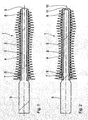
- An applicator 1 shown in the drawing comprises a base body 2 of a relatively hard material and comparatively hard plastic and a bristle body 3 of a relatively soft plastic with a plurality of molded, radially outwardly extending bristle-like projections 4.
- the main body 2 is integrally molded with a handle extension 5, which is connectable to a stem.
- the stem may be connected in a conventional manner with the inside of the lid a screw cap, which in turn on the external thread of a reservoir for the respective cosmetic, z. B. mascara, is screwed.
- the main body 2 has an annular bead 6, which engages in a corresponding circumferential groove 7 on the bristle body 3.
- a fixing cap 9 is provided, whose outer diameter corresponds approximately to the outer diameter of the bristle body 3.
- FIG. 2 illustrated embodiment which is substantially issued as the embodiment according to FIG. 1 , instead of the fixing cap 9, an end wall 10 injected integrally with the bristle body 3 is provided, which abuts the end face 11 at the distal end 8 of the main body 2.
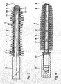
- a fixing cap 12 corresponding to the fixing cap 9 according to the embodiment in FIG. 1 is not formed integrally with the base body 2, but has a handle extension 13 which engages in a recess 14 in the base body 2 and is fixed there by means of a torus 15 and a corresponding annular groove 16 on the inner wall of the recess 14.
- the base body 2 has a plurality of collar-like projections 17, which have a frusto-conical shape such that the truncated cone tapers to the free end. Accordingly, when the bristle body 3 is mounted on the main body 2, the protrusions 17 act like barbs and prevent the bristle body 3 from coming off.
- the base body 2 is dimensioned so that a free outer end 18 projects beyond the bristle body 3.
- a heated punch 19 By pressing a heated punch 19 in the direction of arrow 20, this free end 18 is then deformed so that a fixing cap is formed, as in FIG. 1 is shown.
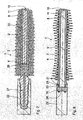
- the bristle body 3 has a forceps-like inner end 21.
- a stem attachment 22 is provided with a conical recess 23.
- the conical opening 23 engages over the likewise conical region 24 of the pliers approach 21, so that end-side gun arms 25 are pressed into a bore 26 of the base body 2 and thereby a stable connection is created.
- the base body 2 has a longitudinal groove 27 which opens into a radial bore 28. Adhesive can be pressed in via the groove 27, which exits via the radial bore 28 and reliably connects the bristle body 3 to the base body 2.
- FIG. 8 an embodiment is shown in which the base body 2 is integrally formed with a handle neck 22, the corresponding FIG. 6 a conical recess 23 which is formed as an annular gap, in which engages the also conical end 29 of the bristle body and is fixed by a radial pin 30.
- the inner end 31 of the bristle body 3 merges into the stem neck 22 in a conically aligned manner.
- the recess may be dimensioned in the mounting projection 22 relative to the stem extension of the base body 2 so that an annular gap is formed, in which a projection of the bristle body 3 is received.
- the bristle body 2 may further comprise two lugs, which extend at a distance from each other and end inwardly projecting pins. If then the stem approach 22 is postponed, the approaches pliers are pressed by the inner wall of the conical recess 23 of the stem approach 22 inward and then engage in corresponding recesses of the body 2 and are thereby fixed.
- the stem approach 2 can be polygonal, z. B. five-edged to achieve in this way an anti-rotation.
- the bristles are, as drawn in the embodiment, preferably conical, but may also be round and have only a conical or chisel-shaped tip.
- the cross section of the bristles may be round or even deviate from a round geometry.
- the number of bristles can be between 30 and 600.
- the bristles can form a comb in the axial direction.
Abstract
Description
Die Erfindung richtet sich auf einen Applikator, insbesondere für Mascara, Haarfärbemittel oder ähnliche Kosmetika, umfassend einen länglichen, mit einem Stiel verbindbaren Grundkörper aus einem vergleichsweise harten Kunststoff und einen rohrförmigen Borstenkörper mit borstenartigen, radial wegstehenden Ansätzen aus einem relativ weichen Kunststoff. Ein derartiger Applikator ist bekannt aus
Der grundsätzliche Vorteil eines derartigen Applikators besteht darin, dass er kostengünstig herstellbar ist. Der relativ harte Kunststoff des Grundkörpers gibt die erforderliche Stabilität, wohingegen der weiche Kunststoff des Borstenkörpers die Ausbildung entsprechend weicher borstenartiger Ansätze ermöglicht.The fundamental advantage of such an applicator is that it can be produced inexpensively. The relatively hard plastic of the base body gives the required stability, whereas the soft plastic of the bristle body allows the formation of correspondingly soft bristle-like approaches.
Der Erfindung liegt die Aufgabe zugrunde, einen solchen Applikator so weiterzubilden, dass er bei vorteilhafter Herstellbarkeit stabile Gebrauchseigenschaften aufweist.The invention has the object of developing such an applicator so that it has stable operating characteristics with advantageous manufacturability.
Zur Lösung dieser Aufgabe ist vorgesehen, dass der Borstenkörper gegenüber dem Grundkörper axial fixiert ist.To solve this problem, it is provided that the bristle body is axially fixed relative to the base body.
Durch eine solche axiale Fixierung wird erreicht, dass im Gebrauch, insbesondere auch beim Herausziehen und Hineinstecken des Applikators in einen Vorratsbehälter, z. B. bei einer Mascara-Einheit, beim Passieren einer Abstreifeinrichtung stabil bleibt.By such axial fixation is achieved that in use, especially when pulling out and inserting the applicator in a reservoir, z. B. in a mascara unit, when passing a stripping device remains stable.
In weiterer Ausgestaltung der Erfindung ist vorgesehen, dass der Grundkörper einen Ringwulst aufweist, der in eine korrespondierende Ringnut des Borstenkörpers eingreift, wodurch die axiale Fixierung bewerkstelligt wird. Im Rahmen der Erfindung kann in Umkehrung dieser Lösung auch vorgesehen sein, dass die Ringnut am Grundkörper ausgebildet ist.In a further embodiment of the invention it is provided that the base body has an annular bead which engages in a corresponding annular groove of the bristle body, whereby the axial fixation is accomplished. In the context of the invention can be provided in reversal of this solution, that the annular groove is formed on the base body.
Weiterhin kann mit Vorteil auf den Grundkörper am freien, distalen Ende eine den Borstenkörper übergreifende Fixierungskappe aufgesetzt werden.Furthermore, it can be placed with advantage on the body at the free, distal end of the bristle body cross-fixation cap.
Diese Fixierungskappe kann günstigerweise einen Stielansatz aufweisen, der in eine Ausnehmung des Grundkörpers eingreift, wobei der Stielansatz insbesondere einen Ringwulst aufweist, der in eine Ringnut in der Ausnehmung des Grundkörpers einrastbar ist.This fixing cap may conveniently have a stem approach, which engages in a recess of the body, wherein the stem approach in particular has an annular bead which can be latched into an annular groove in the recess of the body.
Bei einer anderen Ausführungsform ist das freie, distale Ende des Grundkörpers mit einer einstückig angespritzten, radial vorspringenden Fixierungskappe versehen, deren Außendurchmesser nach einer thermischen Verformung mit einem Stempel etwa dem Außendurchmesser des Borstenkörpers entspricht, und welche den Borstenkörper, der im 2-Komponenten-Spritzgießverfahren angespritzt oder übergeschoben sein kann, axial fixiert.In another embodiment, the free, distal end of the base body is provided with an integrally molded, radially projecting fixing cap whose outer diameter corresponds to a thermal deformation with a punch about the outer diameter of the bristle body, and which the bristle body, the two-component injection molding molded or pushed over, axially fixed.
Bei einer dritten Ausführungsform ist vorgesehen, dass der Borstenkörper im Bereich des freien distalen Endes eine Stirnwand aufweist, welche an der Stirnwand des Grundkörpers anliegt.In a third embodiment it is provided that the bristle body in the region of the free distal end of an end wall has, which rests against the end wall of the base body.
Nachfolgend wird die Erfindung anhand bevorzugter Ausführungsbeispiele in Verbindung mit der Zeichnung näher beschrieben. Dabei zeigen:
- Fig. 1:
- einen Längsschnitt durch eine erste Ausführungsform eines erfindungsgemäßen Applikators,
- Fig. 2:
- einen Längsschnitt durch eine zweite Ausführungsform,
- Fig. 3:
- einen Längsschnitt durch eine dritte Ausführungsform,
- Fig. 4:
- einen Längsschnitt durch eine vierte Ausführungsform,
- Fig. 5:
- einen Längsschnitt, der eine Möglichkeit der Realisierung der Ausführungsform nach
Figur 1 veranschaulicht, - Fig. 6:
- einen Längsschnitt einer Ausführungsform nach
Figur 2 - Fig. 7:
- einen Längsschnitt
entsprechend Figur 6 betreffend eine weitere Befestigungsvariante, und - Fig. 8:
- einen Längsschnitt entsprechend der Ausführungsform nach
Figur 2
- Fig. 1:
- a longitudinal section through a first embodiment of an applicator according to the invention,
- Fig. 2:
- a longitudinal section through a second embodiment,
- 3:
- a longitudinal section through a third embodiment,
- 4:
- a longitudinal section through a fourth embodiment,
- Fig. 5:
- a longitudinal section, the possibility of realization of the embodiment according to
FIG. 1 illustrates - Fig. 6:
- a longitudinal section of an embodiment according to
FIG. 2 concerning the fixation of the brush on the style, - Fig. 7:
- a longitudinal section accordingly
FIG. 6 concerning a further fastening variant, and - Fig. 8:
- a longitudinal section according to the embodiment according to
FIG. 2 to illustrate a third fastening variant.
Ein in der Zeichnung dargestellter Applikator 1 umfasst einen Grundkörper 2 aus einem relativ harten Material und vergleichsweise harten Kunststoff und einen Borstenkörper 3 aus einem relativ weichen Kunststoff mit einer Mehrzahl angespritzter, sich radial nach außen erstreckender borstenartiger Ansätze 4. Der Grundkörper 2 ist mit einem Stielansatz 5 einstückig gespritzt, der mit einem Stiel verbindbar ist.An applicator 1 shown in the drawing comprises a
Der Stiel kann in an sich bekannter Weise mit der Innenseite des Deckels eine Schraubkappe verbunden sein, welche ihrerseits auf das Außengewinde eines Vorratsbehälters für das jeweilige Kosmetikum, z. B. Mascara, aufgeschraubt ist.The stem may be connected in a conventional manner with the inside of the lid a screw cap, which in turn on the external thread of a reservoir for the respective cosmetic, z. B. mascara, is screwed.
Zur axialen Fixierung des Borstenkörpers 3 relativ zum Grundkörper 2, insbesondere beim Passieren einer Abstreifeinrichtung, weist der Grundkörper 2 einen Ringwulst 6 auf, der in eine korrespondierende umlaufende Nut 7 an dem Borstenkörper 3 eingreift. Eine weitere Fixierung ist dadurch gegeben, dass am distalen Ende 8 des Grundkörpers 2 eine Fixierungskappe 9 vorgesehen ist, deren Außendurchmesser etwa dem Außendurchmesser des Borstenkörpers 3 entspricht.For axially fixing the
Bei der in
Bei der Ausführungsform nach
Bei der Ausführungsform nach
Gemäß
Bei der Ausführungsform nach
Bei der Ausführungsform nach
In
Durch diese Ausgestaltung wird erreicht, dass beim Abstreifvorgang ein Verhaken des Abstreifers am Übergangsbereich vermieden wird. Es wird erreicht, dass der biegeschlaffe Borstenkörper 3 nicht von dem steifen Grundkörper 2 abgezogen wird.By this configuration it is achieved that during stripping a snagging of the scraper is avoided at the transition region. It is achieved that the pliable bristle
Wie insbesondere aus
Der Borstenkörper 2 kann weiterhin zwei Ansätze besitzen, die im Abstand voneinander verlaufen und endseitig nach innen vorspringende Zapfen aufweisen. Wird dann der Stielansatz 22 aufgeschoben, werden die Ansätze zangenartig durch die Innenwand der konischen Ausnehmung 23 des Stielansatzes 22 nach innen gedrückt und greifen dann in korrespondierende Ausnehmungen des Grundkörpers 2 ein und werden hierdurch fixiert.The
Der Stielansatz 2 kann mehrkantig, z. B. fünfkantig ausgebildet sein, um auf diese Weise eine Verdrehsicherung zu erzielen.The
Die Borsten sind, wie im Ausführungsbeispiel gezeichnet, vorzugsweise konisch, können aber auch rund sein und lediglich eine konische oder meißelförmige Spitze aufweisen. Der Querschnitt der Borsten kann rund sein oder auch von einer runden Geometrie abweichen. Die Borstenzahl kann zwischen 30 und 600 liegen. Die Borsten können in axialer Richtung einen Kamm bilden.The bristles are, as drawn in the embodiment, preferably conical, but may also be round and have only a conical or chisel-shaped tip. The cross section of the bristles may be round or even deviate from a round geometry. The number of bristles can be between 30 and 600. The bristles can form a comb in the axial direction.
Claims (8)
Priority Applications (2)
| Application Number | Priority Date | Filing Date | Title |
|---|---|---|---|
| DE502005010362T DE502005010362D1 (en) | 2005-08-11 | 2005-08-11 | Applicator with collar-like retaining projections, in particular for mascara or similar cosmetics |
| PL09006969T PL2092843T3 (en) | 2005-08-11 | 2005-08-11 | Applicator with collar-like attachment projections, in particular for mascara or similar cosmetics |
Applications Claiming Priority (1)
| Application Number | Priority Date | Filing Date | Title |
|---|---|---|---|
| EP05017440A EP1752063B1 (en) | 2005-08-11 | 2005-08-11 | Applicator, in particular for mascara or similar cosmetics |
Related Parent Applications (2)
| Application Number | Title | Priority Date | Filing Date |
|---|---|---|---|
| EP05017440.8 Division | 2005-08-11 | ||
| EP05017440A Division EP1752063B1 (en) | 2005-08-11 | 2005-08-11 | Applicator, in particular for mascara or similar cosmetics |
Publications (2)
| Publication Number | Publication Date |
|---|---|
| EP2092843A1 true EP2092843A1 (en) | 2009-08-26 |
| EP2092843B1 EP2092843B1 (en) | 2010-10-06 |
Family
ID=35464408
Family Applications (3)
| Application Number | Title | Priority Date | Filing Date |
|---|---|---|---|
| EP05017440A Not-in-force EP1752063B1 (en) | 2005-08-11 | 2005-08-11 | Applicator, in particular for mascara or similar cosmetics |
| EP09006969A Not-in-force EP2092843B1 (en) | 2005-08-11 | 2005-08-11 | Applicator with collar-like attachment projections, in particular for mascara or similar cosmetics |
| EP09006970A Not-in-force EP2092844B1 (en) | 2005-08-11 | 2005-08-11 | Applicator with steady annular clearance, in particular for mascara or similar cosmetics |
Family Applications Before (1)
| Application Number | Title | Priority Date | Filing Date |
|---|---|---|---|
| EP05017440A Not-in-force EP1752063B1 (en) | 2005-08-11 | 2005-08-11 | Applicator, in particular for mascara or similar cosmetics |
Family Applications After (1)
| Application Number | Title | Priority Date | Filing Date |
|---|---|---|---|
| EP09006970A Not-in-force EP2092844B1 (en) | 2005-08-11 | 2005-08-11 | Applicator with steady annular clearance, in particular for mascara or similar cosmetics |
Country Status (6)
| Country | Link |
|---|---|
| US (1) | US8042554B2 (en) |
| EP (3) | EP1752063B1 (en) |
| JP (1) | JP4982128B2 (en) |
| AT (3) | ATE483376T1 (en) |
| DE (7) | DE202005021727U1 (en) |
| PL (3) | PL2092844T3 (en) |
Families Citing this family (26)
| Publication number | Priority date | Publication date | Assignee | Title |
|---|---|---|---|---|
| FR2890837B1 (en) * | 2005-09-21 | 2007-12-28 | Saint Laurent Parfums | APPLICATION INSTRUMENT A WALL OF A PRODUCT ON THE LACES OR THE EYE |
| ATE484977T1 (en) * | 2007-08-31 | 2010-11-15 | Geka Gmbh | STRIPPER OF A COSMETIC UNIT |
| DE202007014474U1 (en) * | 2007-10-16 | 2009-03-05 | Schwan-Stabilo Cosmetics Gmbh & Co. Kg | Sprayed applicators |
| FR2922421B1 (en) * | 2007-10-23 | 2010-01-29 | Oreal | APPLICATOR TO COMBINE OR APPLY A PRODUCT TO EYELASHES OR EYEBROWS |
| FR2922422B1 (en) * | 2007-10-23 | 2009-12-18 | Oreal | APPLICATOR TO COMBINE OR APPLY A PRODUCT ON THE LASHES |
| FR2983689A1 (en) * | 2007-10-23 | 2013-06-14 | Oreal | Composition e.g. water-resistant mascara, applicator for use in packaging and applicator device, has elongate core extending along longitudinal axis, and three rows of teeth connected to elongate core and extending along axis of core |
| FR2922420B1 (en) * | 2007-10-23 | 2011-04-01 | Oreal | APPLICATOR FOR APPLICATION OF A PRODUCT ON LACQUERS OR EYEBROWS |
| FR2924001B1 (en) | 2007-11-26 | 2015-04-03 | Hcp Packaging Usa Inc | BRUSH ASSEMBLY WITH MOLDED BRUSH SLEEVE |
| FR2931643B1 (en) * | 2008-06-03 | 2011-10-14 | Dior Christian Parfums | MASCARA BRUSH COMPONENT, MASCARA BRUSH, AND MASCARA APPLICATION ASSEMBLY |
| FR2933854B1 (en) * | 2008-07-16 | 2011-08-26 | Oreal | APPLICATOR TO COMBINE OR APPLY A PRODUCT ON LACQUERS OR EYEBROWS. |
| USD616608S1 (en) | 2009-10-26 | 2010-05-25 | Mary Kay Inc. | Mascara container |
| DE102010010956B3 (en) * | 2010-03-10 | 2011-07-28 | RUSI Cosmetic GmbH & Co. KG, 91572 | Device for applying a liquid, pasty or powdered product |
| WO2011152927A1 (en) * | 2010-06-04 | 2011-12-08 | Zen Design Solutions Limited | Cosmetic applicator |
| US9066573B2 (en) | 2010-06-04 | 2015-06-30 | Zen Design Solutions Limited | Cosmetic applicator |
| DE202011002793U1 (en) | 2011-02-16 | 2012-06-12 | Geka Gmbh | Applicator with tubular, overmolded core element |
| US20130089368A1 (en) * | 2011-10-06 | 2013-04-11 | Lin-Lang Chan | Structure for shaping makeup brush |
| EP2682022B1 (en) * | 2012-07-02 | 2020-09-09 | Trisa Holding AG | Household brush or grooming brush with injection-moulded bristles |
| FR3003736B1 (en) | 2013-03-27 | 2015-08-07 | Oreal | PACKAGING AND APPLICATION DEVICE |
| FR3003737B1 (en) | 2013-03-29 | 2016-01-08 | Oreal | DEVICE FOR PACKAGING AND APPLYING A COSMETIC PRODUCT |
| US9526316B2 (en) * | 2013-05-21 | 2016-12-27 | Zen Design Solutions Limited | Cosmetic applicator |
| US10045602B2 (en) * | 2014-02-20 | 2018-08-14 | Zen Design Solutions Limited | Cosmetic applicator |
| US10681974B2 (en) | 2017-04-04 | 2020-06-16 | Ranir, Llc | Interdental toothbrush |
| KR102557203B1 (en) * | 2018-04-20 | 2023-07-21 | 주식회사 인터워크 코리아 | Tool for applying cosmetics to eyelash |
| JP7421952B2 (en) | 2020-02-27 | 2024-01-25 | 株式会社吉野工業所 | Application container |
| FR3109282B1 (en) * | 2020-04-21 | 2024-04-12 | Oreal | Applicator tip with frustoconical profile |
| EP4091500A1 (en) * | 2021-05-21 | 2022-11-23 | GEKA GmbH | Applicator with a 3d printed applicator component attached in a special way |
Citations (4)
| Publication number | Priority date | Publication date | Assignee | Title |
|---|---|---|---|---|
| DE2559273A1 (en) | 1975-12-31 | 1977-07-07 | Werner Blankschein | Round plastic eyelash brush with bristles integral with carrier - includes handle shaft over which elastically deformable bristle carrier is fitted |
| EP0038524A2 (en) | 1980-04-19 | 1981-10-28 | Georg Karl Geka-Brush Gmbh | Mascara brush and method for its production |
| US6260558B1 (en) * | 2000-07-21 | 2001-07-17 | Color Access, Inc. | Flocked ring mascara applicator and method of making the same |
| WO2002056726A2 (en) | 2001-01-19 | 2002-07-25 | Beiersdorf Ag | Applicator for liquid or paste-like media, in particular decorative cosmetics such as mascara |
Family Cites Families (4)
| Publication number | Priority date | Publication date | Assignee | Title |
|---|---|---|---|---|
| JPH08140736A (en) * | 1994-11-24 | 1996-06-04 | Kanebo Ltd | Hairdressing brush |
| FR2733398B1 (en) * | 1995-04-26 | 1997-06-06 | Oreal | DEVICE FOR PACKAGING AND APPLYING MAKE-UP PRODUCTS, IN PARTICULAR MASCARA |
| US6345626B1 (en) * | 2000-07-21 | 2002-02-12 | Color Access, Inc. | Mascara applicator having compressible array of discs |
| US20060042647A1 (en) * | 2004-08-30 | 2006-03-02 | Sarah Vogel | Method and system for mascara application |
-
2005
- 2005-08-11 PL PL09006970T patent/PL2092844T3/en unknown
- 2005-08-11 DE DE202005021727U patent/DE202005021727U1/en not_active Expired - Lifetime
- 2005-08-11 PL PL09006969T patent/PL2092843T3/en unknown
- 2005-08-11 DE DE202005021729U patent/DE202005021729U1/en not_active Expired - Lifetime
- 2005-08-11 EP EP05017440A patent/EP1752063B1/en not_active Not-in-force
- 2005-08-11 DE DE202005021726U patent/DE202005021726U1/en not_active Expired - Lifetime
- 2005-08-11 AT AT09006969T patent/ATE483376T1/en active
- 2005-08-11 AT AT09006970T patent/ATE493906T1/en active
- 2005-08-11 DE DE202005021730U patent/DE202005021730U1/en not_active Expired - Lifetime
- 2005-08-11 DE DE502005010362T patent/DE502005010362D1/en active Active
- 2005-08-11 DE DE502005010824T patent/DE502005010824D1/en active Active
- 2005-08-11 EP EP09006969A patent/EP2092843B1/en not_active Not-in-force
- 2005-08-11 DE DE502005007516T patent/DE502005007516D1/en active Active
- 2005-08-11 PL PL05017440T patent/PL1752063T3/en unknown
- 2005-08-11 AT AT05017440T patent/ATE433686T1/en not_active IP Right Cessation
- 2005-08-11 EP EP09006970A patent/EP2092844B1/en not_active Not-in-force
-
2006
- 2006-07-26 JP JP2006203241A patent/JP4982128B2/en not_active Expired - Fee Related
- 2006-08-09 US US11/501,116 patent/US8042554B2/en not_active Expired - Fee Related
Patent Citations (4)
| Publication number | Priority date | Publication date | Assignee | Title |
|---|---|---|---|---|
| DE2559273A1 (en) | 1975-12-31 | 1977-07-07 | Werner Blankschein | Round plastic eyelash brush with bristles integral with carrier - includes handle shaft over which elastically deformable bristle carrier is fitted |
| EP0038524A2 (en) | 1980-04-19 | 1981-10-28 | Georg Karl Geka-Brush Gmbh | Mascara brush and method for its production |
| US6260558B1 (en) * | 2000-07-21 | 2001-07-17 | Color Access, Inc. | Flocked ring mascara applicator and method of making the same |
| WO2002056726A2 (en) | 2001-01-19 | 2002-07-25 | Beiersdorf Ag | Applicator for liquid or paste-like media, in particular decorative cosmetics such as mascara |
Also Published As
| Publication number | Publication date |
|---|---|
| PL2092843T3 (en) | 2011-04-29 |
| DE202005021730U1 (en) | 2009-07-30 |
| EP1752063B1 (en) | 2009-06-17 |
| DE202005021729U1 (en) | 2009-07-30 |
| ATE433686T1 (en) | 2009-07-15 |
| JP2007044501A (en) | 2007-02-22 |
| PL2092844T3 (en) | 2011-06-30 |
| EP2092844A1 (en) | 2009-08-26 |
| EP2092844B1 (en) | 2011-01-05 |
| DE202005021727U1 (en) | 2009-08-13 |
| DE502005010824D1 (en) | 2011-02-17 |
| DE202005021726U1 (en) | 2009-07-30 |
| DE502005010362D1 (en) | 2010-11-18 |
| EP2092843B1 (en) | 2010-10-06 |
| PL1752063T3 (en) | 2009-09-30 |
| US20070033760A1 (en) | 2007-02-15 |
| US8042554B2 (en) | 2011-10-25 |
| ATE493906T1 (en) | 2011-01-15 |
| ATE483376T1 (en) | 2010-10-15 |
| JP4982128B2 (en) | 2012-07-25 |
| DE502005007516D1 (en) | 2009-07-30 |
| EP1752063A1 (en) | 2007-02-14 |
Similar Documents
| Publication | Publication Date | Title |
|---|---|---|
| EP1752063B1 (en) | Applicator, in particular for mascara or similar cosmetics | |
| EP1752061B1 (en) | Applicator for a cosmetic produkt | |
| EP0550818B1 (en) | Handle with fixing means and interdental brush for removable fitting to said fixing means | |
| EP2170118B1 (en) | Cosmetic unit | |
| EP2030524B1 (en) | Cosmetic unit wiper | |
| EP1982614B1 (en) | Cosmetic unit with two linked partial units | |
| EP0995368A2 (en) | Hair colloring or cosmetic unit, in particular a mascara unit | |
| DE19744181B4 (en) | Cosmetic unit | |
| EP3177174A1 (en) | Cosmetic wiper with wiper arms | |
| DE202010000381U1 (en) | container | |
| DE2204166A1 (en) | Cosmetic device | |
| DE3215215A1 (en) | PIN, PARTICULARLY COSMETIC PIN | |
| DE4403689A1 (en) | Application system | |
| DE3523986A1 (en) | DEVICE FOR FASTENING THE PROTECTIVE SLEEVE OF A CONTROL CABLE TO A PARTITION | |
| EP2666384A1 (en) | Applicator unit for a cosmetic unit and cosmetic unit with an applicator unit of this type | |
| DE19848472B4 (en) | Device for dyeing hair, such as head hair or eyelashes | |
| WO1990012521A1 (en) | Device for applying cosmetics | |
| EP2365878B1 (en) | Pipette | |
| DE19529883C2 (en) | Connection element for vehicle components | |
| DE4412913C1 (en) | Blood removal device | |
| DE19733290A1 (en) | Cosmetic applicator | |
| WO2000025622A2 (en) | Cosmetic stick | |
| WO1999044908A1 (en) | Telescopic applicator bottle with compression spring | |
| EP1334673B1 (en) | Wiper for cosmetic applicators | |
| DE3425660A1 (en) | NOZZLE FOR PLASTIC SPRAYING MACHINES |
Legal Events
| Date | Code | Title | Description |
|---|---|---|---|
| PUAI | Public reference made under article 153(3) epc to a published international application that has entered the european phase |
Free format text: ORIGINAL CODE: 0009012 |
|
| 17P | Request for examination filed |
Effective date: 20090525 |
|
| AC | Divisional application: reference to earlier application |
Ref document number: 1752063 Country of ref document: EP Kind code of ref document: P |
|
| AK | Designated contracting states |
Kind code of ref document: A1 Designated state(s): AT BE BG CH CY CZ DE DK EE ES FI FR GB GR HU IE IS IT LI LT LU LV MC NL PL PT RO SE SI SK TR |
|
| 17Q | First examination report despatched |
Effective date: 20100212 |
|
| GRAP | Despatch of communication of intention to grant a patent |
Free format text: ORIGINAL CODE: EPIDOSNIGR1 |
|
| RAP1 | Party data changed (applicant data changed or rights of an application transferred) |
Owner name: GEKA GMBH |
|
| GRAS | Grant fee paid |
Free format text: ORIGINAL CODE: EPIDOSNIGR3 |
|
| GRAA | (expected) grant |
Free format text: ORIGINAL CODE: 0009210 |
|
| AC | Divisional application: reference to earlier application |
Ref document number: 1752063 Country of ref document: EP Kind code of ref document: P |
|
| AK | Designated contracting states |
Kind code of ref document: B1 Designated state(s): AT BE BG CH CY CZ DE DK EE ES FI FR GB GR HU IE IS IT LI LT LU LV MC NL PL PT RO SE SI SK TR |
|
| REG | Reference to a national code |
Ref country code: GB Ref legal event code: FG4D Free format text: NOT ENGLISH |
|
| REG | Reference to a national code |
Ref country code: CH Ref legal event code: EP |
|
| REG | Reference to a national code |
Ref country code: IE Ref legal event code: FG4D Free format text: LANGUAGE OF EP DOCUMENT: GERMAN |
|
| REF | Corresponds to: |
Ref document number: 502005010362 Country of ref document: DE Date of ref document: 20101118 Kind code of ref document: P |
|
| REG | Reference to a national code |
Ref country code: NL Ref legal event code: VDEP Effective date: 20101006 |
|
| PG25 | Lapsed in a contracting state [announced via postgrant information from national office to epo] |
Ref country code: SI Free format text: LAPSE BECAUSE OF FAILURE TO SUBMIT A TRANSLATION OF THE DESCRIPTION OR TO PAY THE FEE WITHIN THE PRESCRIBED TIME-LIMIT Effective date: 20101006 |
|
| LTIE | Lt: invalidation of european patent or patent extension |
Effective date: 20101006 |
|
| REG | Reference to a national code |
Ref country code: IE Ref legal event code: FD4D |
|
| PG25 | Lapsed in a contracting state [announced via postgrant information from national office to epo] |
Ref country code: LT Free format text: LAPSE BECAUSE OF FAILURE TO SUBMIT A TRANSLATION OF THE DESCRIPTION OR TO PAY THE FEE WITHIN THE PRESCRIBED TIME-LIMIT Effective date: 20101006 |
|
| REG | Reference to a national code |
Ref country code: PL Ref legal event code: T3 |
|
| PG25 | Lapsed in a contracting state [announced via postgrant information from national office to epo] |
Ref country code: FI Free format text: LAPSE BECAUSE OF FAILURE TO SUBMIT A TRANSLATION OF THE DESCRIPTION OR TO PAY THE FEE WITHIN THE PRESCRIBED TIME-LIMIT Effective date: 20101006 Ref country code: IS Free format text: LAPSE BECAUSE OF FAILURE TO SUBMIT A TRANSLATION OF THE DESCRIPTION OR TO PAY THE FEE WITHIN THE PRESCRIBED TIME-LIMIT Effective date: 20110206 Ref country code: SE Free format text: LAPSE BECAUSE OF FAILURE TO SUBMIT A TRANSLATION OF THE DESCRIPTION OR TO PAY THE FEE WITHIN THE PRESCRIBED TIME-LIMIT Effective date: 20101006 Ref country code: NL Free format text: LAPSE BECAUSE OF FAILURE TO SUBMIT A TRANSLATION OF THE DESCRIPTION OR TO PAY THE FEE WITHIN THE PRESCRIBED TIME-LIMIT Effective date: 20101006 Ref country code: PT Free format text: LAPSE BECAUSE OF FAILURE TO SUBMIT A TRANSLATION OF THE DESCRIPTION OR TO PAY THE FEE WITHIN THE PRESCRIBED TIME-LIMIT Effective date: 20110207 Ref country code: BG Free format text: LAPSE BECAUSE OF FAILURE TO SUBMIT A TRANSLATION OF THE DESCRIPTION OR TO PAY THE FEE WITHIN THE PRESCRIBED TIME-LIMIT Effective date: 20110106 Ref country code: LV Free format text: LAPSE BECAUSE OF FAILURE TO SUBMIT A TRANSLATION OF THE DESCRIPTION OR TO PAY THE FEE WITHIN THE PRESCRIBED TIME-LIMIT Effective date: 20101006 |
|
| PG25 | Lapsed in a contracting state [announced via postgrant information from national office to epo] |
Ref country code: GR Free format text: LAPSE BECAUSE OF FAILURE TO SUBMIT A TRANSLATION OF THE DESCRIPTION OR TO PAY THE FEE WITHIN THE PRESCRIBED TIME-LIMIT Effective date: 20110107 |
|
| PG25 | Lapsed in a contracting state [announced via postgrant information from national office to epo] |
Ref country code: IE Free format text: LAPSE BECAUSE OF FAILURE TO SUBMIT A TRANSLATION OF THE DESCRIPTION OR TO PAY THE FEE WITHIN THE PRESCRIBED TIME-LIMIT Effective date: 20101006 Ref country code: CZ Free format text: LAPSE BECAUSE OF FAILURE TO SUBMIT A TRANSLATION OF THE DESCRIPTION OR TO PAY THE FEE WITHIN THE PRESCRIBED TIME-LIMIT Effective date: 20101006 Ref country code: EE Free format text: LAPSE BECAUSE OF FAILURE TO SUBMIT A TRANSLATION OF THE DESCRIPTION OR TO PAY THE FEE WITHIN THE PRESCRIBED TIME-LIMIT Effective date: 20101006 Ref country code: ES Free format text: LAPSE BECAUSE OF FAILURE TO SUBMIT A TRANSLATION OF THE DESCRIPTION OR TO PAY THE FEE WITHIN THE PRESCRIBED TIME-LIMIT Effective date: 20110117 |
|
| PLBE | No opposition filed within time limit |
Free format text: ORIGINAL CODE: 0009261 |
|
| STAA | Information on the status of an ep patent application or granted ep patent |
Free format text: STATUS: NO OPPOSITION FILED WITHIN TIME LIMIT |
|
| PG25 | Lapsed in a contracting state [announced via postgrant information from national office to epo] |
Ref country code: DK Free format text: LAPSE BECAUSE OF FAILURE TO SUBMIT A TRANSLATION OF THE DESCRIPTION OR TO PAY THE FEE WITHIN THE PRESCRIBED TIME-LIMIT Effective date: 20101006 Ref country code: RO Free format text: LAPSE BECAUSE OF FAILURE TO SUBMIT A TRANSLATION OF THE DESCRIPTION OR TO PAY THE FEE WITHIN THE PRESCRIBED TIME-LIMIT Effective date: 20101006 Ref country code: SK Free format text: LAPSE BECAUSE OF FAILURE TO SUBMIT A TRANSLATION OF THE DESCRIPTION OR TO PAY THE FEE WITHIN THE PRESCRIBED TIME-LIMIT Effective date: 20101006 |
|
| 26N | No opposition filed |
Effective date: 20110707 |
|
| REG | Reference to a national code |
Ref country code: DE Ref legal event code: R097 Ref document number: 502005010362 Country of ref document: DE Effective date: 20110707 |
|
| BERE | Be: lapsed |
Owner name: GEKA G.M.B.H. Effective date: 20110831 |
|
| PG25 | Lapsed in a contracting state [announced via postgrant information from national office to epo] |
Ref country code: MC Free format text: LAPSE BECAUSE OF NON-PAYMENT OF DUE FEES Effective date: 20110831 |
|
| REG | Reference to a national code |
Ref country code: CH Ref legal event code: PL |
|
| REG | Reference to a national code |
Ref country code: DE Ref legal event code: R082 Ref document number: 502005010362 Country of ref document: DE Representative=s name: MISSELHORN WALL PATENT- UND RECHTSANWAELTE, DE Ref country code: DE Ref legal event code: R082 Ref document number: 502005010362 Country of ref document: DE Representative=s name: MARTIN MISSELHORN PATENT- UND RECHTSANWALT, DE |
|
| PG25 | Lapsed in a contracting state [announced via postgrant information from national office to epo] |
Ref country code: CH Free format text: LAPSE BECAUSE OF NON-PAYMENT OF DUE FEES Effective date: 20110831 Ref country code: LI Free format text: LAPSE BECAUSE OF NON-PAYMENT OF DUE FEES Effective date: 20110831 |
|
| PG25 | Lapsed in a contracting state [announced via postgrant information from national office to epo] |
Ref country code: BE Free format text: LAPSE BECAUSE OF NON-PAYMENT OF DUE FEES Effective date: 20110831 |
|
| REG | Reference to a national code |
Ref country code: AT Ref legal event code: MM01 Ref document number: 483376 Country of ref document: AT Kind code of ref document: T Effective date: 20110811 |
|
| PG25 | Lapsed in a contracting state [announced via postgrant information from national office to epo] |
Ref country code: AT Free format text: LAPSE BECAUSE OF NON-PAYMENT OF DUE FEES Effective date: 20110811 |
|
| PG25 | Lapsed in a contracting state [announced via postgrant information from national office to epo] |
Ref country code: LU Free format text: LAPSE BECAUSE OF NON-PAYMENT OF DUE FEES Effective date: 20110811 Ref country code: CY Free format text: LAPSE BECAUSE OF EXPIRATION OF PROTECTION Effective date: 20101006 |
|
| PG25 | Lapsed in a contracting state [announced via postgrant information from national office to epo] |
Ref country code: TR Free format text: LAPSE BECAUSE OF FAILURE TO SUBMIT A TRANSLATION OF THE DESCRIPTION OR TO PAY THE FEE WITHIN THE PRESCRIBED TIME-LIMIT Effective date: 20101006 |
|
| PG25 | Lapsed in a contracting state [announced via postgrant information from national office to epo] |
Ref country code: HU Free format text: LAPSE BECAUSE OF FAILURE TO SUBMIT A TRANSLATION OF THE DESCRIPTION OR TO PAY THE FEE WITHIN THE PRESCRIBED TIME-LIMIT Effective date: 20101006 |
|
| REG | Reference to a national code |
Ref country code: FR Ref legal event code: PLFP Year of fee payment: 12 |
|
| PGFP | Annual fee paid to national office [announced via postgrant information from national office to epo] |
Ref country code: GB Payment date: 20160824 Year of fee payment: 12 Ref country code: IT Payment date: 20160823 Year of fee payment: 12 |
|
| PGFP | Annual fee paid to national office [announced via postgrant information from national office to epo] |
Ref country code: PL Payment date: 20160801 Year of fee payment: 12 |
|
| REG | Reference to a national code |
Ref country code: FR Ref legal event code: PLFP Year of fee payment: 13 |
|
| GBPC | Gb: european patent ceased through non-payment of renewal fee |
Effective date: 20170811 |
|
| PG25 | Lapsed in a contracting state [announced via postgrant information from national office to epo] |
Ref country code: GB Free format text: LAPSE BECAUSE OF NON-PAYMENT OF DUE FEES Effective date: 20170811 |
|
| REG | Reference to a national code |
Ref country code: FR Ref legal event code: PLFP Year of fee payment: 14 |
|
| PG25 | Lapsed in a contracting state [announced via postgrant information from national office to epo] |
Ref country code: IT Free format text: LAPSE BECAUSE OF NON-PAYMENT OF DUE FEES Effective date: 20170811 |
|
| PG25 | Lapsed in a contracting state [announced via postgrant information from national office to epo] |
Ref country code: PL Free format text: LAPSE BECAUSE OF NON-PAYMENT OF DUE FEES Effective date: 20170811 |
|
| PGFP | Annual fee paid to national office [announced via postgrant information from national office to epo] |
Ref country code: DE Payment date: 20190822 Year of fee payment: 15 |
|
| PGFP | Annual fee paid to national office [announced via postgrant information from national office to epo] |
Ref country code: FR Payment date: 20200820 Year of fee payment: 16 |
|
| REG | Reference to a national code |
Ref country code: DE Ref legal event code: R119 Ref document number: 502005010362 Country of ref document: DE |
|
| PG25 | Lapsed in a contracting state [announced via postgrant information from national office to epo] |
Ref country code: DE Free format text: LAPSE BECAUSE OF NON-PAYMENT OF DUE FEES Effective date: 20210302 |
|
| PG25 | Lapsed in a contracting state [announced via postgrant information from national office to epo] |
Ref country code: FR Free format text: LAPSE BECAUSE OF NON-PAYMENT OF DUE FEES Effective date: 20210831 |