EP2091744B1 - Data and securing mechanism for printing reservoir - Google Patents
Data and securing mechanism for printing reservoir Download PDFInfo
- Publication number
- EP2091744B1 EP2091744B1 EP07862528.2A EP07862528A EP2091744B1 EP 2091744 B1 EP2091744 B1 EP 2091744B1 EP 07862528 A EP07862528 A EP 07862528A EP 2091744 B1 EP2091744 B1 EP 2091744B1
- Authority
- EP
- European Patent Office
- Prior art keywords
- data
- securing mechanism
- providing component
- reservoir
- drawer
- Prior art date
- Legal status (The legal status is an assumption and is not a legal conclusion. Google has not performed a legal analysis and makes no representation as to the accuracy of the status listed.)
- Not-in-force
Links
- 230000007246 mechanism Effects 0.000 title claims description 66
- 238000007639 printing Methods 0.000 title description 17
- 239000000463 material Substances 0.000 claims description 20
- 230000014759 maintenance of location Effects 0.000 claims description 17
- 238000012545 processing Methods 0.000 claims description 9
- 238000012544 monitoring process Methods 0.000 claims description 2
- 239000000976 ink Substances 0.000 description 37
- 239000000853 adhesive Substances 0.000 description 15
- 230000001070 adhesive effect Effects 0.000 description 15
- 239000007767 bonding agent Substances 0.000 description 7
- 238000013500 data storage Methods 0.000 description 5
- 238000000034 method Methods 0.000 description 5
- 238000007641 inkjet printing Methods 0.000 description 4
- 238000009434 installation Methods 0.000 description 4
- 229910000679 solder Inorganic materials 0.000 description 4
- 239000004743 Polypropylene Substances 0.000 description 3
- 239000002390 adhesive tape Substances 0.000 description 3
- 238000007796 conventional method Methods 0.000 description 3
- -1 polypropylene Polymers 0.000 description 3
- 229920001155 polypropylene Polymers 0.000 description 3
- 239000000243 solution Substances 0.000 description 3
- 239000000758 substrate Substances 0.000 description 3
- 239000004593 Epoxy Substances 0.000 description 2
- 229920006332 epoxy adhesive Polymers 0.000 description 2
- 238000000465 moulding Methods 0.000 description 2
- 230000003749 cleanliness Effects 0.000 description 1
- 230000003247 decreasing effect Effects 0.000 description 1
- 238000005516 engineering process Methods 0.000 description 1
- 238000010438 heat treatment Methods 0.000 description 1
- 238000001746 injection moulding Methods 0.000 description 1
- 238000003780 insertion Methods 0.000 description 1
- 230000037431 insertion Effects 0.000 description 1
- 238000012423 maintenance Methods 0.000 description 1
- 238000004519 manufacturing process Methods 0.000 description 1
- 230000000717 retained effect Effects 0.000 description 1
Images


Classifications
-
- B—PERFORMING OPERATIONS; TRANSPORTING
- B41—PRINTING; LINING MACHINES; TYPEWRITERS; STAMPS
- B41J—TYPEWRITERS; SELECTIVE PRINTING MECHANISMS, i.e. MECHANISMS PRINTING OTHERWISE THAN FROM A FORME; CORRECTION OF TYPOGRAPHICAL ERRORS
- B41J2/00—Typewriters or selective printing mechanisms characterised by the printing or marking process for which they are designed
- B41J2/005—Typewriters or selective printing mechanisms characterised by the printing or marking process for which they are designed characterised by bringing liquid or particles selectively into contact with a printing material
- B41J2/01—Ink jet
- B41J2/17—Ink jet characterised by ink handling
- B41J2/175—Ink supply systems ; Circuit parts therefor
- B41J2/17503—Ink cartridges
- B41J2/1752—Mounting within the printer
-
- B—PERFORMING OPERATIONS; TRANSPORTING
- B41—PRINTING; LINING MACHINES; TYPEWRITERS; STAMPS
- B41J—TYPEWRITERS; SELECTIVE PRINTING MECHANISMS, i.e. MECHANISMS PRINTING OTHERWISE THAN FROM A FORME; CORRECTION OF TYPOGRAPHICAL ERRORS
- B41J2/00—Typewriters or selective printing mechanisms characterised by the printing or marking process for which they are designed
- B41J2/005—Typewriters or selective printing mechanisms characterised by the printing or marking process for which they are designed characterised by bringing liquid or particles selectively into contact with a printing material
- B41J2/01—Ink jet
- B41J2/17—Ink jet characterised by ink handling
- B41J2/175—Ink supply systems ; Circuit parts therefor
- B41J2/17503—Ink cartridges
- B41J2/17543—Cartridge presence detection or type identification
- B41J2/17546—Cartridge presence detection or type identification electronically
Definitions
- This invention relates to a data-providing-component securing mechanism for a printing apparatus' image-formation-material reservoir.
- the present invention pertains to a drawer-style support feature of a securing mechanism configured to retain a data-providing component on or in an image-formation-material reservoir.
- ink jet printing technologies use printheads that have nozzles that eject ink onto a substrate.
- the ink is provided from one or more ink tanks communicatively connected to the printhead.
- a challenge in the ink jet printing industry has been to accurately determine when ink has been depleted or is about to be depleted from an ink tank.
- One conventional solution to this problem has been to attach a data storage device, such as a computer-accessible memory, commonly referred to as a "smartchip,” to the ink tanks.
- the smartchip stores information relating to an amount of ink remaining in the ink tank.
- a number stored in the smartchip representing the remaining amount of ink is decreased.
- a number stored in the smartchip representing the amount of ink that has been used is increased.
- the information is related to an amount of ink remaining in the ink tank. In this way, the information stored by the smartchip may be used to predict when the ink tank will run out of ink.
- solder may be used in place of the epoxy adhesive 110.
- Another conventional scheme involves applying an adhesive tape or backing 112 on a back side of a smartchip 108. The smartchip 108 with the adhesive tape/backing 112 is then pressed onto the ink tank 104 in order to adhere it thereto.
- Shortcomings of these conventional techniques include the use of too little adhesive, which causes poor adhesion. In this case, a risk exists that the smartchip 106, 108 may become dislodged from the ink tank 102, 104 respectively. Alternatively, especially in the case of epoxy dot adhesion 110, too much adhesive may be used. In this case, a risk exists that the adhesive 110 may cover contacts 107 on the smartchip 106.
- An additional shortcoming of these conventional techniques is that the adhesive may permanently attach the smartchip 106, 108 to the ink tank 102, 104, respectively, especially in the case of too much adhesive or solder being used. In this case, the smartchip 106, 108 may be damaged if detached from the ink tank 102, 104, respectively.
- 11906 A discloses an imaging-formation reservoir having a securing mechanism to secure a data-providing component having a drawer-style support feature.
- a securing mechanism with a drawer-style support feature is provided for the printing apparatus reservoir.
- the printing apparatus reservoir is an image-formation-material ("IFM") reservoir, such as an ink reservoir or a toner reservoir.
- the securing mechanism has a retention feature at an opening end of the drawer-style support feature.
- the drawer-style support feature of the securing mechanism is configured to receive a data-providing component, such as a data storage device (e.g., a smartchip) or an RFID, that is communicatively connected to a data processing system and facilitates at least monitoring of an operation of the reservoir.
- the data-providing component may be securely attached to the reservoir without the use of an external bonding agent.
- external bonding agents could be used in conjunction with the securing mechanisms of embodiments of the present invention.
- a low risk of damage to the data-providing component exists, according to the present invention, because the data-providing component is slid into the drawer-style support feature of the securing mechanism with pressure applied to a side of the data-providing component, as opposed to a top surface thereof.
- the data-providing component may easily be removed from the securing mechanism without damage because no adhesive or no permanent adhesive is used.
- the retention feature at the opening end of the drawer-style support feature of the securing mechanism is an engaging retention feature, such as a lip or a hook.
- the retention feature includes more than one lip or hook, such as two staked ends molded to wrap around an end of the data-providing component installed in the drawer-style support feature of the securing mechanism.
- Embodiments of the present invention provide a printing apparatus reservoir, such as an image-formation-material ("IFM”) reservoir, with a securing mechanism having a drawer-style support feature.
- the drawer-style support feature includes two guiding regions that interact with opposing sides of a data-providing component when such data-providing component is slid into the drawer-style support feature.
- a retention feature is located at an opening end of the drawer-style support feature that retains the data-providing component in its engaged position. Accordingly, the data-providing component may be secured to the IFM reservoir without the use of an external bonding agent, such as solder or adhesive.
- the IFM reservoir is an single color ink tank or a multi-color ink tank for use in an ink jet printing apparatus.
- the techniques used herein may be applicable to securing a data-providing component to other types of printing apparatuses and even other types of apparatuses generally. So long as a data-providing component needs to be easily and reliably secured to a component, the techniques described herein may be advantageous.
- the data-providing component is a smartchip, such as a data storage device integrated circuit.
- a smartchip such as a data storage device integrated circuit.
- RFID radio-frequency ID
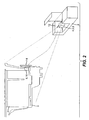
- FIG. 2 illustrates a printing apparatus 2 having an image-formation-material (“IFM”) reservoir 4 installed therein, according to an embodiment of the present invention.
- the IFM reservoir 4 may be an ink tank formed of polypropylene used in an ink jet printing apparatus, according to an embodiment of the present invention. While polypropylene is an advantageous material for forming an IFM reservoir 4 because of its cleanliness and compatibility with inks, one skilled in the art will appreciate that many other injection-moldable materials may be used to form the IFM reservoir 4.
- the IFM reservoir 4 is supported by a printhead chassis 5.
- the printhead chassis 5 and the IFM reservoir 4 are mounted on a carriage assembly 8 which moves in a lateral direction as image-forming-material is ejected to form an image on a substrate.
- a component such as a data-providing component 6 is retained by a securing mechanism 10.
- the data-providing component 6 is communicatively connected (via connector 14 on the carriage and a communicative connection represented by the curved dotted line) to a data processing system 12.
- Data processing system 12 is typically located within the body of the printing apparatus 2, and it interacts with the data-providing component 6 in order to at least monitor an operation of the IFM reservoir 4, according to an embodiment of the invention.
- the phrase "communicatively connected” is intended to include any type of connection, whether wired, wireless, or both, between devices, and/or data processing systems, and/or programs in which data may be communicated.
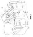
- FIG. 3 illustrates a close view of a securing mechanism 10 integrally formed with the IFM reservoir 4, according to an embodiment of the present invention.
- securing mechanism 10 may be formed during the same injection molding process as is used to fabricate the IFM reservoir 4.
- the securing mechanism 10 is integrally formed with the IFM reservoir 4 in FIG. 3 , one skilled in the art will appreciate that the securing mechanism 10 may instead be its own separate part attached to the IFM reservoir 4.
- the securing mechanism 10 includes a drawer-style support feature 16.
- the drawer-style support feature 16 includes a base surface 38 that supports an underneath of the data-providing component 6 (shown in FIG. 4 ).
- the drawer-style support feature 16 also includes two guiding regions 22 that interact with sides 42 of the data processing component 6 when such component 6 is inserted into the securing mechanism 10 in a direction 17.
- the guiding regions 22 include a fixed wall 24 and a spring wall 26.
- the spring wall 26 biases the data-providing component 6 against the fixed wall 24.
- the spring wall 26 has a dove tail shape.
- a retention feature 18 located at an opening end 20 of the drawer-style support feature 16 hooks around an end of the data-providing component 6 to lock such component 6 into its engaged position.
- the retention feature 18 is an engaging retention feature, such as a lip or hook 30.
- FIG. 4 illustrates the embodiment of FIG. 3 with the data-providing component 6 installed into the securing mechanism 10.
- the data-providing component has data contact pads 40 thereon that are used to form a communicative connection between the data providing component 6 and the data processing system 12 (not shown in FIG. 4 ).
- the sides 42 of the data-providing component 6 that interact with the guiding regions 22 of the securing mechanism 10.
- an end 44 of the data providing component 6 interacts with the stop datums 36.
- the securing mechanism 10 includes a release mechanism 34 that, upon application of a depression force, releases the data-providing component 6 from the securing mechanism 10 unharmed. Consequently, the data-providing component 6 may be reused upon removal from the securing mechanism 10.
- the securing mechanism 10, illustrated in the embodiment of FIGS. 3 and 4 may be used without an external bonding agent.
- the securing mechanism 10 can retain the data-providing component 6 in a mechanical manner, without external bonding agents, such as adhesive or solder.
- the securing mechanism 10 may include a release mechanism 34 that, upon application of a depression force, releases the data-providing component 6 from the securing mechanism 10 unharmed. Consequently, the data-providing component 6 may be reused upon removal from the securing mechanism 10.
- a non-permanent adhesive i.e., an adhesive that may be removed and does not damage the data providing component 6 or hinder its operability or use, may be used.
- nearly any external bonding agent may be used in addition to the securing mechanism 10.
- FIG. 5 illustrates a drawer-style support feature 16 of a securing mechanism 10 integrally formed with the IFM reservoir 4, according to another embodiment of the present invention.
- the securing mechanism 10 is integrally formed with the IFM reservoir 4 in FIG. 5 , one skilled in the art will appreciate that the securing mechanism 10 may instead be its own separate part attached to the IFM reservoir 4.
- the retention feature 18 at an opening end 20 of the drawer-style support feature 16 includes staked ends 32.
- the staked ends 32 form lips or hooks that wrap around the end of the data providing component 6 (not shown in FIG. 5 ).
- the staked ends may be molded into their staked position by heat and/or pressure after the data-providing component is inserted therein.
- the securing mechanism 10 may be formed of a material that is moldable at a low temperature, such as polypropylene.
- the staked ends 32 may be reheated and opened to allow the data-providing component 6 to be removed from the drawer-style support feature 16 unharmed.
- heating is referred to as a mechanism for molding the staked ends 32, one skilled in the art will appreciate that other techniques, such as cold staking or merely the application of pressure for molding a material, may be used.
- Printing apparatus 4 Image-formation-material ("IFM") reservoir 5 Printhead chassis 6 Component (RFID, smartchip) data storage device 8 Carriage assembly 10 Securing mechanism 12 Data processing system 14 Communicative connection between processing system and data storage device 16 Drawer-style support feature of securing mechanism 17 Insertion Direction 18 Engaging retention feature 20 Opening end of drawer-style support feature 22 Two guiding regions of securing mechanism 24 Fixed wall of securing mechanism 26 Spring wall of securing mechanism 30 Hook at end of securing mechanism 32 Lip at end of securing mechanism 34 Release mechanism of securing mechanism 36 Stop datum 38 Base surface 40 Data contact pads 42 Sides of component, interact with securing mechanism 44 End of component 102, 104 Ink tank 106, 108 Smartchip 110 Epoxy dot adhesive 112 Adhesive tape backing
Landscapes
- Ink Jet (AREA)
- Accessory Devices And Overall Control Thereof (AREA)
Applications Claiming Priority (2)
| Application Number | Priority Date | Filing Date | Title |
|---|---|---|---|
| US11/614,107 US7976138B2 (en) | 2006-12-21 | 2006-12-21 | Data-providing-component securing mechanism for printing apparatus reservoir |
| PCT/US2007/024887 WO2008088486A1 (en) | 2006-12-21 | 2007-12-05 | Data and securing mechanism for printing reservoir |
Publications (2)
| Publication Number | Publication Date |
|---|---|
| EP2091744A1 EP2091744A1 (en) | 2009-08-26 |
| EP2091744B1 true EP2091744B1 (en) | 2013-05-29 |
Family
ID=39431062
Family Applications (1)
| Application Number | Title | Priority Date | Filing Date |
|---|---|---|---|
| EP07862528.2A Not-in-force EP2091744B1 (en) | 2006-12-21 | 2007-12-05 | Data and securing mechanism for printing reservoir |
Country Status (5)
| Country | Link |
|---|---|
| US (1) | US7976138B2 (enExample) |
| EP (1) | EP2091744B1 (enExample) |
| JP (1) | JP2010513093A (enExample) |
| CN (1) | CN101622135B (enExample) |
| WO (1) | WO2008088486A1 (enExample) |
Families Citing this family (2)
| Publication number | Priority date | Publication date | Assignee | Title |
|---|---|---|---|---|
| US7721551B2 (en) * | 2006-06-29 | 2010-05-25 | United Technologies Corporation | Fan variable area nozzle for a gas turbine engine fan nacelle |
| CN103332015B (zh) * | 2013-07-05 | 2015-12-02 | 珠海艾派克微电子有限公司 | 一种芯片、成像盒及其响应成像装置的方法 |
Family Cites Families (16)
| Publication number | Priority date | Publication date | Assignee | Title |
|---|---|---|---|---|
| DE3884988T2 (de) * | 1987-03-27 | 1994-05-19 | Mitsubishi Electric Corp | Mechanismus zum Verbinden von Leiterplatten und externe Vorrichtung dafür. |
| US6499826B1 (en) * | 2000-01-05 | 2002-12-31 | Hewlett-Packard Company | Horizontally loadable carriage for an ink-jet printer |
| WO2002011986A2 (en) | 2000-08-07 | 2002-02-14 | Dynamic Cassette International Ltd. | A printer cartridge kit and method |
| GB2354202B (en) * | 2000-08-07 | 2002-09-18 | Dynamic Cassette Int | A printer cartridge kit and method |
| JP2002079674A (ja) | 2000-09-04 | 2002-03-19 | Canon Inc | 液体吐出ヘッドユニット、ヘッドカートリッジおよび液体吐出ヘッドユニットの製造方法 |
| CA2371040A1 (en) | 2001-02-09 | 2002-08-09 | Nobuyuki Hatasa | Liquid container and recording apparatus |
| US6505926B1 (en) | 2001-08-16 | 2003-01-14 | Eastman Kodak Company | Ink cartridge with memory chip and method of assembling |
| JP2003243070A (ja) * | 2002-02-20 | 2003-08-29 | Seiko Epson Corp | コネクタ、現像カートリッジ及び画像形成装置 |
| JP4301786B2 (ja) * | 2002-09-11 | 2009-07-22 | エステー産業株式会社 | 使用済みインクカートリッジのための再利用化用具 |
| JP2004174827A (ja) * | 2002-11-26 | 2004-06-24 | Brother Ind Ltd | インクジェットプリンタヘッド及びそのためのヘッドユニット |
| JP4630551B2 (ja) | 2003-02-14 | 2011-02-09 | 理想科学工業株式会社 | インク容器 |
| US7212637B2 (en) * | 2003-03-11 | 2007-05-01 | Rimage Corporation | Cartridge validation with radio frequency identification |
| US20060053030A1 (en) | 2004-09-07 | 2006-03-09 | Hiroto Nakamura | Method of recycling a liquid cartridge |
| US20060152561A1 (en) | 2004-12-31 | 2006-07-13 | Belfiore David A | Ink bag assembly |
| CN2931121Y (zh) | 2006-05-09 | 2007-08-08 | 聂瑞权 | 喷墨打印机墨盒芯片固定装置 |
| US7690774B2 (en) | 2006-12-21 | 2010-04-06 | Eastman Kodak Company | Printing device fluid reservoir with gripping features |
-
2006
- 2006-12-21 US US11/614,107 patent/US7976138B2/en not_active Expired - Fee Related
-
2007
- 2007-12-05 WO PCT/US2007/024887 patent/WO2008088486A1/en not_active Ceased
- 2007-12-05 CN CN2007800475047A patent/CN101622135B/zh not_active Expired - Fee Related
- 2007-12-05 EP EP07862528.2A patent/EP2091744B1/en not_active Not-in-force
- 2007-12-05 JP JP2009542784A patent/JP2010513093A/ja active Pending
Also Published As
| Publication number | Publication date |
|---|---|
| WO2008088486A1 (en) | 2008-07-24 |
| EP2091744A1 (en) | 2009-08-26 |
| JP2010513093A (ja) | 2010-04-30 |
| CN101622135A (zh) | 2010-01-06 |
| US20080151012A1 (en) | 2008-06-26 |
| US7976138B2 (en) | 2011-07-12 |
| CN101622135B (zh) | 2011-07-06 |
Similar Documents
| Publication | Publication Date | Title |
|---|---|---|
| US8220909B2 (en) | Ink bag adapter, adapter-equipped ink bag, and printing apparatus | |
| KR101896816B1 (ko) | 잉크 카트리지 및 잉크젯 프린터 | |
| KR20160035066A (ko) | 잉크 카트리지 및 잉크젯 프린터 | |
| US8057028B2 (en) | Printing device fluid reservoir with gripping features | |
| US20080204507A1 (en) | Fluid-ejection device service station | |
| JP2010083111A (ja) | インクカートリッジの着脱機構及び着脱制御方法 | |
| JP2010162867A (ja) | 液体吐出装置 | |
| RU2651259C1 (ru) | Наформованное устройство подачи чернил | |
| EP2091744B1 (en) | Data and securing mechanism for printing reservoir | |
| US7188925B2 (en) | Fluid ejection head assembly | |
| EP0622196A2 (en) | Slit nozzle tape for ink jet print head | |
| US8231192B2 (en) | Liquid detection unit, and liquid container using liquid detection unit | |
| US20140232770A1 (en) | Image forming device and image forming method | |
| JP3806092B2 (ja) | インクジェット印刷ヘッド用のスナウト封入キャッピング装置 | |
| JP3617213B2 (ja) | インクタンク、インクジェット記録ユニット、およびインクジェット記録装置 | |
| JP2006116786A (ja) | 液体収納容器および該容器用ホルダ | |
| US7837312B2 (en) | Liquid cartridge and method for manufacturing the same | |
| JP2017154292A (ja) | インクカートリッジの再生産方法 | |
| JP2006224424A (ja) | 液体噴射ヘッドおよび液体噴射装置 | |
| JP2007160714A (ja) | 液体噴射装置 | |
| JP2017154482A (ja) | インクカートリッジ | |
| US20090219341A1 (en) | Liquid ejection head and method of producing the same | |
| JP2004042417A (ja) | インクジェット記録装置 | |
| JPH1134342A (ja) | 配線材押え具 | |
| WO2007062603A1 (fr) | Cartouche d'encre amelioree et son procede de fabrication |
Legal Events
| Date | Code | Title | Description |
|---|---|---|---|
| PUAI | Public reference made under article 153(3) epc to a published international application that has entered the european phase |
Free format text: ORIGINAL CODE: 0009012 |
|
| 17P | Request for examination filed |
Effective date: 20090602 |
|
| AK | Designated contracting states |
Kind code of ref document: A1 Designated state(s): AT BE BG CH CY CZ DE DK EE ES FI FR GB GR HU IE IS IT LI LT LU LV MC MT NL PL PT RO SE SI SK TR |
|
| DAX | Request for extension of the european patent (deleted) | ||
| 17Q | First examination report despatched |
Effective date: 20120308 |
|
| GRAP | Despatch of communication of intention to grant a patent |
Free format text: ORIGINAL CODE: EPIDOSNIGR1 |
|
| GRAS | Grant fee paid |
Free format text: ORIGINAL CODE: EPIDOSNIGR3 |
|
| GRAA | (expected) grant |
Free format text: ORIGINAL CODE: 0009210 |
|
| AK | Designated contracting states |
Kind code of ref document: B1 Designated state(s): AT BE BG CH CY CZ DE DK EE ES FI FR GB GR HU IE IS IT LI LT LU LV MC MT NL PL PT RO SE SI SK TR |
|
| REG | Reference to a national code |
Ref country code: GB Ref legal event code: FG4D |
|
| REG | Reference to a national code |
Ref country code: CH Ref legal event code: EP |
|
| REG | Reference to a national code |
Ref country code: AT Ref legal event code: REF Ref document number: 614111 Country of ref document: AT Kind code of ref document: T Effective date: 20130615 |
|
| REG | Reference to a national code |
Ref country code: IE Ref legal event code: FG4D |
|
| REG | Reference to a national code |
Ref country code: DE Ref legal event code: R096 Ref document number: 602007030805 Country of ref document: DE Effective date: 20130725 |
|
| REG | Reference to a national code |
Ref country code: NL Ref legal event code: T3 |
|
| REG | Reference to a national code |
Ref country code: AT Ref legal event code: MK05 Ref document number: 614111 Country of ref document: AT Kind code of ref document: T Effective date: 20130529 |
|
| REG | Reference to a national code |
Ref country code: LT Ref legal event code: MG4D |
|
| PG25 | Lapsed in a contracting state [announced via postgrant information from national office to epo] |
Ref country code: SI Free format text: LAPSE BECAUSE OF FAILURE TO SUBMIT A TRANSLATION OF THE DESCRIPTION OR TO PAY THE FEE WITHIN THE PRESCRIBED TIME-LIMIT Effective date: 20130529 Ref country code: FI Free format text: LAPSE BECAUSE OF FAILURE TO SUBMIT A TRANSLATION OF THE DESCRIPTION OR TO PAY THE FEE WITHIN THE PRESCRIBED TIME-LIMIT Effective date: 20130529 Ref country code: ES Free format text: LAPSE BECAUSE OF FAILURE TO SUBMIT A TRANSLATION OF THE DESCRIPTION OR TO PAY THE FEE WITHIN THE PRESCRIBED TIME-LIMIT Effective date: 20130909 Ref country code: SE Free format text: LAPSE BECAUSE OF FAILURE TO SUBMIT A TRANSLATION OF THE DESCRIPTION OR TO PAY THE FEE WITHIN THE PRESCRIBED TIME-LIMIT Effective date: 20130529 Ref country code: LT Free format text: LAPSE BECAUSE OF FAILURE TO SUBMIT A TRANSLATION OF THE DESCRIPTION OR TO PAY THE FEE WITHIN THE PRESCRIBED TIME-LIMIT Effective date: 20130529 Ref country code: IS Free format text: LAPSE BECAUSE OF FAILURE TO SUBMIT A TRANSLATION OF THE DESCRIPTION OR TO PAY THE FEE WITHIN THE PRESCRIBED TIME-LIMIT Effective date: 20130929 Ref country code: PT Free format text: LAPSE BECAUSE OF FAILURE TO SUBMIT A TRANSLATION OF THE DESCRIPTION OR TO PAY THE FEE WITHIN THE PRESCRIBED TIME-LIMIT Effective date: 20130930 Ref country code: AT Free format text: LAPSE BECAUSE OF FAILURE TO SUBMIT A TRANSLATION OF THE DESCRIPTION OR TO PAY THE FEE WITHIN THE PRESCRIBED TIME-LIMIT Effective date: 20130529 Ref country code: GR Free format text: LAPSE BECAUSE OF FAILURE TO SUBMIT A TRANSLATION OF THE DESCRIPTION OR TO PAY THE FEE WITHIN THE PRESCRIBED TIME-LIMIT Effective date: 20130830 |
|
| PG25 | Lapsed in a contracting state [announced via postgrant information from national office to epo] |
Ref country code: BG Free format text: LAPSE BECAUSE OF FAILURE TO SUBMIT A TRANSLATION OF THE DESCRIPTION OR TO PAY THE FEE WITHIN THE PRESCRIBED TIME-LIMIT Effective date: 20130829 Ref country code: PL Free format text: LAPSE BECAUSE OF FAILURE TO SUBMIT A TRANSLATION OF THE DESCRIPTION OR TO PAY THE FEE WITHIN THE PRESCRIBED TIME-LIMIT Effective date: 20130529 |
|
| PG25 | Lapsed in a contracting state [announced via postgrant information from national office to epo] |
Ref country code: LV Free format text: LAPSE BECAUSE OF FAILURE TO SUBMIT A TRANSLATION OF THE DESCRIPTION OR TO PAY THE FEE WITHIN THE PRESCRIBED TIME-LIMIT Effective date: 20130529 |
|
| PG25 | Lapsed in a contracting state [announced via postgrant information from national office to epo] |
Ref country code: SK Free format text: LAPSE BECAUSE OF FAILURE TO SUBMIT A TRANSLATION OF THE DESCRIPTION OR TO PAY THE FEE WITHIN THE PRESCRIBED TIME-LIMIT Effective date: 20130529 Ref country code: BE Free format text: LAPSE BECAUSE OF FAILURE TO SUBMIT A TRANSLATION OF THE DESCRIPTION OR TO PAY THE FEE WITHIN THE PRESCRIBED TIME-LIMIT Effective date: 20130529 Ref country code: DK Free format text: LAPSE BECAUSE OF FAILURE TO SUBMIT A TRANSLATION OF THE DESCRIPTION OR TO PAY THE FEE WITHIN THE PRESCRIBED TIME-LIMIT Effective date: 20130529 Ref country code: CZ Free format text: LAPSE BECAUSE OF FAILURE TO SUBMIT A TRANSLATION OF THE DESCRIPTION OR TO PAY THE FEE WITHIN THE PRESCRIBED TIME-LIMIT Effective date: 20130529 Ref country code: EE Free format text: LAPSE BECAUSE OF FAILURE TO SUBMIT A TRANSLATION OF THE DESCRIPTION OR TO PAY THE FEE WITHIN THE PRESCRIBED TIME-LIMIT Effective date: 20130529 |
|
| PGFP | Annual fee paid to national office [announced via postgrant information from national office to epo] |
Ref country code: GB Payment date: 20131001 Year of fee payment: 7 |
|
| PG25 | Lapsed in a contracting state [announced via postgrant information from national office to epo] |
Ref country code: RO Free format text: LAPSE BECAUSE OF FAILURE TO SUBMIT A TRANSLATION OF THE DESCRIPTION OR TO PAY THE FEE WITHIN THE PRESCRIBED TIME-LIMIT Effective date: 20130529 Ref country code: IT Free format text: LAPSE BECAUSE OF FAILURE TO SUBMIT A TRANSLATION OF THE DESCRIPTION OR TO PAY THE FEE WITHIN THE PRESCRIBED TIME-LIMIT Effective date: 20130529 |
|
| PLBE | No opposition filed within time limit |
Free format text: ORIGINAL CODE: 0009261 |
|
| STAA | Information on the status of an ep patent application or granted ep patent |
Free format text: STATUS: NO OPPOSITION FILED WITHIN TIME LIMIT |
|
| 26N | No opposition filed |
Effective date: 20140303 |
|
| REG | Reference to a national code |
Ref country code: DE Ref legal event code: R097 Ref document number: 602007030805 Country of ref document: DE Effective date: 20140303 |
|
| REG | Reference to a national code |
Ref country code: CH Ref legal event code: PL |
|
| PG25 | Lapsed in a contracting state [announced via postgrant information from national office to epo] |
Ref country code: LU Free format text: LAPSE BECAUSE OF FAILURE TO SUBMIT A TRANSLATION OF THE DESCRIPTION OR TO PAY THE FEE WITHIN THE PRESCRIBED TIME-LIMIT Effective date: 20131205 Ref country code: MC Free format text: LAPSE BECAUSE OF FAILURE TO SUBMIT A TRANSLATION OF THE DESCRIPTION OR TO PAY THE FEE WITHIN THE PRESCRIBED TIME-LIMIT Effective date: 20130529 |
|
| REG | Reference to a national code |
Ref country code: IE Ref legal event code: MM4A |
|
| REG | Reference to a national code |
Ref country code: FR Ref legal event code: ST Effective date: 20140829 |
|
| PG25 | Lapsed in a contracting state [announced via postgrant information from national office to epo] |
Ref country code: IE Free format text: LAPSE BECAUSE OF NON-PAYMENT OF DUE FEES Effective date: 20131205 Ref country code: LI Free format text: LAPSE BECAUSE OF NON-PAYMENT OF DUE FEES Effective date: 20131231 Ref country code: CH Free format text: LAPSE BECAUSE OF NON-PAYMENT OF DUE FEES Effective date: 20131231 |
|
| PG25 | Lapsed in a contracting state [announced via postgrant information from national office to epo] |
Ref country code: FR Free format text: LAPSE BECAUSE OF NON-PAYMENT OF DUE FEES Effective date: 20131231 |
|
| PG25 | Lapsed in a contracting state [announced via postgrant information from national office to epo] |
Ref country code: TR Free format text: LAPSE BECAUSE OF FAILURE TO SUBMIT A TRANSLATION OF THE DESCRIPTION OR TO PAY THE FEE WITHIN THE PRESCRIBED TIME-LIMIT Effective date: 20130529 Ref country code: CY Free format text: LAPSE BECAUSE OF FAILURE TO SUBMIT A TRANSLATION OF THE DESCRIPTION OR TO PAY THE FEE WITHIN THE PRESCRIBED TIME-LIMIT Effective date: 20130529 |
|
| PG25 | Lapsed in a contracting state [announced via postgrant information from national office to epo] |
Ref country code: HU Free format text: LAPSE BECAUSE OF FAILURE TO SUBMIT A TRANSLATION OF THE DESCRIPTION OR TO PAY THE FEE WITHIN THE PRESCRIBED TIME-LIMIT; INVALID AB INITIO Effective date: 20071205 |
|
| GBPC | Gb: european patent ceased through non-payment of renewal fee |
Effective date: 20141205 |
|
| PG25 | Lapsed in a contracting state [announced via postgrant information from national office to epo] |
Ref country code: MT Free format text: LAPSE BECAUSE OF FAILURE TO SUBMIT A TRANSLATION OF THE DESCRIPTION OR TO PAY THE FEE WITHIN THE PRESCRIBED TIME-LIMIT Effective date: 20130529 |
|
| PG25 | Lapsed in a contracting state [announced via postgrant information from national office to epo] |
Ref country code: GB Free format text: LAPSE BECAUSE OF NON-PAYMENT OF DUE FEES Effective date: 20141205 |
|
| PGFP | Annual fee paid to national office [announced via postgrant information from national office to epo] |
Ref country code: NL Payment date: 20161207 Year of fee payment: 10 |
|
| PGFP | Annual fee paid to national office [announced via postgrant information from national office to epo] |
Ref country code: DE Payment date: 20161220 Year of fee payment: 10 |
|
| REG | Reference to a national code |
Ref country code: DE Ref legal event code: R119 Ref document number: 602007030805 Country of ref document: DE |
|
| REG | Reference to a national code |
Ref country code: NL Ref legal event code: MM Effective date: 20180101 |
|
| PG25 | Lapsed in a contracting state [announced via postgrant information from national office to epo] |
Ref country code: NL Free format text: LAPSE BECAUSE OF NON-PAYMENT OF DUE FEES Effective date: 20180101 |
|
| PG25 | Lapsed in a contracting state [announced via postgrant information from national office to epo] |
Ref country code: DE Free format text: LAPSE BECAUSE OF NON-PAYMENT OF DUE FEES Effective date: 20180703 |