EP2089963B1 - Alimentation a deux onduleurs en serie pour actionneur electromecanique polyphase - Google Patents
Alimentation a deux onduleurs en serie pour actionneur electromecanique polyphase Download PDFInfo
- Publication number
- EP2089963B1 EP2089963B1 EP07871808A EP07871808A EP2089963B1 EP 2089963 B1 EP2089963 B1 EP 2089963B1 EP 07871808 A EP07871808 A EP 07871808A EP 07871808 A EP07871808 A EP 07871808A EP 2089963 B1 EP2089963 B1 EP 2089963B1
- Authority
- EP
- European Patent Office
- Prior art keywords
- arms
- switches
- windings
- inverter
- power supply
- Prior art date
- Legal status (The legal status is an assumption and is not a legal conclusion. Google has not performed a legal analysis and makes no representation as to the accuracy of the status listed.)
- Active
Links
Images


Classifications
-
- H—ELECTRICITY
- H02—GENERATION; CONVERSION OR DISTRIBUTION OF ELECTRIC POWER
- H02M—APPARATUS FOR CONVERSION BETWEEN AC AND AC, BETWEEN AC AND DC, OR BETWEEN DC AND DC, AND FOR USE WITH MAINS OR SIMILAR POWER SUPPLY SYSTEMS; CONVERSION OF DC OR AC INPUT POWER INTO SURGE OUTPUT POWER; CONTROL OR REGULATION THEREOF
- H02M7/00—Conversion of AC power input into DC power output; Conversion of DC power input into AC power output
- H02M7/42—Conversion of DC power input into AC power output without possibility of reversal
- H02M7/44—Conversion of DC power input into AC power output without possibility of reversal by static converters
- H02M7/48—Conversion of DC power input into AC power output without possibility of reversal by static converters using discharge tubes with control electrode or semiconductor devices with control electrode
- H02M7/53—Conversion of DC power input into AC power output without possibility of reversal by static converters using discharge tubes with control electrode or semiconductor devices with control electrode using devices of a triode or transistor type requiring continuous application of a control signal
- H02M7/537—Conversion of DC power input into AC power output without possibility of reversal by static converters using discharge tubes with control electrode or semiconductor devices with control electrode using devices of a triode or transistor type requiring continuous application of a control signal using semiconductor devices only, e.g. single switched pulse inverters
- H02M7/5387—Conversion of DC power input into AC power output without possibility of reversal by static converters using discharge tubes with control electrode or semiconductor devices with control electrode using devices of a triode or transistor type requiring continuous application of a control signal using semiconductor devices only, e.g. single switched pulse inverters in a bridge configuration
-
- H—ELECTRICITY
- H02—GENERATION; CONVERSION OR DISTRIBUTION OF ELECTRIC POWER
- H02P—CONTROL OR REGULATION OF ELECTRIC MOTORS, ELECTRIC GENERATORS OR DYNAMO-ELECTRIC CONVERTERS; CONTROLLING TRANSFORMERS, REACTORS OR CHOKE COILS
- H02P27/00—Arrangements or methods for the control of AC motors characterised by the kind of supply voltage
- H02P27/04—Arrangements or methods for the control of AC motors characterised by the kind of supply voltage using variable-frequency supply voltage, e.g. inverter or converter supply voltage
- H02P27/06—Arrangements or methods for the control of AC motors characterised by the kind of supply voltage using variable-frequency supply voltage, e.g. inverter or converter supply voltage using DC to AC converters or inverters
-
- H—ELECTRICITY
- H02—GENERATION; CONVERSION OR DISTRIBUTION OF ELECTRIC POWER
- H02P—CONTROL OR REGULATION OF ELECTRIC MOTORS, ELECTRIC GENERATORS OR DYNAMO-ELECTRIC CONVERTERS; CONTROLLING TRANSFORMERS, REACTORS OR CHOKE COILS
- H02P29/00—Arrangements for regulating or controlling electric motors, appropriate for both AC and DC motors
- H02P29/02—Providing protection against overload without automatic interruption of supply
- H02P29/032—Preventing damage to the motor, e.g. setting individual current limits for different drive conditions
Definitions
- the invention relates to a two-inverter power supply in series for a polyphase electromechanical actuator.
- each inverter has a source of electrical voltage across which extend as many arms as there are windings to feed the machine.
- Each arm comprises an upstream controlled switch and a downstream controlled switch placed in series.
- Each winding comprises a first end connected to an arm of one of the inverters, at a point situated between the switches controlled by said arm, and a second end connected to an arm of the other inverter, also at a point situated between the controlled switches. of said arm.
- Such an architecture is therefore resistant to the failure of one of the controlled switches.
- such an architecture does not allow to continue to operate the rotating machine correctly if the end of one of the windings is disconnected from the corresponding arm. For example, on a three-phase rotating machine whose one of the windings is disconnected, it would then remain two controllable phases. If we continue to control the switches of the inverters as if one of the windings were not disconnected, we would impose on the machine a strongly corrugated torque, very detrimental for certain applications, for example the actuation of high-lift devices. an aircraft, or the actuation of undercarriages.
- the object of the invention is to improve the power supply to two inverters in series making it possible to continue operating the actuator in an acceptable manner in the event of failure of one of the switches, but also in other failure circumstances.
- a two-inverter power supply is proposed in series to power an electromechanical actuator having at least one electric motor comprising a plurality of phase-forming windings, each inverter being connected to a clean ground and having a a source of electrical voltage across which extend as many arms as there are windings to feed, each arm having two controlled switches placed in series between which is provided a connection point at one end of one of the windings.
- each inverter comprises an additional arm comprising two controlled switches, the two additional arms being interconnected by a bridge connected to each additional arm at a point between the switches.
- the controlled switches of the additional arms are kept open, so that the additional arms and the bridge have no effect on the operation of the actuator.
- the power supply can be reconfigured to cope with the failure of a switch, in a manner known per se.
- the valid phases can be fed with currents whose sum is not constantly zero so as to run the engine under constant torque.
- the residual current from the non-zero sum of the currents of the valid phases is drained by the bridge to be returned to the inverter which generates these currents. The presence of the bridge and additional arms therefore allows operation of the constant torque actuator.
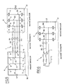
- the power architecture is here illustrated in application to an electromechanical actuator provided with an electric motor or three-phase rotating machine 1 which can be seen the three windings R1, R2, R3, each symbolically represented as a resistor, an inductor and a counter electromotive force in series.
- Each of the windings forms one of the phases of the rotating machine, and here it is spatially offset by 2 ⁇ / 3 with respect to the other windings.
- the power supply of the invention illustrated here comprises a first converter or inverter A and a second converter or inverter B.
- the inverter A comprises a first voltage source U1, one of whose terminals is connected to a first 50. At the terminals of the first voltage source U1 extend three arms A1, A2, A3 each comprising an upstream controlled switch 5 and a downstream controlled switch 6 placed in series on the arm.
- the controlled switches 5.6 fitted to the inverters A, B are, for example, junction bipolar transistors, metal-oxide-semiconductor field-effect transistors, thyristors controlled at the opening, or isolated-gate transistors.
- the winding R1 (respectively R2, R3) has a first end connected to the arm A1 (respectively A2, A3) at a point between the corresponding controlled switches 5,6.
- the inverter B comprises a second voltage source U2 having a terminal connected to a second ground 51, independent of the first ground 50.
- a second voltage source U2 having a terminal connected to a second ground 51, independent of the first ground 50.
- At the terminals of the second voltage source U2 extend three arms B1, B2, B3 each comprising an upstream controlled switch 5 and a downstream controlled switch 6 placed in series on the arm.
- the winding R1 (respectively R2, R3) has a second end connected to the arm B1 (respectively B2, B3) at a point between the corresponding controlled switches 5,6.
- each of the windings R1, R2, R3 is connected in series to one of the arms of the first inverter A, and to one of the arms of the second inverter B.
- the switches are controlled 5,6 so as to circulate in the windings R1, R2, R3 currents out of phase by 2 ⁇ / 3 (whose sum is constantly zero). This imposes on the rotating machine a constant torque.
- the machine can be controlled either with the first inverter A, or with the aid of the second inverter B, or with the aid of the two inverters operating simultaneously and synchronously.
- This type of power supply can be found on an aircraft comprising two totally independent power circuits having separate masses.
- the first inverter A further comprises an additional arm A4, similar in all respects to the arms A1, A2, A3.
- the second inverter B comprises an additional arm B4, similar in all respects to the arms B1, B2, B3.
- the additional arms A4, B4 are connected by a bridge 7 connected to each of the additional arms A4, B4 at a point between the controlled switches 5,6. In normal operation, the controlled switches 5.6 of the additional arms A4, B4 are kept open, so that neither the additional arms nor the bridge 7 disturb the operation of the rotating machine.
- switches which are locked in the closed position or which are deliberately kept in the closed state are represented by an electrical junction.
- switches that are locked in the open position or are voluntarily held in the open state are represented by an open circuit portion.
- one of the switches 5,6 of one of the arms A1, A2, A3 of the first inverter A fails.
- the downstream switch 6 of the arm A1 remains locked in the closed position due to a failure.
- the three phases are therefore controllable by circulating through the controlled switches 5.6 of the second inverter B currents out of phase by 2 ⁇ / 3 in the windings R1, R2, R3.
- the first inverter A is completely neutralized, and can not influence the control of the rotating machine by the second inverter B.
- the potential of the common point N certainly depends on the potential imposed by the voltage source U1, but can not be imposed by the voltage source U2. From the point of view of the second inverter B, the common point N therefore has a floating potential. It is therefore possible to supply each of the phases with phase-shifted currents of 2 ⁇ / 3, so that their sum is constantly zero.
- the torque of the rotating machine thus fed remains constant and equal to the nominal torque before failure of the switch.
- the speed thus generated is divided by two. To regain the initial speed, the voltage U2 should be increased accordingly.
- one of the windings can be disconnected from one of the arms.
- the winding R1 is disconnected from the arm A1 of the first inverter A, as symbolically represented. It is therefore no longer possible to feed the corresponding phase.
- the previous strategies do not apply here.
- the currents i2 and i3 supplying the valid phases (windings R2 and R3), as well as the current I drained by the bridge 7. It can be shown that the rotating machine thus fed develops a constant torque, but this torque equals 57% of the torque that it would have been possible to develop if one of the windings had not disconnected.
- a common point N is created between the valid phases and the bridge 7.
- the downstream switches 6 of the remaining arms A2, A3 and the downstream switch 6 of the additional arms A4 are closed.
- the upstream switches 5 of the arms A1, A2, A3 are kept open, as is the upstream switch 5 of the additional arm A4.
- the first inverter A is thus neutralized.
- the bridge 7 and the two valid windings R2 and R3 now have one end in common.
- the rotating machine of the actuator can be controlled using of a single inverter.
- the developed torque is constant and is equal to 57% of the nominal torque.
- the speed of rotation is, at constant voltage U2, divided by two. To regain the nominal rotation speed, the voltage U2 should be increased accordingly.
- the illustrated power architecture is therefore able to withstand the failure of one of the switches of the arms of the inverters, and the disconnection of one of the windings of the rotating machine.
- the invention is not limited to supplying an electromechanical actuator comprising a three-phase rotating machine, but applies to a polyphase machine that may have more than three phases.
Landscapes
- Engineering & Computer Science (AREA)
- Power Engineering (AREA)
- Control Of Ac Motors In General (AREA)
- Control Of Multiple Motors (AREA)
- Control Of Electric Motors In General (AREA)
- Coupling Device And Connection With Printed Circuit (AREA)
- Variable-Direction Aerials And Aerial Arrays (AREA)
- Inverter Devices (AREA)
Description
- L'invention concerne une alimentation à deux onduleurs en série pour actionneur électromécanique polyphasé.
- Pour alimenter un actionneur électromécanique dont le moteur polyphasé comporte des enroulements formant des phases, on connaît des alimentations comportant deux onduleurs placés en série. Une telle architecture est décrite par exemple par le document
FR-A-2 865 868 - Si sur l'un des bras de l'un des onduleurs, l'un des interrupteurs commandés vient à défaillir, qu'il reste ouvert ou fermé, il est connu de fermer certains interrupteurs de l'onduleur concernés et d'ouvrir les autres interrupteurs de façon à créer un point commun entre les extrémités des enroulements reliées à cet onduleur, ce point commun étant relié à l'une des bornes de la source de tension. Comme les deux sources de tension sont reliées à deux masses distinctes, le point commun est neutre du point de vue de l'autre onduleur, et il devient ainsi possible de commander la machine uniquement avec l'autre onduleur, et ainsi continuer à assurer un fonctionnement de la machine tournante avec un couple sensiblement constant.
- Une telle architecture est donc résistante à la défaillance de l'un des interrupteurs commandés. Cependant, une telle architecture ne permet pas de continuer à faire fonctionner de façon correcte la machine tournante si l'extrémité de l'un des enroulements vient à se déconnecter du bras correspondant. Par exemple, sur une machine tournante triphasée dont l'un des enroulements est déconnecté, il resterait alors deux phases commandables. Si l'on continue à commander les interrupteurs des onduleurs comme si l'un des enroulements n'était pas déconnecté, on imposerait à la machine un couple fortement ondulé, très préjudiciable pour certaines applications, par exemple l'actionnement des dispositifs hypersustentateurs d'un aéronef, ou l'actionnement d'atterrisseurs.
- On peut, comme auparavant, chercher à créer un point commun entre les deux phases valides, en ouvrant et fermant les interrupteurs de l'un des onduleurs de façon adéquate. Cependant, ces deux phases ainsi reliées par un point commun ne pourraient être commandées qu'avec des courants de somme nulle, qui devraient donc être déphasés d'un angle π, ce qui, combiné au déphasage spatial des phases de 2π/3, conduirait également à un couple fortement ondulé.
- L'invention a pour objet une amélioration de l'alimentation à deux onduleurs en série permettant de continuer à faire fonctionner l'actionneur de façon acceptable en cas de panne d'un des interrupteurs, mais également dans d'autres circonstances de panne.
- En vue de la réalisation de ce but, on propose une alimentation à deux onduleurs en série pour alimenter un actionneur électromécanique ayant au moins un moteur électrique comportant une pluralité d'enroulements formant des phases, chaque onduleur étant relié à une masse propre et comportant une source de tension électrique aux bornes de laquelle s'étendent autant de bras qu'il y a d'enroulements à alimenter, chaque bras comportant deux interrupteurs commandés placés en série entre lesquels est prévu un point de liaison à une extrémité d'un des enroulements. Selon l'invention, chaque onduleur comporte un bras supplémentaire comportant deux interrupteurs commandés, les deux bras supplémentaires étant reliés entre eux par un pont connecté à chaque bras supplémentaire en un point situé entre les interrupteurs.
- Ainsi, en temps normal, les interrupteurs commandés des bras supplémentaires sont maintenus ouverts, de sorte que les bras supplémentaires et le pont n'ont aucune incidence sur le fonctionnement de l'actionneur. L'alimentation peut être reconfigurée pour faire face à la défaillance d'un interrupteur, de façon connue en soi.
- Si l'un des enroulements venait à se déconnecter de l'un des bras, de sorte que la phase correspondante ne peut plus être commandée, on peut alimenter les phases valides avec des courants dont la somme n'est pas constamment nulle de façon à faire tourner le moteur sous un couple constant. Le courant résiduel provenant de la somme non nulle des courants des phases valides est drainé par le pont pour être renvoyé vers l'onduleur qui génère ces courants. La présence du pont et des bras supplémentaires permet donc un fonctionnement de l'actionneur à couple constant.
- En particulier, dans le cas d'un moteur triphasé dont l'une des phases est déconnectée, on peut, en commandant les interrupteurs, créer un point commun entre les deux phases valides et le pont, ce qui permet un fonctionnement diphasé à couple constant de l'actionneur: en prévoyant des courants d'alimentation déphasés de π/3, alors que les phases sont spatialement déphasées d'un angle égal à 2π/3, on obtient un couple constant. Ainsi, on peut continuer à fonctionner à couple constant, même si l'une des phases est déconnectée.
- L'invention sera mieux comprise à la lumière de la description qui suit en référence aux figures des dessins annexés parmi lesquelles :
- la
figure 1 est une vue schématique d'une alimentation à deux onduleurs en série pour un actionneur équipé d'un moteur électrique triphasé, selon un mode particulier de réalisation de l'invention ; - la
figure 2 est une vue analogue à lafigure 1 , illustrant une situation de panne dans laquelle l'un des interrupteurs est bloqué en position fermée ; - la
figure 3 est un schéma équivalent de celui de lafigure 2 , n'illustrant que les bras fonctionnels; - la
figure 4 est une vue analogue à lafigure 1 , illustrant une situation de panne dans laquelle l'un des enroulements du moteur est déconnecté de l'un des bras; - la
figure 5 est une vue analogue à lafigure 4 , illustrant une deuxième façon de gérer une déconnexion de phase; - la
figure 6 est un schéma équivalent de celui de lafigure 5 , n'illustrant que les bras fonctionnels. - En référence à la
figure 1 , l'architecture d'alimentation est ici illustrée en application à un actionneur électromécanique pourvu d'un moteur électrique ou machine tournante triphasée 1 dont on aperçoit les trois enroulements R1,R2,R3, symbolisés chacun de façon classique à une résistance, une inductance et une force contre-électromotrice en série. Chacun des enroulements forme l'une des phases de la machine tournante, et est ici spatialement décalé de 2π/3 par rapport aux autres enroulements. L'alimentation de l'invention illustrée ici comporte un premier convertisseur ou onduleur A et un deuxième convertisseur ou onduleur B. - L'onduleur A comporte une première source de tension U1 dont une des bornes est reliée à une première masse 50. Aux bornes de la première source de tension U1 s'étendent trois bras A1,A2,A3 comportant chacun un interrupteur commandé amont 5 et un interrupteur commandé aval 6 placés en série sur le bras. Les interrupteurs commandés 5,6 équipant les onduleurs A,B sont par exemple des transistors bipolaires à jonction, des transistors à effet de champ Metal-Oxyde-semiconducteur, des thyristors commandés à l'ouverture, ou encore des transistors à grille isolée.
- L'enroulement R1 (respectivement R2,R3) comporte une première extrémité reliée au bras A1 (respectivement A2, A3) en un point situé entre les interrupteurs commandés 5,6 correspondants.
- De même, L'onduleur B comporte une seconde source de tension U2 ayant une borne reliée à une seconde masse 51, indépendante de la première masse 50. Aux bornes de la seconde source de tension U2 s'étendent trois bras B1, B2, B3 comportant chacun un interrupteur commandé amont 5 et un interrupteur commandé aval 6 placés en série sur le bras.
- L'enroulement R1 (respectivement R2,R3) comporte une seconde extrémité reliée au bras B1 (respectivement B2,B3) en un point situé entre les interrupteurs commandés 5,6 correspondants.
- Ainsi, chacun des enroulements R1,R2,R3 est relié en série à l'un des bras du premier onduleur A, et à l'un des bras du second onduleur B. De façon connue en soi, on commande les interrupteurs 5,6 de façon à faire circuler dans les enroulements R1,R2,R3 des courants déphasés de 2π/3 (dont la somme est constamment nulle). On impose ainsi à la machine tournante un couple constant. On peut commander la machine soit à l'aide du premier onduleur A, soit à l'aide du seconde onduleur B, soit à l'aide des deux onduleurs fonctionnant simultanément et de façon synchronisée.
- Ce type d'alimentation peut se rencontrer sur un aéronef comportant deux circuits d'alimentation totalement indépendants, ayant des masses distinctes. Alternativement, et de façon connue en soi, il est possible de créer un deuxième circuit d'alimentation à partir d'un premier circuit d'alimentation au moyen d'un transformateur d'isolement, ou encore d'une alimentation à découpage isolée.
- Selon l'invention, le premier onduleur A comporte en outre un bras supplémentaire A4, en tout point similaire aux bras A1,A2,A3. De même, le second onduleur B comporte un bras supplémentaire B4, en tout point similaire aux bras B1,B2,B3. Les bras supplémentaires A4,B4, sont reliés par un pont 7 connecté à chacun des bras supplémentaires A4,B4 en un point situé entre les interrupteurs commandés 5,6. En fonctionnement normal, les interrupteurs commandés 5,6 des bras supplémentaires A4,B4 sont maintenus ouverts, de sorte que ni les bras supplémentaires ni le pont 7 ne perturbent le fonctionnement de la machine tournante.
- Dans les figures suivantes, sont illustrés différents modes de pannes et les façons de les traiter. Sur ces figures, les interrupteurs qui sont bloqués en position fermée ou qui sont maintenus volontairement dans l'état fermé sont représentés par une jonction électrique. Les interrupteurs qui sont bloqués en position ouverte ou qui sont maintenus volontairement dans l'état ouvert sont représentés par une portion de circuit ouvert.
- Selon un premier mode de panne, il se peut que l'une des interrupteurs 5,6 de l'un des bras A1,A2,A3 du premier onduleur A vienne à défaillir. Par exemple, comme cela est illustré à la
figure 2 , on suppose que l'interrupteur aval 6 du bras A1 reste bloqué en position fermée par suite d'une défaillance. - On peut bien sûr penser à neutraliser la phase correspondante en cessant de l'alimenter. Mais il est possible de continuer à utiliser les trois phases selon le procédé suivant : il suffit de maintenir fermés les interrupteurs aval 6 des bras A2 et A3, et d'ouvrir les interrupteurs amont 5 des bras A1,A2,A3. On crée ainsi un point commun N entre les extrémités des enroulements R1,R2,R3 du côté de l'onduleur A. Les liaisons réalisant ce point commun N sont surlignées en traits gras. Tout se passe comme si l'architecture d'alimentation avait la forme illustrée à la
figure 3 . - Les trois phases restent dès lors commandables en faisant circuler grâce aux interrupteurs commandés 5,6 du second onduleur B des courants déphasés de 2π/3 dans les enroulements R1, R2, R3. Le premier onduleur A est complètement neutralisé, et ne peut influencer la commande de la machine tournante par le second onduleur B. En particulier, le potentiel du point commun N dépend certes du potentiel imposé par la source de tension U1, mais ne peut être imposé par la source de tension U2. Du point de vue du second onduleur B, le point commun N a donc un potentiel flottant. Il est dès lors possible d'alimenter chacune des phases avec des courants déphasés de 2π/3, de sorte que leur somme soit constamment nulle. Combiné au déphasage spatial de zπ/3, le couple de la machine tournante ainsi alimentée reste constant et égal au couple nominal avant défaillance de l'interrupteur. Bien sûr, à tension U2 constante, la vitesse ainsi générée est divisée par deux. Pour retrouver la vitesse initiale, il convient d'augmenter en conséquence la tension U2.
- Si l'un des interrupteurs aval 6 de l'un des bras A1,A2,A3 du premier onduleur A devait être bloqué en position ouverte, alors il suffit de maintenir ouverts les autres interrupteurs aval 6 desdits bras, et de maintenir fermés les interrupteurs amont 5 desdits bras. On recrée de la même façon un point commun entre les phases, de sorte que la machine tournante reste parfaitement commandable.
- Les même remèdes s'appliquent lorsque l'un des interrupteurs amont 6 des bras A1,A2,A3 du premier onduleur A reste bloqué en position ouverte ou en position fermée. De la même façon, les mêmes remèdes s'appliquent si l'un des interrupteurs 5,6 des bras B1,B2,B3 du second onduleur B reste bloqué.
- Dans ces cas de panne, les interrupteurs des bras supplémentaires A4 et B4 sont maintenus ouverts, de sorte que les bras supplémentaires ne sont pas utilisés pour résoudre lesdits cas de pannes.
- Selon un autre cas de panne, l'un des enroulements peut être déconnecté de l'un des bras. Comme illustré à la
figure 4 , on suppose ici un cas de panne dans lequel l'enroulement R1 est déconnecté du bras A1 du premier onduleur A, comme symboliquement représenté. Il n'est dès lors plus possible d'alimenter la phase correspondante. Les stratégies précédentes ne trouvent donc pas à s'appliquer ici. - Par souci de sécurité, il convient tout d'abord d'isoler l'enroulement R1 déconnecté en ouvrant ici les interrupteurs 5,6 des bras A1 et B1 associés à cet enroulement, pour éviter tout risque de court-circuit entre les onduleurs par l'enroulement défaillant.
- Selon une première stratégie, on commande les interrupteurs des bras A2, A3, B2, B3 et des bras supplémentaires A4,B4 pour faire circuler dans les enroulements valides R2 et R3 des courants i2, i3 déphasés de π/3. Dès lors, la somme des courants i2, i3 n'est pas constamment nulle. Cependant, le reliquat de courant I=i2+i3 est collecté par le pont 7 et peut s'échapper par ce dernier pour revenir vers l'onduleur qui a généré les courants i2 et i3. Un tel fonctionnement donne lieu à un couple constant. On a illustré à la
figure 4 les courants i2 et i3 alimentant les phases valides (enroulements R2 et R3), ainsi que le courant I drainé par le pont 7. On peut démontrer que la machine tournante ainsi alimentée développe un couple constant, mais ce couple équivaut à 57% du couple qu'il aurait été possible de développer si l'un des enroulements ne s'était pas déconnecté. - Si l'on veut récupérer le couple nominal, il convient d'augmenter le courant d'alimentation en conséquence. Dans ce mode de fonctionnement, la vitesse de rotation de l'actionneur est égale à la vitesse de rotation nominale.
- Selon une deuxième stratégie illustrée aux
figures 5 et 6 , on crée un point commun N entre les phases valides et le pont 7. A cet effet, on maintient fermés les interrupteurs aval 6 des bras restants A2,A3, ainsi que l'interrupteur aval 6 du bras supplémentaires A4. On maintient ouverts les interrupteurs amont 5 des bras A1, A2, A3, ainsi que l'interrupteur amont 5 du bras supplémentaire A4. On crée ainsi un point commun N entre les extrémités des enroulements R2,R3, et le pont 7. Le premier onduleur A est ainsi neutralisé. - Comme illustré à la
figure 5 , le pont 7 et les deux enroulements valides R2 et R3 ont maintenant une extrémité en commun. On commande les interrupteurs des bras B2,B3 et du bras supplémentaire B4 du second onduleur B pour faire circuler dans les enroulements valides R2 et R3 des courants i2, i3 déphasés de π/3. Dès lors, la somme des courants i2, i3 n'est pas constamment nulle. Cependant, le reliquat de courant I=i2+i3 est collecté au point commun N et peut s'échapper par le pont 7 pour revenir vers le second onduleur B. Ainsi, on peut commander la machine tournante de l'actionneur à l'aide d'un seul onduleur. Ici également, le couple développé est constant et est égal à 57% du couple nominal. Par contre, la vitesse de rotation est, à tension U2 constante, divisée par deux. Pour retrouver la vitesse de rotation nominale, il convient d'augmenter la tension U2 en conséquence. - Sans les bras supplémentaires A4,B4, et sans le pont 7, il aurait été impossible d'alimenter les enroulements valides R2 et R3 avec des courants déphasés de π/3. Il aurait fallu assurer une somme des courants i2 et i3 nulle, puisqu'il n'y aurait eu aucune possibilité de faire échapper le reliquat de courant. Il aurait donc fallu alimenter les enroulements avec des courants i2 et i3 déphasés de π, ce qui aurait conduit à un couple fortement ondulé, préjudiciable pour certaines applications.
- La présence des bras supplémentaires A4,B4 reliés par un pont permet donc d'assurer un fonctionnement dégradé à couple constant même en cas de déconnexion d'un des enroulements.
- L'architecture d'alimentation illustrée est donc capable de résister à la défaillance de l'un des interrupteurs des bras des onduleurs, ainsi qu'à la déconnexion de l'un des enroulements de la machine tournante.
- L'invention n'est pas limitée à ce qui vient d'être décrit, mais bien au contraire englobe toute variante entrant dans le cadre défini par les revendications.
- En particulier, l'invention n'est pas limitée à l'alimentation d'un actionneur électromécanique comportant une machine tournante triphasée, mais s'applique à une machine polyphasée pouvant présenter plus de trois phases.
- En outre, bien que l'invention ait été décrite en référence à un actionneur électromécanique équipé d'un moteur électrique rotatif, appelé également machine tournante, l'invention s'applique également à l'alimentation d'actionneurs pourvus de moteurs linéaires.
Claims (3)
- Alimentation à deux onduleurs en série (A,B) pour alimenter un actionneur électromécanique ayant un moteur électrique comportant une pluralité d'enroulements (R1,R2,R3) formant des phases, chaque onduleur étant relié à une masse propre (50;51) et comportant une source de tension électrique (U1;U2) aux bornes de laquelle s'étendent autant de bras (A1,A2,A3;B1,B2,B3) qu'il y a d'enroulements à alimenter, chaque bras comportant deux interrupteurs commandés (5,6) placés en série entre lesquels est prévu un point de liaison à une extrémité d'un des enroulements; caractérisé en ce que chaque onduleur comporte un bras supplémentaire (A4;B4) comportant deux interrupteurs commandés, les deux bras supplémentaires étant reliés entre eux par un pont (7) connecté à chaque bras supplémentaire en un point situé entre les interrupteurs.
- Ensemble composé de l'alimentation de la revendication 1, et de la machine tournante à laquelle l'alimentation est reliée.
- Procédé d'utilisation de l'alimentation selon la revendication 1, comprenant l'étape de commander les interrupteurs de l'un des onduleurs de façon à créer un point commun (N) entre le pont (7) et au moins deux enroulements (R1;R2) au niveau de l'un des onduleurs.
Applications Claiming Priority (2)
| Application Number | Priority Date | Filing Date | Title |
|---|---|---|---|
| FR0610862A FR2910197B1 (fr) | 2006-12-13 | 2006-12-13 | Alimentation a deux onduleurs en serie pour actionneur electromecanique polyphase |
| PCT/FR2007/002013 WO2008087270A2 (fr) | 2006-12-13 | 2007-12-07 | Alimentation a deux onduleurs en serie pour actionneur electromecanique polyphase |
Publications (2)
| Publication Number | Publication Date |
|---|---|
| EP2089963A2 EP2089963A2 (fr) | 2009-08-19 |
| EP2089963B1 true EP2089963B1 (fr) | 2011-02-09 |
Family
ID=38292646
Family Applications (1)
| Application Number | Title | Priority Date | Filing Date |
|---|---|---|---|
| EP07871808A Active EP2089963B1 (fr) | 2006-12-13 | 2007-12-07 | Alimentation a deux onduleurs en serie pour actionneur electromecanique polyphase |
Country Status (13)
| Country | Link |
|---|---|
| US (1) | US8294408B2 (fr) |
| EP (1) | EP2089963B1 (fr) |
| JP (1) | JP4933632B2 (fr) |
| CN (1) | CN101589542B (fr) |
| AT (1) | ATE498241T1 (fr) |
| BR (1) | BRPI0720199A2 (fr) |
| CA (1) | CA2671467C (fr) |
| DE (1) | DE602007012465D1 (fr) |
| ES (1) | ES2360683T3 (fr) |
| FR (1) | FR2910197B1 (fr) |
| IL (1) | IL198812A0 (fr) |
| RU (1) | RU2402852C1 (fr) |
| WO (1) | WO2008087270A2 (fr) |
Families Citing this family (25)
| Publication number | Priority date | Publication date | Assignee | Title |
|---|---|---|---|---|
| CA2768750C (fr) | 2009-07-31 | 2017-01-31 | Areva T&D Uk Limited | Circuit pour convertisseur hybride configurable |
| DK2548277T3 (en) | 2010-03-15 | 2016-01-11 | Alstom Technology Ltd | Static reactive power compensator with flertrinskonverter |
| FR2961361B1 (fr) * | 2010-06-14 | 2013-07-12 | Hispano Suiza Sa | Onduleur de tension et procede de commande d'un tel onduleur |
| FR2961479B1 (fr) * | 2010-06-18 | 2014-01-17 | Sagem Defense Securite | Aeronef pourvu d'une pluralite d'actionneurs electriques, dispositif d'alimentation et de commande de tels actionneurs et ensemble d'actionnement correspondant |
| DE102010060380B3 (de) * | 2010-11-05 | 2012-02-02 | Lti Drives Gmbh | Notbetriebsfähige Pitchmotor-Antriebsschaltung |
| CA2833450A1 (fr) | 2011-06-08 | 2012-12-13 | Alstom Technology Ltd | Convertisseur en courant continu a haute tension a reservoirs resonants en cascade |
| CN103891121B (zh) | 2011-08-01 | 2016-11-23 | 阿尔斯通技术有限公司 | 直流-直流转换器组件 |
| EP2777127B1 (fr) | 2011-11-07 | 2016-03-09 | Alstom Technology Ltd | Circuit de commande |
| US9362848B2 (en) * | 2011-11-17 | 2016-06-07 | Alstom Technology Ltd. | Hybrid AC/DC converter for HVDC applications |
| CA2865447C (fr) | 2012-03-01 | 2019-03-12 | Alstom Technology Ltd | Circuit de commande |
| JP5606506B2 (ja) * | 2012-09-20 | 2014-10-15 | 三菱電機株式会社 | 駆動制御装置及び駆動制御方法 |
| JP2014192950A (ja) * | 2013-03-26 | 2014-10-06 | Denso Corp | 電力変換装置 |
| CN103488103B (zh) * | 2013-09-30 | 2015-11-04 | 哈尔滨工业大学 | 一种电磁驱动控制系统 |
| KR20160004764A (ko) * | 2014-07-04 | 2016-01-13 | 삼성전자주식회사 | 고장 허용 제어 시스템 |
| JP2016181949A (ja) * | 2015-03-23 | 2016-10-13 | 株式会社日本自動車部品総合研究所 | 電力変換装置 |
| JP6401090B2 (ja) * | 2015-03-23 | 2018-10-03 | 株式会社Soken | 電力変換装置 |
| JP6367744B2 (ja) * | 2015-03-23 | 2018-08-01 | 株式会社Soken | 電力変換装置 |
| US9853570B2 (en) * | 2016-02-26 | 2017-12-26 | Deere & Company | Parallel inverter scheme for separating conduction and switching losses |
| US10778084B2 (en) * | 2016-03-04 | 2020-09-15 | Nidec Corporation | Power conversion device, motor drive unit, and electric power steering device |
| US9876456B2 (en) * | 2016-06-01 | 2018-01-23 | Abb Schweiz Ag | Brushless electrical machine |
| FR3062259B1 (fr) * | 2017-01-20 | 2019-06-07 | Moteurs Leroy-Somer | Dispositif electronique, notamment regulateur d'alternateur, et procede de regulation d'un tel dispositif |
| CN108023524B (zh) * | 2017-12-08 | 2020-05-12 | 合肥工业大学 | 绕组开放式永磁同步电机驱动系统及绕组切换策略 |
| JP2019170045A (ja) * | 2018-03-22 | 2019-10-03 | トヨタ自動車株式会社 | システム |
| KR20230119440A (ko) | 2022-02-07 | 2023-08-16 | 현대자동차주식회사 | 모터 구동 장치 |
| JP7667757B2 (ja) * | 2022-03-02 | 2025-04-23 | 株式会社デンソー | モータ駆動システム |
Family Cites Families (14)
| Publication number | Priority date | Publication date | Assignee | Title |
|---|---|---|---|---|
| JPS5316091B2 (fr) * | 1971-04-30 | 1978-05-30 | ||
| DE3508261A1 (de) * | 1985-03-08 | 1986-09-18 | BM-Elektronik Humbert Münzing, 7433 Dettingen | Zwischenkreisumrichterschaltung |
| JPS62244278A (ja) * | 1986-04-16 | 1987-10-24 | Toshiba Corp | インバ−タ装置 |
| JPH077957A (ja) * | 1993-06-14 | 1995-01-10 | Toshiba Corp | 電力変換装置 |
| JP3352182B2 (ja) * | 1993-11-09 | 2002-12-03 | 三菱電機株式会社 | インバータ装置 |
| US5729096A (en) * | 1996-07-24 | 1998-03-17 | Motorola Inc. | Inverter protection method and protection circuit for fluorescent lamp preheat ballasts |
| RU2124263C1 (ru) * | 1997-01-21 | 1998-12-27 | Новосибирский государственный технический университет | Вентильный преобразователь |
| US6178103B1 (en) * | 2000-05-10 | 2001-01-23 | Ford Global Technologies, Inc. | Method and circuit for synchronizing parallel voltage source inverters |
| JP3931734B2 (ja) * | 2002-06-05 | 2007-06-20 | トヨタ自動車株式会社 | 電気負荷駆動装置 |
| FR2865868A1 (fr) * | 2004-01-29 | 2005-08-05 | Renault Sas | Dispositif d'alimentation d'un actionneur a aimant permanent |
| US7196890B2 (en) * | 2004-11-12 | 2007-03-27 | Texas Instruments Incorporated | Electrostatic discharge protection power rail clamp with feedback-enhanced triggering and conditioning circuitry |
| US20080258661A1 (en) * | 2007-04-23 | 2008-10-23 | Nagashima James M | Inverter topology for an electric motor |
| US7605497B2 (en) * | 2007-06-08 | 2009-10-20 | Gm Global Technology Operations, Inc. | Two-source inverter |
| US7518279B2 (en) * | 2007-07-27 | 2009-04-14 | Gm Global Technology Operations, Inc. | Electric motor systems |
-
2006
- 2006-12-13 FR FR0610862A patent/FR2910197B1/fr not_active Expired - Fee Related
-
2007
- 2007-12-07 JP JP2009540806A patent/JP4933632B2/ja not_active Expired - Fee Related
- 2007-12-07 RU RU2009126598/07A patent/RU2402852C1/ru not_active IP Right Cessation
- 2007-12-07 CA CA2671467A patent/CA2671467C/fr not_active Expired - Fee Related
- 2007-12-07 EP EP07871808A patent/EP2089963B1/fr active Active
- 2007-12-07 BR BRPI0720199-0A2A patent/BRPI0720199A2/pt not_active IP Right Cessation
- 2007-12-07 WO PCT/FR2007/002013 patent/WO2008087270A2/fr not_active Ceased
- 2007-12-07 AT AT07871808T patent/ATE498241T1/de not_active IP Right Cessation
- 2007-12-07 DE DE602007012465T patent/DE602007012465D1/de active Active
- 2007-12-07 ES ES07871808T patent/ES2360683T3/es active Active
- 2007-12-07 US US12/519,065 patent/US8294408B2/en active Active
- 2007-12-07 CN CN2007800462719A patent/CN101589542B/zh not_active Expired - Fee Related
-
2009
- 2009-05-19 IL IL198812A patent/IL198812A0/en unknown
Also Published As
| Publication number | Publication date |
|---|---|
| WO2008087270A3 (fr) | 2008-10-02 |
| IL198812A0 (en) | 2010-02-17 |
| EP2089963A2 (fr) | 2009-08-19 |
| CA2671467C (fr) | 2011-08-02 |
| WO2008087270A2 (fr) | 2008-07-24 |
| CN101589542A (zh) | 2009-11-25 |
| CA2671467A1 (fr) | 2008-07-24 |
| JP2010514390A (ja) | 2010-04-30 |
| BRPI0720199A2 (pt) | 2013-12-31 |
| US8294408B2 (en) | 2012-10-23 |
| ES2360683T3 (es) | 2011-06-08 |
| FR2910197A1 (fr) | 2008-06-20 |
| US20100141189A1 (en) | 2010-06-10 |
| FR2910197B1 (fr) | 2009-02-06 |
| ATE498241T1 (de) | 2011-02-15 |
| CN101589542B (zh) | 2012-07-04 |
| JP4933632B2 (ja) | 2012-05-16 |
| DE602007012465D1 (de) | 2011-03-24 |
| RU2402852C1 (ru) | 2010-10-27 |
Similar Documents
| Publication | Publication Date | Title |
|---|---|---|
| CA2671467C (fr) | Alimentation a deux onduleurs en serie pour actionneur electromecanique polyphase | |
| CA2639391C (fr) | Dispositif de freinage electrique securitaire avec moteur a aimants permanents et regulation du couple de freinage | |
| EP3465902B1 (fr) | Démarreur générateur sans balais | |
| FR2936380A1 (fr) | Actionneur electrique qui integre deux onduleurs de tension controles en courant alimentant une machine electrique et qui est reconfigurable en presence d'un defaut | |
| EP2008357B1 (fr) | Circuit de commutation pour la mise en serie des igbt | |
| FR2902739A1 (fr) | Dispositif de direction assistee | |
| FR2890801A1 (fr) | Dispositif de detection de panne pour un systeme de pilotage de charge | |
| CA1226653A (fr) | Dispositif d'alimentation d'une charge, notamment un moteur a courant continu pour locomotives ferroviaires du type bi-courant | |
| EP1746700B1 (fr) | Dispositif d'alimentation d'un variateur de vitesse | |
| EP2842151B1 (fr) | Circuit actionneur de commande de disjoncteur | |
| FR2986118A1 (fr) | Une machine electrique | |
| CA2729177C (fr) | Circuit d'amortissement actif pour un circuit electrique de decoupage | |
| WO2009013693A1 (fr) | Dispositif d'alimentation d'un actionneur domotique et procede de fonctionnement d'un tel dispositif | |
| FR2807232A1 (fr) | Dispositif d'alimentation electrique, notamment pour reseau de bord de vehicule automobile | |
| FR2681484A1 (fr) | Boitier electronique de commande pour moteur a courant continu sans balais, a commutation electronique. | |
| FR2927484A1 (fr) | Agencement de circuits pour la commande d'un moteur a courant continu | |
| FR3162086A1 (fr) | Système d’entraînement pour un actionneur | |
| FR2600467A1 (fr) | Moteur a courant continu, a commutation electronique | |
| JP2004019736A (ja) | 自動変速機の電動式アクチュエータ装置 | |
| FR3056358A1 (fr) | Procede de limitation d'un debit talon d'une machine electrique tournante par commande en mode moteur | |
| FR3098042A1 (fr) | Systeme de moteur electrique a rotor bobine | |
| FR2860338A1 (fr) | Relais pour appareil electrique en courant continu | |
| BE348953A (fr) | ||
| EP1146632A1 (fr) | Dispositif de commande électromécanique à moteur sychrone |
Legal Events
| Date | Code | Title | Description |
|---|---|---|---|
| PUAI | Public reference made under article 153(3) epc to a published international application that has entered the european phase |
Free format text: ORIGINAL CODE: 0009012 |
|
| 17P | Request for examination filed |
Effective date: 20090526 |
|
| AK | Designated contracting states |
Kind code of ref document: A2 Designated state(s): AT BE BG CH CY CZ DE DK EE ES FI FR GB GR HU IE IS IT LI LT LU LV MC MT NL PL PT RO SE SI SK TR |
|
| DAX | Request for extension of the european patent (deleted) | ||
| RIC1 | Information provided on ipc code assigned before grant |
Ipc: H02P 29/02 20060101AFI20100507BHEP Ipc: H02M 7/5387 20070101ALI20100507BHEP |
|
| GRAP | Despatch of communication of intention to grant a patent |
Free format text: ORIGINAL CODE: EPIDOSNIGR1 |
|
| GRAS | Grant fee paid |
Free format text: ORIGINAL CODE: EPIDOSNIGR3 |
|
| GRAA | (expected) grant |
Free format text: ORIGINAL CODE: 0009210 |
|
| AK | Designated contracting states |
Kind code of ref document: B1 Designated state(s): AT BE BG CH CY CZ DE DK EE ES FI FR GB GR HU IE IS IT LI LT LU LV MC MT NL PL PT RO SE SI SK TR |
|
| REG | Reference to a national code |
Ref country code: GB Ref legal event code: FG4D Free format text: NOT ENGLISH |
|
| REG | Reference to a national code |
Ref country code: CH Ref legal event code: EP |
|
| REG | Reference to a national code |
Ref country code: IE Ref legal event code: FG4D Free format text: LANGUAGE OF EP DOCUMENT: FRENCH |
|
| REF | Corresponds to: |
Ref document number: 602007012465 Country of ref document: DE Date of ref document: 20110324 Kind code of ref document: P |
|
| REG | Reference to a national code |
Ref country code: DE Ref legal event code: R096 Ref document number: 602007012465 Country of ref document: DE Effective date: 20110324 |
|
| REG | Reference to a national code |
Ref country code: NL Ref legal event code: VDEP Effective date: 20110209 |
|
| REG | Reference to a national code |
Ref country code: ES Ref legal event code: FG2A Ref document number: 2360683 Country of ref document: ES Kind code of ref document: T3 Effective date: 20110608 |
|
| REG | Reference to a national code |
Ref country code: DE Ref legal event code: R082 Ref document number: 602007012465 Country of ref document: DE Representative=s name: SCHAUMBURG, THOENES, THURN, LANDSKRON, ECKERT, DE |
|
| LTIE | Lt: invalidation of european patent or patent extension |
Effective date: 20110209 |
|
| PG25 | Lapsed in a contracting state [announced via postgrant information from national office to epo] |
Ref country code: LV Free format text: LAPSE BECAUSE OF FAILURE TO SUBMIT A TRANSLATION OF THE DESCRIPTION OR TO PAY THE FEE WITHIN THE PRESCRIBED TIME-LIMIT Effective date: 20110209 Ref country code: LT Free format text: LAPSE BECAUSE OF FAILURE TO SUBMIT A TRANSLATION OF THE DESCRIPTION OR TO PAY THE FEE WITHIN THE PRESCRIBED TIME-LIMIT Effective date: 20110209 Ref country code: PT Free format text: LAPSE BECAUSE OF FAILURE TO SUBMIT A TRANSLATION OF THE DESCRIPTION OR TO PAY THE FEE WITHIN THE PRESCRIBED TIME-LIMIT Effective date: 20110609 Ref country code: GR Free format text: LAPSE BECAUSE OF FAILURE TO SUBMIT A TRANSLATION OF THE DESCRIPTION OR TO PAY THE FEE WITHIN THE PRESCRIBED TIME-LIMIT Effective date: 20110510 Ref country code: SE Free format text: LAPSE BECAUSE OF FAILURE TO SUBMIT A TRANSLATION OF THE DESCRIPTION OR TO PAY THE FEE WITHIN THE PRESCRIBED TIME-LIMIT Effective date: 20110209 |
|
| PG25 | Lapsed in a contracting state [announced via postgrant information from national office to epo] |
Ref country code: AT Free format text: LAPSE BECAUSE OF FAILURE TO SUBMIT A TRANSLATION OF THE DESCRIPTION OR TO PAY THE FEE WITHIN THE PRESCRIBED TIME-LIMIT Effective date: 20110209 Ref country code: PL Free format text: LAPSE BECAUSE OF FAILURE TO SUBMIT A TRANSLATION OF THE DESCRIPTION OR TO PAY THE FEE WITHIN THE PRESCRIBED TIME-LIMIT Effective date: 20110209 Ref country code: NL Free format text: LAPSE BECAUSE OF FAILURE TO SUBMIT A TRANSLATION OF THE DESCRIPTION OR TO PAY THE FEE WITHIN THE PRESCRIBED TIME-LIMIT Effective date: 20110209 Ref country code: CY Free format text: LAPSE BECAUSE OF FAILURE TO SUBMIT A TRANSLATION OF THE DESCRIPTION OR TO PAY THE FEE WITHIN THE PRESCRIBED TIME-LIMIT Effective date: 20110209 Ref country code: SI Free format text: LAPSE BECAUSE OF FAILURE TO SUBMIT A TRANSLATION OF THE DESCRIPTION OR TO PAY THE FEE WITHIN THE PRESCRIBED TIME-LIMIT Effective date: 20110209 Ref country code: FI Free format text: LAPSE BECAUSE OF FAILURE TO SUBMIT A TRANSLATION OF THE DESCRIPTION OR TO PAY THE FEE WITHIN THE PRESCRIBED TIME-LIMIT Effective date: 20110209 Ref country code: BG Free format text: LAPSE BECAUSE OF FAILURE TO SUBMIT A TRANSLATION OF THE DESCRIPTION OR TO PAY THE FEE WITHIN THE PRESCRIBED TIME-LIMIT Effective date: 20110509 |
|
| REG | Reference to a national code |
Ref country code: IE Ref legal event code: FD4D |
|
| REG | Reference to a national code |
Ref country code: DE Ref legal event code: R082 Ref document number: 602007012465 Country of ref document: DE Representative=s name: SCHAUMBURG & PARTNER PATENTANWAELTE GBR, DE Effective date: 20110711 Ref country code: DE Ref legal event code: R082 Ref document number: 602007012465 Country of ref document: DE Representative=s name: SCHAUMBURG & PARTNER PATENTANWAELTE MBB, DE Effective date: 20110711 Ref country code: DE Ref legal event code: R082 Ref document number: 602007012465 Country of ref document: DE Representative=s name: SCHAUMBURG UND PARTNER PATENTANWAELTE MBB, DE Effective date: 20110711 Ref country code: DE Ref legal event code: R081 Ref document number: 602007012465 Country of ref document: DE Owner name: MESSIER-BUGATTI-DOWTY, FR Free format text: FORMER OWNER: MESSIER-BUGATTI-DOWTY, VELIZY VILLACOUBLAY, FR Effective date: 20110711 Ref country code: DE Ref legal event code: R082 Ref document number: 602007012465 Country of ref document: DE Representative=s name: PATENTANWAELTE SCHAUMBURG, THOENES, THURN, LAN, DE Effective date: 20110711 Ref country code: DE Ref legal event code: R081 Ref document number: 602007012465 Country of ref document: DE Owner name: MESSIER-BUGATTI-DOWTY, FR Free format text: FORMER OWNER: MESSIER-DOWTY S.A., VELIZY VILLACOUBLAY, FR Effective date: 20110711 |
|
| REG | Reference to a national code |
Ref country code: GB Ref legal event code: 732E Free format text: REGISTERED BETWEEN 20110901 AND 20110907 |
|
| PG25 | Lapsed in a contracting state [announced via postgrant information from national office to epo] |
Ref country code: IE Free format text: LAPSE BECAUSE OF FAILURE TO SUBMIT A TRANSLATION OF THE DESCRIPTION OR TO PAY THE FEE WITHIN THE PRESCRIBED TIME-LIMIT Effective date: 20110209 Ref country code: DK Free format text: LAPSE BECAUSE OF FAILURE TO SUBMIT A TRANSLATION OF THE DESCRIPTION OR TO PAY THE FEE WITHIN THE PRESCRIBED TIME-LIMIT Effective date: 20110209 Ref country code: EE Free format text: LAPSE BECAUSE OF FAILURE TO SUBMIT A TRANSLATION OF THE DESCRIPTION OR TO PAY THE FEE WITHIN THE PRESCRIBED TIME-LIMIT Effective date: 20110209 |
|
| PG25 | Lapsed in a contracting state [announced via postgrant information from national office to epo] |
Ref country code: SK Free format text: LAPSE BECAUSE OF FAILURE TO SUBMIT A TRANSLATION OF THE DESCRIPTION OR TO PAY THE FEE WITHIN THE PRESCRIBED TIME-LIMIT Effective date: 20110209 Ref country code: RO Free format text: LAPSE BECAUSE OF FAILURE TO SUBMIT A TRANSLATION OF THE DESCRIPTION OR TO PAY THE FEE WITHIN THE PRESCRIBED TIME-LIMIT Effective date: 20110209 Ref country code: CZ Free format text: LAPSE BECAUSE OF FAILURE TO SUBMIT A TRANSLATION OF THE DESCRIPTION OR TO PAY THE FEE WITHIN THE PRESCRIBED TIME-LIMIT Effective date: 20110209 |
|
| PLBE | No opposition filed within time limit |
Free format text: ORIGINAL CODE: 0009261 |
|
| STAA | Information on the status of an ep patent application or granted ep patent |
Free format text: STATUS: NO OPPOSITION FILED WITHIN TIME LIMIT |
|
| 26N | No opposition filed |
Effective date: 20111110 |
|
| REG | Reference to a national code |
Ref country code: ES Ref legal event code: PC2A Owner name: MESSIER-BUGATTI-DOWTY Effective date: 20120113 |
|
| REG | Reference to a national code |
Ref country code: DE Ref legal event code: R097 Ref document number: 602007012465 Country of ref document: DE Effective date: 20111110 |
|
| BERE | Be: lapsed |
Owner name: MESSIER-DOWTY SA Effective date: 20111231 |
|
| PG25 | Lapsed in a contracting state [announced via postgrant information from national office to epo] |
Ref country code: MC Free format text: LAPSE BECAUSE OF NON-PAYMENT OF DUE FEES Effective date: 20111231 |
|
| REG | Reference to a national code |
Ref country code: CH Ref legal event code: PL |
|
| PG25 | Lapsed in a contracting state [announced via postgrant information from national office to epo] |
Ref country code: LI Free format text: LAPSE BECAUSE OF NON-PAYMENT OF DUE FEES Effective date: 20111231 Ref country code: CH Free format text: LAPSE BECAUSE OF NON-PAYMENT OF DUE FEES Effective date: 20111231 Ref country code: BE Free format text: LAPSE BECAUSE OF NON-PAYMENT OF DUE FEES Effective date: 20111231 |
|
| PG25 | Lapsed in a contracting state [announced via postgrant information from national office to epo] |
Ref country code: MT Free format text: LAPSE BECAUSE OF FAILURE TO SUBMIT A TRANSLATION OF THE DESCRIPTION OR TO PAY THE FEE WITHIN THE PRESCRIBED TIME-LIMIT Effective date: 20110209 |
|
| PGFP | Annual fee paid to national office [announced via postgrant information from national office to epo] |
Ref country code: IT Payment date: 20121122 Year of fee payment: 6 Ref country code: ES Payment date: 20121205 Year of fee payment: 6 |
|
| PG25 | Lapsed in a contracting state [announced via postgrant information from national office to epo] |
Ref country code: LU Free format text: LAPSE BECAUSE OF NON-PAYMENT OF DUE FEES Effective date: 20111207 |
|
| PG25 | Lapsed in a contracting state [announced via postgrant information from national office to epo] |
Ref country code: IS Free format text: LAPSE BECAUSE OF FAILURE TO SUBMIT A TRANSLATION OF THE DESCRIPTION OR TO PAY THE FEE WITHIN THE PRESCRIBED TIME-LIMIT Effective date: 20110209 |
|
| PG25 | Lapsed in a contracting state [announced via postgrant information from national office to epo] |
Ref country code: TR Free format text: LAPSE BECAUSE OF FAILURE TO SUBMIT A TRANSLATION OF THE DESCRIPTION OR TO PAY THE FEE WITHIN THE PRESCRIBED TIME-LIMIT Effective date: 20110209 |
|
| PG25 | Lapsed in a contracting state [announced via postgrant information from national office to epo] |
Ref country code: HU Free format text: LAPSE BECAUSE OF FAILURE TO SUBMIT A TRANSLATION OF THE DESCRIPTION OR TO PAY THE FEE WITHIN THE PRESCRIBED TIME-LIMIT Effective date: 20110209 |
|
| REG | Reference to a national code |
Ref country code: DE Ref legal event code: R082 Ref document number: 602007012465 Country of ref document: DE Representative=s name: SCHAUMBURG & PARTNER PATENTANWAELTE GBR, DE Ref country code: DE Ref legal event code: R082 Ref document number: 602007012465 Country of ref document: DE Representative=s name: SCHAUMBURG & PARTNER PATENTANWAELTE MBB, DE Ref country code: DE Ref legal event code: R082 Ref document number: 602007012465 Country of ref document: DE Representative=s name: SCHAUMBURG UND PARTNER PATENTANWAELTE MBB, DE |
|
| REG | Reference to a national code |
Ref country code: ES Ref legal event code: FD2A Effective date: 20150703 |
|
| PG25 | Lapsed in a contracting state [announced via postgrant information from national office to epo] |
Ref country code: ES Free format text: LAPSE BECAUSE OF NON-PAYMENT OF DUE FEES Effective date: 20131208 |
|
| PG25 | Lapsed in a contracting state [announced via postgrant information from national office to epo] |
Ref country code: IT Free format text: LAPSE BECAUSE OF NON-PAYMENT OF DUE FEES Effective date: 20131231 |
|
| REG | Reference to a national code |
Ref country code: FR Ref legal event code: PLFP Year of fee payment: 9 |
|
| PG25 | Lapsed in a contracting state [announced via postgrant information from national office to epo] |
Ref country code: IT Free format text: LAPSE BECAUSE OF NON-PAYMENT OF DUE FEES Effective date: 20131207 |
|
| REG | Reference to a national code |
Ref country code: FR Ref legal event code: PLFP Year of fee payment: 10 |
|
| REG | Reference to a national code |
Ref country code: FR Ref legal event code: CD Owner name: MESSIER-BUGATTI-DOWTY, FR Effective date: 20170518 |
|
| REG | Reference to a national code |
Ref country code: FR Ref legal event code: PLFP Year of fee payment: 11 |
|
| PGFP | Annual fee paid to national office [announced via postgrant information from national office to epo] |
Ref country code: DE Payment date: 20211117 Year of fee payment: 15 |
|
| REG | Reference to a national code |
Ref country code: DE Ref legal event code: R119 Ref document number: 602007012465 Country of ref document: DE |
|
| PG25 | Lapsed in a contracting state [announced via postgrant information from national office to epo] |
Ref country code: DE Free format text: LAPSE BECAUSE OF NON-PAYMENT OF DUE FEES Effective date: 20230701 |
|
| PGFP | Annual fee paid to national office [announced via postgrant information from national office to epo] |
Ref country code: GB Payment date: 20251229 Year of fee payment: 19 |
|
| PGFP | Annual fee paid to national office [announced via postgrant information from national office to epo] |
Ref country code: FR Payment date: 20251222 Year of fee payment: 19 |