EP2088263B1 - Lock cylinder with with automatic return of the lock cam - Google Patents
Lock cylinder with with automatic return of the lock cam Download PDFInfo
- Publication number
- EP2088263B1 EP2088263B1 EP09150499A EP09150499A EP2088263B1 EP 2088263 B1 EP2088263 B1 EP 2088263B1 EP 09150499 A EP09150499 A EP 09150499A EP 09150499 A EP09150499 A EP 09150499A EP 2088263 B1 EP2088263 B1 EP 2088263B1
- Authority
- EP
- European Patent Office
- Prior art keywords
- spring
- lock cylinder
- cylinder
- cylinder according
- lock
- Prior art date
- Legal status (The legal status is an assumption and is not a legal conclusion. Google has not performed a legal analysis and makes no representation as to the accuracy of the status listed.)
- Active
Links
- 230000007935 neutral effect Effects 0.000 claims abstract description 32
- 230000006835 compression Effects 0.000 claims description 14
- 238000007906 compression Methods 0.000 claims description 14
- 241000234282 Allium Species 0.000 claims description 3
- 235000002732 Allium cepa var. cepa Nutrition 0.000 claims description 3
- 230000000694 effects Effects 0.000 description 4
- 230000000295 complement effect Effects 0.000 description 3
- 230000008878 coupling Effects 0.000 description 3
- 238000010168 coupling process Methods 0.000 description 3
- 238000005859 coupling reaction Methods 0.000 description 3
- 239000002184 metal Substances 0.000 description 2
- 229910000639 Spring steel Inorganic materials 0.000 description 1
- 229910000831 Steel Inorganic materials 0.000 description 1
- 238000005452 bending Methods 0.000 description 1
- 238000005266 casting Methods 0.000 description 1
- 238000005516 engineering process Methods 0.000 description 1
- 238000003780 insertion Methods 0.000 description 1
- 230000037431 insertion Effects 0.000 description 1
- 238000009434 installation Methods 0.000 description 1
- 210000004072 lung Anatomy 0.000 description 1
- 239000000463 material Substances 0.000 description 1
- 230000002093 peripheral effect Effects 0.000 description 1
- 239000010959 steel Substances 0.000 description 1
Images


Classifications
-
- E—FIXED CONSTRUCTIONS
- E05—LOCKS; KEYS; WINDOW OR DOOR FITTINGS; SAFES
- E05B—LOCKS; ACCESSORIES THEREFOR; HANDCUFFS
- E05B17/00—Accessories in connection with locks
- E05B17/04—Devices for coupling the turning cylinder of a single or a double cylinder lock with the bolt operating member
-
- E—FIXED CONSTRUCTIONS
- E05—LOCKS; KEYS; WINDOW OR DOOR FITTINGS; SAFES
- E05B—LOCKS; ACCESSORIES THEREFOR; HANDCUFFS
- E05B15/00—Other details of locks; Parts for engagement by bolts of fastening devices
- E05B15/04—Spring arrangements in locks
-
- E—FIXED CONSTRUCTIONS
- E05—LOCKS; KEYS; WINDOW OR DOOR FITTINGS; SAFES
- E05B—LOCKS; ACCESSORIES THEREFOR; HANDCUFFS
- E05B9/00—Lock casings or latch-mechanism casings ; Fastening locks or fasteners or parts thereof to the wing
- E05B9/04—Casings of cylinder locks
- E05B9/041—Double cylinder locks
-
- E—FIXED CONSTRUCTIONS
- E05—LOCKS; KEYS; WINDOW OR DOOR FITTINGS; SAFES
- E05B—LOCKS; ACCESSORIES THEREFOR; HANDCUFFS
- E05B9/00—Lock casings or latch-mechanism casings ; Fastening locks or fasteners or parts thereof to the wing
- E05B9/04—Casings of cylinder locks
- E05B2009/047—Means for returning cylinder locks to their neutral position
-
- E—FIXED CONSTRUCTIONS
- E05—LOCKS; KEYS; WINDOW OR DOOR FITTINGS; SAFES
- E05B—LOCKS; ACCESSORIES THEREFOR; HANDCUFFS
- E05B15/00—Other details of locks; Parts for engagement by bolts of fastening devices
- E05B15/04—Spring arrangements in locks
- E05B2015/0448—Units of springs; Two or more springs working together
-
- E—FIXED CONSTRUCTIONS
- E05—LOCKS; KEYS; WINDOW OR DOOR FITTINGS; SAFES
- E05B—LOCKS; ACCESSORIES THEREFOR; HANDCUFFS
- E05B15/00—Other details of locks; Parts for engagement by bolts of fastening devices
- E05B15/04—Spring arrangements in locks
- E05B2015/0493—Overcenter springs
Definitions
- the invention relates first to a lock cylinder having a bearing portion and a flange portion having housing, a rotatably mounted in the bearing portion cylinder core, which is rotatably connected to a closing member, and with a return spring which is attached on the one hand to the housing and on the other hand at an eccentric to the axis of rotation of the Cylinder core arranged eccentric engages to turn back the twisted from a neutral position cylinder core back to the neutral position.
- Such a lock cylinder is for example from the DE 10 2006 020 614 A1 previously known.
- a helical compression spring which cooperates with a slider which rides on the cylinder core, but is rotatably coupled to the housing.
- the slider has a control cam which cooperates with a control projection of the closure member such that rotation of the cylinder core from a neutral position results in a return torque which is capable of rotating the rotated lock cylinder back to the neutral position.
- a similar lock cylinder describes the DE 10 2004 048 231 A1 , Again, the return spring of the provision of the twisted cylinder core is used in a neutral position in which the closing member is located substantially in an alignment with the flange portion of the housing.
- a lock cylinder in which a compression spring acts on an eccentric sleeve to apply a return torque to the cylinder core when it is rotated from the neutral position.
- This return spring engages the cylinder core so that it assumes a dead center position in an approximately 180 ° twisted position to the neutral position.
- the DE 102 43 615 A1 describes an electronic cylinder system for panic locks.
- the electronic cylinder system described there has an external rotary knob with axis, which is guided through a cylinder adapter with closing element to the inside of the door.
- This disc carries an eccentric pin on which a tension spring acts.
- the other side of the tension spring is anchored against a door-mounted mounting plate. The tension spring ensures that the closing element is turned back after being twisted.
- Panic locks make the request to the lock cylinder that the closing member of the lock cylinder must always be in a lower neutral position, since otherwise it could hinder the panic function of the lock.
- the invention has for its object to improve a lock cylinder of the type discussed above closing technology.
- each claim represents an independent solution to the problem and can be combined with any other claim.
- the return spring is a compression or tension spring. This is different than the DE 102 43 615 A1 not in a separate, to be fastened on the inside of the door housing, but in a chamber of the flange portion.
- the other hook end of the return spring engages around the eccentric pin of the cylinder core.
- the helical gears of the tension spring are substantially completely in the chamber, which is formed by a housing element.
- the eccentric pin may be the connecting web of two sections of the cylinder core.
- bearing sleeves are made of plastic or metal and are preferably slotted. Due to an axial slot, the bearing sleeve can be clipped onto the eccentric pin or the fastening pin. In the area of the slot edges, the bearing sleeves have radial webs. Before one of the two radial webs is the free end of the hook portion of the spring. Before the other radial web is a portion of the last spring coil, so that the bearing sleeve is connected to the hook ends substantially rotationally fixed. A rotation thus takes place only between bearing sleeve and eccentric pin or mounting pin.
- the concomitant friction is gentle on the material, since the surface pressure is minimized due to the large surfaces sliding against each other.
- the hook ends of the springs remain substantially stationary with respect to the respective bearing sleeve.
- the bearing sleeve also carries on its outer circumferential surface a plurality of axially extending ribs, which have in their center a recess in which the hooked end of the spring rests, so that the hooked end is also centered with respect to the axial direction.
- the chamber in which the spring rests in the neutral position is formed by a housing element which is closed by a further housing element.
- the mounting pin can from a Fixing screw may be formed, with which the two housing elements are screwed to the flange portion of the central housing.
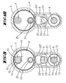
- the return spring engages the cylinder core in such a way that it assumes a dead center position in an approximately 180 ° twisted position to the neutral position, and furthermore a supplementary spring is proposed which only comes into effect in the region of the dead center position. It forces close to the dead center on the cylinder core to a complementary torque, which acts away from the dead center.
- the spring forces of the restoring spring and the supplementary spring add up in the region near the dead center position such that around the dead center position the overall spring characteristic runs steeper and only has a peak in the dead center position.
- the supplementary spring may be a bow spring which consists of a bent wire, wherein the wire is preferably bent into a ring.
- the ring may have the shape of an onion.
- the tip of the annular spring, which adjoin obliquely extending straight stirrup sections, can cooperate with a stop which is mounted in diametrical opposite position to the eccentric pin on the cylinder core.
- the spring tip of the opposite attachment portion of the supplementary spring may be attached to a wall of the chamber, which is located in the flange portion of the housing.
- a spring holder in which the attachment end is tied up with movement play.
- a fastening screw can engage in the ring clearance of the bow spring.
- the eccentric stop carries a role.
- the tip of the supplementary spring interacts with the outer shell wall of this role. Since the Roller can rotate around the stop pin, the dead center position has taken its stability.
- the return spring is not formed by a tension spring, but by a compression spring.
- the two facing away from each other ends of the compression spring in this variant also engage an eccentric pin or on a mounting pin.
- the compression spring In the neutral position, the compression spring is relaxed or slightly biased.
- the eccentric pin In this position in its farthest position to the mounting pin. If the cylinder core is rotated by 180 ° into a position in which the eccentric pin is closest to the fastening pin, the helical spring is almost completely in the chamber.
- the helical turns of the spring in the neutral position are completely in the chamber, are in the compression spring variant, the helical turns of the spring in the neutral position to the maximum rotational position completely in the chamber.
- the compression spring is supported with their ends from each coupling elements.
- the coupling elements can be formed by eyes or bearing shells.
- the coupling elements are formed by a piston and a cylinder, wherein the piston is inserted in the cylinder.
- the piston or cylinder has an eye through which one of the pins, preferably the attachment pin protrudes, which is preferably formed by a fastening screw.
- the piston preferably has a cross-shaped cross-section.
- the opening of the cylinder has a corresponding counter-profile.
- the cylinder has a bearing shell which can be clipped onto the eccentric pin.
- the length of the piston or the cylinder is dimensioned so that the piston is guided in each rotational position of the cylinder core in the cylinder.
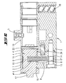
- the lock cylinders shown in the drawings are intended for installation in panic locks.
- Such panic locks have a lock housing with an insertion opening, which corresponds to the cross-sectional profile of the housing 1. This opening has a portion corresponding to the bearing portion 2 and a further portion corresponding to the flange portion 3 of the housing 1.
- Within the housing of the panic lock are a latch and a latch.
- the trap is preconnected by a latch spring and can be withdrawn by pressing a pusher.
- the bolt can be preconnected by means of the lock cylinder. This is done by rotation of the closing member 5. This occurs in a driving recess of the bolt tail. If the internal handle of the panic lock is actuated when the latch is locked, then the door pulls simultaneously with the latch retraction Latch back. This is not blocked by the closing member 5, it must be in the in the FIG. 2 shown neutral position are held.
- the drive of the closing member 5 is carried out with a rotary knob which is fixed to a connecting flange 17 on the cylinder core 4.
- the cylinder core 4 is rotatably connected via a pin 20 with a sleeve 19 of the closing member 5.
- the cylinder core 4 has two sections 4 ', 4 ", which are connected to one another via an eccentric pin 7.
- the cylinder core 4 is rotatably mounted in a bearing bore of the housing elements 14, 15 under the interposition of bushes 16.
- the housing elements 14, 15 are located on the inside of the door On the outside of the door there is likewise a cylinder core and a drill protection 18, which is formed by steel balls which engage in a radial cavity of the flange section 3.
- the housing element 14 forms a chamber 9 which is closed by the housing element 15.
- a fastening screw 8 and a retaining pin 26 hold the housing elements 14, 15 on the central housing 1.
- the fastening screw forms a fastening pin 8, which crosses the chamber 9.
- the shank of the fastening screw is smooth-walled and is partially surrounded by a bearing sleeve 10.
- the bearing sleeve 10 supports a hook end 16 of a helical gear spring 6.
- the other hook end 6 'of the tension spring 6 also engages with the interposition of a bearing sleeve 10 on the eccentric pin 7 on.
- the two bearing sleeves 10 are designed substantially the same and can be made of metal or of a plastic.
- the bearing sleeves 10 have an axial slot, so that they can be clipped onto the fastening pin 8 or the eccentric pin 7.
- the edges of the axial slot form radially projecting webs 11, 12.
- In front of the web 12 lies the free end of the hook 6 'or 6 "
- Sheath outside of the bearing sleeve 10 are located two spaced apart axial ribs 13 with a recess provided in the middle of the rib. In this recess lies the hook end 6 ', 6 ", so that the spring 6 is connected in a rotationally fixed and axially fixed manner to the bearing sleeve 19.
- the inner circumferential surface of the two bearing sleeves 10 slide on the outer walls of the eccentric pin 7 or of the fastening pin 8.
- the eccentric pin 7 has the same radial position as the closing member 5.
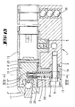
- the spring 6 forms a return spring to the closing member 5 in the in the FIGS. 2 and 3 to keep shown neutral position.
- the neutral position the helical turns of the restoring spring 6 are located substantially in the chamber 9 formed by the flange section 3. Is the cylinder core 4 in the in the FIGS. 4 and 6 rotated position shown, the return spring 6 is tensioned.
- the return spring 6 In the FIGS. 4 and 6 takes the cylinder core 4 a dead center. He is held there in an unstable equilibrium. If the cylinder core 4 slightly from this dead center, for example in the in FIG. 5 shifted position shown, the return spring 6 generates a torque on the cylinder core 4 and turns the cylinder core 4 automatically in the in the FIGS. 2 and 3 shown neutral position back.
- the supplementary spring 22 is a bow spring made of a spring steel wire bent into a ring.
- the outline contour of the ring resembles an onion shape and forms a point 22 '.
- This section is between two jaws of a spring holder 21 which is screwed with a fastening screw 23 on a wall of the chamber 9.
- the wall is formed by the closure part 15.
- the fixing screw 23 passes through the interior of the bow spring 22.
- the spring is located with lateral bending movement play in the pen holder.
- the eccentric pin 7 forms on the complementary spring 22 associated side of a ring land 27 to fix the bearing sleeve 10 axially.
- a stop pin 24 which is formed by the end of a threaded screw or a fixed force or positive locking axis, which is pressed in the axial direction in the cylinder core 4.
- the stop 24 carries a roller 25. The latter is rotatable about the stop 24.
- the roller 25 has an outer circumferential surface, which is in the area of action of the tip 22 'and the adjoining portions 22 ".
- the return spring 6 is tensioned until the eccentric pin 7 in the FIGS. 8 . 9 and 10 idealized shown Tot Vietnamese ein achieved.
- the lateral surface of the roller 25 acts on the spring section 22 "and bends the spring such that it exerts a torque on the stop 25, which is directed away from the dead center position.
- the tip 22 ' is slightly offset from the dead center line in order to reach the theoretical position as well the dead center of the eccentric pin 7 to exert a torque on the cylinder core 4.
- the adjoining the tip 22 'straight portion 22 "of the spring clip 22 engages the roller 25 at.
- the dead center effect reducing supplementary spring can be provided not only on a lock cylinder, wherein the return spring is formed by a tension spring.
- the supplementary spring arrangement is also suitable for a lock cylinder, as it is known from the aforementioned prior art ago.
- a supplementary spring which only comes into effect in the area of the dead center position can, in particular, be attached to a lock cylinder according to FIG DE 10 2004 048 231 B4 or on a lock cylinder according to DE 10 2006 020 614 be provided.
- the return spring 6 is a tension spring
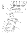
- the return spring is in the in the FIGS. 13 to 17 illustrated third embodiment, a compression spring 6.
- the lock cylinder forms a chamber 9.
- the housing element 15 is connected by means of a fastening screw 8, which forms a fastening pin, with the flange portion 3 of the lock cylinder.
- the fastening screw 8 engages through a fastening eye 29 of a piston 28.
- the piston 28 protrudes from a support surface 33 and engages in a cavity 32 of a cylinder 30 a.
- the cylinder 30 also protrudes from a support surface 34.
- the support surface 34 is formed by a bearing shell 31 which is clipped onto the eccentric pin 7.
- the helical gear compression spring 6 is located on the lateral surface of the cylinder 30.
- the end 6 'of the helical compression spring is supported on the support surface 33 of the eye 29 and the end 6 "of the return spring 6 facing away from it on the support surface 34 of the bearing shell 31.
- the length of the piston 28 and the cylinder 30 is dimensioned such that in the in FIG. 15 shown 180 ° twisted position from the neutral position of the piston 28 completely in the cylinder 30 is stuck. In the in FIG. 14 shown neutral position is only the end portion of the piston 28 in the cavity 32 of the cylinder 30th
- the piston 28 may be formed by a casting, in particular by a plastic injection-molded part and be mounted with the interposition of a bearing sleeve 10 on the mounting pin 8.
- the cylinder 30 may be made of plastic. He may also be stored with the interposition of a bearing sleeve on the eccentric pin 7.
- the bearing shell 31 surrounds the eccentric pin 7 by a peripheral region which is greater than 180 °, so that the diametral of the two arms of the bearing shell is included.
Landscapes
- Engineering & Computer Science (AREA)
- Mechanical Engineering (AREA)
- Closing And Opening Devices For Wings, And Checks For Wings (AREA)
- Gear-Shifting Mechanisms (AREA)
- Power-Operated Mechanisms For Wings (AREA)
- Lock And Its Accessories (AREA)
- Lighting Device Outwards From Vehicle And Optical Signal (AREA)
Abstract
Description
Die Erfindung betrifft zunächst einen Schließzylinder mit einem einen Lagerabschnitt und einen Flanschabschnitt aufweisenden Gehäuse, einem im Lagerabschnitt drehbar gelagerten Zylinderkern, der mit einem Schließglied drehfest verbunden ist, und mit einer Rückstellfeder, die einerseits am Gehäuse befestigt ist und andererseits an einem exzentrisch zur Drehachse des Zylinderkerns angeordneten Exzenterzapfen angreift, um den aus einer Neutralstellung verdrehten Zylinderkern wieder in die Neutralstellung zurückzudrehen.The invention relates first to a lock cylinder having a bearing portion and a flange portion having housing, a rotatably mounted in the bearing portion cylinder core, which is rotatably connected to a closing member, and with a return spring which is attached on the one hand to the housing and on the other hand at an eccentric to the axis of rotation of the Cylinder core arranged eccentric engages to turn back the twisted from a neutral position cylinder core back to the neutral position.
Ein derartiger Schließzylinder ist beispielsweise aus der
Einen ähnlichen Schließzylinder beschreibt die
Bei dem aus der
Aus der
Die
Die zuvor beschriebenen Schließzylinder bzw. der zuletzt beschriebene Zylinderadapter wird an Panikschlössern verwendet. Panikschlösser stellen die Anforderung an den Schließzylinder, dass das Schließglied des Schließzylinders immer in einer unteren neutralen Position stehen muss, da es ansonsten die Panikfunktion des Schlosses behindern könnte.The lock cylinder described above or the cylinder adapter described last is used on panic locks. Panic locks make the request to the lock cylinder that the closing member of the lock cylinder must always be in a lower neutral position, since otherwise it could hinder the panic function of the lock.
Der Erfindung liegt die Aufgabe zugrunde, einen Schließzylinder der zuvor erörterten Art schließtechnisch zu verbessern.The invention has for its object to improve a lock cylinder of the type discussed above closing technology.
Gelöst wird die Aufgabe durch die in den Ansprüchen angegebene Erfindung, wobei jeder Anspruch eine eigenständige Lösung der Aufgabe darstellt und mit jedem anderen Anspruch kombinierbar ist.The object is achieved by the invention specified in the claims, each claim represents an independent solution to the problem and can be combined with any other claim.
Zunächst und im Wesentlichen ist vorgesehen, dass die Rückstellfeder eine Druck- oder Zugfeder ist. Diese ist anders als bei der
Bei einer Weiterbildung der Erfindung greift die Rückstellfeder derart am Zylinderkern an, dass er in einer etwa 180° -Verdrehtstellung zur Neutralstellung eine Totpunktstellung einnimmt, und weiterhin wird eine Ergänzungsfeder vorgeschlagen, die erst im Bereich der Totpunktlage in Wirkung tritt. Dabei zwingt sie nahe der Totpunktlage dem Zylinderkern ein ergänzendes Drehmoment auf, welches weg von der Totpunktlage wirkt.In a further development of the invention, the return spring engages the cylinder core in such a way that it assumes a dead center position in an approximately 180 ° twisted position to the neutral position, and furthermore a supplementary spring is proposed which only comes into effect in the region of the dead center position. It forces close to the dead center on the cylinder core to a complementary torque, which acts away from the dead center.
Die Federkräfte der Rückstellfeder und der Ergänzungsfeder addieren sich im Bereich nahe der Totpunktlage derartig, dass dort um die Totpunktlage herum die Gesamtfederkennlinie steiler verläuft und lediglich in der Totpunktlage eine Spitze besitzt. Die Ergänzungsfeder kann eine Bügelfeder sein, die aus einem gebogenen Draht besteht, wobei der Draht bevorzugt zu einem Ring gebogen ist. Der Ring kann die Form einer Zwiebel aufweisen. Die Spitze der Ringfeder, der sich schräg verlaufende gerade Bügelabschnitte anschließen, kann mit einem Anschlag zusammenwirken, der in diametraler Gegenüberlage zum Exzenterzapfen am Zylinderkern befestigt ist. Der der Federspitze gegenüberliegende Befestigungsabschnitt der Ergänzungsfeder kann an einer Wandung der Kammer befestigt sein, die sich im Flanschabschnitt des Gehäuses befindet. Dort ist ein Federhalter vorgesehen, in dem das Befestigungsende mit Bewegungsspiel gefesselt ist. Eine Befestigungsschraube kann dabei in den Ringfreiraum der Bügelfeder eingreifen. In einer Weiterbildung der Erfindung ist vorgesehen, dass der exzentrische Anschlag eine Rolle trägt. Die Spitze der Ergänzungsfeder wirkt dabei mit der äußeren Mantelwand dieser Rolle zusammen. Da sich die Rolle um den Anschlagzapfen drehen kann, ist der Totpunktlage ihre Stabilität genommen.The spring forces of the restoring spring and the supplementary spring add up in the region near the dead center position such that around the dead center position the overall spring characteristic runs steeper and only has a peak in the dead center position. The supplementary spring may be a bow spring which consists of a bent wire, wherein the wire is preferably bent into a ring. The ring may have the shape of an onion. The tip of the annular spring, which adjoin obliquely extending straight stirrup sections, can cooperate with a stop which is mounted in diametrical opposite position to the eccentric pin on the cylinder core. The spring tip of the opposite attachment portion of the supplementary spring may be attached to a wall of the chamber, which is located in the flange portion of the housing. There, a spring holder is provided, in which the attachment end is tied up with movement play. A fastening screw can engage in the ring clearance of the bow spring. In one embodiment of the invention it is provided that the eccentric stop carries a role. The tip of the supplementary spring interacts with the outer shell wall of this role. Since the Roller can rotate around the stop pin, the dead center position has taken its stability.
In einer Variante der Erfindung ist vorgesehen, dass die Rückstellfeder nicht von einer Zugfeder, sondern von einer Druckfeder ausgebildet wird. Die beiden voneinander wegweisenden Enden der Druckfeder greifen bei dieser Variante ebenfalls an einem Exzenterzapfen oder an einem Befestigungszapfen an. In der Neutralstellung ist die Druckfeder entspannt bzw. geringfügig vorgespannt. Der Exzenterzapfen befindet sich in dieser Stellung in seiner entferntesten Position zum Befestigungszapfen. Wird der Zylinderkern um 180° in eine Stellung gedreht, in der der Exzenterzapfen dem Befestigungszapfen am nächsten liegt, so befindet sich die Wendelgangfeder nahezu komplett in der Kammer. Anders als bei der zuvor erörterten Variante, bei der die Wendelgänge der Feder in der Neutralstellung vollständig in der Kammer liegen, liegen bei der Druckfeder-Variante die Wendelgänge der Feder in der zur Neutralstellung maximalen Verdrehtstellung vollständig in der Kammer. Die Druckfeder stützt sich mit ihren Enden jeweils an Kupplungselementen ab. Die Kupplungselemente können von Augen oder Lagerschalen gebildet werden. Bevorzugt werden die Kupplungselemente von einem Kolben und einem Zylinder ausgebildet, wobei der Kolben im Zylinder steckt. Bevorzugt besitzt der Kolben oder der Zylinder ein Auge, durch welches einer der Zapfen, bevorzugt der Befestigungszapfen ragt, welcher bevorzugt von einer Befestigungsschraube gebildet ist. Auf der Mantelfläche des Zylinders, in welchem der Kolben eingreift, sitzt die Wendelgangdruckfeder. Der Kolben besitzt bevorzugt einen kreuzförmigen Querschnitt. Die Öffnung des Zylinders besitzt ein entsprechendes Gegenprofil. Der Zylinder besitzt eine Lagerschale, die auf den Exzenterzapfen aufgeklipst sein kann. Die Länge des Kolbens bzw. des Zylinders ist so bemessen, dass der Kolben in jeder Drehstellung des Zylinderkernes in den Zylinder geführt ist.In a variant of the invention it is provided that the return spring is not formed by a tension spring, but by a compression spring. The two facing away from each other ends of the compression spring in this variant also engage an eccentric pin or on a mounting pin. In the neutral position, the compression spring is relaxed or slightly biased. The eccentric pin is in this position in its farthest position to the mounting pin. If the cylinder core is rotated by 180 ° into a position in which the eccentric pin is closest to the fastening pin, the helical spring is almost completely in the chamber. Unlike the previously discussed variant in which the helical turns of the spring in the neutral position are completely in the chamber, are in the compression spring variant, the helical turns of the spring in the neutral position to the maximum rotational position completely in the chamber. The compression spring is supported with their ends from each coupling elements. The coupling elements can be formed by eyes or bearing shells. Preferably, the coupling elements are formed by a piston and a cylinder, wherein the piston is inserted in the cylinder. Preferably, the piston or cylinder has an eye through which one of the pins, preferably the attachment pin protrudes, which is preferably formed by a fastening screw. On the lateral surface of the cylinder, in which the piston engages, sits the helical gear spring. The piston preferably has a cross-shaped cross-section. The opening of the cylinder has a corresponding counter-profile. The cylinder has a bearing shell which can be clipped onto the eccentric pin. The length of the piston or the cylinder is dimensioned so that the piston is guided in each rotational position of the cylinder core in the cylinder.
Ausführungsbeispiele der Erfindung werden nachfolgend anhand beigefügter Zeichnungen erläutert. Es zeigen:
- Fig. 1
- in perspektivischer Darstellung das Gehäuse eines erfindungsgemä- ßen Schließzylinders,
- Fig. 2
- die Breitseitenansicht auf das Gehäuse,
- Fig. 3
- eine vergrößerte Darstellung des Schnitts III-III in der Neutralstel- lung,
- Fig. 4
- eine Darstellung gemäß
Figur 3 in einer Totpunktlage, - Fig. 5
- eine
Darstellung gemäß Figur 4 , wobei der Zylinderkern 4 geringfü- gig aus der Totpunktlage herausgedreht ist, - Fig. 6
- einen Schnitt gemäß der Linie VI-VI in
Figur 4 - Fig. 7
- eine Explosionsdarstellung der Gehäuseelemente 14,15 und deren Bestandteile,
- Fig. 8
- eine Darstellung gemäß
Figur 6 eines zweiten Ausführungsbeispiels, - Fig. 9
- einen Schnitt gemäß der Linie IX-IX in
Figur 8 - Fig. 10
- einen Schnitt der Linie X-X in
Figur 8 - Fig. 11
- eine Explosionsdarstellung der Gehäuseelemente 14, 15 und deren Bestandteile,
- Fig. 12
- eine Darstellung gemäß
Figur 10 , wobei der Zylinderkern 4 leicht aus der Totpunktlage herausgedreht ist. - Fig. 13
- eine Darstellung gemäß
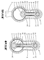
Figur 6 eines dritten Ausführungsbeispiels, bei dem die Rückstellfeder als Druckfeder ausgebildet ist, - Fig. 14
- einen Schnitt gemäß der Linie XIV-XIV in
Figur 13 - Fig. 15
- eine Darstellung gemäß
Figur 14 mit einem aus der Neutralstellung um 180° gedrehten Zylinderkern, - Fig. 16
- das Federelement des dritten Ausführungsbeispiels in einer perspek- tivischen Darstellung und
- Fig. 17
- das Federelement des dritten Ausführungsbeispiels in einer Explosi- onsdarstellung.
- Fig. 1
- 3 is a perspective view of the housing of a lock cylinder according to the invention,
- Fig. 2
- the broadside view of the case,
- Fig. 3
- an enlarged view of the section III-III in the neutral position,
- Fig. 4
- a representation according to
FIG. 3 in a dead center, - Fig. 5
- a representation according to
FIG. 4 , wherein thecylinder core 4 is slightly unscrewed from the dead center, - Fig. 6
- a section along the line VI-VI in
FIG. 4 . - Fig. 7
- an exploded view of the
housing elements - Fig. 8
- a representation according to
FIG. 6 a second embodiment, - Fig. 9
- a section along the line IX-IX in
FIG. 8 . - Fig. 10
- a section of line XX in
FIG. 8 . - Fig. 11
- an exploded view of the
housing elements - Fig. 12
- a representation according to
FIG. 10 , wherein thecylinder core 4 is slightly unscrewed from the dead center. - Fig. 13
- a representation according to
FIG. 6 a third embodiment in which the return spring is designed as a compression spring, - Fig. 14
- a section according to the line XIV-XIV in
FIG. 13 in their neutral position, - Fig. 15
- a representation according to
FIG. 14 with a cylinder core rotated by 180 ° from the neutral position, - Fig. 16
- the spring element of the third embodiment in a perspective view and
- Fig. 17
- the spring element of the third embodiment in an exploded view.
Die in den Zeichnungen dargestellten Schließzylinder sind für den Einbau in Panikschlössern vorgesehen. Derartige Panikschlösser besitzen ein Schlossgehäuse mit einer Einstecköffnung, die dem Querschnittsprofil des Gehäuses 1 entspricht. Diese Öffnung besitzt einen Abschnitt, der dem Lagerabschnitt 2 entspricht und einem weiteren Abschnitt, der dem Flanschabschnitt 3 des Gehäuses 1 entspricht. Innerhalb des Gehäuses des Panikschlosses befinden sich ein Riegel und eine Falle. Die Falle wird von einer Fallenfeder vorgeschlossen und kann durch Betätigung eines Drückers zurückgezogen werden. Der Riegel kann mittels des Schließzylinders vorgeschlossen werden. Dies erfolgt durch Drehung des Schließgliedes 5. Dieses tritt dabei in eine Mitnahmeaussparung des Riegelschwanzes. Wird bei vorgeschlossenem Riegel der Innendrücker des Panikschlosses betätigt, so fährt gleichzeitig mit dem Fallenrückzug auch der Riegel zurück. Damit dies nicht vom Schließglied 5 blockiert wird, muss es in der in der
Der Antrieb des Schließgliedes 5 erfolgt mit einem Drehknauf, der an einem Anschlussflansch 17 am Zylinderkern 4 befestigt ist. Der Zylinderkern 4 ist über einen Stift 20 mit einer Hülse 19 des Schließgliedes 5 drehfest verbunden. Der Zylinderkern 4 besitzt zwei Abschnitte 4', 4", die über einen Exzenterzapfen 7 miteinander verbunden sind. Unter der Zwischenlage von Büchsen 16 ist der Zylinderkern 4 in einer Lagerbohrung der Gehäuseelemente 14,15 drehbar gelagert. Die Gehäuseelemente 14, 15 befinden sich türinnenseitig. Türaußenseitig befindet sich ebenfalls ein Zylinderkern und ein Bohrschutz 18, der von Stahlkugeln ausgebildet ist, die in einer Radialhöhlung des Flanschabschnittes 3 einliegt.The drive of the closing
Das Gehäuseelement 14 bildet eine Kammer 9 aus, die von dem Gehäuseelement 15 verschlossen ist. Eine Befestigungsschraube 8 und ein Haltezapfen 26 halten die Gehäuseelemente 14, 15 am Zentralgehäuse 1. Die Befestigungsschraube bildet einen Befestigungszapfen 8 aus, der die Kammer 9 kreuzt. In dem die Kammer 9 kreuzenden Bereich ist der Schaft der Befestigungsschraube glattwandig gestaltet und wird teilweise von einer Lagerhülse 10 umgriffen Die Lagerhülse 10 lagert ein Hakenende 16 einer Wendelgangzugfeder 6. Das andere Hakenende 6' der Zugfeder 6 greift ebenfalls unter Zwischenlage einer Lagerhülse 10 am Exzenterzapfen 7 an.The
Die beiden Lagerhülsen 10 sind im Wesentlichen gleich gestaltet und können aus Metall oder aus einem Kunststoff bestehen. Die Lagerhülsen 10 besitzen einen Axialschlitz, so dass sie auf den Befestigungszapfen 8 bzw. den Exzenterzapfen 7 aufgeklipst werden können. Die Ränder des Axialschlitzes bilden radial abstehende Stege 11, 12. Vor dem Steg 12 liegt das freie Ende des Hakens 6' bzw. 6". Vor dem anderen Steg 11 liegt eine Windung der Feder 6. Auf der Mantelaußenseite der Lagerhülse 10 befinden sich zwei voneinander beabstandete Axialrippen 13 mit einer in Rippenmitte vorgesehenen Vertiefung. In dieser Vertiefung liegt das Hakenende 6', 6", so dass die Feder 6 drehfest und axialfest mit der Lagerhülse 19 verbunden ist. Die inneren Mantelfläche der beiden Lagerhülsen 10 gleiten auf den Außenwänden des Exzenterzapfens 7 bzw. des Befestigungszapfens 8.The two bearing
Der Exzenterzapfen 7 besitzt dieselbe Radialstellung wie das Schließglied 5. Demzufolge bildet die Feder 6 eine Rückstellfeder aus, um das Schließglied 5 in der in den
Das in den
Die Spitze 22' und die sich an die Spitze 22' anschließenden geradlinig verlaufenden Abschnitte 22' des Federdrahtes liegen im Bereich der den Zylinderkern 4 lagernden Höhlung der Gehäuseelemente 14,15. Der Exzenterzapfen 7 bildet auf der der Ergänzungsfeder 22 zugeordneten Seite einen Ringsteg 27 aus, um die Lagerhülse 10 axial zu fixieren. In diametraler Gegenüberlage zum Exzenterzapfen 7 befindet sich ein Anschlagzapfen 24, der vom Ende einer Gewindeschraube oder festsitzender Kraft-/ oder Formschlussachse ausgebildet ist, die in Achsrichtung im Zylinderkern 4 eingepresst ist. Der Anschlag 24 trägt eine Rolle 25. Letztere ist um den Anschlag 24 drehbar. Die Rolle 25 besitzt eine Außenmantelfläche, die im Wirkungsbereich der spitze 22' bzw. der sich daran anschließenden Abschnitte 22" befindet.The tip 22 'and the rectilinear portions 22' of the spring wire adjoining the tip 22 'lie in the region of the cavity of the
Wird der Zylinderkern 4 ausgehend von einer Neutralstellung gedreht, so wird die Rückstellfeder 6 gespannt, bis der Exzenterzapfen 7 die in den
Die zuletzt erörterte die Totpunktwirkung vermindernde Ergänzungsfeder kann nicht nur an einem Schließzylinder vorgesehen sein, bei dem die Rückstellfeder von einer Zugfeder ausgebildet ist. Die Ergänzungsfederanordnung eignet sich auch bei einem Schließzylinder, wie er aus dem eingangs genannten Stand der Technik her bekannt ist. Eine erst im Bereich der Totpunktstellung in Wirkung tretende Ergänzungsfeder kann insbesondere an einem Schließzylinder gemäß
Das in den
Auf der Mantelfläche des Zylinders 30 befindet sich die Wendelgangdruckfeder 6. Das Ende 6' der Wendelgangdruckfeder stützt sich auf der Stützfläche 33 des Auges 29 und das davon abgewandte Ende 6" der Rückstellfeder 6 auf der Stützfläche 34 der Lagerschale 31 ab. Die Länge des Kolbens 28 bzw. des Zylinders 30 ist dabei so bemessen, dass in der in
Bei nicht drehmomentbeaufschlagtem Schließglied 5 sorgt die Druckkraft der vorgespannten Rückstellfeder 6 dafür, dass der Zylinderkern 4 die in
Wird ausgehend von der in
Der Kolben 28 kann von einem Gussteil, insbesondere von einem Kunststoffspritzgussteil ausgebildet sein und unter Zwischenlage einer Lagerhülse 10 auf den Befestigungszapfen 8 gelagert sein. Auch der Zylinder 30 kann aus Kunststoff bestehen. Auch er kann unter Zwischenlage einer Lagerhülse am Exzenterzapfen 7 gelagert sein. Die Lagerschale 31 umgreift den Exzenterzapfen 7 um einen Umfangsbereich, der größer ist als 180°, so dass die Diametrale von den beiden Armen der Lagerschale umfasst ist.The
Es ist selbstverständlich auch möglich, dass der Zylinder das Auge und der Kolben die Lagerschale ausbildet.It is of course also possible that the cylinder forms the eye and the piston forms the bearing shell.
Claims (15)
- Lock cylinder comprising a housing (1) having a bearing portion (2) and a flange portion (3), a cylinder core (4) which is rotatably mounted in the bearing portion (2) and is rotationally engaged with a lock member (5), and comprising a restoring spring (6) which is fixed on one side to the housing (1) and, on the other side, acts on a cam pin (7), arranged off-centre from the axis of rotation of the cylinder core (4), to turn the cylinder core (4) which has been rotated out of a neutral position back into the neutral position, characterised in that a first end (6') of the restoring spring acts on a fixing pin (8) arranged in a chamber (9) of the flange portion (3) and a second end (6") acts on the cam pin (7) of the cylinder core (3).
- Lock cylinder according to claim 1, characterised in that the restoring spring (6) is a tension spring with ends in the form of hook ends, one hook end (6') encompassing the fixing pin (8) arranged in the chamber (9) of the flange portion (3) and the other hook end (6") encompassing the cam pin (7) of the cylinder core (3).
- Lock cylinder according to either of the preceding claims, characterised in that the spring (6) is a helical spring, the coils of the spring (6) lying within the chamber (9) in the neutral position or in a position of the cylinder core (4) rotated by 180° thereto.
- Lock cylinder according to any one of the preceding claims, characterised in that the cam pin (7) is the connecting web between two portions (4', 4") of the cylinder core (4).
- Lock cylinder according to any one of the preceding claims, characterised in that the hook ends (6', 6") of the spring (6) each rest on bearing sleeves (10) which are rotatably associated with the fixing pin (8) and the cam pin (7) respectively, each of the bearing sleeves (10) having in particular an axial slot in order to be placed, in particular clipped, onto the fixing pin (8) and the cam pin (7) respectively, and said bearing sleeves in particular forming radially projecting webs (11, 12) at the edges of the slot and/or forming a plurality of ribs (13) which extend substantially in the axial direction, are arranged on the surface of the bearing sleeves (10) and in each case form a central recess in which the hook end (6', 6") of the restoring spring (6) rests.
- Lock cylinder according to claim 1, characterised in that the restoring spring (6) is a compression spring, the ends (6', 6") of which are each supported on a support surface (33, 34), the support surfaces (33, 34) each being formed by an eye (29) or a bearing shell (31) which act on the cam pin (7) and the fixing pin (8) respectively, the bearing shell (31) in particular being clipped onto the cam pin (7) or the fixing pin (8).
- Lock cylinder according to any one of the preceding claims, characterised in that the bearing shell (31) or the eye (29) is formed by a piston (28) or a cylinder (30) of a piston-cylinder unit.
- Lock cylinder according to either claim 6 or claim 7, characterised in that the helical compression spring (6) is arranged on the outer surface of a cylinder (30) in which a piston (28) is located.
- Lock cylinder according to claim 8, characterised in that the piston (28) or the cavity (32) of the cylinder (30) has a cross-shaped cross-section.
- Lock cylinder according to any one of the preceding claims, characterised in that the restoring spring (6) acts on the cylinder core (4) in such a way that said core assumes a dead centre position in a position rotated by approximately 180° from the neutral position, and further characterised by a supplementary spring (22) which only becomes operative in the region of the dead centre position and applies a torque, which acts in the direction away from the dead centre position, to the cylinder core (1).
- Lock cylinder according to claim 10, characterised in that the supplementary spring (22) is a loop spring which is basically in the form of an onion in particular.
- Lock cylinder according to either claim 10 or claim 11, characterised in that the supplementary spring (22) cooperates with a stop (24) diametrically opposite the cam pin.
- Lock cylinder according to any one of claims 10 to 12, characterised in that a tip (22') of the supplementary spring (22) co-operates with the circumferential surface of a roller (25) rotatably arranged on the stop (24).
- Lock cylinder according to claim 13, characterised in that a fixing portion of the spring (22) opposite the tip (22') is fixed to the wall of a chamber (9) of the flange portion (3) with room to bend by a spring holder (21).
- Lock cylinder according to any one of claims 10 to 14, characterised by a fixing screw (23) which penetrates through the interior of the loop of the spring (22).
Applications Claiming Priority (2)
| Application Number | Priority Date | Filing Date | Title |
|---|---|---|---|
| DE102008005179 | 2008-01-19 | ||
| DE102008029686.4A DE102008029686B4 (en) | 2008-01-19 | 2008-06-23 | Lock cylinder with automatic return of the closing member |
Publications (2)
| Publication Number | Publication Date |
|---|---|
| EP2088263A1 EP2088263A1 (en) | 2009-08-12 |
| EP2088263B1 true EP2088263B1 (en) | 2010-06-23 |
Family
ID=40785995
Family Applications (1)
| Application Number | Title | Priority Date | Filing Date |
|---|---|---|---|
| EP09150499A Active EP2088263B1 (en) | 2008-01-19 | 2009-01-14 | Lock cylinder with with automatic return of the lock cam |
Country Status (4)
| Country | Link |
|---|---|
| EP (1) | EP2088263B1 (en) |
| AT (1) | ATE472025T1 (en) |
| DE (3) | DE102008029686B4 (en) |
| ES (1) | ES2345421T3 (en) |
Cited By (1)
| Publication number | Priority date | Publication date | Assignee | Title |
|---|---|---|---|---|
| EP2568101A2 (en) | 2011-09-12 | 2013-03-13 | Assa Abloy Sicherheitstechnik GmbH | Knob cylinder |
Families Citing this family (6)
| Publication number | Priority date | Publication date | Assignee | Title |
|---|---|---|---|---|
| EP2597229B1 (en) | 2011-11-25 | 2015-04-22 | CEStronics GmbH | Coupling section, bolt device, reset mechanism, cylinder housing, cylinder device, closing cylinder and plug-in lock as well as a reset and assembly method |
| DE102012108432B4 (en) | 2012-06-13 | 2019-05-09 | Uhlmann & Zacher Gmbh | Anti panic cylinder |
| DE102012108998B3 (en) * | 2012-09-24 | 2014-05-22 | Uhlmann & Zacher Gmbh | Lock cylinder i.e. anti-panic cylinder, for use in box lock for closing door in emergency exit of building, has sill flap arranged at housing, and magnet connected with housing for exerting torque on flap and arranged in recess of housing |
| EP2738325B1 (en) * | 2012-11-30 | 2017-06-14 | SimonsVoss Technologies GmbH | Anti-panic cylinder |
| DE102013001501C5 (en) * | 2013-01-29 | 2017-03-16 | Klaus Meister | Reset system for the locking lug of electronic locking systems |
| FR3080894B1 (en) * | 2018-05-04 | 2021-11-26 | Latecoere | PROCESS AND SYSTEM FOR MAINTAINING A SHAFT IN BISTABLE POSITIONING |
Family Cites Families (7)
| Publication number | Priority date | Publication date | Assignee | Title |
|---|---|---|---|---|
| DE1553510A1 (en) * | 1965-01-15 | 1969-08-21 | Witte & Co Ewald | Cylinder lock for actuation, in particular of motor vehicle locks |
| FR2510647A1 (en) * | 1981-07-30 | 1983-02-04 | Neiman Sa | Lever or cam bolt for lock - has direct fit to cylinder barrel on axial extension with engaging flats |
| JP3298737B2 (en) * | 1994-04-28 | 2002-07-08 | 株式会社アルファ | Key cylinder automatic return device for cylinder lock device |
| DE10243615B4 (en) * | 2002-09-19 | 2004-09-23 | Meister, Klaus, Dr. | Electronic cylinder system for panic locks |
| DE10316522B3 (en) * | 2003-04-10 | 2004-07-08 | Seccor High Security Gmbh | Automatic resetting system for electronic locking system used with panic lock for access door has eccentric core supported by spring-loaded ball bearing defining rest position of locking cam axis |
| DE102004048231B4 (en) * | 2004-10-04 | 2006-08-03 | Simonsvoss Technologies Ag | Resetting device for use in anti-panic lock, has spring arrangement that is arranged in longitudinal direction of locking cylinder and producing turning movement, which moves attachment of cylinder into predetermined position |
| DE102006020614B4 (en) * | 2005-04-29 | 2017-02-02 | Mehmet Sancak | Lock with automatic reset of the lock |
-
2008
- 2008-06-23 DE DE102008029686.4A patent/DE102008029686B4/en not_active Expired - Fee Related
-
2009
- 2009-01-14 ES ES09150499T patent/ES2345421T3/en active Active
- 2009-01-14 DE DE202009017880U patent/DE202009017880U1/en not_active Expired - Lifetime
- 2009-01-14 DE DE502009000032T patent/DE502009000032D1/en active Active
- 2009-01-14 EP EP09150499A patent/EP2088263B1/en active Active
- 2009-01-14 AT AT09150499T patent/ATE472025T1/en active
Cited By (2)
| Publication number | Priority date | Publication date | Assignee | Title |
|---|---|---|---|---|
| EP2568101A2 (en) | 2011-09-12 | 2013-03-13 | Assa Abloy Sicherheitstechnik GmbH | Knob cylinder |
| DE102011113796A1 (en) | 2011-09-12 | 2013-03-14 | Assa Abloy Sicherheitstechnik Gmbh | Knaufzylinder |
Also Published As
| Publication number | Publication date |
|---|---|
| DE102008029686A1 (en) | 2009-07-23 |
| EP2088263A1 (en) | 2009-08-12 |
| ATE472025T1 (en) | 2010-07-15 |
| ES2345421T3 (en) | 2010-09-22 |
| DE102008029686B4 (en) | 2016-07-28 |
| DE502009000032D1 (en) | 2010-08-05 |
| DE202009017880U1 (en) | 2010-08-12 |
Similar Documents
| Publication | Publication Date | Title |
|---|---|---|
| EP2088263B1 (en) | Lock cylinder with with automatic return of the lock cam | |
| DE102011102159B4 (en) | Modular lock cylinder | |
| DE102015112859B3 (en) | Door handle and drive carrier | |
| EP3153648B1 (en) | Padlock | |
| DE102009023561A1 (en) | padlock | |
| EP2951373A1 (en) | Furniture fitting | |
| DE102012003168A1 (en) | lock cylinders | |
| EP2410110B1 (en) | Locking cylinder, in particular double locking cylinder with free-running locking element | |
| DE102010017388A1 (en) | Device for coupling and decoupling an exterior door handle | |
| DE102012100424B4 (en) | Device for controlling the closing sequence of double-leaf swing doors | |
| EP2302272B1 (en) | Valve cartridge | |
| DE19859714C1 (en) | Lock cylinder with flat key | |
| DE102008034070A1 (en) | Lock cylinder i.e. double lock cylinder, has tilting lever tilted and/or shifted if eccentric pin passes dead center position of lever during rotation of cylinder core, where center position is opposite to neutral position | |
| EP2299041A2 (en) | Dampening device for mobile pieces of furniture | |
| DE202006016305U1 (en) | Handle for a door or window is formed as a hollow body containing a locking unit with a handle element for actuating the locking unit | |
| DE10041652B4 (en) | Distance-adjustable striker for rotary latch locks | |
| DE10329414B4 (en) | closing device | |
| DE102019113666A1 (en) | Lock cylinder | |
| DE19822030A1 (en) | Two part hollow shaft for door handles | |
| EP1887151B1 (en) | Articulation fitting | |
| EP0606877B1 (en) | Door fitting for a lock with a latchbalt and a deadbolt | |
| EP3741933B1 (en) | Locking device | |
| EP3636863B1 (en) | Securing device for a joint | |
| EP2317164B1 (en) | Hook, in particular for safety devices | |
| EP2199548A1 (en) | Device for resetting a phase adjuster for a cam shaft |
Legal Events
| Date | Code | Title | Description |
|---|---|---|---|
| PUAI | Public reference made under article 153(3) epc to a published international application that has entered the european phase |
Free format text: ORIGINAL CODE: 0009012 |
|
| AK | Designated contracting states |
Kind code of ref document: A1 Designated state(s): AT BE BG CH CY CZ DE DK EE ES FI FR GB GR HR HU IE IS IT LI LT LU LV MC MK MT NL NO PL PT RO SE SI SK TR |
|
| AX | Request for extension of the european patent |
Extension state: AL BA RS |
|
| RTI1 | Title (correction) |
Free format text: LOCK CYLINDER WITH WITH AUTOMATIC RETURN OF THE LOCK CAM |
|
| 17P | Request for examination filed |
Effective date: 20091125 |
|
| RIC1 | Information provided on ipc code assigned before grant |
Ipc: E05B 15/04 20060101ALI20100119BHEP Ipc: E05B 9/04 20060101AFI20100119BHEP |
|
| GRAP | Despatch of communication of intention to grant a patent |
Free format text: ORIGINAL CODE: EPIDOSNIGR1 |
|
| GRAS | Grant fee paid |
Free format text: ORIGINAL CODE: EPIDOSNIGR3 |
|
| AKX | Designation fees paid |
Designated state(s): AT BE BG CH CY CZ DE DK EE ES FI FR GB GR HR HU IE IS IT LI LT LU LV MC MK MT NL NO PL PT RO SE SI SK TR |
|
| GRAA | (expected) grant |
Free format text: ORIGINAL CODE: 0009210 |
|
| AK | Designated contracting states |
Kind code of ref document: B1 Designated state(s): AT BE BG CH CY CZ DE DK EE ES FI FR GB GR HR HU IE IS IT LI LT LU LV MC MK MT NL NO PL PT RO SE SI SK TR |
|
| REG | Reference to a national code |
Ref country code: CH Ref legal event code: EP |
|
| REG | Reference to a national code |
Ref country code: IE Ref legal event code: FG4D Free format text: LANGUAGE OF EP DOCUMENT: GERMAN |
|
| REG | Reference to a national code |
Ref country code: NL Ref legal event code: T3 |
|
| REF | Corresponds to: |
Ref document number: 502009000032 Country of ref document: DE Date of ref document: 20100805 Kind code of ref document: P |
|
| REG | Reference to a national code |
Ref country code: CH Ref legal event code: NV Representative=s name: R. A. EGLI & CO. PATENTANWAELTE |
|
| REG | Reference to a national code |
Ref country code: ES Ref legal event code: FG2A Ref document number: 2345421 Country of ref document: ES Kind code of ref document: T3 |
|
| PG25 | Lapsed in a contracting state [announced via postgrant information from national office to epo] |
Ref country code: SE Free format text: LAPSE BECAUSE OF FAILURE TO SUBMIT A TRANSLATION OF THE DESCRIPTION OR TO PAY THE FEE WITHIN THE PRESCRIBED TIME-LIMIT Effective date: 20100623 Ref country code: LT Free format text: LAPSE BECAUSE OF FAILURE TO SUBMIT A TRANSLATION OF THE DESCRIPTION OR TO PAY THE FEE WITHIN THE PRESCRIBED TIME-LIMIT Effective date: 20100623 Ref country code: NO Free format text: LAPSE BECAUSE OF FAILURE TO SUBMIT A TRANSLATION OF THE DESCRIPTION OR TO PAY THE FEE WITHIN THE PRESCRIBED TIME-LIMIT Effective date: 20100923 |
|
| LTIE | Lt: invalidation of european patent or patent extension |
Effective date: 20100623 |
|
| PG25 | Lapsed in a contracting state [announced via postgrant information from national office to epo] |
Ref country code: FI Free format text: LAPSE BECAUSE OF FAILURE TO SUBMIT A TRANSLATION OF THE DESCRIPTION OR TO PAY THE FEE WITHIN THE PRESCRIBED TIME-LIMIT Effective date: 20100623 Ref country code: HR Free format text: LAPSE BECAUSE OF FAILURE TO SUBMIT A TRANSLATION OF THE DESCRIPTION OR TO PAY THE FEE WITHIN THE PRESCRIBED TIME-LIMIT Effective date: 20100623 Ref country code: LV Free format text: LAPSE BECAUSE OF FAILURE TO SUBMIT A TRANSLATION OF THE DESCRIPTION OR TO PAY THE FEE WITHIN THE PRESCRIBED TIME-LIMIT Effective date: 20100623 Ref country code: SI Free format text: LAPSE BECAUSE OF FAILURE TO SUBMIT A TRANSLATION OF THE DESCRIPTION OR TO PAY THE FEE WITHIN THE PRESCRIBED TIME-LIMIT Effective date: 20100623 |
|
| PG25 | Lapsed in a contracting state [announced via postgrant information from national office to epo] |
Ref country code: PL Free format text: LAPSE BECAUSE OF FAILURE TO SUBMIT A TRANSLATION OF THE DESCRIPTION OR TO PAY THE FEE WITHIN THE PRESCRIBED TIME-LIMIT Effective date: 20100623 |
|
| PG25 | Lapsed in a contracting state [announced via postgrant information from national office to epo] |
Ref country code: EE Free format text: LAPSE BECAUSE OF FAILURE TO SUBMIT A TRANSLATION OF THE DESCRIPTION OR TO PAY THE FEE WITHIN THE PRESCRIBED TIME-LIMIT Effective date: 20100623 |
|
| REG | Reference to a national code |
Ref country code: IE Ref legal event code: FD4D |
|
| PG25 | Lapsed in a contracting state [announced via postgrant information from national office to epo] |
Ref country code: SK Free format text: LAPSE BECAUSE OF FAILURE TO SUBMIT A TRANSLATION OF THE DESCRIPTION OR TO PAY THE FEE WITHIN THE PRESCRIBED TIME-LIMIT Effective date: 20100623 Ref country code: IS Free format text: LAPSE BECAUSE OF FAILURE TO SUBMIT A TRANSLATION OF THE DESCRIPTION OR TO PAY THE FEE WITHIN THE PRESCRIBED TIME-LIMIT Effective date: 20101023 Ref country code: CZ Free format text: LAPSE BECAUSE OF FAILURE TO SUBMIT A TRANSLATION OF THE DESCRIPTION OR TO PAY THE FEE WITHIN THE PRESCRIBED TIME-LIMIT Effective date: 20100623 Ref country code: CY Free format text: LAPSE BECAUSE OF FAILURE TO SUBMIT A TRANSLATION OF THE DESCRIPTION OR TO PAY THE FEE WITHIN THE PRESCRIBED TIME-LIMIT Effective date: 20100623 Ref country code: RO Free format text: LAPSE BECAUSE OF FAILURE TO SUBMIT A TRANSLATION OF THE DESCRIPTION OR TO PAY THE FEE WITHIN THE PRESCRIBED TIME-LIMIT Effective date: 20100623 |
|
| PG25 | Lapsed in a contracting state [announced via postgrant information from national office to epo] |
Ref country code: DK Free format text: LAPSE BECAUSE OF FAILURE TO SUBMIT A TRANSLATION OF THE DESCRIPTION OR TO PAY THE FEE WITHIN THE PRESCRIBED TIME-LIMIT Effective date: 20100623 Ref country code: IE Free format text: LAPSE BECAUSE OF FAILURE TO SUBMIT A TRANSLATION OF THE DESCRIPTION OR TO PAY THE FEE WITHIN THE PRESCRIBED TIME-LIMIT Effective date: 20100623 |
|
| PLBE | No opposition filed within time limit |
Free format text: ORIGINAL CODE: 0009261 |
|
| STAA | Information on the status of an ep patent application or granted ep patent |
Free format text: STATUS: NO OPPOSITION FILED WITHIN TIME LIMIT |
|
| PG25 | Lapsed in a contracting state [announced via postgrant information from national office to epo] |
Ref country code: GR Free format text: LAPSE BECAUSE OF FAILURE TO SUBMIT A TRANSLATION OF THE DESCRIPTION OR TO PAY THE FEE WITHIN THE PRESCRIBED TIME-LIMIT Effective date: 20100924 |
|
| 26N | No opposition filed |
Effective date: 20110324 |
|
| REG | Reference to a national code |
Ref country code: DE Ref legal event code: R097 Ref document number: 502009000032 Country of ref document: DE Effective date: 20110323 |
|
| PG25 | Lapsed in a contracting state [announced via postgrant information from national office to epo] |
Ref country code: MC Free format text: LAPSE BECAUSE OF NON-PAYMENT OF DUE FEES Effective date: 20110131 |
|
| PG25 | Lapsed in a contracting state [announced via postgrant information from national office to epo] |
Ref country code: MT Free format text: LAPSE BECAUSE OF FAILURE TO SUBMIT A TRANSLATION OF THE DESCRIPTION OR TO PAY THE FEE WITHIN THE PRESCRIBED TIME-LIMIT Effective date: 20100623 |
|
| PGFP | Annual fee paid to national office [announced via postgrant information from national office to epo] |
Ref country code: TR Payment date: 20120109 Year of fee payment: 4 |
|
| PG25 | Lapsed in a contracting state [announced via postgrant information from national office to epo] |
Ref country code: LU Free format text: LAPSE BECAUSE OF NON-PAYMENT OF DUE FEES Effective date: 20110114 |
|
| PG25 | Lapsed in a contracting state [announced via postgrant information from national office to epo] |
Ref country code: PT Free format text: LAPSE BECAUSE OF NON-PAYMENT OF DUE FEES Effective date: 20100623 |
|
| PG25 | Lapsed in a contracting state [announced via postgrant information from national office to epo] |
Ref country code: BG Free format text: LAPSE BECAUSE OF FAILURE TO SUBMIT A TRANSLATION OF THE DESCRIPTION OR TO PAY THE FEE WITHIN THE PRESCRIBED TIME-LIMIT Effective date: 20100923 |
|
| PG25 | Lapsed in a contracting state [announced via postgrant information from national office to epo] |
Ref country code: HU Free format text: LAPSE BECAUSE OF FAILURE TO SUBMIT A TRANSLATION OF THE DESCRIPTION OR TO PAY THE FEE WITHIN THE PRESCRIBED TIME-LIMIT Effective date: 20100623 |
|
| REG | Reference to a national code |
Ref country code: DE Ref legal event code: R082 Ref document number: 502009000032 Country of ref document: DE Representative=s name: WITTE, WELLER & PARTNER PATENTANWAELTE MBB, DE |
|
| REG | Reference to a national code |
Ref country code: FR Ref legal event code: PLFP Year of fee payment: 8 |
|
| REG | Reference to a national code |
Ref country code: FR Ref legal event code: PLFP Year of fee payment: 9 |
|
| PG25 | Lapsed in a contracting state [announced via postgrant information from national office to epo] |
Ref country code: TR Free format text: LAPSE BECAUSE OF NON-PAYMENT OF DUE FEES Effective date: 20140114 |
|
| REG | Reference to a national code |
Ref country code: FR Ref legal event code: PLFP Year of fee payment: 10 |
|
| PGFP | Annual fee paid to national office [announced via postgrant information from national office to epo] |
Ref country code: FR Payment date: 20230123 Year of fee payment: 15 |
|
| PGFP | Annual fee paid to national office [announced via postgrant information from national office to epo] |
Ref country code: IT Payment date: 20230131 Year of fee payment: 15 Ref country code: BE Payment date: 20230123 Year of fee payment: 15 |
|
| PGFP | Annual fee paid to national office [announced via postgrant information from national office to epo] |
Ref country code: NL Payment date: 20240123 Year of fee payment: 16 |
|
| PGFP | Annual fee paid to national office [announced via postgrant information from national office to epo] |
Ref country code: ES Payment date: 20240216 Year of fee payment: 16 |
|
| PGFP | Annual fee paid to national office [announced via postgrant information from national office to epo] |
Ref country code: AT Payment date: 20240118 Year of fee payment: 16 |
|
| PGFP | Annual fee paid to national office [announced via postgrant information from national office to epo] |
Ref country code: DE Payment date: 20240325 Year of fee payment: 16 Ref country code: CH Payment date: 20240202 Year of fee payment: 16 Ref country code: GB Payment date: 20240124 Year of fee payment: 16 |