EP2568101A2 - Knob cylinder - Google Patents
Knob cylinder Download PDFInfo
- Publication number
- EP2568101A2 EP2568101A2 EP20120075104 EP12075104A EP2568101A2 EP 2568101 A2 EP2568101 A2 EP 2568101A2 EP 20120075104 EP20120075104 EP 20120075104 EP 12075104 A EP12075104 A EP 12075104A EP 2568101 A2 EP2568101 A2 EP 2568101A2
- Authority
- EP
- European Patent Office
- Prior art keywords
- knob
- magnetic
- knob shaft
- shaft
- cylinder
- Prior art date
- Legal status (The legal status is an assumption and is not a legal conclusion. Google has not performed a legal analysis and makes no representation as to the accuracy of the status listed.)
- Granted
Links
- 230000005415 magnetization Effects 0.000 claims description 4
- 230000007935 neutral effect Effects 0.000 description 6
- 230000000694 effects Effects 0.000 description 2
- 230000004323 axial length Effects 0.000 description 1
- 238000009434 installation Methods 0.000 description 1
- 230000000284 resting effect Effects 0.000 description 1
Images

Classifications
-
- E—FIXED CONSTRUCTIONS
- E05—LOCKS; KEYS; WINDOW OR DOOR FITTINGS; SAFES
- E05B—LOCKS; ACCESSORIES THEREFOR; HANDCUFFS
- E05B15/00—Other details of locks; Parts for engagement by bolts of fastening devices
- E05B15/0053—Other details of locks; Parts for engagement by bolts of fastening devices means providing a stable, i.e. indexed, position of lock parts
- E05B15/0073—Other details of locks; Parts for engagement by bolts of fastening devices means providing a stable, i.e. indexed, position of lock parts magnetically operated
-
- E—FIXED CONSTRUCTIONS
- E05—LOCKS; KEYS; WINDOW OR DOOR FITTINGS; SAFES
- E05B—LOCKS; ACCESSORIES THEREFOR; HANDCUFFS
- E05B47/00—Operating or controlling locks or other fastening devices by electric or magnetic means
- E05B47/06—Controlling mechanically-operated bolts by electro-magnetically-operated detents
- E05B47/0611—Cylinder locks with electromagnetic control
- E05B47/0615—Cylinder locks with electromagnetic control operated by handles, e.g. by knobs
-
- E—FIXED CONSTRUCTIONS
- E05—LOCKS; KEYS; WINDOW OR DOOR FITTINGS; SAFES
- E05B—LOCKS; ACCESSORIES THEREFOR; HANDCUFFS
- E05B9/00—Lock casings or latch-mechanism casings ; Fastening locks or fasteners or parts thereof to the wing
- E05B9/04—Casings of cylinder locks
- E05B2009/047—Means for returning cylinder locks to their neutral position
Definitions
- the invention relates to a knob cylinder, the knob shaft or spindle is rotatably connected to the cam of a lock cylinder.
- the key can only be removed in a defined position of the key.
- knob cylinder usually have no fixed position in the rotation of the knob, which corresponds to this basic or neutral position.
- Knob cylinders can be operated from the outside either with the key or an electronic knob.
- lock cylinders which are not to be opened from the outside with a key but via an electronic knob and from the inside with a mechanical knob, there is usually no fixed cam position.
- the z. B. panic doors, escape route doors or fire doors is required.
- These lock cylinders require that the actuator of the lock cylinder after a completed closing operation, always in its normal position or neutral position in the range of 3:00 to 9:00 o'clock, for example, to exercise the panic function.
- the invention is therefore based on the object to provide a knob cylinder, in which the cam is brought forcibly after a closing operation in a position between 3:00 clock and 9:00 clock, and if possible without a dead center in the return movement, so that thus the conditions for installation in z.
- a knob cylinder in which the cam is brought forcibly after a closing operation in a position between 3:00 clock and 9:00 clock, and if possible without a dead center in the return movement, so that thus the conditions for installation in z.
- the cam is brought forcibly after a closing operation in a position between 3:00 clock and 9:00 clock
- the restoring device occupies the smallest possible space, in particular, that it can be installed in existing lock cylinder without much effort, for example subsequently.
- knob shaft or spindle is rotatably connected to the cam of a lock cylinder, wherein for the provision of the cam in a basic position, a rotating on the knob shaft acting magnet arrangement is provided.
- magnetic discs are arranged, which are alternately oriented in opposite directions and each consist of two or more segments, each one of the magnetic discs against the knob shaft receiving lock cylinder housing is held against rotation and the associated axially closest magnetic disc is held against rotation with respect to the knob shaft and the magnetic poles are selected such that the magnetic disc connected to the knob shaft is constantly rotated back into the basic position.
- a "fixed" magnetic disk (consisting of two or more segments) is located between two (or more) equal / unevenly polarized magnetic disks.
- the housing-fixed magnetic disk keeps its position, for example, via a small "nose", which engages in a housing groove.
- the two other magnetic disks, between which the magnetic disk fixed to the housing, are firmly connected to the knob shaft.
- the magnetic poles are now chosen so that the middle magnetic disk is attracted in the "resting state" of the two outer magnetic disks. If the knob shaft is now twisted, then the cylinder-fixed magnet segments come in the repulsively polarized area of the outer magnet segments and are rotated back by it. At a middle magnetic disk. which comes into effect with two adjacent magnetic disks, no external magnetic forces occur because the outer magnetic disks center to the middle magnetic disk.
- the knob shaft coaxially surrounding at least two mutually oppositely oriented magnetic rings are provided, wherein the inner magnetic ring against rotation of the knob shaft and the outer magnetic ring against rotation of the lock cylinder housing is held and the magnetic poles are chosen so that with the knob shaft connected magnetic ring is constantly rotated back to the normal position.
- Magnetic disks are therefore not used here, ie magnets in which the axial extent due to the disk-like design is small, but magnetic rings which have a comparatively larger axial length (or width).
- these magnetic rings are arranged coaxially, ie lie inside each other.
- the magnetized areas may be either diametrical in this solution, ie seen in the circumferential direction, the polarity alternates, or they may be radially aligned.
- the inner circumference of the magnetic ring has a different polarity than the outer circumference, wherein, of course, in the associated, coaxially arranged magnetic ring, the polarity, for example, on the outer circumference opposite to the inner circumference of the other magnetic ring.
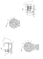
- FIG. 1 schematically shows a knob cylinder, in which on one side of the only partially shown, with an electronic knob cylinder or with a key to be operated lock cylinder 3 is located. On the opposite side a knob 1 is indicated.
- the lock cylinder housing is designated 2. That the knob shaft 7 ( FIGS. 2a and b ) connected to the cylinder core of the lock cylinder, the cam 5 receiving the closing member is denoted by 4.
- the cut AA in FIG. 2a shows one of the magnetic disks 6 with the different polarities. This magnetic disk 6 encloses the knob shaft 7, wherein this is rotatably arranged in the magnetic disk. However, this magnetic disk 7 itself is held by a nose 8, which engages in a recess 9 in the lock cylinder housing 2 against this rotationally.
- the cut BB in FIG. 2b indicates the axially adjacent magnetic disk 10 again, wherein it can be seen that this is rotationally connected to the knob shaft 7.
- the magnetic disk 10 rotates with this and relative to the locked by the lock cylinder housing magnetic disk 6. Due to the opposite polarities acts so that the magnetic force resettable to the knob shaft, so that these in a basic position or neutral position, as shown in the FIG. 2a is shown, is turned back.
- the magnetic disks can also be divided into several segments.
- FIG. 3 shows the axial juxtaposition of the magnetic disks 6 and 10, wherein in this embodiment, a magnetic disk 6 on both sides of the magnetic disks 10 are assigned.
- Denoted at 11 are the axial position of the magnetic disk defining means.
- the magnetic disks which have only a small axial extent or width, replaced by magnetic rings.
- the magnetic rings are now, for example - as in the FIG. 4 represented - coaxially arranged one inside the other.
- the coaxial inner magnet ring 14 is located on the knob shaft or is connected to this rotationally fixed.
- the magnetization is diametrical in these magnetic rings, similar to the previously described magnetic disks.
- the variant is constructive FIG. 5 constructed the same way, with the difference that here the magnetization is radial, that is different on the respective inner circumference than on the outer circumference of the magnetic ring.
Landscapes
- Physics & Mathematics (AREA)
- Electromagnetism (AREA)
- Lock And Its Accessories (AREA)
- Mechanical Control Devices (AREA)
- Adjustable Resistors (AREA)
- Preventing Unauthorised Actuation Of Valves (AREA)
Abstract
Description
Die Erfindung betrifft einen Knaufzylinder, dessen Knaufwelle oder -spindel drehfest mit dem Schließbart eines Schließzylinders verbunden ist.The invention relates to a knob cylinder, the knob shaft or spindle is rotatably connected to the cam of a lock cylinder.
Bei Schließzylinder, die ausschließlich mit einem Schlüssel betätigt werden, kann der Schlüssel nur in einer definierten Stellung des Schlüssels abgezogen werden.For lock cylinders, which are operated only with a key, the key can only be removed in a defined position of the key.
Demgegenüber haben Knaufzylinder meist keine feste Position bei der Verdrehung des Knaufes, die dieser Grund- oder Neutralstellung entspricht.
Knaufzylinder können von der Außenseite entweder mit dem Schlüssel oder einem elektronischen Knauf betätigt werden.In contrast, knob cylinder usually have no fixed position in the rotation of the knob, which corresponds to this basic or neutral position.
Knob cylinders can be operated from the outside either with the key or an electronic knob.
Insbesondere bei Schließzylindern, die von außen nicht mit einem Schlüssel sondern über einen Elektronikknauf und von Innen mit einem mechanischen Knauf zu öffnen sind, gibt es meist keine feste Schließbartposition. die z. B. bei Paniktüren, Fluchtwegtüren oder auch Feuerschutztüren erforderlich ist.
Bei diesen Schließzylindern besteht die Forderung, dass das Stellglied des Schließzylinders nach einem ausgeführten Schließvorgang, immer in seiner Grundstellung oder Neutralstellung im Bereich von 3:00 bis 9:00Uhr stehen muss, um beispielsweise die Panikfunktion ausüben zu können.Especially with lock cylinders, which are not to be opened from the outside with a key but via an electronic knob and from the inside with a mechanical knob, there is usually no fixed cam position. the z. B. panic doors, escape route doors or fire doors is required.
These lock cylinders require that the actuator of the lock cylinder after a completed closing operation, always in its normal position or neutral position in the range of 3:00 to 9:00 o'clock, for example, to exercise the panic function.
Aus der
Eine andere, ebenfalls auf die Wirkung einer Feder aufbauende Rückstelleinrichtung ist aus der
Nachteilig bei den bisher bekannten Lösungen ist, dass ein nicht unerheblicher Bauraum konstruktiv bedingt eingenommen wird bzw. notwendig ist, um die Rückstellfedern unterzubringen. Dies bedeutet,dass die konstruktiven Elemente sowohl in der Knaufwelle wie auch im Zylindergehäuse angeordnet sind.A disadvantage of the previously known solutions is that a considerable space is taken constructively due or is necessary to accommodate the return springs. This means that the structural elements are arranged both in the knob shaft and in the cylinder housing.
Ein weiterer Nachteil besteht darin, dass sich Totpunkte bei Rückstellfedern nicht vermeiden lassen, d. h. es gibt bestimmte Stellungen des Stellgliedes und damit des Schließbartes, bei denen die Rückstellfeder an einer Rückdrehung in die Grund- oder Neutralstellung gehindert ist.
Damit kann unter Umständen die Panikfunktion nicht ausgeübt werden, zumindest nicht sicher genug.Another disadvantage is that dead points in return springs can not be avoided, ie there are certain positions of the actuator and thus the cam, in which the return spring is prevented from turning back into the basic or neutral position.
Thus, under certain circumstances, the panic function can not be exercised, at least not sure enough.
Der Erfindung liegt daher die Aufgabe zugrunde, einen Knaufzylinder bereitzustellen, bei dem der Schließbart zwangsmäßig nach einem Schließvorgang in eine Position zwischen 3:00 Uhr und 9:00 Uhr gebracht wird, und zwar möglichst ohne das bei der Rückstellbewegung ein Totpunkt vorhanden ist, so dass damit die Voraussetzungen für den Einbau in z. B. Brandschutztüren, Paniktüren oder Fluchtwegtüren gegeben sind.The invention is therefore based on the object to provide a knob cylinder, in which the cam is brought forcibly after a closing operation in a position between 3:00 clock and 9:00 clock, and if possible without a dead center in the return movement, so that thus the conditions for installation in z. As fire doors, panic doors or escape route doors are given.
Ein weiterer, wesentlicher Punkt ist, dass die Rückstelleinrichtung einen möglichst geringen Bauraum einnimmt, insbesondere, dass sie auch in bestehende Schließzylinder ohne großen Aufwand, beispielsweise nachträglich, einbaubar ist.Another essential point is that the restoring device occupies the smallest possible space, in particular, that it can be installed in existing lock cylinder without much effort, for example subsequently.
Gelöst wird diese Aufgabe erfindungsgemäß mit einem Knaufzylinder, dessen Knaufwelle oder -spindel drehfest mit dem Schließbart eines Schließzylinder verbunden ist,
wobei zur Rückstellung des Schließbartes in eine Grundstellung, eine auf die Knaufwelle drehend wirkende Magnetanordnung vorgesehen ist.This object is achieved according to the invention with a knob cylinder, the knob shaft or spindle is rotatably connected to the cam of a lock cylinder,
wherein for the provision of the cam in a basic position, a rotating on the knob shaft acting magnet arrangement is provided.
Gemäß einer vorzugsweisen Ausführung ist vorgesehen, dass auf der Knaufwelle axial hintereinander mehrere die Knaufwelle umgebende Magnetscheiben angeordnet sind, die abwechselnd gegenpolig ausgerichtet sind und jeweils aus zwei oder mehr Segmenten bestehen, wobei jeweils eine der Magnetscheiben gegenüber dem die Knaufwelle aufnehmenden Schließzylindergehäuse verdrehfest gehalten ist und die zugeordnete axial nächstliegende Magnetscheibe gegenüber der Knaufwelle drehfest gehalten ist und die Magnetpolungen so gewählt sind, dass die mit der Knaufwelle verbundene Magnetscheibe ständig in die Grundstellung zurückgedreht wird.According to a preferred embodiment, it is provided that on the knob shaft axially successively surrounding the knob shaft magnetic discs are arranged, which are alternately oriented in opposite directions and each consist of two or more segments, each one of the magnetic discs against the knob shaft receiving lock cylinder housing is held against rotation and the associated axially closest magnetic disc is held against rotation with respect to the knob shaft and the magnetic poles are selected such that the magnetic disc connected to the knob shaft is constantly rotated back into the basic position.
Diese Lösung zeichnet sich insbesondere dadurch aus, dass das Rückstellsystem keinen Totpunkt aufweist.This solution is characterized in particular by the fact that the reset system has no dead center.
Die Lösung besteht darin, dass eine "gehäusefeste" Magnetscheibe (bestehend aus zwei oder mehreren Segmenten) sich zwischen zwei (oder mehreren) gleich / ungleich gepolten Magnetscheiben befindet. Die gehäusefeste Magnetscheibe hält ihre Lage beispielsweise über eine kleine "Nase", die in eine Gehäusenut eingreift. Die beiden anderen Magnetscheiben, zwischen denen sich die gehäusefeste Magnetscheibe befindet, sind fest mit der Knaufwelle verbunden. Die Magnetpolungen sind nun so gewählt, dass die mittlere Magnetscheibe im "Ruhezustand" von den beiden äußeren Magnetscheiben angezogen wird. Wird die Knaufwelle nun verdreht, dann kommen die zylinderfesten Magnetsegmente in den abstoßend gepolten Bereich der äußeren Magnetsegmente und werden davon zurückgedreht.
Bei einer mittleren Magnetscheibe. die mit zwei benachbarten Magnetscheiben in Wirkung tritt, treten keine äußeren Magnetkräfte auf, da sich die äußeren Magnetscheiben zur mittleren Magnetscheibe zentrieren.The solution is that a "fixed" magnetic disk (consisting of two or more segments) is located between two (or more) equal / unevenly polarized magnetic disks. The housing-fixed magnetic disk keeps its position, for example, via a small "nose", which engages in a housing groove. The two other magnetic disks, between which the magnetic disk fixed to the housing, are firmly connected to the knob shaft. The magnetic poles are now chosen so that the middle magnetic disk is attracted in the "resting state" of the two outer magnetic disks. If the knob shaft is now twisted, then the cylinder-fixed magnet segments come in the repulsively polarized area of the outer magnet segments and are rotated back by it.
At a middle magnetic disk. which comes into effect with two adjacent magnetic disks, no external magnetic forces occur because the outer magnetic disks center to the middle magnetic disk.
Bei einer Anordnung mit jeweils nur einer gehäusefesten und einer drehbaren Magnetscheibe treten dagegen axiale Kräfte auf. Die zurückdrehend wirkende Funktion der beiden Magnetscheiben ist aber gegeben.In an arrangement with only one housing-fixed and a rotatable magnetic disk, however, occur on axial forces. The retro-rotating effect of the two magnetic disks is given.
Bei dieser Lösung kommen - wie beschrieben - Magnetscheiben zum Einsatz.In this solution - as described - magnetic disks are used.
Nach einer anderen Ausführungsform der Erfindung ist vorgesehen, dass die Knaufwelle koaxial umgebend mindestens zwei gegenpolig ausgerichtete Magnetringe vorgesehen sind, wobei der innere Magnetring verdrehfest gegenüber der Knaufwelle und der äußere Magnetring verdrehfest gegenüber dem Schließzylindergehäuse gehalten ist und die Magnetpolungen so gewählt sind, dass der mit der Knaufwelle verbundene Magnetring ständig in die Grundstellung zurückgedreht wird.According to another embodiment of the invention, it is provided that the knob shaft coaxially surrounding at least two mutually oppositely oriented magnetic rings are provided, wherein the inner magnetic ring against rotation of the knob shaft and the outer magnetic ring against rotation of the lock cylinder housing is held and the magnetic poles are chosen so that with the knob shaft connected magnetic ring is constantly rotated back to the normal position.
Hierbei kommen somit nicht Magnetscheiben zu Einsatz, also Magnete, bei denen die axiale Erstreckung aufgrund der scheibenartigen Ausbildung , gering ist, sondern Magnetringe, die eine vergleichsweise größere axiale Länge (oder Breite) aufweisen.Magnetic disks are therefore not used here, ie magnets in which the axial extent due to the disk-like design is small, but magnetic rings which have a comparatively larger axial length (or width).
Darüber hinaus sind diese Magnetringe koaxial angeordnet, d. h. liegen ineinander.In addition, these magnetic rings are arranged coaxially, ie lie inside each other.
Die magnetisierten Bereiche können bei dieser Lösung entweder diametral sein, d.h. in Umfangsrichtung gesehen wechselt sich die Polarität ab, oder sie können radial ausgerichtet sein.
Bei dieser radialen Ausrichtung weist der Innenumfang des Magnetringes eine andere Polarität auf als der Außenumfang, wobei natürlich bei dem zugehörigen , koaxial angeordneten Magnetring, die Polarität beispielsweise am Außenumfang entgegengesetzt der des Innenumfangs des anderen Magnetringes ist.
Die Erfindung soll nachfolgend mit Bezug auf die Zeichnungen erläutert werden.The magnetized areas may be either diametrical in this solution, ie seen in the circumferential direction, the polarity alternates, or they may be radially aligned.
In this radial orientation, the inner circumference of the magnetic ring has a different polarity than the outer circumference, wherein, of course, in the associated, coaxially arranged magnetic ring, the polarity, for example, on the outer circumference opposite to the inner circumference of the other magnetic ring.
The invention will be explained below with reference to the drawings.
Dabei zeigt:
- Fig. 1
- eine schematische Darstellung der Knaufseite eines Knaufzylinders,
- Fig. 2a und b
- Schnitte gemäß A-A und B-B in
Figur 1 für die erste Ausführungsform, - Fig. 3
- ein Detail aus
Figur 1 und - Fig.4 und 5
- die zweite Ausführungsform in zwei Varianten.
- Fig. 1
- a schematic representation of the knob side of a knob cylinder,
- Fig. 2a and b
- Cuts according to AA and BB in
FIG. 1 for the first embodiment, - Fig. 3
- a detail from
FIG. 1 and - 4 and 5
- the second embodiment in two variants.
Die
Das die Knaufwelle 7 (
Der Schnitt A-A in
Der Schnitt B-B in
That the knob shaft 7 (
The cut AA in
The cut BB in
Wird die Knaufwelle 7 verdreht, so dreht sich die Magnetscheibe 10 mit dieser und relativ zu der vom Schließzylindergehäuse arretierten Magnetscheibe 6. Aufgrund der entgegengesetzten Polaritäten wirkt damit die Magnetkraft rückstellend auf die Knaufwelle ein, so dass diese in eine Grundstellung oder Neutralstellung, wie sie in der
Selbstverständlich können die Magnetscheiben auch in mehrere Segmente unterteilt sein.Of course, the magnetic disks can also be divided into several segments.
Die Detaildarstellung in
Mit 11 sind die axiale Position der Magnetscheiben festlegende Mittel bezeichnet.The detailed representation in
Denoted at 11 are the axial position of the magnetic disk defining means.
Bei der zweiten Ausführungsart, wie sie in den
Darüber hinaus sind die Magnetringe nun beispielsweise - wie in der
Beim äußeren Magnetring 12 ist die Nase 13 erkennbar, d. h. dieser Magnetring ist gegenüber dem hier nicht dargestellten Schließzylindergehäuse verdrehfest gehalten.When
Der koaxial innere Magnetring 14 befindet sich auf der Knaufwelle bzw. wird mit dieser verdrehfest verbunden.The coaxial
Die Magnetisierung ist bei diesen Magnetringen, ähnlich wie bei den vorher beschriebenen Magnetscheiben, diametral.The magnetization is diametrical in these magnetic rings, similar to the previously described magnetic disks.
Konstruktiv ist die Variante nach
Claims (6)
dadurch gekennzeichnet,
dass zur Rückstellung des Schließbartes (5) in eine Grundstellung, eine auf die Knaufwelle (7) drehend wirkende Magnetanordnung (6,10;12,14) vorgesehen ist.Knob cylinder, the knob shaft (7) or spindle rotatably connected to the cam (5) of a lock cylinder,
characterized,
in that provision is made for restoring the locking bit (5) into a basic position, a magnet arrangement (6, 10, 12, 14) which acts in a rotating manner on the knob shaft (7).
dadurch gekennzeichnet,
dass auf der Knaufwelle (7) axial hintereinander mehrere die Knaufwelle umgebende Magnetscheiben (6,10) angeordnet sind, die abwechselnd gegenpolig ausgerichtet sind und jeweils aus zwei oder mehr Segmenten bestehen, wobei jeweils eine der Magnetscheiben (6) gegenüber dem die Knaufwelle aufnehmenden Schließzylindergehäuse (2) verdrehfest gehalten ist und mindestens eine zugeordnete axial nächstliegende Magnetscheiben (10) gegenüber der Knaufwelle (7) drehfest gehalten ist und die Magnetpolungen so gewählt sind, dass die mit der Knaufwelle (7) verbundene Magnetscheibe (10) ständig in die Grundstellung zurückgedreht wird.Knob cylinder according to claim 1,
characterized,
that on the knob shaft (7) axially in succession a plurality of the knob shaft surrounding magnetic discs (6,10) are arranged, which are alternately aligned opposite polarity and each consist of two or more segments, each one of the magnetic discs (6) relative to the knob shaft receiving lock cylinder housing (2) is held rotationally fixed and at least one associated axially closest magnetic discs (10) relative to the knob shaft (7) is held against rotation and the magnetic polings are chosen so that the knob shaft (7) connected to the magnetic disc (10) constantly rotated back to the normal position becomes.
dadurch gekennzeichnet,
dass die Knaufwelle (7) koaxial umgebend mindestens zwei gegenpolig ausgerichtete Magnetringe (12,14) vorgesehen sind, wobei der innere Magnetring verdrehfest (14) gegenüber der Knaufwelle (7) und der äußere Magnetring (12) verdrehfest gegenüber dem Schließzylindergehäuse (2) gehalten ist und die Magnetpolungen so gewählt sind, dass der mit der Knaufwelle verbundene Magnetring (14) ständig in die Grundstellung zurückgedreht wird.Knob cylinder according to claim 1,
characterized,
in that the knob shaft (7) is provided coaxially surrounding at least two magnetic rings (12, 14) aligned opposite each other, wherein the inner magnet ring is held against rotation with respect to the knob shaft (7) and the outer magnet ring (12) is rotationally fixed relative to the lock cylinder housing (2) is and the magnetic poles are chosen so that the connected to the knob shaft magnetic ring (14) is constantly rotated back to the normal position.
dadurch gekennzeichnet,
dass die Magnetringe eine diametrale Magnetisierung aufweisen.Knob cylinder according to claim 3,
characterized,
that the magnetic rings have a diametrical magnetization.
dadurch gekennzeichnet,
dass die Magnetringe eine radiale Magnetisierung aufweisen.Knob cylinder according to claim 3,
characterized,
that the magnetic rings have a radial magnetization.
dadurch gekennzeichnet,
dass die Magnetanordnung nur den Bauraum der Knaufwelle einnimmt.Knob cylinder according to one of the preceding claims,
characterized,
that the magnet arrangement occupies only the space of the knob shaft.
Applications Claiming Priority (1)
| Application Number | Priority Date | Filing Date | Title |
|---|---|---|---|
| DE102011113796A DE102011113796A1 (en) | 2011-09-12 | 2011-09-12 | Knaufzylinder |
Publications (3)
| Publication Number | Publication Date |
|---|---|
| EP2568101A2 true EP2568101A2 (en) | 2013-03-13 |
| EP2568101A3 EP2568101A3 (en) | 2014-04-30 |
| EP2568101B1 EP2568101B1 (en) | 2015-11-18 |
Family
ID=46939462
Family Applications (1)
| Application Number | Title | Priority Date | Filing Date |
|---|---|---|---|
| EP12075104.5A Active EP2568101B1 (en) | 2011-09-12 | 2012-09-10 | Knob cylinder |
Country Status (2)
| Country | Link |
|---|---|
| EP (1) | EP2568101B1 (en) |
| DE (1) | DE102011113796A1 (en) |
Cited By (1)
| Publication number | Priority date | Publication date | Assignee | Title |
|---|---|---|---|---|
| WO2018226835A2 (en) | 2017-06-06 | 2018-12-13 | Schlage Lock Company Llc | Lever return mechanism using magnets |
Families Citing this family (3)
| Publication number | Priority date | Publication date | Assignee | Title |
|---|---|---|---|---|
| DE102012108998B3 (en) * | 2012-09-24 | 2014-05-22 | Uhlmann & Zacher Gmbh | Lock cylinder i.e. anti-panic cylinder, for use in box lock for closing door in emergency exit of building, has sill flap arranged at housing, and magnet connected with housing for exerting torque on flap and arranged in recess of housing |
| DE102014111413B3 (en) | 2014-08-11 | 2015-09-17 | ASTRA Gesellschaft für Asset Management mbH & Co. KG | Lock cylinder arrangement |
| US20230349195A1 (en) * | 2022-04-29 | 2023-11-02 | Iloq Oy | Electromechanical lock cylinder |
Citations (2)
| Publication number | Priority date | Publication date | Assignee | Title |
|---|---|---|---|---|
| EP2088263B1 (en) | 2008-01-19 | 2010-06-23 | DOM-Sicherheitstechnik GmbH & Co. KG | Lock cylinder with with automatic return of the lock cam |
| EP2115246B1 (en) | 2007-02-08 | 2010-10-06 | EVVA Sicherheitstechnologie GmbH | Lock having self-activated lock bit resetting |
Family Cites Families (7)
| Publication number | Priority date | Publication date | Assignee | Title |
|---|---|---|---|---|
| CH492107A (en) * | 1966-11-19 | 1970-06-15 | Huwil Werke Gmbh | Lock with magnetic tumblers |
| DE19923786A1 (en) * | 1998-06-03 | 1999-12-09 | Dom Sicherheitstechnik | Improved closure cylinder achieving operational connection from outside to closure section |
| DE20023646U1 (en) * | 2000-09-08 | 2005-07-07 | Meis, Guido | Keyless locking device for door has control unit activated by switching arrangement by operating manual control switch that interacts with lock cylinder integrated into cylinder/housing |
| DE10238153A1 (en) * | 2002-08-15 | 2004-03-25 | Wittenstein Ag | Locking device for vehicles, in particular for aircraft |
| DE10303220B3 (en) * | 2003-01-23 | 2004-09-16 | Dom Sicherheitstechnik Gmbh & Co Kg | lock cylinder |
| DE102009043358A1 (en) * | 2008-04-11 | 2011-04-07 | Cestronics Gmbh | Lock cylinder with magnetically coupled closing element |
| AT509465B1 (en) * | 2010-03-30 | 2011-09-15 | Evva Sicherheitstechnologie | APPARATUS FOR ACCESS CONTROL WITH ELECTROMECHANICAL CONVERTER |
-
2011
- 2011-09-12 DE DE102011113796A patent/DE102011113796A1/en not_active Withdrawn
-
2012
- 2012-09-10 EP EP12075104.5A patent/EP2568101B1/en active Active
Patent Citations (2)
| Publication number | Priority date | Publication date | Assignee | Title |
|---|---|---|---|---|
| EP2115246B1 (en) | 2007-02-08 | 2010-10-06 | EVVA Sicherheitstechnologie GmbH | Lock having self-activated lock bit resetting |
| EP2088263B1 (en) | 2008-01-19 | 2010-06-23 | DOM-Sicherheitstechnik GmbH & Co. KG | Lock cylinder with with automatic return of the lock cam |
Cited By (3)
| Publication number | Priority date | Publication date | Assignee | Title |
|---|---|---|---|---|
| WO2018226835A2 (en) | 2017-06-06 | 2018-12-13 | Schlage Lock Company Llc | Lever return mechanism using magnets |
| EP3635203A4 (en) * | 2017-06-06 | 2021-04-28 | Schlage Lock Company LLC | Lever return mechanism using magnets |
| US11732500B2 (en) | 2017-06-06 | 2023-08-22 | Schlage Lock Company Llc | Lever return mechanism using magnets |
Also Published As
| Publication number | Publication date |
|---|---|
| EP2568101B1 (en) | 2015-11-18 |
| DE102011113796A1 (en) | 2013-03-14 |
| EP2568101A3 (en) | 2014-04-30 |
Similar Documents
| Publication | Publication Date | Title |
|---|---|---|
| DE2711061C2 (en) | Permanent magnet key operated lock | |
| EP1987218B1 (en) | Lock with safety system | |
| EP2568101B1 (en) | Knob cylinder | |
| DE102011015314A1 (en) | lock cylinder | |
| EP2162816B1 (en) | Rotating actuator with a variable latching profile | |
| DE102006059599A1 (en) | Locking cylinder with tumbler pin displaceable by magnetic force and associated key | |
| DE2905941A1 (en) | CONTROL DEVICE, IN PARTICULAR LOCK | |
| DE102009029826B4 (en) | Solenoid valve | |
| EP0053095B1 (en) | Emergency key device in a double cylinder lock | |
| EP2360343B1 (en) | Sliding window or sliding door with a closing device | |
| AT520252B1 (en) | Coupling system for an electromechanical lock | |
| EP2931995B1 (en) | Lock cylinder and reversible key with key-withdrawal device | |
| EP2985398B1 (en) | Lock-cylinder assembly | |
| DE2853185A1 (en) | CYLINDER LOCK WITH MAGNETIC BODIES | |
| DE2330014A1 (en) | Cylinder lock with magnetic key - actuated by pressing or turning key adjustable magnetic lock | |
| EP0835975B1 (en) | Cylinder lock | |
| DE102011106896A1 (en) | Coupling system for single/double-sided key-operated lock cylinder, has pressure element that is arranged between coupling portions is pressed along axial direction of cylinder core | |
| DE102010021250A1 (en) | Valve, particularly solenoid valve, comprises valve housing, in which valve member is arranged axially movable, and two permanent magnet arrangements for holding valve member by magnetic force | |
| EP1731696A2 (en) | Lock cylinder for electronic locking system | |
| DE2746896A1 (en) | Electrically controlled turnstile barrier - has revolving spindle, anchor and electromagnetic coupling for one or two way setting | |
| AT367148B (en) | CYLINDER LOCK WITH A HOUSING AND AT LEAST ONE ROTATING CYLINDER CORE | |
| DE2365990C3 (en) | Rotary cylinder lock that can be operated by means of a permanent magnet key | |
| DE248416C (en) | ||
| DE1553365C (en) | By means of a key equipped with magnets actuatable rotary cylinder closed | |
| DE20213365U1 (en) | throttling device |
Legal Events
| Date | Code | Title | Description |
|---|---|---|---|
| PUAI | Public reference made under article 153(3) epc to a published international application that has entered the european phase |
Free format text: ORIGINAL CODE: 0009012 |
|
| AK | Designated contracting states |
Kind code of ref document: A2 Designated state(s): AL AT BE BG CH CY CZ DE DK EE ES FI FR GB GR HR HU IE IS IT LI LT LU LV MC MK MT NL NO PL PT RO RS SE SI SK SM TR |
|
| AX | Request for extension of the european patent |
Extension state: BA ME |
|
| PUAL | Search report despatched |
Free format text: ORIGINAL CODE: 0009013 |
|
| AK | Designated contracting states |
Kind code of ref document: A3 Designated state(s): AL AT BE BG CH CY CZ DE DK EE ES FI FR GB GR HR HU IE IS IT LI LT LU LV MC MK MT NL NO PL PT RO RS SE SI SK SM TR |
|
| AX | Request for extension of the european patent |
Extension state: BA ME |
|
| RIC1 | Information provided on ipc code assigned before grant |
Ipc: E05B 47/00 20060101AFI20140321BHEP Ipc: E05B 9/04 20060101ALI20140321BHEP |
|
| 17P | Request for examination filed |
Effective date: 20141014 |
|
| RBV | Designated contracting states (corrected) |
Designated state(s): AL AT BE BG CH CY CZ DE DK EE ES FI FR GB GR HR HU IE IS IT LI LT LU LV MC MK MT NL NO PL PT RO RS SE SI SK SM TR |
|
| 17Q | First examination report despatched |
Effective date: 20150113 |
|
| GRAP | Despatch of communication of intention to grant a patent |
Free format text: ORIGINAL CODE: EPIDOSNIGR1 |
|
| INTG | Intention to grant announced |
Effective date: 20150616 |
|
| GRAS | Grant fee paid |
Free format text: ORIGINAL CODE: EPIDOSNIGR3 |
|
| GRAA | (expected) grant |
Free format text: ORIGINAL CODE: 0009210 |
|
| AK | Designated contracting states |
Kind code of ref document: B1 Designated state(s): AL AT BE BG CH CY CZ DE DK EE ES FI FR GB GR HR HU IE IS IT LI LT LU LV MC MK MT NL NO PL PT RO RS SE SI SK SM TR |
|
| REG | Reference to a national code |
Ref country code: GB Ref legal event code: FG4D Free format text: NOT ENGLISH |
|
| REG | Reference to a national code |
Ref country code: CH Ref legal event code: EP Ref country code: CH Ref legal event code: NV Representative=s name: E. BLUM AND CO. AG PATENT- UND MARKENANWAELTE , CH |
|
| REG | Reference to a national code |
Ref country code: AT Ref legal event code: REF Ref document number: 761667 Country of ref document: AT Kind code of ref document: T Effective date: 20151215 |
|
| REG | Reference to a national code |
Ref country code: IE Ref legal event code: FG4D Free format text: LANGUAGE OF EP DOCUMENT: GERMAN |
|
| REG | Reference to a national code |
Ref country code: DE Ref legal event code: R096 Ref document number: 502012005217 Country of ref document: DE |
|
| REG | Reference to a national code |
Ref country code: NL Ref legal event code: FP |
|
| REG | Reference to a national code |
Ref country code: LT Ref legal event code: MG4D |
|
| PG25 | Lapsed in a contracting state [announced via postgrant information from national office to epo] |
Ref country code: NO Free format text: LAPSE BECAUSE OF FAILURE TO SUBMIT A TRANSLATION OF THE DESCRIPTION OR TO PAY THE FEE WITHIN THE PRESCRIBED TIME-LIMIT Effective date: 20160218 Ref country code: HR Free format text: LAPSE BECAUSE OF FAILURE TO SUBMIT A TRANSLATION OF THE DESCRIPTION OR TO PAY THE FEE WITHIN THE PRESCRIBED TIME-LIMIT Effective date: 20151118 Ref country code: ES Free format text: LAPSE BECAUSE OF FAILURE TO SUBMIT A TRANSLATION OF THE DESCRIPTION OR TO PAY THE FEE WITHIN THE PRESCRIBED TIME-LIMIT Effective date: 20151118 Ref country code: IT Free format text: LAPSE BECAUSE OF FAILURE TO SUBMIT A TRANSLATION OF THE DESCRIPTION OR TO PAY THE FEE WITHIN THE PRESCRIBED TIME-LIMIT Effective date: 20151118 Ref country code: LT Free format text: LAPSE BECAUSE OF FAILURE TO SUBMIT A TRANSLATION OF THE DESCRIPTION OR TO PAY THE FEE WITHIN THE PRESCRIBED TIME-LIMIT Effective date: 20151118 Ref country code: IS Free format text: LAPSE BECAUSE OF FAILURE TO SUBMIT A TRANSLATION OF THE DESCRIPTION OR TO PAY THE FEE WITHIN THE PRESCRIBED TIME-LIMIT Effective date: 20160318 |
|
| PG25 | Lapsed in a contracting state [announced via postgrant information from national office to epo] |
Ref country code: PL Free format text: LAPSE BECAUSE OF FAILURE TO SUBMIT A TRANSLATION OF THE DESCRIPTION OR TO PAY THE FEE WITHIN THE PRESCRIBED TIME-LIMIT Effective date: 20151118 Ref country code: PT Free format text: LAPSE BECAUSE OF FAILURE TO SUBMIT A TRANSLATION OF THE DESCRIPTION OR TO PAY THE FEE WITHIN THE PRESCRIBED TIME-LIMIT Effective date: 20160318 Ref country code: SE Free format text: LAPSE BECAUSE OF FAILURE TO SUBMIT A TRANSLATION OF THE DESCRIPTION OR TO PAY THE FEE WITHIN THE PRESCRIBED TIME-LIMIT Effective date: 20151118 Ref country code: GR Free format text: LAPSE BECAUSE OF FAILURE TO SUBMIT A TRANSLATION OF THE DESCRIPTION OR TO PAY THE FEE WITHIN THE PRESCRIBED TIME-LIMIT Effective date: 20160219 Ref country code: RS Free format text: LAPSE BECAUSE OF FAILURE TO SUBMIT A TRANSLATION OF THE DESCRIPTION OR TO PAY THE FEE WITHIN THE PRESCRIBED TIME-LIMIT Effective date: 20151118 Ref country code: LV Free format text: LAPSE BECAUSE OF FAILURE TO SUBMIT A TRANSLATION OF THE DESCRIPTION OR TO PAY THE FEE WITHIN THE PRESCRIBED TIME-LIMIT Effective date: 20151118 Ref country code: FI Free format text: LAPSE BECAUSE OF FAILURE TO SUBMIT A TRANSLATION OF THE DESCRIPTION OR TO PAY THE FEE WITHIN THE PRESCRIBED TIME-LIMIT Effective date: 20151118 |
|
| PG25 | Lapsed in a contracting state [announced via postgrant information from national office to epo] |
Ref country code: CZ Free format text: LAPSE BECAUSE OF FAILURE TO SUBMIT A TRANSLATION OF THE DESCRIPTION OR TO PAY THE FEE WITHIN THE PRESCRIBED TIME-LIMIT Effective date: 20151118 |
|
| REG | Reference to a national code |
Ref country code: FR Ref legal event code: PLFP Year of fee payment: 5 |
|
| REG | Reference to a national code |
Ref country code: DE Ref legal event code: R097 Ref document number: 502012005217 Country of ref document: DE |
|
| PG25 | Lapsed in a contracting state [announced via postgrant information from national office to epo] |
Ref country code: DK Free format text: LAPSE BECAUSE OF FAILURE TO SUBMIT A TRANSLATION OF THE DESCRIPTION OR TO PAY THE FEE WITHIN THE PRESCRIBED TIME-LIMIT Effective date: 20151118 Ref country code: SK Free format text: LAPSE BECAUSE OF FAILURE TO SUBMIT A TRANSLATION OF THE DESCRIPTION OR TO PAY THE FEE WITHIN THE PRESCRIBED TIME-LIMIT Effective date: 20151118 Ref country code: EE Free format text: LAPSE BECAUSE OF FAILURE TO SUBMIT A TRANSLATION OF THE DESCRIPTION OR TO PAY THE FEE WITHIN THE PRESCRIBED TIME-LIMIT Effective date: 20151118 Ref country code: SM Free format text: LAPSE BECAUSE OF FAILURE TO SUBMIT A TRANSLATION OF THE DESCRIPTION OR TO PAY THE FEE WITHIN THE PRESCRIBED TIME-LIMIT Effective date: 20151118 Ref country code: RO Free format text: LAPSE BECAUSE OF FAILURE TO SUBMIT A TRANSLATION OF THE DESCRIPTION OR TO PAY THE FEE WITHIN THE PRESCRIBED TIME-LIMIT Effective date: 20151118 |
|
| PLBE | No opposition filed within time limit |
Free format text: ORIGINAL CODE: 0009261 |
|
| STAA | Information on the status of an ep patent application or granted ep patent |
Free format text: STATUS: NO OPPOSITION FILED WITHIN TIME LIMIT |
|
| 26N | No opposition filed |
Effective date: 20160819 |
|
| PG25 | Lapsed in a contracting state [announced via postgrant information from national office to epo] |
Ref country code: SI Free format text: LAPSE BECAUSE OF FAILURE TO SUBMIT A TRANSLATION OF THE DESCRIPTION OR TO PAY THE FEE WITHIN THE PRESCRIBED TIME-LIMIT Effective date: 20151118 |
|
| PG25 | Lapsed in a contracting state [announced via postgrant information from national office to epo] |
Ref country code: MC Free format text: LAPSE BECAUSE OF FAILURE TO SUBMIT A TRANSLATION OF THE DESCRIPTION OR TO PAY THE FEE WITHIN THE PRESCRIBED TIME-LIMIT Effective date: 20151118 |
|
| REG | Reference to a national code |
Ref country code: IE Ref legal event code: MM4A |
|
| PG25 | Lapsed in a contracting state [announced via postgrant information from national office to epo] |
Ref country code: IE Free format text: LAPSE BECAUSE OF NON-PAYMENT OF DUE FEES Effective date: 20160910 |
|
| REG | Reference to a national code |
Ref country code: FR Ref legal event code: PLFP Year of fee payment: 6 |
|
| PG25 | Lapsed in a contracting state [announced via postgrant information from national office to epo] |
Ref country code: LU Free format text: LAPSE BECAUSE OF NON-PAYMENT OF DUE FEES Effective date: 20160910 |
|
| PG25 | Lapsed in a contracting state [announced via postgrant information from national office to epo] |
Ref country code: HU Free format text: LAPSE BECAUSE OF FAILURE TO SUBMIT A TRANSLATION OF THE DESCRIPTION OR TO PAY THE FEE WITHIN THE PRESCRIBED TIME-LIMIT; INVALID AB INITIO Effective date: 20120910 Ref country code: CY Free format text: LAPSE BECAUSE OF FAILURE TO SUBMIT A TRANSLATION OF THE DESCRIPTION OR TO PAY THE FEE WITHIN THE PRESCRIBED TIME-LIMIT Effective date: 20151118 |
|
| PG25 | Lapsed in a contracting state [announced via postgrant information from national office to epo] |
Ref country code: MK Free format text: LAPSE BECAUSE OF FAILURE TO SUBMIT A TRANSLATION OF THE DESCRIPTION OR TO PAY THE FEE WITHIN THE PRESCRIBED TIME-LIMIT Effective date: 20151118 Ref country code: TR Free format text: LAPSE BECAUSE OF FAILURE TO SUBMIT A TRANSLATION OF THE DESCRIPTION OR TO PAY THE FEE WITHIN THE PRESCRIBED TIME-LIMIT Effective date: 20151118 Ref country code: MT Free format text: LAPSE BECAUSE OF FAILURE TO SUBMIT A TRANSLATION OF THE DESCRIPTION OR TO PAY THE FEE WITHIN THE PRESCRIBED TIME-LIMIT Effective date: 20151118 |
|
| PG25 | Lapsed in a contracting state [announced via postgrant information from national office to epo] |
Ref country code: BG Free format text: LAPSE BECAUSE OF FAILURE TO SUBMIT A TRANSLATION OF THE DESCRIPTION OR TO PAY THE FEE WITHIN THE PRESCRIBED TIME-LIMIT Effective date: 20151118 |
|
| REG | Reference to a national code |
Ref country code: FR Ref legal event code: PLFP Year of fee payment: 7 |
|
| PG25 | Lapsed in a contracting state [announced via postgrant information from national office to epo] |
Ref country code: AL Free format text: LAPSE BECAUSE OF FAILURE TO SUBMIT A TRANSLATION OF THE DESCRIPTION OR TO PAY THE FEE WITHIN THE PRESCRIBED TIME-LIMIT Effective date: 20151118 |
|
| PGFP | Annual fee paid to national office [announced via postgrant information from national office to epo] |
Ref country code: NL Payment date: 20230816 Year of fee payment: 12 |
|
| PGFP | Annual fee paid to national office [announced via postgrant information from national office to epo] |
Ref country code: GB Payment date: 20230810 Year of fee payment: 12 Ref country code: AT Payment date: 20230825 Year of fee payment: 12 |
|
| PGFP | Annual fee paid to national office [announced via postgrant information from national office to epo] |
Ref country code: FR Payment date: 20230821 Year of fee payment: 12 Ref country code: DE Payment date: 20230808 Year of fee payment: 12 Ref country code: BE Payment date: 20230818 Year of fee payment: 12 |
|
| PGFP | Annual fee paid to national office [announced via postgrant information from national office to epo] |
Ref country code: CH Payment date: 20231001 Year of fee payment: 12 |