EP1987218B1 - Lock with safety system - Google Patents
Lock with safety system Download PDFInfo
- Publication number
- EP1987218B1 EP1987218B1 EP20070701317 EP07701317A EP1987218B1 EP 1987218 B1 EP1987218 B1 EP 1987218B1 EP 20070701317 EP20070701317 EP 20070701317 EP 07701317 A EP07701317 A EP 07701317A EP 1987218 B1 EP1987218 B1 EP 1987218B1
- Authority
- EP
- European Patent Office
- Prior art keywords
- lock
- knob
- flyweight
- shaft
- locking
- Prior art date
- Legal status (The legal status is an assumption and is not a legal conclusion. Google has not performed a legal analysis and makes no representation as to the accuracy of the status listed.)
- Not-in-force
Links
Images

Classifications
-
- E—FIXED CONSTRUCTIONS
- E05—LOCKS; KEYS; WINDOW OR DOOR FITTINGS; SAFES
- E05B—LOCKS; ACCESSORIES THEREFOR; HANDCUFFS
- E05B13/00—Devices preventing the key or the handle or both from being used
-
- E—FIXED CONSTRUCTIONS
- E05—LOCKS; KEYS; WINDOW OR DOOR FITTINGS; SAFES
- E05B—LOCKS; ACCESSORIES THEREFOR; HANDCUFFS
- E05B47/00—Operating or controlling locks or other fastening devices by electric or magnetic means
- E05B47/06—Controlling mechanically-operated bolts by electro-magnetically-operated detents
- E05B47/0611—Cylinder locks with electromagnetic control
- E05B47/0615—Cylinder locks with electromagnetic control operated by handles, e.g. by knobs
-
- E—FIXED CONSTRUCTIONS
- E05—LOCKS; KEYS; WINDOW OR DOOR FITTINGS; SAFES
- E05B—LOCKS; ACCESSORIES THEREFOR; HANDCUFFS
- E05B47/00—Operating or controlling locks or other fastening devices by electric or magnetic means
- E05B47/06—Controlling mechanically-operated bolts by electro-magnetically-operated detents
- E05B47/0676—Controlling mechanically-operated bolts by electro-magnetically-operated detents by disconnecting the handle
-
- Y—GENERAL TAGGING OF NEW TECHNOLOGICAL DEVELOPMENTS; GENERAL TAGGING OF CROSS-SECTIONAL TECHNOLOGIES SPANNING OVER SEVERAL SECTIONS OF THE IPC; TECHNICAL SUBJECTS COVERED BY FORMER USPC CROSS-REFERENCE ART COLLECTIONS [XRACs] AND DIGESTS
- Y10—TECHNICAL SUBJECTS COVERED BY FORMER USPC
- Y10T—TECHNICAL SUBJECTS COVERED BY FORMER US CLASSIFICATION
- Y10T70/00—Locks
- Y10T70/50—Special application
- Y10T70/5611—For control and machine elements
- Y10T70/5757—Handle, handwheel or knob
- Y10T70/5765—Rotary or swinging
- Y10T70/5805—Freely movable when locked
Definitions
- the invention relates to a lock with a safety device and a handle part or knob which is freely rotatable in the idle state and in the opening or closing state with the locking member of the lock, wherein the or the centrifugal weight (s) from a first detent position radially be displaced outwards into a second latching position.
- Such a lock with a safety device is from the CA 2,097,992 known.
- Conventional locks can be operated by means of a key, by turning a key in a lock a corresponding locking lug is rotated, which moves a bolt in a closed position or retracts from a closed position to an open position.
- Electronic security systems use a recognition logic and an electronic key in the form of cards, key fobs or other identification media instead of the key. After reading the key, which corresponds to the mechanical scanning of a conventional key, the rotational movement of a knob or handle via a corresponding coupling with another rotatably mounted part rotatably coupled, which operates in the sequence the bolt.
- electronic security systems which are designed as a double-knob cylinder, wherein on one side of the door to be opened elements of a detection logic, and in particular antennas or the like., Are arranged, whereas the coupling of the rotational movement of this outer rotatable part after detecting the correct key via an electronics usually made by electrical means by coupling a coupling element.
- the external knob or handle is freely rotatable without such a coupling.
- This freely rotatable knob or handle is connected via a shaft to the opposite side of the door or window, at which the coupling is made with the actuator of the lock.
- the invention now aims to exclude such sabotage or incorrect operation with certainty and to ensure that the freely rotatable handle part or the freely rotatable knob remains freely rotatable only with a relatively low rotational speed and counteracts rubbing or jamming in other cases.
- the solution according to the invention is that the flyweight or the flyweight (s) are displaced radially outwardly from a first detent position into a second detent position, whereby a precise function is ensured.
- the design is such that the handle part or knob is connected to a dipping into the housing of the lock shaft having at least one radial opening in which a centrifugal weight is arranged with a lying outside the axis of rotation center of gravity and that in the housing of the lock, a recess or groove is arranged, in which the flyweight dips in a radial movement of the same.
- the flyweight is in one held eccentric rest position so that a well-defined centrifugal force is sufficient to move it from this rest position in a radially outward locking position.
- the training may in this case be such that the centrifugal weight is mounted in a slot of the shaft, wherein preferably the shaft is formed as a hollow shaft and rotatably connected to a lock passing through the coupling shaft for the coupling with the locking member of the castle.
- the training is advantageously taken to ensure that the centrifugal weight is held with the interposition of resilient locking balls in the slot of the shaft.
- the exact position can be ensured in two positions of the centrifugal weights in a particularly simple manner that are provided on the walls of the elongated hole grooves for the engagement of the locking balls in a radially inner rest position and a radially outer locking position.
- a safe return of the flyweights from their locked position to the rest position can be achieved that the radially displaced flow weights each have beveled edges in axial section over which the flyweights by turning against the locking effecting direction of rotation of the radially outer detent position in the radially inner rest position can be pressed, preferably bearing in the circumferential direction adjacent or opposite centrifugal weights inclined surfaces, which cause a release of the blockade only in two rotational movements in the opposite direction of rotation.
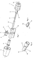
- FIG.1 a schematic overall view of a lock according to the invention in teilzerlegtem state
- Fig.2 an enlarged view of the flyweight hollow shaft
- Figure 3 an embodiment of such a flyweight
- Fig.4 and Fig.5 Sectional views by preferred embodiments of centrifugal weights.
- a knob which is freely rotatably connected via a hollow shaft 2 and a coupling shaft 3 with a housed in another knob 4 electromechanical clutch disc.
- the clutch disc itself may be formed in any desired manner and, for example, magnetically or mechanically coupled with a corresponding component, such as the knob 4.
- the actuating shaft is denoted by 5 and is penetrated by a sliding sleeve 6.
- a locking lug 7 is provided for the operation of the lock bolt, said locking lug 7 is held in the axial direction adjusted by corresponding snap rings 8 and rotatably connected to the actuating shaft 5, which in turn rotatably with the inside knob 4 or after the coupling rotatably connected to the clutch shaft 3 is connected.
- the hollow shaft 2 and the coupling shaft 3 connected thereto can be freely rotated.
- the hollow shaft 2 now has a slot 9, in which a centrifugal weight is inserted, which is spent in a radially outward position with a rapid rotation of the knob 1 about the rotation axis 10 and in this position with a groove 11 in the interior of the lock housing 12 Engage can. In this position, the further rotation of the knob 1 is blocked around the axis 10.
- a flyweight 13 is used, as in Figure 3 is shown enlarged.
- This flyweight 13 carries resilient balls 14, which can engage in groove-like recesses 15 in the interior of the elongated hole 9 in order to ensure a secure rest position.
- a displacement of the centrifugal weight 13 is effected in a radially outward position at an appropriate speed, in which then an entry of the centrifugal weight 13 can be made in the groove 11 of the lock housing 12 and the blockage is effected.
- Figure 5 is in the cross section of the flyweights depending on an oblique edge 17 can be seen, via which the flyweights 13 can be locked by pivoting in the direction of the double arrow 18 each again in the radially inner rest position.
Abstract
Description
Die Erfindung bezieht sich auf ein Schloß mit einer Sicherheitseinrichtung und mit einem Griffteil oder Knauf, welcher im Ruhezustand frei drehbar und im Öffnungs- bzw. Schließzustand mit dem Verriegelungsglied des Schlosses kuppelbar ist, wobei das oder die Fliehgewicht(e) aus einer ersten Rastlage radial auswärts in eine zweite Rastlage verlagerbar sind.The invention relates to a lock with a safety device and a handle part or knob which is freely rotatable in the idle state and in the opening or closing state with the locking member of the lock, wherein the or the centrifugal weight (s) from a first detent position radially be displaced outwards into a second latching position.
Ein derartiges Schloß mit einer Sicherheitseinrichtung ist aus der
Konventionelle Schlösser können mittels eines Schlüssels betätigt werden, wobei durch Verdrehen eines Schlüssels in einem Schloss eine entsprechende Verriegelungsnase verdreht wird, welche einen Riegel in eine Schließposition verschiebt oder aus einer Schließposition in eine Offenposition zurückzieht. Bei elektronischen Sicherheitssystemen treten anstelle des Schlüssels eine Erkennungslogik und ein elektronischer Schlüssel in Form von Karten, Schlüsselanhängern oder anderen Identifikationsmedien. Nach einem Lesen des Schlüssels, welches dem mechanischen Abtasten eines konventionellen Schlüssels entspricht, wird die Drehbewegung eines Knaufes oder Griffes über eine entsprechende Kupplung mit einem weiteren drehbar gelagerten Teil drehfest gekuppelt, welcher in der Folge den Riegel betätigt. In diesem Zusammenhang sind elektronische Sicherheitssysteme bekannt geworden, welche als Doppelknaufzylinder ausgebildet sind, wobei an einer Seite der zu öffnenden Tür Elemente einer Erkennungslogik, und insbesondere Antennen oder dgl., angeordnet sind, wohingegen die Kupplung der Drehbewegung dieses außen liegenden drehbaren Teils nach Erkennen des korrekten Schlüssels über eine Elektronik zumeist auf elektrischem Weg durch Einkuppeln eines Kuppelglieds vorgenommen wird. Bei derartigen Einrichtungen ist ohne eine derartige Kupplung der außen liegende Knauf oder Griff frei drehbar. Dieser frei drehbare Knauf oder Griff ist über eine Welle mit der gegenüberliegenden Seite der Türe oder des Fensters verbunden, an welcher die Kupplung mit dem Betätigungsglied des Schlosses vorgenommen wird. Die Welle wird hierbei mit relativ geringem Spiel durch das Schloss hindurchgeführt, wobei die freie Drehbarkeit bei gleichzeitig relativ geringem Spiel ohne die Gefahr eines Klemmens und ohne die Gefahr einer unbeabsichtigten Kupplung gewährleistet sein muss. Einrichtungen dieser Art sind beispielsweise als Transponderschließsysteme für Schränke und Wertfächer bekannt. Eine mögliche Ausbildung ist beispielsweise der
Bedingt durch die geringen Toleranzen bei der Fertigung derartiger Sicherheitseinrichtungen hat sich aber nun gezeigt, dass eine mögliche missbräuchliche Manipulation dadurch geschaffen wird, dass an den frei drehbaren Griffteil oder Knauf ein entsprechendes Antriebsaggregat, beispielsweise ein elektrischer Motor oder Federwerksmotor, angeschlossen wird, welcher den Griffteil oder Knauf in rasche Rotation versetzt. Bei einer derartigen raschen Rotation wird eine entsprechende Reibungswärme im Inneren des Schlosses generiert, welche bei Ausdehnung der üblicher Weise frei durchdrehenden Welle zu einem Verreiben oder aber einem unbeabsichtigten Kuppeln einer Außenwelle mit einer Innenwelle führen kann, sodass auf diese Weise trotz fehlender elektronischer Freigabe der Kupplung auf mechanischem Weg eine durch thermische Ausdehnung oder Verreiben erzielte Kupplung zwischen dem üblicher Weise frei drehbaren Griffteil oder Knauf und dem Sperrbart entsteht, wodurch das Schloss betätigt werden kann. Eine derartige Fehlbedienung bzw. Sabotagebedienung setzt allerdings voraus, dass der frei drehbare Griffteil oder Knauf über eine Mindestzeit auf eine entsprechende Mindestdrehzahl gebracht werden kann, welche zu einer thermischen Ausdehnung bzw. zum Verreiben führen kann.Due to the low tolerances in the production of such safety devices but has now been shown that a possible improper manipulation is created by the fact that a corresponding drive unit, such as an electric motor or spring mechanism motor is connected to the freely rotatable handle or knob, which the handle part or Knauf in rapid rotation. In such a rapid rotation, a corresponding frictional heat is generated in the interior of the lock, which can lead to rubbing or inadvertent coupling of an outer shaft with an inner shaft upon expansion of the usual way freely spinning shaft, so in this way, despite the lack of electronic release of the clutch mechanically obtained by thermal expansion or trituration coupling between the usual manner freely rotatable handle part or knob and the pawl is formed, whereby the lock can be operated. However, such incorrect operation or sabotage operation requires that the freely rotatable handle or knob over a minimum time to a corresponding Minimum speed can be brought, which can lead to thermal expansion or trituration.
Die Erfindung zielt nun darauf ab, eine derartige Sabotage- bzw. Fehlbedienung mit Sicherheit auszuschließen und zu gewährleisten, dass das frei drehbare Griffteil oder der frei drehbare Knauf nur mit einer relativ geringen Drehgeschwindigkeit frei drehbar bleibt und in anderen Fällen einem Verreiben oder Verklemmen entgegenwirkt.The invention now aims to exclude such sabotage or incorrect operation with certainty and to ensure that the freely rotatable handle part or the freely rotatable knob remains freely rotatable only with a relatively low rotational speed and counteracts rubbing or jamming in other cases.
Zur Lösung dieser Aufgabe besteht die erfindungsgemäße Lösung darin, dass das oder die Fliehgewicht(e) aus einer ersten Rastlage radial auswärts in eine zweite Rastlage verlagerbar sind, wodurch eine präzise Funktion gewährleistet wird.To solve this problem, the solution according to the invention is that the flyweight or the flyweight (s) are displaced radially outwardly from a first detent position into a second detent position, whereby a precise function is ensured.
Dadurch, dass im Inneren des Schlosses eine Fliehkraftverriegelung angeordnet ist, wird nun gewährleistet, dass bei zu hoher Drehzahl des frei drehbaren Griffteils oder Knaufes unmittelbar eine Blockade erfolgt, wobei das mit dem Griffteil oder Knauf gekuppelte Fliehgewicht bei seiner in radialer Richtung geführten Bewegung mit einem ortsfesten Teil des Schlosses in Eingriff gelangt und die weitere Drehbewegung blockiert. Auf Grund der radialen Führung können auch hohe Blockierkräfte mit kleinen Fliehgewichten aufgenommen werden.The fact that a centrifugal force lock is arranged inside the lock, it is now ensured that at high speed of the freely rotatable handle or knob directly blockage takes place, the coupled with the handle or knob centrifugal weight at its guided in the radial direction movement with a stationary part of the lock engages and blocks the further rotation. Due to the radial guidance and high blocking forces can be absorbed with small centrifugal weights.
Gemäß einer bevorzugten Weiterbildung des erfindungsgemäßen Schlosses ist die Ausbildung so getroffen, dass der Griffteil oder Knauf mit einer in das Gehäuse des Schlosses eintauchenden Welle verbunden ist, welche wenigstens eine radiale Durchbrechung aufweist, in welcher ein Fliehgewicht mit einer außerhalb der Drehachse liegenden Schwerpunktslage angeordnet ist und dass im Gehäuse des Schlosses eine Ausnehmung oder Nut angeordnet ist, in welche das Fliehgewicht bei einer radialen Bewegung desselben eintaucht. Bei einer derartigen Konstruktion wird das Fliehgewicht in einer exzentrischen Ruhelage gehalten, sodass eine genau definierte Fliehkraft ausreicht, um es aus dieser Ruhelage in eine radial weiter auswärts liegende Sperrposition zu verlagern. In besonders einfacher Weise kann die Ausbildung hierbei so getroffen sein, dass das Fliehgewicht in einem Langloch der Welle gelagert ist, wobei vorzugsweise die Welle als Hohlwelle ausgebildet ist und drehfest mit einer das Schloss durchsetzenden Kupplungswelle für die Kupplung mit dem Verriegelungsglied des Schlosses verbunden ist. Die Lagerung des Fliehgewichts in der Hohlwelle, welches selbst mit der Kupplungswelle verbunden ist, gewährleistet gleichzeitig die entsprechende exzentrische Lage des Fliehgewichts in der Ruheposition bzw. Ausgangsposition.According to a preferred embodiment of the lock according to the invention, the design is such that the handle part or knob is connected to a dipping into the housing of the lock shaft having at least one radial opening in which a centrifugal weight is arranged with a lying outside the axis of rotation center of gravity and that in the housing of the lock, a recess or groove is arranged, in which the flyweight dips in a radial movement of the same. In such a construction, the flyweight is in one held eccentric rest position so that a well-defined centrifugal force is sufficient to move it from this rest position in a radially outward locking position. In a particularly simple manner, the training may in this case be such that the centrifugal weight is mounted in a slot of the shaft, wherein preferably the shaft is formed as a hollow shaft and rotatably connected to a lock passing through the coupling shaft for the coupling with the locking member of the castle. The storage of the centrifugal weight in the hollow shaft, which is itself connected to the coupling shaft, at the same time ensuring the corresponding eccentric position of the centrifugal weight in the rest position or starting position.
Um die Reibungsverluste des Fliehgewichts möglichst gering zu halten und eine definierte Ausgangsposition sicherzustellen, ist die Ausbildung mit Vorteil zu getroffen, dass das Fliehgewicht unter Zwischenschaltung von federnden Rastkugeln im Langloch der Welle gehalten ist.In order to keep the friction losses of the centrifugal weight as low as possible and to ensure a defined starting position, the training is advantageously taken to ensure that the centrifugal weight is held with the interposition of resilient locking balls in the slot of the shaft.
Die exakte Position kann in beiden Lagen der Fliehgewichte dadurch in besonders einfacher Weise sichergestellt werden, dass an den Wänden des Langloches Nuten für das Einrasten der Rastkugeln in einer radial inneren Ruhelage und einer radial außen liegenden Verriegelungslage vorgesehen sind.The exact position can be ensured in two positions of the centrifugal weights in a particularly simple manner that are provided on the walls of the elongated hole grooves for the engagement of the locking balls in a radially inner rest position and a radially outer locking position.
Eine sichere Rückkehr der Fliegewichte aus ihrer Sperrlage in die Ruhelage kann dadurch erzielt werden, dass die radial verlagerten Fliegewichte im Axialschnitt jeweils abgeschrägte Kanten aufweisen, über welche die Fliegewichte durch Verdrehen entgegen der die Verriegelung bewirkenden Drehrichtung aus der radial äußeren Rastlage in die radial innere Ruhelage drückbar sind, wobei vorzugsweise in Umfangsrichtung benachbarte bzw. gegenüberliegende Fliehgewichte Schrägflächen tragen, die eine Freigabe der Blockade nur bei zwei Drehbewegungen in jeweils entgegengesetzte Drehrichtung bewirken.A safe return of the flyweights from their locked position to the rest position can be achieved that the radially displaced flow weights each have beveled edges in axial section over which the flyweights by turning against the locking effecting direction of rotation of the radially outer detent position in the radially inner rest position can be pressed, preferably bearing in the circumferential direction adjacent or opposite centrifugal weights inclined surfaces, which cause a release of the blockade only in two rotational movements in the opposite direction of rotation.
Die Erfindung wird nachfolgend anhand eines in der Zeichnung schematisch dargestellten Ausführungsbeispiels näher erläutert. In dieser zeigen
In
Ohne eine entsprechende Kupplung der Betätigungswelle 5 mit dem Knauf 1 kann die Hohlwelle 2 und die damit verbundene Kupplungswelle 3 frei verdreht werden. Die Hohlwelle 2 weist nun ein Langloch 9 auf, in welches ein Fliehgewicht eingelegt ist, welches bei einem raschen Verdrehen des Knaufs 1 um die Rotationsachse 10 in eine radial auswärtige Position verbracht wird und in dieser Position mit einer Nut 11 im Inneren des Schlossgehäuses 12 zum Eingriff gelangen kann. In dieser Position wird die weitere Drehbewegung des Knaufs 1 um die Achse 10 blockiert.Without a corresponding coupling of the actuating
In der Darstellung nach
Bei der Darstellung nach
In
Claims (8)
- Lock having a security device comprising a grip portion or knob which is freely rotatable in the resting state and can be coupled to the locking member of the lock in the open or closed state, wherein at least one radially guided displaceable flyweight (13) is coupled to the grip portion or knob (1), which engages with a fixed portion (11) of the lock and blocks any further rotary movement above a defined number of revolutions of the grip portion or knob (1) per unit time, characterised in that the flyweight or flyweights (13) can be displaced from a first locking position radially outwards into a second locking position.
- Lock according to claim 1, characterised in that the grip portion or knob (1) is connected to a shaft (2) which dips into the housing of a lock, which has at least one radial opening (9) in which a flyweight (13) is arranged with a centre of gravity located outside the axis of rotation (10) and that a recess or groove (11) is arranged in the housing (12) of the lock into which the flyweight (13) dips during a radial movement of the same.
- Lock according to claim 1 or 2, characterised in that the shaft is configured as a hollow shaft (2) and is connected rotationally fixedly to a coupling shaft (3) which passes through the lock for coupling with the locking member (7) of the lock.
- Lock according to any one of claims 1 to 3, characterised in that the flyweight (13) is mounted in an elongated hole (9) of the shaft.
- Lock according to any one of claims 1 to 4, characterised in that the flyweight (13) is held in said elongated hole (9) of the shaft (2) with interposed spring-mounted locking balls (14).
- Lock according to any one of claims 1 to 5, characterised in that grooves (15) for engagement of the locking balls (14) in a radially inner resting position and a radially outer locking position are provided on the walls of the elongated hole (9).
- Lock according to any one of claims 1 to 6, characterised in that the radially displaced flyweights (13) each have bevelled edges (17) in the axial section, by which means the flyweights (13) can be pressed from the radially outer locking position into the radially inner resting position by turning in the direction opposite to the direction of rotation effecting the locking.
- Lock according to claim 7, characterised in that neighbouring or opposite flyweights (13) in the circumferential direction preferably have sloping surfaces (17) which only effect a release of the blocking during two rotating movements in respectively opposite directions of rotation.
Applications Claiming Priority (2)
| Application Number | Priority Date | Filing Date | Title |
|---|---|---|---|
| AT0029206A AT501753B1 (en) | 2006-02-22 | 2006-02-22 | SAFETY DEVICE FOR LOCKS |
| PCT/AT2007/000073 WO2007095652A1 (en) | 2006-02-22 | 2007-02-13 | Safety mechanism for locks |
Publications (2)
| Publication Number | Publication Date |
|---|---|
| EP1987218A1 EP1987218A1 (en) | 2008-11-05 |
| EP1987218B1 true EP1987218B1 (en) | 2010-06-16 |
Family
ID=37192197
Family Applications (1)
| Application Number | Title | Priority Date | Filing Date |
|---|---|---|---|
| EP20070701317 Not-in-force EP1987218B1 (en) | 2006-02-22 | 2007-02-13 | Lock with safety system |
Country Status (11)
| Country | Link |
|---|---|
| US (1) | US20090013734A1 (en) |
| EP (1) | EP1987218B1 (en) |
| JP (1) | JP2009527663A (en) |
| CN (1) | CN101384784A (en) |
| AT (2) | AT501753B1 (en) |
| AU (1) | AU2007219023A1 (en) |
| CA (1) | CA2641905A1 (en) |
| DE (1) | DE502007004130D1 (en) |
| ES (1) | ES2347014T3 (en) |
| MX (1) | MX2008010790A (en) |
| WO (1) | WO2007095652A1 (en) |
Families Citing this family (12)
| Publication number | Priority date | Publication date | Assignee | Title |
|---|---|---|---|---|
| JP5394981B2 (en) * | 2010-05-13 | 2014-01-22 | 株式会社東海理化電機製作所 | Ignition switch operation restriction device |
| US11193142B2 (en) | 2011-10-24 | 2021-12-07 | AgorFora ApS | Methods and apparatus for hydrogen based biogas upgrading |
| AT512658B1 (en) * | 2012-05-10 | 2013-10-15 | Evva Sicherheitstechnologie | Safety device for locks |
| WO2013191676A1 (en) * | 2012-06-18 | 2013-12-27 | Smoot Max M | Self-locking hitch pin |
| IL226186B (en) | 2013-05-06 | 2019-02-28 | Mul T Lock Technologies Ltd | Electromechaincal cylinder lock with key override |
| AT514596B1 (en) | 2013-06-18 | 2015-02-15 | Evva Sicherheitstechnologie | Safety device for locking device |
| AT514538B1 (en) | 2013-06-25 | 2015-07-15 | Evva Sicherheitstechnologie | Safety device for lock cylinder |
| AT514539B1 (en) | 2013-07-04 | 2015-05-15 | Evva Sicherheitstechnologie | Safety device for locking devices |
| ES2600925T3 (en) * | 2013-10-08 | 2017-02-13 | Assa Oem Ab | Doorknob device |
| CN107119999A (en) * | 2017-06-12 | 2017-09-01 | 南京格锐盖特门业有限公司 | A kind of automatic lock core structure |
| US10253528B1 (en) * | 2018-02-21 | 2019-04-09 | Axtuator OY | Digital lock |
| CN111197431A (en) * | 2019-12-30 | 2020-05-26 | 厦门美科物联科技有限公司 | Novel electronic lock structure |
Family Cites Families (20)
| Publication number | Priority date | Publication date | Assignee | Title |
|---|---|---|---|---|
| US2301751A (en) * | 1940-05-29 | 1942-11-10 | Schlage Lock Co | Demountable knob and cylinder lock |
| US3212306A (en) * | 1964-01-06 | 1965-10-19 | Russell | Combination hand-hold retainer and key-operated mechanism retainer |
| US3293892A (en) * | 1964-10-09 | 1966-12-27 | Independent Lock Co | Lock adapter |
| US4142388A (en) * | 1977-03-30 | 1979-03-06 | Klaus W. Gartner | Tumbler wheels for combination locks |
| US4679418A (en) * | 1984-12-26 | 1987-07-14 | Allen Mark L | High security cylinder lock |
| US5061923A (en) * | 1988-09-29 | 1991-10-29 | C & M Technology, Inc. | Computerized combination lock |
| US4966399A (en) * | 1989-04-19 | 1990-10-30 | Lin Jui C | Lock set with spindle lock |
| US5077994A (en) * | 1991-04-05 | 1992-01-07 | Yale Security Inc. | Door lock having removable outside lever handle for the purpose of changing the key cylinder |
| EP0523262A1 (en) * | 1991-07-15 | 1993-01-20 | Loxit Industrial Technologies, Ltd. | Device for pickproofing combination locks |
| CA2097992A1 (en) * | 1993-06-08 | 1994-12-09 | Ilan Goldman | Combination lock with arrangement for defeating automatic dialer |
| CZ289889B6 (en) * | 1994-03-04 | 2002-04-17 | Ernst Keller | Lock installation |
| GB9417748D0 (en) * | 1994-09-03 | 1994-10-19 | Yale Security Prod Ltd | Electrically operable cylinder lock |
| US5782119A (en) * | 1996-07-19 | 1998-07-21 | Baldwin Hardware Corporation | Biased detent for door knob assembly |
| DE19861400B4 (en) * | 1997-11-07 | 2013-08-01 | Simonsvoss Technologies Ag | lock cylinder |
| US5921122A (en) * | 1998-05-27 | 1999-07-13 | Taiwan Fu Hsing Industry Co. Ltd. | Device for preventing falling of upper pin tumblers of a lock during change of a lock core in the lock |
| US6014877A (en) * | 1999-02-08 | 2000-01-18 | Shen; Mu-Lin | Core retainer for a lock with an interchangeable lock core |
| US6742367B2 (en) * | 2002-08-19 | 2004-06-01 | Taiwan Fu Hsing Industrial Co., Ltd | Inside locking device of flat handle lock |
| US7156432B2 (en) * | 2004-05-24 | 2007-01-02 | Newfrey, Llc | Operator catch cartridge assembly for a door handle set |
| ITTO20040584A1 (en) * | 2004-09-03 | 2004-12-03 | Giobert Spa | LOCK WITH ANTI-TORSION SAFETY DEVICE |
| US7428836B2 (en) * | 2006-01-17 | 2008-09-30 | Zhen-Lin Yang | Door lock having reinforced strength |
-
2006
- 2006-02-22 AT AT0029206A patent/AT501753B1/en not_active IP Right Cessation
-
2007
- 2007-02-13 CN CNA2007800059802A patent/CN101384784A/en active Pending
- 2007-02-13 MX MX2008010790A patent/MX2008010790A/en not_active Application Discontinuation
- 2007-02-13 EP EP20070701317 patent/EP1987218B1/en not_active Not-in-force
- 2007-02-13 DE DE200750004130 patent/DE502007004130D1/en active Active
- 2007-02-13 CA CA 2641905 patent/CA2641905A1/en not_active Abandoned
- 2007-02-13 ES ES07701317T patent/ES2347014T3/en active Active
- 2007-02-13 AU AU2007219023A patent/AU2007219023A1/en not_active Abandoned
- 2007-02-13 JP JP2008555557A patent/JP2009527663A/en not_active Abandoned
- 2007-02-13 AT AT07701317T patent/ATE471420T1/en active
- 2007-02-13 US US12/224,200 patent/US20090013734A1/en not_active Abandoned
- 2007-02-13 WO PCT/AT2007/000073 patent/WO2007095652A1/en active Application Filing
Also Published As
| Publication number | Publication date |
|---|---|
| ATE471420T1 (en) | 2010-07-15 |
| MX2008010790A (en) | 2008-09-01 |
| CN101384784A (en) | 2009-03-11 |
| US20090013734A1 (en) | 2009-01-15 |
| AU2007219023A1 (en) | 2007-08-30 |
| EP1987218A1 (en) | 2008-11-05 |
| WO2007095652A1 (en) | 2007-08-30 |
| ES2347014T3 (en) | 2010-10-22 |
| AT501753B1 (en) | 2006-11-15 |
| JP2009527663A (en) | 2009-07-30 |
| AT501753A4 (en) | 2006-11-15 |
| CA2641905A1 (en) | 2007-08-30 |
| DE502007004130D1 (en) | 2010-07-29 |
Similar Documents
| Publication | Publication Date | Title |
|---|---|---|
| EP1987218B1 (en) | Lock with safety system | |
| EP2473690B1 (en) | Closing device | |
| EP2391786B1 (en) | Lock-box | |
| AT507583B1 (en) | LOCKS | |
| EP2175166A2 (en) | Locking device | |
| EP3404172B1 (en) | Safety mechanism for locks | |
| EP2171202B1 (en) | Access lock | |
| EP2821568B1 (en) | Locking device, particularly lock cylinder | |
| EP2818611B1 (en) | Locking cylinder with a safety device | |
| EP2816180B1 (en) | Safety device for locking device | |
| WO2007022910A2 (en) | Unlocking and locking element | |
| EP3396641B1 (en) | Locking system | |
| DE2528712A1 (en) | Locking mechanism for e.g. doors - has housing with locking rotor operating locking element and overload friction coupling fitted between two | |
| EP1164238A1 (en) | Cylinder lock | |
| EP0943762A2 (en) | Locking/unlocking device with mechanical and electrical encoding | |
| EP3521682B9 (en) | Safety switch | |
| EP2652228B1 (en) | Combined mechanical and electronic key for a vehicle with a pawl, functioning as a positioning wing element | |
| DE102007063582A1 (en) | Locking device for e.g. room door, has rotating angle limiter assigned for cylinder movement, where limiter is conquerable during usage of key, which is provided with recess that permits limiter to pass plane of key | |
| EP3889918A1 (en) | Lock cylinder for a game machine, game machine and method | |
| DE102022114905A1 (en) | Lock with a bolt that can be rotated by an operating element | |
| EP4112856A1 (en) | Lock with a bolt rotatable by an actuating element | |
| DE10207649B4 (en) | Electrically controlled lock | |
| EP4311900A1 (en) | Locking system with mechatronic locking cylinder and a mechatronic key | |
| DE102013103047A1 (en) | coupling device | |
| EP2458117A2 (en) | Protective fitting for windows |
Legal Events
| Date | Code | Title | Description |
|---|---|---|---|
| PUAI | Public reference made under article 153(3) epc to a published international application that has entered the european phase |
Free format text: ORIGINAL CODE: 0009012 |
|
| 17P | Request for examination filed |
Effective date: 20080722 |
|
| AK | Designated contracting states |
Kind code of ref document: A1 Designated state(s): AT BE BG CH CY CZ DE DK EE ES FI FR GB GR HU IE IS IT LI LT LU LV MC NL PL PT RO SE SI SK TR |
|
| RAP1 | Party data changed (applicant data changed or rights of an application transferred) |
Owner name: EVVA-WERK SPEZIALERZEUGUNG VON ZYLINDER- UND SICHE |
|
| 17Q | First examination report despatched |
Effective date: 20081203 |
|
| RTI1 | Title (correction) |
Free format text: LOCK WITH SAFETY SYSTEM |
|
| RAP1 | Party data changed (applicant data changed or rights of an application transferred) |
Owner name: EVVA SICHERHEITSTECHNOLOGIE GMBH |
|
| GRAP | Despatch of communication of intention to grant a patent |
Free format text: ORIGINAL CODE: EPIDOSNIGR1 |
|
| GRAS | Grant fee paid |
Free format text: ORIGINAL CODE: EPIDOSNIGR3 |
|
| GRAA | (expected) grant |
Free format text: ORIGINAL CODE: 0009210 |
|
| DAX | Request for extension of the european patent (deleted) | ||
| DAX | Request for extension of the european patent (deleted) | ||
| AK | Designated contracting states |
Kind code of ref document: B1 Designated state(s): AT BE BG CH CY CZ DE DK EE ES FI FR GB GR HU IE IS IT LI LT LU LV MC NL PL PT RO SE SI SK TR |
|
| REG | Reference to a national code |
Ref country code: CH Ref legal event code: NV Representative=s name: OK PAT AG PATENTE MARKEN LIZENZEN Ref country code: CH Ref legal event code: EP |
|
| REG | Reference to a national code |
Ref country code: IE Ref legal event code: FG4D Free format text: LANGUAGE OF EP DOCUMENT: GERMAN |
|
| REF | Corresponds to: |
Ref document number: 502007004130 Country of ref document: DE Date of ref document: 20100729 Kind code of ref document: P |
|
| REG | Reference to a national code |
Ref country code: NL Ref legal event code: T3 |
|
| REG | Reference to a national code |
Ref country code: SE Ref legal event code: TRGR |
|
| REG | Reference to a national code |
Ref country code: ES Ref legal event code: FG2A Ref document number: 2347014 Country of ref document: ES Kind code of ref document: T3 |
|
| PG25 | Lapsed in a contracting state [announced via postgrant information from national office to epo] |
Ref country code: LT Free format text: LAPSE BECAUSE OF FAILURE TO SUBMIT A TRANSLATION OF THE DESCRIPTION OR TO PAY THE FEE WITHIN THE PRESCRIBED TIME-LIMIT Effective date: 20100616 |
|
| LTIE | Lt: invalidation of european patent or patent extension |
Effective date: 20100616 |
|
| PG25 | Lapsed in a contracting state [announced via postgrant information from national office to epo] |
Ref country code: LV Free format text: LAPSE BECAUSE OF FAILURE TO SUBMIT A TRANSLATION OF THE DESCRIPTION OR TO PAY THE FEE WITHIN THE PRESCRIBED TIME-LIMIT Effective date: 20100616 Ref country code: SI Free format text: LAPSE BECAUSE OF FAILURE TO SUBMIT A TRANSLATION OF THE DESCRIPTION OR TO PAY THE FEE WITHIN THE PRESCRIBED TIME-LIMIT Effective date: 20100616 Ref country code: FI Free format text: LAPSE BECAUSE OF FAILURE TO SUBMIT A TRANSLATION OF THE DESCRIPTION OR TO PAY THE FEE WITHIN THE PRESCRIBED TIME-LIMIT Effective date: 20100616 |
|
| PG25 | Lapsed in a contracting state [announced via postgrant information from national office to epo] |
Ref country code: CY Free format text: LAPSE BECAUSE OF FAILURE TO SUBMIT A TRANSLATION OF THE DESCRIPTION OR TO PAY THE FEE WITHIN THE PRESCRIBED TIME-LIMIT Effective date: 20100616 Ref country code: PL Free format text: LAPSE BECAUSE OF FAILURE TO SUBMIT A TRANSLATION OF THE DESCRIPTION OR TO PAY THE FEE WITHIN THE PRESCRIBED TIME-LIMIT Effective date: 20100616 |
|
| REG | Reference to a national code |
Ref country code: IE Ref legal event code: FD4D |
|
| PG25 | Lapsed in a contracting state [announced via postgrant information from national office to epo] |
Ref country code: EE Free format text: LAPSE BECAUSE OF FAILURE TO SUBMIT A TRANSLATION OF THE DESCRIPTION OR TO PAY THE FEE WITHIN THE PRESCRIBED TIME-LIMIT Effective date: 20100616 Ref country code: IE Free format text: LAPSE BECAUSE OF FAILURE TO SUBMIT A TRANSLATION OF THE DESCRIPTION OR TO PAY THE FEE WITHIN THE PRESCRIBED TIME-LIMIT Effective date: 20100616 |
|
| PG25 | Lapsed in a contracting state [announced via postgrant information from national office to epo] |
Ref country code: SK Free format text: LAPSE BECAUSE OF FAILURE TO SUBMIT A TRANSLATION OF THE DESCRIPTION OR TO PAY THE FEE WITHIN THE PRESCRIBED TIME-LIMIT Effective date: 20100616 Ref country code: IS Free format text: LAPSE BECAUSE OF FAILURE TO SUBMIT A TRANSLATION OF THE DESCRIPTION OR TO PAY THE FEE WITHIN THE PRESCRIBED TIME-LIMIT Effective date: 20101016 Ref country code: PT Free format text: LAPSE BECAUSE OF FAILURE TO SUBMIT A TRANSLATION OF THE DESCRIPTION OR TO PAY THE FEE WITHIN THE PRESCRIBED TIME-LIMIT Effective date: 20101018 Ref country code: RO Free format text: LAPSE BECAUSE OF FAILURE TO SUBMIT A TRANSLATION OF THE DESCRIPTION OR TO PAY THE FEE WITHIN THE PRESCRIBED TIME-LIMIT Effective date: 20100616 |
|
| PLBE | No opposition filed within time limit |
Free format text: ORIGINAL CODE: 0009261 |
|
| STAA | Information on the status of an ep patent application or granted ep patent |
Free format text: STATUS: NO OPPOSITION FILED WITHIN TIME LIMIT |
|
| PG25 | Lapsed in a contracting state [announced via postgrant information from national office to epo] |
Ref country code: DK Free format text: LAPSE BECAUSE OF FAILURE TO SUBMIT A TRANSLATION OF THE DESCRIPTION OR TO PAY THE FEE WITHIN THE PRESCRIBED TIME-LIMIT Effective date: 20100616 |
|
| 26N | No opposition filed |
Effective date: 20110317 |
|
| PG25 | Lapsed in a contracting state [announced via postgrant information from national office to epo] |
Ref country code: GR Free format text: LAPSE BECAUSE OF FAILURE TO SUBMIT A TRANSLATION OF THE DESCRIPTION OR TO PAY THE FEE WITHIN THE PRESCRIBED TIME-LIMIT Effective date: 20100917 |
|
| REG | Reference to a national code |
Ref country code: DE Ref legal event code: R097 Ref document number: 502007004130 Country of ref document: DE Effective date: 20110316 |
|
| BERE | Be: lapsed |
Owner name: EVVA SICHERHEITSTECHNOLOGIE GMBH Effective date: 20110228 |
|
| PG25 | Lapsed in a contracting state [announced via postgrant information from national office to epo] |
Ref country code: MC Free format text: LAPSE BECAUSE OF NON-PAYMENT OF DUE FEES Effective date: 20110228 |
|
| PG25 | Lapsed in a contracting state [announced via postgrant information from national office to epo] |
Ref country code: BE Free format text: LAPSE BECAUSE OF NON-PAYMENT OF DUE FEES Effective date: 20110228 |
|
| REG | Reference to a national code |
Ref country code: AT Ref legal event code: MM01 Ref document number: 471420 Country of ref document: AT Kind code of ref document: T Effective date: 20120213 |
|
| PG25 | Lapsed in a contracting state [announced via postgrant information from national office to epo] |
Ref country code: LU Free format text: LAPSE BECAUSE OF NON-PAYMENT OF DUE FEES Effective date: 20110213 |
|
| PG25 | Lapsed in a contracting state [announced via postgrant information from national office to epo] |
Ref country code: AT Free format text: LAPSE BECAUSE OF NON-PAYMENT OF DUE FEES Effective date: 20120213 |
|
| PG25 | Lapsed in a contracting state [announced via postgrant information from national office to epo] |
Ref country code: BG Free format text: LAPSE BECAUSE OF FAILURE TO SUBMIT A TRANSLATION OF THE DESCRIPTION OR TO PAY THE FEE WITHIN THE PRESCRIBED TIME-LIMIT Effective date: 20100916 Ref country code: TR Free format text: LAPSE BECAUSE OF FAILURE TO SUBMIT A TRANSLATION OF THE DESCRIPTION OR TO PAY THE FEE WITHIN THE PRESCRIBED TIME-LIMIT Effective date: 20100616 |
|
| PG25 | Lapsed in a contracting state [announced via postgrant information from national office to epo] |
Ref country code: HU Free format text: LAPSE BECAUSE OF FAILURE TO SUBMIT A TRANSLATION OF THE DESCRIPTION OR TO PAY THE FEE WITHIN THE PRESCRIBED TIME-LIMIT Effective date: 20100616 |
|
| REG | Reference to a national code |
Ref country code: FR Ref legal event code: PLFP Year of fee payment: 9 |
|
| PGFP | Annual fee paid to national office [announced via postgrant information from national office to epo] |
Ref country code: ES Payment date: 20150226 Year of fee payment: 9 Ref country code: IT Payment date: 20150223 Year of fee payment: 9 Ref country code: NL Payment date: 20150225 Year of fee payment: 9 Ref country code: CZ Payment date: 20150206 Year of fee payment: 9 Ref country code: CH Payment date: 20150226 Year of fee payment: 9 |
|
| PGFP | Annual fee paid to national office [announced via postgrant information from national office to epo] |
Ref country code: SE Payment date: 20150226 Year of fee payment: 9 Ref country code: FR Payment date: 20150217 Year of fee payment: 9 Ref country code: GB Payment date: 20150226 Year of fee payment: 9 |
|
| REG | Reference to a national code |
Ref country code: CH Ref legal event code: PL |
|
| REG | Reference to a national code |
Ref country code: SE Ref legal event code: EUG |
|
| GBPC | Gb: european patent ceased through non-payment of renewal fee |
Effective date: 20160213 |
|
| PG25 | Lapsed in a contracting state [announced via postgrant information from national office to epo] |
Ref country code: LI Free format text: LAPSE BECAUSE OF NON-PAYMENT OF DUE FEES Effective date: 20160229 Ref country code: CH Free format text: LAPSE BECAUSE OF NON-PAYMENT OF DUE FEES Effective date: 20160229 |
|
| REG | Reference to a national code |
Ref country code: NL Ref legal event code: MM Effective date: 20160301 |
|
| REG | Reference to a national code |
Ref country code: FR Ref legal event code: ST Effective date: 20161028 |
|
| PG25 | Lapsed in a contracting state [announced via postgrant information from national office to epo] |
Ref country code: SE Free format text: LAPSE BECAUSE OF NON-PAYMENT OF DUE FEES Effective date: 20160214 Ref country code: CZ Free format text: LAPSE BECAUSE OF NON-PAYMENT OF DUE FEES Effective date: 20160213 |
|
| PG25 | Lapsed in a contracting state [announced via postgrant information from national office to epo] |
Ref country code: IT Free format text: LAPSE BECAUSE OF NON-PAYMENT OF DUE FEES Effective date: 20160213 |
|
| PG25 | Lapsed in a contracting state [announced via postgrant information from national office to epo] |
Ref country code: NL Free format text: LAPSE BECAUSE OF NON-PAYMENT OF DUE FEES Effective date: 20160301 Ref country code: FR Free format text: LAPSE BECAUSE OF NON-PAYMENT OF DUE FEES Effective date: 20160229 Ref country code: GB Free format text: LAPSE BECAUSE OF NON-PAYMENT OF DUE FEES Effective date: 20160213 |
|
| PGFP | Annual fee paid to national office [announced via postgrant information from national office to epo] |
Ref country code: DE Payment date: 20170227 Year of fee payment: 11 |
|
| PG25 | Lapsed in a contracting state [announced via postgrant information from national office to epo] |
Ref country code: ES Free format text: LAPSE BECAUSE OF NON-PAYMENT OF DUE FEES Effective date: 20160214 |
|
| REG | Reference to a national code |
Ref country code: DE Ref legal event code: R119 Ref document number: 502007004130 Country of ref document: DE |
|
| REG | Reference to a national code |
Ref country code: ES Ref legal event code: FD2A Effective date: 20181207 |
|
| PG25 | Lapsed in a contracting state [announced via postgrant information from national office to epo] |
Ref country code: DE Free format text: LAPSE BECAUSE OF NON-PAYMENT OF DUE FEES Effective date: 20180901 |