EP3404172B1 - Safety mechanism for locks - Google Patents
Safety mechanism for locks Download PDFInfo
- Publication number
- EP3404172B1 EP3404172B1 EP18000496.2A EP18000496A EP3404172B1 EP 3404172 B1 EP3404172 B1 EP 3404172B1 EP 18000496 A EP18000496 A EP 18000496A EP 3404172 B1 EP3404172 B1 EP 3404172B1
- Authority
- EP
- European Patent Office
- Prior art keywords
- handle
- eddy current
- shaft
- coupling
- lock
- Prior art date
- Legal status (The legal status is an assumption and is not a legal conclusion. Google has not performed a legal analysis and makes no representation as to the accuracy of the status listed.)
- Active
Links
Images

Classifications
-
- E—FIXED CONSTRUCTIONS
- E05—LOCKS; KEYS; WINDOW OR DOOR FITTINGS; SAFES
- E05B—LOCKS; ACCESSORIES THEREFOR; HANDCUFFS
- E05B13/00—Devices preventing the key or the handle or both from being used
- E05B13/005—Disconnecting the handle
-
- E—FIXED CONSTRUCTIONS
- E05—LOCKS; KEYS; WINDOW OR DOOR FITTINGS; SAFES
- E05B—LOCKS; ACCESSORIES THEREFOR; HANDCUFFS
- E05B17/00—Accessories in connection with locks
- E05B17/20—Means independent of the locking mechanism for preventing unauthorised opening, e.g. for securing the bolt in the fastening position
- E05B17/2084—Means to prevent forced opening by attack, tampering or jimmying
-
- E—FIXED CONSTRUCTIONS
- E05—LOCKS; KEYS; WINDOW OR DOOR FITTINGS; SAFES
- E05B—LOCKS; ACCESSORIES THEREFOR; HANDCUFFS
- E05B47/00—Operating or controlling locks or other fastening devices by electric or magnetic means
- E05B47/06—Controlling mechanically-operated bolts by electro-magnetically-operated detents
- E05B47/0611—Cylinder locks with electromagnetic control
- E05B47/0615—Cylinder locks with electromagnetic control operated by handles, e.g. by knobs
-
- E—FIXED CONSTRUCTIONS
- E05—LOCKS; KEYS; WINDOW OR DOOR FITTINGS; SAFES
- E05B—LOCKS; ACCESSORIES THEREFOR; HANDCUFFS
- E05B47/00—Operating or controlling locks or other fastening devices by electric or magnetic means
- E05B47/06—Controlling mechanically-operated bolts by electro-magnetically-operated detents
- E05B47/0676—Controlling mechanically-operated bolts by electro-magnetically-operated detents by disconnecting the handle
-
- E—FIXED CONSTRUCTIONS
- E05—LOCKS; KEYS; WINDOW OR DOOR FITTINGS; SAFES
- E05B—LOCKS; ACCESSORIES THEREFOR; HANDCUFFS
- E05B9/00—Lock casings or latch-mechanism casings ; Fastening locks or fasteners or parts thereof to the wing
- E05B9/04—Casings of cylinder locks
- E05B9/041—Double cylinder locks
-
- E—FIXED CONSTRUCTIONS
- E05—LOCKS; KEYS; WINDOW OR DOOR FITTINGS; SAFES
- E05B—LOCKS; ACCESSORIES THEREFOR; HANDCUFFS
- E05B47/00—Operating or controlling locks or other fastening devices by electric or magnetic means
- E05B47/0001—Operating or controlling locks or other fastening devices by electric or magnetic means with electric actuators; Constructional features thereof
- E05B2047/0014—Constructional features of actuators or power transmissions therefor
- E05B2047/0018—Details of actuator transmissions
- E05B2047/0026—Clutches, couplings or braking arrangements
Definitions
- the invention relates to a security device for locks with a handle, which is freely rotatable in the idle state and can be coupled to the locking member of the lock in the actuated state, a braking or blocking device being provided which, from a defined number of revolutions of the handle in a unit time, the further Rotational movement brakes or blocks.
- Conventional locks can be actuated by means of a key, wherein by turning a key in a lock a corresponding locking lug is rotated, which moves a bolt into a closed position or withdraws it from a closed position into an open position.
- recognition logic and an electronic key in the form of cards or other identification media replace the key.
- the rotary movement of a handle is rotatably coupled via a corresponding coupling to a further rotatably mounted part, which subsequently actuates the bolt.
- electronic security systems which are designed as double knob cylinders, elements of a detection logic, and in particular antennas or the like, being arranged on one side of the door to be opened, whereas the coupling of the rotary movement of this external rotatable part after detection of the correct key via electronics is usually done electrically by coupling a coupling element.
- the external handle can be freely rotated without such a coupling.
- This freely rotatable handle is connected via a shaft to the opposite side of the door or window, on which the coupling is carried out with the actuator of the lock.
- the shaft is guided through the lock with relatively little play, whereby the free rotation with a relatively small play must be ensured without the risk of jamming and without the risk of an unintentional coupling.
- One possible training is, for example DE 19851308 A1 can be seen in which the locking cylinder is provided on both sides with knobs, of which the inside knob has an access control electronics.
- an access authorization is determined, with a clutch being actuated electromagnetically in such a way that a lock bit can be moved from the outside rotary knob.
- the invention therefore aims to improve a safety device of the type mentioned at the outset in such a way that the functionality is ensured even at very high rotational speeds and at high torques which are applied to the handle.
- the security device should function largely independently of the external forces acting on the lock.
- the invention provides in a safety device of the type mentioned at the outset that the braking or blocking device is designed as an eddy current brake.
- the eddy current brake here has in particular a magnetic element and an eddy current element, the magnetic element either having at least one permanent magnet or an electromagnet which is switched on when a certain speed of the handle is exceeded, as a result of which the eddy current brake applies a torque which is opposite to the torque of the handle.
- the Actuating shaft is designed as a hollow shaft, which is penetrated by the coupling shaft.
- a safety device of the type mentioned at the outset comprising an element which can be displaced between a release position and a braking or blocking position and which, in the braking or blocking position, interacts with a counter-element in order to further rotate to brake or block
- the handle is mechanically decoupled from the displaceable element in its release position.
- the mechanical decoupling ensures that external forces acting on the handle and the shaft possibly connected to the handle do not affect the part responsible for applying the braking torque or blocking, namely the displaceable element of the braking or blocking device can be transferred. Manipulation or damage due to violence is therefore excluded.
- the displaceable element is thus structurally separated from the handle or an element connected in a rotationally fixed manner to the handle, in particular in the release position, and in particular does not rotate with the handle.
- the displaceable element interacts only in the braking or blocking position with the handle or with a part that is coupled in a rotationally fixed manner to the handle in order to brake or block the further rotary movement.
- This safety device includes versions in which the detection device for detecting the rotational speed of the handle is different from the braking or blocking device, in particular is mechanically decoupled.
- the braking or blocking device is therefore not subject to the geometric and material restrictions of the torque detection device and can therefore be designed to be more stable.
- the mechanical decoupling of the rotary movement of the handle from the displaceable element is preferably achieved in that a drive for displacing the displaceable element between the release position and the braking or blocking position is provided, which is in motion by contactless, in particular magnetic coupling with the rotary movement of the handle is relocatable.
- the contactless coupling is preferably formed by an eddy current coupling driven by the rotary movement of the handle.
- the contactless coupling can comprise an electrical generator which is driven by the rotary movement of the handle and which provides an electrical voltage for driving the displaceable element.
- the eddy current coupling is particularly preferably designed in the manner of an eddy current tachometer.
- the eddy current clutch here preferably comprises an eddy current element and a permanent magnet element, which can be rotated relative to one another.
- the permanent magnet element provided with a permanent magnet rotates and generates eddy currents in the eddy current element which is arranged at a distance therefrom.
- the eddy current element preferably consists of a metal disc or bell made of an electrically conductive material, in particular aluminum. Due to the eddy currents in the eddy current element, an additional field energy is created. This field energy would be avoided if the rotatably mounted eddy current element were also rotated.
- the magnetic field increases linearly with the speed, the field energy increases quadratically, the force effect as its derivation is linear again, as does the restoring force of the restoring element with its angular deflection.
- the deflection or the angle of rotation of the eddy current element is therefore proportional to the speed.
- the restoring element can preferably be designed as a spring element.
- any other element suitable for absorbing a torque or a force can be used as the restoring element.
- the repulsion of two magnets with the same polarity could be used as resistance to the angular deflection.
- the permanent magnet element is coupled to the rotary movement of the handle and is thus driven by it.
- the eddy current tachometer can also be designed such that the eddy current element rotates with the handle is coupled. In this case, it is not the eddy current element, but the rotatably mounted permanent magnet element that is connected to the restoring element.
- the angular deflection of the part of the eddy current tachometer connected to the restoring element is preferably translated via a gear or a conversion unit into a displacement movement of the displaceable element, so that the displaceable element is displaced from the release position into the braking or blocking position.
- the design is preferably such that the transmission or the conversion unit can shift the displaceable element from the release position into the braking or blocking position, regardless of the direction of rotation of the handle.
- the transmission or the conversion element comprises, for example, a ramp formed on the part of the eddy current tachometer connected to the restoring element, which converts the angular deflection of this part into an axial and / or radial movement of the displaceable element.
- the displaceable element can in this case be guided in the axial and / or radial direction and can engage axially and / or radially with a part of the lock connected in a rotationally fixed manner to the handle and thereby block the further rotational movement of the handle.
- the eddy current element is designed as an eddy current disk made of ferromagnetic material.
- the use of a ferromagnetic material can increase the eddy currents.
- an eddy current clutch or an eddy current tachometer there is generally at least one permanent magnet on the permanent magnet element so arranged that both the one pole and the other pole of the magnet face the eddy current element.
- the permanent magnet element has a first pole and a second pole, the first pole facing the eddy current element and the second pole facing away from the eddy current element.
- a magnetic circuit can close across the eddy current element.
- the eddy current clutch has a metallic, preferably ferromagnetic housing which forms a closed magnetic circuit with the first and the second pole of the permanent magnet element.
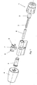
- FIG. 1 1 shows a schematic overall view of a locking device according to the invention in a partially disassembled state with a safety device
- Fig. 2 2 shows an enlarged illustration of the safety device in a first embodiment
- Fig. 3 3 shows a detailed illustration of the eddy current element of the first embodiment
- 4a and 4b Views of two variants of the permanent magnet element of the first embodiment
- Fig. 5 an enlarged view of the safety device in a second embodiment.
- Fig. 1 1 denotes a knob, which is freely rotatable via a hollow shaft 2 and a coupling shaft 3 with an electromechanical clutch disc accommodated in a further knob 4.
- the clutch disc itself can be designed in any manner and can be coupled, for example magnetically or mechanically, to a corresponding component, for example the knob 4.
- the actuation shaft is designated 5 and is penetrated by a sliding sleeve 6.
- a locking lug 7 is provided for the actuation of the lock bolt, this locking lug 7 being kept adjusted in the axial direction by corresponding snap rings 8 and being non-rotatably connected to the actuating shaft 5, which itself is again non-rotatably connected to the inside knob 4 or after the coupling has taken place is rotatably connected to the clutch shaft 3.
- the hollow shaft 2 and the coupling shaft 3 connected to it can be freely rotated.
- the coupling shaft 3 extends through the sliding sleeve 6 and rotates inside the same.
- thermal expansion and rubbing can occur, so that the sliding sleeve 6 suddenly stops with the Coupling shaft 3 also rotates.
- the actuating shaft 5 can also be carried along by the sliding sleeve 6, which can lead to actuation of the locking lug 7 in an undesirable manner.
- a safety device is arranged in the knob 4, which is coupled to the rotational movement of the coupling shaft 3 and whose further rotational movement brakes or blocks it from a defined rotational speed.
- the permanent magnet element 9 has at least one permanent magnet and interacts with an eddy current element 10, which is cup-shaped and surrounds the disk-shaped permanent magnet element 9 circumferentially.
- the permanent magnet element 9 and the eddy current element 10 together form an eddy current tachometer, wherein, as in FIG Fig.
- the eddy current element 10 is connected to a retaining element designed as a spring 11, which exerts a restoring moment on the eddy current element 10 as soon as it starts from the position shown in FIG Fig. 3 shown rest position experiences an angular deflection.
- the angular deflection of the eddy current element 10 is directly proportional to the rotational speed of the permanent magnet element 9.
- the angular deflection of the eddy current element 10 is now translated via a suitable gear into a displacement movement of a displaceable element, not shown, so that the displaceable element from a release position into a braking or Blocking position is shifted.
- the displaceable element engages in a recess in the coupling shaft 3 or interacts in another way with the coupling shaft 3 or with a component connected in a rotationally fixed manner in order to exert a braking torque or a blocking effect on the coupling shaft 3 or the knob 1 ,
- Fig. 4a shows a view of the end face of the permanent magnet element 9, the permanent magnet of which has a first magnetic pole (north pole) 15 and a second magnetic pole (south pole) 16, both of which face the eddy current element 10.
- the end face facing the eddy current element 10 is divided into four, two south poles 16 and two north poles 15 being provided, which are arranged alternately in the circumferential direction. Further modifications are conceivable in which the end face is divided into 6, 8, 10 etc. parts.
- FIG. 5 A modified embodiment of the safety device is shown, in which the eddy current tachometer is enclosed by a ferromagnetic housing 12.
- the eddy current element 10 is also made of a ferromagnetic material.
- a permanent magnet is arranged on the permanent magnet element 9 such that one magnetic pole 13 of the permanent magnet faces the eddy current element 10 and the other magnetic pole 14 of the permanent magnet faces away from the eddy current element 10. This closes a magnetic circuit via the housing 12.
- the invention is not restricted to certain designs of locking devices.
- the security device according to the invention can be used not only in cylinder locks, but also, for example, in fittings which have the function of coupling or uncoupling the handle from the door latch actuation.
- the handle e.g. a handle without effect
- the safety device according to the invention is used and is intended to prevent a jerky actuation of the handle without access authorization from actuating the latch.
Description
Die Erfindung betrifft eine Sicherheitseinrichtung für Schlösser mit einer Handhabe, welche im Ruhezustand frei drehbar und im Betätigungszustand mit dem Verriegelungsglied des Schlosses kuppelbar ist, wobei eine Brems- oder Blockiereinrichtung vorgesehen ist, die ab einer definierten Anzahl von Umdrehungen der Handhabe in einer Zeiteinheit die weitere Drehbewegung bremst oder blockiert.The invention relates to a security device for locks with a handle, which is freely rotatable in the idle state and can be coupled to the locking member of the lock in the actuated state, a braking or blocking device being provided which, from a defined number of revolutions of the handle in a unit time, the further Rotational movement brakes or blocks.
Konventionelle Schlösser können mittels eines Schlüssels betätigt werden, wobei durch Verdrehen eines Schlüssels in einem Schloss eine entsprechende Verriegelungsnase verdreht wird, welche einen Riegel in eine Schließposition verschiebt oder aus einer Schließposition in eine Offenposition zurückzieht. Bei elektronischen Sicherheitssystemen treten anstelle des Schlüssels eine Erkennungslogik und ein elektronischer Schlüssel in Form von Karten oder anderen Identifikationsmedien. Nach einem Lesen des elektronischen Schlüssels, was dem mechanischen Abtasten eines konventionellen Schlüssels entspricht, wird die Drehbewegung einer Handhabe, wie z.B. eines Knaufes oder Griffes, über eine entsprechende Kupplung mit einem weiteren drehbar gelagerten Teil drehfest gekuppelt, welcher in der Folge den Riegel betätigt. In diesem Zusammenhang sind elektronische Sicherheitssysteme bekannt geworden, welche als Doppelknaufzylinder ausgebildet sind, wobei an einer Seite der zu öffnenden Tür Elemente einer Erkennungslogik, und insbesondere Antennen oder dgl., angeordnet sind, wohingegen die Kupplung der Drehbewegung dieses außen liegenden drehbaren Teils nach Erkennen des korrekten Schlüssels über eine Elektronik zumeist auf elektrischem Weg durch Einkuppeln eines Kuppelglieds vorgenommen wird. Bei derartigen Einrichtungen ist ohne eine derartige Kupplung die außen liegende Handhabe frei drehbar. Diese frei drehbare Handhabe ist über eine Welle mit der gegenüberliegenden Seite der Türe oder des Fensters verbunden, an welcher die Kupplung mit dem Betätigungsglied des Schlosses vorgenommen wird. Die Welle wird hierbei mit relativ geringem Spiel durch das Schloss hindurchgeführt, wobei die freie Drehbarkeit bei gleichzeitig relativ geringem Spiel ohne die Gefahr eines Klemmens und ohne die Gefahr einer unbeabsichtigten Kupplung gewährleistet sein muss. Eine mögliche Ausbildung ist beispielsweise der
Bedingt durch die geringen Toleranzen bei der Fertigung derartiger Sicherheitseinrichtungen hat sich aber nun gezeigt, dass eine mögliche missbräuchliche Manipulation dadurch geschaffen wird, dass an die frei drehbare Handhabe ein entsprechendes Antriebsaggregat, beispielsweise ein elektrischer Motor oder Federwerksmotor, angeschlossen wird, welches die Handhabe in rasche Rotation versetzt. Bei einer derartigen raschen Rotation wird eine entsprechende Reibungswärme im Inneren des Schlosses generiert, welche bei Ausdehnung der üblicher Weise frei durchdrehenden Welle zu einem Verreiben oder aber einem unbeabsichtigten Kuppeln einer Außenwelle mit einer Innenwelle führen kann, sodass auf diese Weise trotz fehlender elektronischer Freigabe der Kupplung auf mechanischem Weg eine durch thermische Ausdehnung oder Verreiben erzielte Kupplung zwischen der üblicher Weise frei drehbaren Handhabe und dem Sperrbart entsteht, wodurch das Schloss betätigt werden kann. Eine derartige Fehlbedienung bzw. Sabotagebedienung setzt allerdings voraus, dass die frei drehbare Handhabe über eine Mindestzeit auf eine entsprechende Mindestdrehzahl gebracht werden kann, welche zu einer thermischen Ausdehnung bzw. zum Verreiben führen kann.Due to the small tolerances in the manufacture of such safety devices, it has now been shown that a possible improper manipulation is created by connecting a corresponding drive unit, for example an electric motor or spring motor, to the freely rotatable handle, which quickly handles the handle Rotation offset. With such a rapid rotation, a corresponding frictional heat is generated inside the lock, which, when the shaft rotates freely, can lead to rubbing or an unintentional coupling of an outer shaft with an inner shaft, so that despite the lack of electronic release of the clutch mechanically, a coupling achieved by thermal expansion or rubbing is created between the usual freely rotatable handle and the locking bit, whereby the lock can be operated. Such incorrect operation or sabotage operation, however, presupposes that the freely rotatable handle is limited to a minimum time appropriate minimum speed can be brought, which can lead to thermal expansion or rubbing.
Um eine derartige Sabotage- bzw. Fehlbedienung auszuschließen und gleichzeitig zu gewährleisten, dass die frei drehbare Handhabe nur mit einer relativ geringen Drehgeschwindigkeit frei drehbar bleibt und in anderen Fällen einem Verreiben oder Verklemmen entgegenwirkt, ist in der
Bei einer Sicherheitsvorrichtung des in der
Die Erfindung zielt daher darauf ab, eine Sicherheitseinrichtung der eingangs genannten Art dahingehend zu verbessern, dass die Funktionsfähigkeit auch bei sehr hohen Umdrehungsgeschwindigkeiten und bei hohen Drehmomenten, die auf die Handhabe aufgebracht werden, gewährleistet ist. Die Sicherheitseinrichtung soll weitestgehend unabhängig von den von außen auf das Schloss einwirkenden Kräften funktionieren.The invention therefore aims to improve a safety device of the type mentioned at the outset in such a way that the functionality is ensured even at very high rotational speeds and at high torques which are applied to the handle. The security device should function largely independently of the external forces acting on the lock.
Zur Lösung dieser Aufgabe sieht die Erfindung bei einer Sicherheitseinrichtung der eingangs genannten Art vor, dass die Brems- oder Blockiereinrichtung als Wirbelstrombremse ausgebildet ist. Die Wirbelstrombremse weist hierbei insbesondere ein Magnetelement und ein Wirbelstromelement auf, wobei das Magnetelement entweder wenigstens einen Permanentmagneten aufweist oder einen Elektromagneten, der bei Überschreiten einer bestimmten Drehzahl der Handhabe eingeschaltet wird, wodurch die Wirbelstrombremse ein dem Drehmoment der Handhabe entgegengesetztes Drehmoment aufbringt.To achieve this object, the invention provides in a safety device of the type mentioned at the outset that the braking or blocking device is designed as an eddy current brake. The eddy current brake here has in particular a magnetic element and an eddy current element, the magnetic element either having at least one permanent magnet or an electromagnet which is switched on when a certain speed of the handle is exceeded, as a result of which the eddy current brake applies a torque which is opposite to the torque of the handle.
Das Risiko der eingangs beschriebenen Sabotage- oder Fehlbedienung besteht insbesondere bei Schlössern, bei denen die Handhabe drehfest mit einer das Schloss durchsetzenden Kupplungswelle verbunden ist, die über eine Kupplung mit einer Betätigungswelle kuppelbar ist, die drehfest mit dem Verriegelungsglied des Schlosses verbunden ist, wobei die Betätigungswelle als Hohlwelle ausgebildet ist, welche von der Kupplungswelle durchsetzt ist.The risk of tampering or incorrect operation described at the outset exists in particular in locks in which the handle is connected in a rotationally fixed manner to a coupling shaft passing through the lock, which can be coupled via a coupling to an actuating shaft which is connected in a rotationally fixed manner to the locking member of the lock, the Actuating shaft is designed as a hollow shaft, which is penetrated by the coupling shaft.
Bei einer nicht beanspruchten Ausführung ist bei einer Sicherheitseinrichtung der eingangs genannten Art, wobei die Brems- oder Blockiereinrichtung ein zwischen einer Freigabeposition und einer Brems- oder Blockierposition verlagerbares Element umfasst, das in der Brems- oder Blockierposition mit einem Gegenelement zusammenwirkt, um die weitere Drehbewegung zu bremsen oder zu blockieren, vorgesehen, dass die Handhabe von dem verlagerbaren Element in dessen Freigabeposition mechanisch entkoppelt ist. Die mechanische Entkoppelung stellt sicher, dass von außen auf die Handhabe und die mit der Handhabe ggf. verbundene Welle einwirkenden Kräfte nicht auf den für die Aufbringung des Bremsmoments oder die Blockierung verantwortlichen Teil, nämlich auf das verlagerbare Element der Brems- oder Blockiereinrichtung übertragen werden können. Eine Manipulation oder Beschädigung durch Gewalteinwirkung ist somit ausgeschlossen. Das verlagerbare Element ist insbesondere in der Freigabeposition somit baulich von der Handhabe oder einem mit der Handhabe drehfest verbundenen Element getrennt und dreht sich insbesondere nicht mit der Handhabe mit. Entsprechend einer bevorzugten Weiterbildung wirkt das verlagerbare Element erst in der Brems- oder Blockierposition mit der Handhabe oder einem mit der Handhabe drehfest gekoppelten Teil zusammen, um die weitere Drehbewegung zu bremsen oder zu blockieren.In a non-claimed embodiment, a safety device of the type mentioned at the outset, the braking or blocking device comprising an element which can be displaced between a release position and a braking or blocking position and which, in the braking or blocking position, interacts with a counter-element in order to further rotate to brake or block, it is provided that the handle is mechanically decoupled from the displaceable element in its release position. The mechanical decoupling ensures that external forces acting on the handle and the shaft possibly connected to the handle do not affect the part responsible for applying the braking torque or blocking, namely the displaceable element of the braking or blocking device can be transferred. Manipulation or damage due to violence is therefore excluded. The displaceable element is thus structurally separated from the handle or an element connected in a rotationally fixed manner to the handle, in particular in the release position, and in particular does not rotate with the handle. According to a preferred development, the displaceable element interacts only in the braking or blocking position with the handle or with a part that is coupled in a rotationally fixed manner to the handle in order to brake or block the further rotary movement.
Diese Sicherheitseinrichtung umfasst Ausführungen, bei denen die Erfassungseinrichtung zum Erfassen der Drehgeschwindigkeit der Handhabe von der Brems- bzw. Blockiereinrichtung verschieden ist, insbesondere mechanisch entkoppelt ist. Damit unterliegt die Brems- bzw. Blockiereinrichtung anders als bei der im Stand der Technik beschriebenen Fliehgewichtbremse nicht den geometrischen und materialmäßigen Beschränkungen der Drehmomenterfassungseinrichtung und kann daher stabiler konstruiert werden.This safety device includes versions in which the detection device for detecting the rotational speed of the handle is different from the braking or blocking device, in particular is mechanically decoupled. In contrast to the centrifugal weight brake described in the prior art, the braking or blocking device is therefore not subject to the geometric and material restrictions of the torque detection device and can therefore be designed to be more stable.
Die mechanische Entkopplung der Drehbewegung der Handhabe von dem verlagerbaren Element wird bevorzugt dadurch erreicht, dass ein Antrieb zum Verlagern des verlagerbaren Elements zwischen der Freigabeposition und der Brems- oder Blockierposition vorgesehen ist, der durch berührungslose, insbesondere magnetische Kopplung mit der Drehbewegung der Handhabe in Bewegung versetzbar ist. Die berührungslose Kopplung ist bevorzugt von einer von der Drehbewegung der Handhabe angetriebenen Wirbelstromkupplung gebildet.The mechanical decoupling of the rotary movement of the handle from the displaceable element is preferably achieved in that a drive for displacing the displaceable element between the release position and the braking or blocking position is provided, which is in motion by contactless, in particular magnetic coupling with the rotary movement of the handle is relocatable. The contactless coupling is preferably formed by an eddy current coupling driven by the rotary movement of the handle.
Alternativ kann die berührungslose Kopplung einen elektrischen Generator umfassen, der von der Drehbewegung der Handhabe angetrieben wird und der eine elektrische Spannung für den Antrieb des verlagerbaren Elements zur Verfügung stellt.Alternatively, the contactless coupling can comprise an electrical generator which is driven by the rotary movement of the handle and which provides an electrical voltage for driving the displaceable element.
Besonders bevorzugt ist die Wirbelstromkupplung nach Art eines Wirbelstromtachometers ausgebildet. Die Wirbelstromkupplung umfasst hierbei bevorzugt ein Wirbelstromelement und ein Permanentmagnetelement, die relativ zueinander drehbar sind. Bei einem Wirbelstromtachometer dreht sich das mit einem Permanentmagneten versehene Permanentmagnetelement und erzeugt in dem in Abstand davon angebrachten Wirbelstromelement Wirbelströme. Das Wirbelstromelement besteht bevorzugt aus einer Metallscheibe oder Glocke aus einem elektrisch leitenden Material, insbesondere Aluminium. Auf Grund der Wirbelströme im Wirbelstromelement entsteht eine zusätzliche Feldenergie. Diese Feldenergie würde vermieden werden, wenn das drehbar gelagerte Wirbelstromelement mitrotieren würde. Daran wird es aber durch ein Rückstellelement gehindert. Das Magnetfeld steigt linear mit der Geschwindigkeit, die Feldenergie quadratisch, die Kraftwirkung als deren Ableitung wieder linear, ebenso wie die Rückstellkraft des Rückstellelements mit seiner Winkelauslenkung. Damit ist die Auslenkung bzw. der Drehwinkel des Wirbelstromelements proportional zur Drehzahl. Das Rückstellelement kann hierbei bevorzugt als Federelement ausgebildet sein. Alternativ kann als Rückstellelement jedes andere zur Aufnahme eines Drehmoments oder einer Kraft geeignete Element verwendet werden. Beispielsweise könnte die Abstoßung zweier gleich gepolter Magneten als Widerstand gegen die Winkelauslenkung genutzt werden.The eddy current coupling is particularly preferably designed in the manner of an eddy current tachometer. The eddy current clutch here preferably comprises an eddy current element and a permanent magnet element, which can be rotated relative to one another. In the case of an eddy current tachometer, the permanent magnet element provided with a permanent magnet rotates and generates eddy currents in the eddy current element which is arranged at a distance therefrom. The eddy current element preferably consists of a metal disc or bell made of an electrically conductive material, in particular aluminum. Due to the eddy currents in the eddy current element, an additional field energy is created. This field energy would be avoided if the rotatably mounted eddy current element were also rotated. This is prevented by a reset element. The magnetic field increases linearly with the speed, the field energy increases quadratically, the force effect as its derivation is linear again, as does the restoring force of the restoring element with its angular deflection. The deflection or the angle of rotation of the eddy current element is therefore proportional to the speed. The restoring element can preferably be designed as a spring element. Alternatively, any other element suitable for absorbing a torque or a force can be used as the restoring element. For example, the repulsion of two magnets with the same polarity could be used as resistance to the angular deflection.
Bei der oben beschriebenen Ausbildung des Wirbelstromtachometers ist das Permanentmagnetelement mit der Drehbewegung der Handhabe gekoppelt und von dieser somit angetrieben. Alternativ kann der Wirbelstromtachometer aber auch so ausgebildet sein, dass das Wirbelstromelement mit der Drehbewegung der Handhabe gekoppelt ist. Diesfalls ist nicht das Wirbelstromelement, sondern das drehbar gelagerte Permanentmagnetelement mit dem Rückstellelement verbunden.In the construction of the eddy current tachometer described above, the permanent magnet element is coupled to the rotary movement of the handle and is thus driven by it. Alternatively, the eddy current tachometer can also be designed such that the eddy current element rotates with the handle is coupled. In this case, it is not the eddy current element, but the rotatably mounted permanent magnet element that is connected to the restoring element.
Die Winkelauslenkung des mit dem Rückstellelement verbundenen Teils des Wirbelstromtachometers wird bevorzugt über ein Getriebe oder eine Umsetzeinheit in eine Verlagerungsbewegung des verlagerbaren Elements übersetzt, sodass das verlagerbare Element aus der Freigabeposition in die Brems- oder Blockierposition verlagert wird. Bevorzugt ist die Ausbildung hierbei so getroffen, dass das Getriebe oder die Umsetzeinheit das verlagerbare Element unabhängig von der Drehrichtung der Handhabe aus der Freigabeposition in die Brems- oder Blockierposition verlagern kann.The angular deflection of the part of the eddy current tachometer connected to the restoring element is preferably translated via a gear or a conversion unit into a displacement movement of the displaceable element, so that the displaceable element is displaced from the release position into the braking or blocking position. In this case, the design is preferably such that the transmission or the conversion unit can shift the displaceable element from the release position into the braking or blocking position, regardless of the direction of rotation of the handle.
Das Getriebe oder das Umsetzelement umfasst beispielsweise eine an dem mit dem Rückstellelement verbundenen Teil des Wirbelstromtachometers ausgebildete Rampe, welche die Winkelauslenkung dieses Teils in eine axiale und/oder radiale Bewegung des verlagerbaren Elements umsetzt. Das verlagerbare Element kann hierbei in axialer und/oder radialer Richtung geführt sein und axial und/oder radial mit einem mit der Handhabe drehfest verbundenen Teil des Schlosses in Eingriff gelangen und dadurch die weitere Drehbewegung der Handhabe blockieren.The transmission or the conversion element comprises, for example, a ramp formed on the part of the eddy current tachometer connected to the restoring element, which converts the angular deflection of this part into an axial and / or radial movement of the displaceable element. The displaceable element can in this case be guided in the axial and / or radial direction and can engage axially and / or radially with a part of the lock connected in a rotationally fixed manner to the handle and thereby block the further rotational movement of the handle.
Eine bevorzugte Ausbildung sieht vor, dass das Wirbelstromelement als Wirbelstromscheibe aus ferromagnetischem Material ausgebildet ist. Unter gewissen Umständen kann die Verwendung eines ferromagnetischen Materials zu einer Verstärkung der Wirbelströme führen.A preferred embodiment provides that the eddy current element is designed as an eddy current disk made of ferromagnetic material. In certain circumstances, the use of a ferromagnetic material can increase the eddy currents.
Bei einer Wirbelstromkupplung bzw. einem Wirbelstromtachometer ist in der Regel wenigstens ein Permanentmagnet an dem Permanentmagnetelement so angeordnet, dass sowohl der eine Pol als auch der andere Pol des Magneten dem Wirbelstromelement zugewandt ist. Eine bevorzugte Ausbildung sieht alternativ aber vor, dass das Permanentmagnetelement einen ersten Pol und einen zweiten Pol aufweist, wobei der erste Pol dem Wirbelstromelement zugewandt ist und der zweite Pol dem Wirbelstromelement abgewandt ist. Bei einer derartigen Ausführung kann sich ein Magnetkreis quer durch das Wirbelstromelement schließen. Dies wird gemäß einer bevorzugen Ausführungsvariante noch dadurch begünstigt, dass die Wirbelstromkupplung ein metallisches, vorzugsweise ferromagnetisches Gehäuse aufweist, das mit dem ersten und dem zweiten Pol des Permanentmagnetelements einen geschlossenen Magnetkreis ausbildet.In the case of an eddy current clutch or an eddy current tachometer, there is generally at least one permanent magnet on the permanent magnet element so arranged that both the one pole and the other pole of the magnet face the eddy current element. A preferred embodiment alternatively provides that the permanent magnet element has a first pole and a second pole, the first pole facing the eddy current element and the second pole facing away from the eddy current element. In such an embodiment, a magnetic circuit can close across the eddy current element. According to a preferred embodiment variant, this is further favored in that the eddy current clutch has a metallic, preferably ferromagnetic housing which forms a closed magnetic circuit with the first and the second pole of the permanent magnet element.
Die Erfindung wird nachfolgend anhand von in der Zeichnung schematisch dargestellten Ausführungsbeispielen näher erläutert. In dieser zeigen
In
Ohne eine entsprechende Kupplung der Betätigungswelle 5 mit dem Knauf 1 kann die Hohlwelle 2 und die damit verbundene Kupplungswelle 3 frei verdreht werden. Die Kupplungswelle 3 erstreckt sich hierbei durch die Gleithülse 6 hindurch und dreht sich im Inneren derselben. Bei einer Sabotage, bei welcher der Knauf 1 und damit die Kupplungswelle 3 mit einem hohen Drehmoment beaufschlagt und in Rotation mit Drehgeschwindigkeiten von 5.000 - 20.000 U/min versetzt wird, kann es zu thermischen Ausdehnungen und Verreibungen kommen, sodass die Gleithülse 6 plötzlich mit der Kupplungswelle 3 mitrotiert. In weiterer Folge kann auf Grund desselben Effektes auch die Betätigungswelle 5 von der Gleithülse 6 mitgenommen werden, was in unerwünschter Weise zu einer Betätigung der Sperrnase 7 führen kann.Without a corresponding coupling of the actuating
Um die oben beschriebene unerwünschte Betätigung der Sperrnase 7 zu vermeiden, ist im Knauf 4 eine Sicherheitseinrichtung angeordnet, welche mit der Drehbewegung der Kupplungswelle 3 gekoppelt ist und deren weitere Drehbewegung ab einer definierten Umdrehungsgeschwindigkeit bremst oder blockiert. Die Sicherheitseinrichtung umfasst bei dem in
In
Grundsätzlich ist die Erfindung nicht auf bestimmte Ausführungen von Verriegelungseinrichtungen beschränkt. So kann die erfindungsgemäße Sicherheitseinrichtung nicht nur bei Zylinderschlössern zum Einsatz gelangen, sondern beispielsweise auch in Beschlägen, welche die Funktion haben, die Handhabe mit der Türfallenbetätigung zu koppeln oder zu entkoppeln. Im entkoppelten Zustand ist die Handhabe, wie z.B. ein Drücker ohne Wirkung, während die Handhabe im gekoppelten Zustand die Falle betätigt. Im entkoppelten Zustand kommt die erfindungsgemäße Sicherheitseinrichtung zum Einsatz und soll verhindern, dass eine ruckartige Betätigung der Handhabe ohne Zutrittsberechtigung zu einer Betätigung der Falle führt.In principle, the invention is not restricted to certain designs of locking devices. Thus, the security device according to the invention can be used not only in cylinder locks, but also, for example, in fittings which have the function of coupling or uncoupling the handle from the door latch actuation. In the decoupled state, the handle, e.g. a handle without effect, while the handle operates the latch when coupled. In the uncoupled state, the safety device according to the invention is used and is intended to prevent a jerky actuation of the handle without access authorization from actuating the latch.
Claims (3)
- Security device for locks with a handle, which can be freely rotated in the idle state and can be coupled to the locking member (7) of the lock in the actuated state, wherein a braking or blocking device is provided, which, starting from a defined number of revolutions of the handle per time unit, brakes or blocks the further rotary movement, characterized in that the braking or blocking device is designed as an eddy current brake.
- Security device according to claim 1, characterized in that the handle (1) is connected in a rotationally fixed manner to a coupling shaft (3) penetrating the lock, which can be coupled via a coupling to an actuating shaft (5), which is connected in a rotationally fixed manner to the locking member (7) of the lock, wherein the actuating shaft (5) is designed as a hollow shaft, which is penetrated by the coupling shaft (3).
- Locking device for building doors, preferably lock cylinder or fitting, window or the like, comprising a handle, which can be freely rotated in the idle state and can be coupled to the locking member of the locking device in the actuating state, characterized by a security device according to any one of claims 1 or 2.
Applications Claiming Priority (2)
| Application Number | Priority Date | Filing Date | Title |
|---|---|---|---|
| ATA560/2012A AT512658B1 (en) | 2012-05-10 | 2012-05-10 | Safety device for locks |
| EP13450018.0A EP2662514B1 (en) | 2012-05-10 | 2013-04-25 | Safety mechanism for locks |
Related Parent Applications (2)
| Application Number | Title | Priority Date | Filing Date |
|---|---|---|---|
| EP13450018.0A Division-Into EP2662514B1 (en) | 2012-05-10 | 2013-04-25 | Safety mechanism for locks |
| EP13450018.0A Division EP2662514B1 (en) | 2012-05-10 | 2013-04-25 | Safety mechanism for locks |
Publications (2)
| Publication Number | Publication Date |
|---|---|
| EP3404172A1 EP3404172A1 (en) | 2018-11-21 |
| EP3404172B1 true EP3404172B1 (en) | 2020-02-26 |
Family
ID=48326231
Family Applications (2)
| Application Number | Title | Priority Date | Filing Date |
|---|---|---|---|
| EP18000496.2A Active EP3404172B1 (en) | 2012-05-10 | 2013-04-25 | Safety mechanism for locks |
| EP13450018.0A Not-in-force EP2662514B1 (en) | 2012-05-10 | 2013-04-25 | Safety mechanism for locks |
Family Applications After (1)
| Application Number | Title | Priority Date | Filing Date |
|---|---|---|---|
| EP13450018.0A Not-in-force EP2662514B1 (en) | 2012-05-10 | 2013-04-25 | Safety mechanism for locks |
Country Status (3)
| Country | Link |
|---|---|
| EP (2) | EP3404172B1 (en) |
| AT (1) | AT512658B1 (en) |
| ES (2) | ES2737732T3 (en) |
Families Citing this family (4)
| Publication number | Priority date | Publication date | Assignee | Title |
|---|---|---|---|---|
| AT514596B1 (en) * | 2013-06-18 | 2015-02-15 | Evva Sicherheitstechnologie | Safety device for locking device |
| CN106285205B (en) * | 2016-05-30 | 2018-06-05 | 南京巨量数据技术有限公司 | One kind can encrypt lock core structure and its application |
| CN106652143B (en) * | 2017-02-20 | 2020-10-02 | 荆其林 | Anti-theft lock and carrier device |
| CN112012581B (en) * | 2020-09-18 | 2024-02-09 | 广东好太太智能家居有限公司 | Lock locking system |
Family Cites Families (5)
| Publication number | Priority date | Publication date | Assignee | Title |
|---|---|---|---|---|
| DE19601424A1 (en) * | 1996-01-17 | 1997-07-24 | Fliether Karl Gmbh & Co | Drive device for a lock, a lock cylinder or the like |
| DE19851308C2 (en) | 1997-11-07 | 2002-11-07 | Simons & Voss Identifikationss | lock cylinder |
| DE19848286B4 (en) * | 1998-10-20 | 2009-10-08 | Uhlmann, Günter | Coupling assembly for an electromechanical locking system |
| DE102005040161A1 (en) * | 2005-08-25 | 2007-03-01 | Cestronics Gmbh | Lock cylinder with centrifugal brake |
| AT501753B1 (en) * | 2006-02-22 | 2006-11-15 | Evva Werke | SAFETY DEVICE FOR LOCKS |
-
2012
- 2012-05-10 AT ATA560/2012A patent/AT512658B1/en not_active IP Right Cessation
-
2013
- 2013-04-25 ES ES13450018T patent/ES2737732T3/en active Active
- 2013-04-25 EP EP18000496.2A patent/EP3404172B1/en active Active
- 2013-04-25 EP EP13450018.0A patent/EP2662514B1/en not_active Not-in-force
- 2013-04-25 ES ES18000496T patent/ES2792094T3/en active Active
Non-Patent Citations (1)
| Title |
|---|
| None * |
Also Published As
| Publication number | Publication date |
|---|---|
| EP2662514A3 (en) | 2017-11-29 |
| AT512658A4 (en) | 2013-10-15 |
| EP2662514A2 (en) | 2013-11-13 |
| EP2662514B1 (en) | 2019-04-24 |
| AT512658B1 (en) | 2013-10-15 |
| ES2792094T3 (en) | 2020-11-10 |
| ES2737732T3 (en) | 2020-01-15 |
| EP3404172A1 (en) | 2018-11-21 |
Similar Documents
| Publication | Publication Date | Title |
|---|---|---|
| EP1987218B1 (en) | Lock with safety system | |
| EP2473690B1 (en) | Closing device | |
| EP3404172B1 (en) | Safety mechanism for locks | |
| DE3632904C2 (en) | ||
| EP1736620A1 (en) | Lock cylinder with locked knob shaft | |
| DE102014108365A1 (en) | Locking device, in particular lock | |
| EP2816180B1 (en) | Safety device for locking device | |
| WO2012062548A1 (en) | Steering device for a motor vehicle and method for locking a steering device | |
| EP2821568B1 (en) | Locking device, particularly lock cylinder | |
| DE102007011554A1 (en) | Clutch arrangement for electronic lock cylinders, is in lock cylinder between two shafts, where control element is displaced between blocking position and release position and shifted in swiveling manner around axle by actuating element | |
| EP1931843B1 (en) | Locking device | |
| EP2985398B1 (en) | Lock-cylinder assembly | |
| DE112007002578B4 (en) | lock cylinder | |
| EP2818611B1 (en) | Locking cylinder with a safety device | |
| WO2007022910A2 (en) | Unlocking and locking element | |
| DE102019100757B4 (en) | Locking device and locking system | |
| EP3412851B1 (en) | Spindle hole assembly for a lock | |
| EP3392094B1 (en) | Device for locking and unlocking an essential component of a motor vehicle | |
| DE102013103047A1 (en) | coupling device | |
| DE10207649B4 (en) | Electrically controlled lock |
Legal Events
| Date | Code | Title | Description |
|---|---|---|---|
| PUAI | Public reference made under article 153(3) epc to a published international application that has entered the european phase |
Free format text: ORIGINAL CODE: 0009012 |
|
| STAA | Information on the status of an ep patent application or granted ep patent |
Free format text: STATUS: THE APPLICATION HAS BEEN PUBLISHED |
|
| AC | Divisional application: reference to earlier application |
Ref document number: 2662514 Country of ref document: EP Kind code of ref document: P |
|
| AK | Designated contracting states |
Kind code of ref document: A1 Designated state(s): AL AT BE BG CH CY CZ DE DK EE ES FI FR GB GR HR HU IE IS IT LI LT LU LV MC MK MT NL NO PL PT RO RS SE SI SK SM TR |
|
| AX | Request for extension of the european patent |
Extension state: BA ME |
|
| STAA | Information on the status of an ep patent application or granted ep patent |
Free format text: STATUS: REQUEST FOR EXAMINATION WAS MADE |
|
| 17P | Request for examination filed |
Effective date: 20190514 |
|
| RBV | Designated contracting states (corrected) |
Designated state(s): AL AT BE BG CH CY CZ DE DK EE ES FI FR GB GR HR HU IE IS IT LI LT LU LV MC MK MT NL NO PL PT RO RS SE SI SK SM TR |
|
| GRAP | Despatch of communication of intention to grant a patent |
Free format text: ORIGINAL CODE: EPIDOSNIGR1 |
|
| STAA | Information on the status of an ep patent application or granted ep patent |
Free format text: STATUS: GRANT OF PATENT IS INTENDED |
|
| RIC1 | Information provided on ipc code assigned before grant |
Ipc: E05B 47/00 20060101ALN20190917BHEP Ipc: E05B 47/06 20060101ALI20190917BHEP Ipc: E05B 17/20 20060101ALI20190917BHEP Ipc: E05B 13/00 20060101AFI20190917BHEP Ipc: E05B 9/04 20060101ALI20190917BHEP |
|
| INTG | Intention to grant announced |
Effective date: 20191018 |
|
| GRAS | Grant fee paid |
Free format text: ORIGINAL CODE: EPIDOSNIGR3 |
|
| GRAA | (expected) grant |
Free format text: ORIGINAL CODE: 0009210 |
|
| STAA | Information on the status of an ep patent application or granted ep patent |
Free format text: STATUS: THE PATENT HAS BEEN GRANTED |
|
| AC | Divisional application: reference to earlier application |
Ref document number: 2662514 Country of ref document: EP Kind code of ref document: P |
|
| AK | Designated contracting states |
Kind code of ref document: B1 Designated state(s): AL AT BE BG CH CY CZ DE DK EE ES FI FR GB GR HR HU IE IS IT LI LT LU LV MC MK MT NL NO PL PT RO RS SE SI SK SM TR |
|
| REG | Reference to a national code |
Ref country code: GB Ref legal event code: FG4D Free format text: NOT ENGLISH |
|
| REG | Reference to a national code |
Ref country code: CH Ref legal event code: EP |
|
| REG | Reference to a national code |
Ref country code: AT Ref legal event code: REF Ref document number: 1237796 Country of ref document: AT Kind code of ref document: T Effective date: 20200315 |
|
| REG | Reference to a national code |
Ref country code: IE Ref legal event code: FG4D Free format text: LANGUAGE OF EP DOCUMENT: GERMAN |
|
| REG | Reference to a national code |
Ref country code: DE Ref legal event code: R096 Ref document number: 502013014362 Country of ref document: DE |
|
| REG | Reference to a national code |
Ref country code: NL Ref legal event code: FP |
|
| REG | Reference to a national code |
Ref country code: SE Ref legal event code: TRGR |
|
| PG25 | Lapsed in a contracting state [announced via postgrant information from national office to epo] |
Ref country code: NO Free format text: LAPSE BECAUSE OF FAILURE TO SUBMIT A TRANSLATION OF THE DESCRIPTION OR TO PAY THE FEE WITHIN THE PRESCRIBED TIME-LIMIT Effective date: 20200526 Ref country code: FI Free format text: LAPSE BECAUSE OF FAILURE TO SUBMIT A TRANSLATION OF THE DESCRIPTION OR TO PAY THE FEE WITHIN THE PRESCRIBED TIME-LIMIT Effective date: 20200226 Ref country code: RS Free format text: LAPSE BECAUSE OF FAILURE TO SUBMIT A TRANSLATION OF THE DESCRIPTION OR TO PAY THE FEE WITHIN THE PRESCRIBED TIME-LIMIT Effective date: 20200226 |
|
| PGFP | Annual fee paid to national office [announced via postgrant information from national office to epo] |
Ref country code: ES Payment date: 20200504 Year of fee payment: 8 Ref country code: DE Payment date: 20200429 Year of fee payment: 8 Ref country code: CH Payment date: 20200504 Year of fee payment: 8 Ref country code: FR Payment date: 20200427 Year of fee payment: 8 Ref country code: NL Payment date: 20200426 Year of fee payment: 8 |
|
| REG | Reference to a national code |
Ref country code: LT Ref legal event code: MG4D |
|
| PG25 | Lapsed in a contracting state [announced via postgrant information from national office to epo] |
Ref country code: IS Free format text: LAPSE BECAUSE OF FAILURE TO SUBMIT A TRANSLATION OF THE DESCRIPTION OR TO PAY THE FEE WITHIN THE PRESCRIBED TIME-LIMIT Effective date: 20200626 Ref country code: HR Free format text: LAPSE BECAUSE OF FAILURE TO SUBMIT A TRANSLATION OF THE DESCRIPTION OR TO PAY THE FEE WITHIN THE PRESCRIBED TIME-LIMIT Effective date: 20200226 Ref country code: GR Free format text: LAPSE BECAUSE OF FAILURE TO SUBMIT A TRANSLATION OF THE DESCRIPTION OR TO PAY THE FEE WITHIN THE PRESCRIBED TIME-LIMIT Effective date: 20200527 Ref country code: LV Free format text: LAPSE BECAUSE OF FAILURE TO SUBMIT A TRANSLATION OF THE DESCRIPTION OR TO PAY THE FEE WITHIN THE PRESCRIBED TIME-LIMIT Effective date: 20200226 Ref country code: BG Free format text: LAPSE BECAUSE OF FAILURE TO SUBMIT A TRANSLATION OF THE DESCRIPTION OR TO PAY THE FEE WITHIN THE PRESCRIBED TIME-LIMIT Effective date: 20200526 |
|
| PGFP | Annual fee paid to national office [announced via postgrant information from national office to epo] |
Ref country code: SE Payment date: 20200429 Year of fee payment: 8 Ref country code: GB Payment date: 20200427 Year of fee payment: 8 |
|
| PG25 | Lapsed in a contracting state [announced via postgrant information from national office to epo] |
Ref country code: LT Free format text: LAPSE BECAUSE OF FAILURE TO SUBMIT A TRANSLATION OF THE DESCRIPTION OR TO PAY THE FEE WITHIN THE PRESCRIBED TIME-LIMIT Effective date: 20200226 Ref country code: EE Free format text: LAPSE BECAUSE OF FAILURE TO SUBMIT A TRANSLATION OF THE DESCRIPTION OR TO PAY THE FEE WITHIN THE PRESCRIBED TIME-LIMIT Effective date: 20200226 Ref country code: PT Free format text: LAPSE BECAUSE OF FAILURE TO SUBMIT A TRANSLATION OF THE DESCRIPTION OR TO PAY THE FEE WITHIN THE PRESCRIBED TIME-LIMIT Effective date: 20200719 Ref country code: SM Free format text: LAPSE BECAUSE OF FAILURE TO SUBMIT A TRANSLATION OF THE DESCRIPTION OR TO PAY THE FEE WITHIN THE PRESCRIBED TIME-LIMIT Effective date: 20200226 Ref country code: DK Free format text: LAPSE BECAUSE OF FAILURE TO SUBMIT A TRANSLATION OF THE DESCRIPTION OR TO PAY THE FEE WITHIN THE PRESCRIBED TIME-LIMIT Effective date: 20200226 Ref country code: RO Free format text: LAPSE BECAUSE OF FAILURE TO SUBMIT A TRANSLATION OF THE DESCRIPTION OR TO PAY THE FEE WITHIN THE PRESCRIBED TIME-LIMIT Effective date: 20200226 Ref country code: CZ Free format text: LAPSE BECAUSE OF FAILURE TO SUBMIT A TRANSLATION OF THE DESCRIPTION OR TO PAY THE FEE WITHIN THE PRESCRIBED TIME-LIMIT Effective date: 20200226 Ref country code: SK Free format text: LAPSE BECAUSE OF FAILURE TO SUBMIT A TRANSLATION OF THE DESCRIPTION OR TO PAY THE FEE WITHIN THE PRESCRIBED TIME-LIMIT Effective date: 20200226 |
|
| REG | Reference to a national code |
Ref country code: CH Ref legal event code: PFUS Owner name: EVVA SICHERHEITSTECHNOLOGIE GMBH, AT Free format text: FORMER OWNER: EVVA SICHERHEITSTECHNOLOGIE GMBH, AT |
|
| REG | Reference to a national code |
Ref country code: ES Ref legal event code: FG2A Ref document number: 2792094 Country of ref document: ES Kind code of ref document: T3 Effective date: 20201110 |
|
| REG | Reference to a national code |
Ref country code: DE Ref legal event code: R097 Ref document number: 502013014362 Country of ref document: DE |
|
| PG25 | Lapsed in a contracting state [announced via postgrant information from national office to epo] |
Ref country code: MC Free format text: LAPSE BECAUSE OF FAILURE TO SUBMIT A TRANSLATION OF THE DESCRIPTION OR TO PAY THE FEE WITHIN THE PRESCRIBED TIME-LIMIT Effective date: 20200226 |
|
| PLBE | No opposition filed within time limit |
Free format text: ORIGINAL CODE: 0009261 |
|
| STAA | Information on the status of an ep patent application or granted ep patent |
Free format text: STATUS: NO OPPOSITION FILED WITHIN TIME LIMIT |
|
| PG25 | Lapsed in a contracting state [announced via postgrant information from national office to epo] |
Ref country code: IT Free format text: LAPSE BECAUSE OF FAILURE TO SUBMIT A TRANSLATION OF THE DESCRIPTION OR TO PAY THE FEE WITHIN THE PRESCRIBED TIME-LIMIT Effective date: 20200226 Ref country code: LU Free format text: LAPSE BECAUSE OF NON-PAYMENT OF DUE FEES Effective date: 20200425 |
|
| 26N | No opposition filed |
Effective date: 20201127 |
|
| REG | Reference to a national code |
Ref country code: BE Ref legal event code: MM Effective date: 20200430 |
|
| PG25 | Lapsed in a contracting state [announced via postgrant information from national office to epo] |
Ref country code: BE Free format text: LAPSE BECAUSE OF NON-PAYMENT OF DUE FEES Effective date: 20200430 Ref country code: PL Free format text: LAPSE BECAUSE OF FAILURE TO SUBMIT A TRANSLATION OF THE DESCRIPTION OR TO PAY THE FEE WITHIN THE PRESCRIBED TIME-LIMIT Effective date: 20200226 Ref country code: SI Free format text: LAPSE BECAUSE OF FAILURE TO SUBMIT A TRANSLATION OF THE DESCRIPTION OR TO PAY THE FEE WITHIN THE PRESCRIBED TIME-LIMIT Effective date: 20200226 |
|
| PG25 | Lapsed in a contracting state [announced via postgrant information from national office to epo] |
Ref country code: IE Free format text: LAPSE BECAUSE OF NON-PAYMENT OF DUE FEES Effective date: 20200425 |
|
| REG | Reference to a national code |
Ref country code: AT Ref legal event code: MM01 Ref document number: 1237796 Country of ref document: AT Kind code of ref document: T Effective date: 20200425 |
|
| PG25 | Lapsed in a contracting state [announced via postgrant information from national office to epo] |
Ref country code: AT Free format text: LAPSE BECAUSE OF NON-PAYMENT OF DUE FEES Effective date: 20200425 |
|
| REG | Reference to a national code |
Ref country code: DE Ref legal event code: R119 Ref document number: 502013014362 Country of ref document: DE |
|
| REG | Reference to a national code |
Ref country code: SE Ref legal event code: EUG |
|
| REG | Reference to a national code |
Ref country code: NL Ref legal event code: MM Effective date: 20210501 |
|
| GBPC | Gb: european patent ceased through non-payment of renewal fee |
Effective date: 20210425 |
|
| PG25 | Lapsed in a contracting state [announced via postgrant information from national office to epo] |
Ref country code: SE Free format text: LAPSE BECAUSE OF NON-PAYMENT OF DUE FEES Effective date: 20210426 Ref country code: FR Free format text: LAPSE BECAUSE OF NON-PAYMENT OF DUE FEES Effective date: 20210430 Ref country code: GB Free format text: LAPSE BECAUSE OF NON-PAYMENT OF DUE FEES Effective date: 20210425 Ref country code: DE Free format text: LAPSE BECAUSE OF NON-PAYMENT OF DUE FEES Effective date: 20211103 Ref country code: CH Free format text: LAPSE BECAUSE OF NON-PAYMENT OF DUE FEES Effective date: 20210430 Ref country code: LI Free format text: LAPSE BECAUSE OF NON-PAYMENT OF DUE FEES Effective date: 20210430 |
|
| PG25 | Lapsed in a contracting state [announced via postgrant information from national office to epo] |
Ref country code: NL Free format text: LAPSE BECAUSE OF NON-PAYMENT OF DUE FEES Effective date: 20210501 |
|
| PG25 | Lapsed in a contracting state [announced via postgrant information from national office to epo] |
Ref country code: TR Free format text: LAPSE BECAUSE OF FAILURE TO SUBMIT A TRANSLATION OF THE DESCRIPTION OR TO PAY THE FEE WITHIN THE PRESCRIBED TIME-LIMIT Effective date: 20200226 Ref country code: MT Free format text: LAPSE BECAUSE OF FAILURE TO SUBMIT A TRANSLATION OF THE DESCRIPTION OR TO PAY THE FEE WITHIN THE PRESCRIBED TIME-LIMIT Effective date: 20200226 Ref country code: CY Free format text: LAPSE BECAUSE OF FAILURE TO SUBMIT A TRANSLATION OF THE DESCRIPTION OR TO PAY THE FEE WITHIN THE PRESCRIBED TIME-LIMIT Effective date: 20200226 |
|
| PG25 | Lapsed in a contracting state [announced via postgrant information from national office to epo] |
Ref country code: MK Free format text: LAPSE BECAUSE OF FAILURE TO SUBMIT A TRANSLATION OF THE DESCRIPTION OR TO PAY THE FEE WITHIN THE PRESCRIBED TIME-LIMIT Effective date: 20200226 Ref country code: AL Free format text: LAPSE BECAUSE OF FAILURE TO SUBMIT A TRANSLATION OF THE DESCRIPTION OR TO PAY THE FEE WITHIN THE PRESCRIBED TIME-LIMIT Effective date: 20200226 |
|
| REG | Reference to a national code |
Ref country code: ES Ref legal event code: FD2A Effective date: 20220801 |
|
| PG25 | Lapsed in a contracting state [announced via postgrant information from national office to epo] |
Ref country code: ES Free format text: LAPSE BECAUSE OF NON-PAYMENT OF DUE FEES Effective date: 20210426 |