EP2088087B1 - Air filling bag with outer film strengthening structure - Google Patents
Air filling bag with outer film strengthening structure Download PDFInfo
- Publication number
- EP2088087B1 EP2088087B1 EP08165253A EP08165253A EP2088087B1 EP 2088087 B1 EP2088087 B1 EP 2088087B1 EP 08165253 A EP08165253 A EP 08165253A EP 08165253 A EP08165253 A EP 08165253A EP 2088087 B1 EP2088087 B1 EP 2088087B1
- Authority
- EP
- European Patent Office
- Prior art keywords
- air
- film
- hot sealing
- film sheet
- strengthening structure
- Prior art date
- Legal status (The legal status is an assumption and is not a legal conclusion. Google has not performed a legal analysis and makes no representation as to the accuracy of the status listed.)
- Ceased
Links
- 238000005728 strengthening Methods 0.000 title claims description 21
- 238000007789 sealing Methods 0.000 claims description 49
- 239000003779 heat-resistant material Substances 0.000 claims description 7
- 239000000463 material Substances 0.000 claims description 3
- 239000004698 Polyethylene Substances 0.000 description 3
- 230000001154 acute effect Effects 0.000 description 3
- 229920000573 polyethylene Polymers 0.000 description 3
- 239000011347 resin Substances 0.000 description 3
- 229920005989 resin Polymers 0.000 description 3
- -1 Polyethylene Polymers 0.000 description 2
- 238000012986 modification Methods 0.000 description 2
- 230000004048 modification Effects 0.000 description 2
- 230000001419 dependent effect Effects 0.000 description 1
- 230000000694 effects Effects 0.000 description 1
- 239000003292 glue Substances 0.000 description 1
- 239000002655 kraft paper Substances 0.000 description 1
- 238000012856 packing Methods 0.000 description 1
Images


Classifications
-
- B—PERFORMING OPERATIONS; TRANSPORTING
- B65—CONVEYING; PACKING; STORING; HANDLING THIN OR FILAMENTARY MATERIAL
- B65D—CONTAINERS FOR STORAGE OR TRANSPORT OF ARTICLES OR MATERIALS, e.g. BAGS, BARRELS, BOTTLES, BOXES, CANS, CARTONS, CRATES, DRUMS, JARS, TANKS, HOPPERS, FORWARDING CONTAINERS; ACCESSORIES, CLOSURES, OR FITTINGS THEREFOR; PACKAGING ELEMENTS; PACKAGES
- B65D31/00—Bags or like containers made of paper and having structural provision for thickness of contents
- B65D31/14—Valve bags, i.e. with valves for filling
- B65D31/145—Valve bags, i.e. with valves for filling the filling port being provided in a flat upper sealing-edge
-
- B—PERFORMING OPERATIONS; TRANSPORTING
- B65—CONVEYING; PACKING; STORING; HANDLING THIN OR FILAMENTARY MATERIAL
- B65D—CONTAINERS FOR STORAGE OR TRANSPORT OF ARTICLES OR MATERIALS, e.g. BAGS, BARRELS, BOTTLES, BOXES, CANS, CARTONS, CRATES, DRUMS, JARS, TANKS, HOPPERS, FORWARDING CONTAINERS; ACCESSORIES, CLOSURES, OR FITTINGS THEREFOR; PACKAGING ELEMENTS; PACKAGES
- B65D81/00—Containers, packaging elements, or packages, for contents presenting particular transport or storage problems, or adapted to be used for non-packaging purposes after removal of contents
- B65D81/02—Containers, packaging elements, or packages, for contents presenting particular transport or storage problems, or adapted to be used for non-packaging purposes after removal of contents specially adapted to protect contents from mechanical damage
- B65D81/05—Containers, packaging elements, or packages, for contents presenting particular transport or storage problems, or adapted to be used for non-packaging purposes after removal of contents specially adapted to protect contents from mechanical damage maintaining contents at spaced relation from package walls, or from other contents
- B65D81/051—Containers, packaging elements, or packages, for contents presenting particular transport or storage problems, or adapted to be used for non-packaging purposes after removal of contents specially adapted to protect contents from mechanical damage maintaining contents at spaced relation from package walls, or from other contents using pillow-like elements filled with cushioning material, e.g. elastic foam, fabric
- B65D81/052—Containers, packaging elements, or packages, for contents presenting particular transport or storage problems, or adapted to be used for non-packaging purposes after removal of contents specially adapted to protect contents from mechanical damage maintaining contents at spaced relation from package walls, or from other contents using pillow-like elements filled with cushioning material, e.g. elastic foam, fabric filled with fluid, e.g. inflatable elements
-
- F—MECHANICAL ENGINEERING; LIGHTING; HEATING; WEAPONS; BLASTING
- F16—ENGINEERING ELEMENTS AND UNITS; GENERAL MEASURES FOR PRODUCING AND MAINTAINING EFFECTIVE FUNCTIONING OF MACHINES OR INSTALLATIONS; THERMAL INSULATION IN GENERAL
- F16K—VALVES; TAPS; COCKS; ACTUATING-FLOATS; DEVICES FOR VENTING OR AERATING
- F16K15/00—Check valves
- F16K15/14—Check valves with flexible valve members
- F16K15/144—Check valves with flexible valve members the closure elements being fixed along all or a part of their periphery
- F16K15/147—Check valves with flexible valve members the closure elements being fixed along all or a part of their periphery the closure elements having specially formed slits or being of an elongated easily collapsible form
Definitions
- the present invention relates to an air filling bag according to the preamble of claim 1, and more particularly to an air filling bag with an outer film strengthening structure.
- cushioning air bags When large-scale articles are placed into a container for transportation, cushioning air bags will be placed in among the articles so as to protect the articles from impact during transportation, to avoid scratches and damage and increase efficiency during transport.
- cushioning air bags are always so large (in order to provide a better cushioning effect), that a lot of time needs to be spent to fill the bag with air; it wastes both time and labor.
- a cushioning air bag is filled with a high pressure gas, the cushioning air bag's check valve is easily broken, and releases the gas; alternatively the outer film of the cushioning air bag is broken and the air leaks out.
- such a cushioning bag is always scratched and damaged by a sharp or acute angle of the article in the container, causing air in the cushioning air bag to leak and lose the cushioning protection. Typically this will not be discovered until the article is removed from the container, and meanwhile the article is scratched or damaged because it lacks a cushioning medium during transport.
- the present invention is proposed to improve the structure of a cushioning air bag, solving the problem that the cushioning air bag is easily scratched and damaged by a sharp or acute angle of an article in a container, causing air to leak and losing the cushioning protection, and further raising the air filling speed to reduce the time required to fill the cushioning air bag with air by improving the structure of the cushioning air bag and its check valve.
- an air filling bag of the present invention includes:
- An air filling bag with an outer film strengthening structure uses first and second films which are independent and not glued to each other, to form an outer film and to strengthen the outer film; air in an air chamber will not leak and article still can be cushioned effectively even if the first film sheet or the second film sheet is broken.
- the main check valve of the air filling bag according to the present invention is formed by stacking two first inner films and two second inner films together, where the two second inner films are stacked between the two first inner films such that high pressure air can be forced into the air chamber to allow the air chamber to be expanded with air, and high pressure during the air filling will not cause the check valve to be broken, thus achieving a reliable air tight seal.
- FIG. 1 is a perspective view, showing an outer film of a bendable multistage cushioning cover bag of a first embodiment according to the present invention
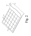
- FIG. 2 is a schematic view, showing the structure of an outer film of a bendable multistage cushioning cover bag of the first embodiment according to the present invention
- FIG. 3A is a plane view, showing a bendable multistage cushioning cover bag of the first embodiment according to the present invention
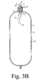
- FIG. 3B is a cross sectional view, showing a bendable multistage cushioning cover bag of the first embodiment according to the present invention
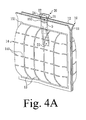
- FIG. 4A is a plane view, showing of a bendable multistage cushioning cover bag of a second embodiment according to the present invention.
- FIG. 4B is a cross sectional view, showing a bendable multistage cushioning cover bag of the second embodiment according to the present invention.
- FIG. 5 is a schematic view, showing the structure of a check valve of a bendable multistage cushioning cover bag of a third embodiment which is not part of the invention.
- FIG. 6 is a perspective view, showing a bendable multistage cushioning cover bag of a fourth embodiment according to the present invention.
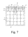
- FIG. 7 is a plane view, showing a bendable multistage cushioning cover bag of the fourth embodiment according to the present invention.
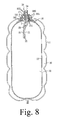
- FIG. 8 is a cross sectional view, showing a bendable multistage cushioning cover bag of the fourth embodiment according to the present invention.
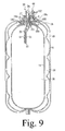
- FIG. 9 is a schematic view, showing the structure of a bendable multistage cushioning cover bag of a fifth embodiment according to the present invention.
- FIG. 1 is a perspective view, showing an outer film of a bendable multistage cushioning cover bag of a first embodiment according to the present invention.
- FIG. 2 is a schematic view, showing the structure of an outer film of a bendable multistage cushioning cover bag of the first embodiment according to the present invention.
- FIG. 3A is a plane view, showing a bendable multistage cushioning cover bag of the first embodiment according to the present invention.
- FIG. 3B is a cross sectional view, showing a bendable multistage cushioning cover bag of the first embodiment according to the present invention.
- An air filling bag with an outer film strengthening structure includes an outer film 10 and a main check valve 20.
- each outer film 10 includes a first film sheet 11 and a second film sheet 12 stacked together, where the first film sheet 11 and the second film sheet 12 may respectively be manufactured from the same material.
- the first film sheet 11 and the second film sheet 12 are respectively manufactured from Polyethylene (PE), or the first film sheet 11 is manufactured from Polyethylene and the second film sheet 12 is manufactured from Kraft paper.
- glue is not spread between the first film sheet 11 and the second film sheet 12, so they are not adhered to each other.
- first film sheet 11 and the second film sheet 12 are adhered to each other by means of hot sealing in a first direction to form a plurality of first hot sealing lines 13, and the first film sheet 11 and the second film sheet 12 are adhered to each other by means of hot sealing in a second direction to form a plurality of second hot sealing lines 14, where the second direction is approximately perpendicular to the first direction in order to allow the first hot sealing lines 13 and the second hot sealing lines 14 to be formed as a beam-to-column connection structure of the outer film 10.
- the first hot sealing line 13 used for adhering the film sheet 11 to the second hot sealing liner 12 be a continuous line, and the second hot sealing line 14 then constituted by a plurality of disconnected hot sealing points 141.
- the present invention is not limited to these.
- the main check valve 20 is positioned between the two sheets of outer film 10. One end of the main check valve 20 projects out of the air chamber 30 formed by adhering the two sheets of outer film 10 to each other. Furthermore, the main check valve 20 includes two sheets of first inner film 21 stacked together, and is placed with two sheets of second inner film 22 stacked together between the two sheets of first inner film 21, where one end of the two sheets of the second inner film 22 projects out of the air chamber 30,aligned with one end of the two sheets of first inner film 22 projecting out of the air chamber 30, or a length of one end of the two sheets of second inner film 22 projecting out of the air chamber 30 is shorter than a length of one end of the two sheets of first inner film 21 projecting out of the air chamber 30.
- a heat resistant material 5 is spread between the two sheets of second inner film 22.
- hot resin or ink is used, and the two sheets of first inner film 21 and the two sheets of second inner film 22 are adhered to each other by a third hot sealing line 151 and a fourth hot sealing line 152 by means of hot sealing.
- the two sheets of second inner film 22 are still not adhered to each other because of the heat resistant material 5 spread between them and a first air inlet 24 is formed.
- a first air passageway 25 connected with the first air inlet 24 is also formed to use to connect the air chamber 30 with the outside.
- the two sheets of first inner film 21 are pulled apart, the two sheets of inner film 22 are forced through the fourth hot sealing line 152, pulling apart to open the first air inlet 24 and allowing outside air to flow into the air chamber 30 via the first air passageway 25. Thereafter, air in the air chamber 30 compresses the first inner film 21 and the second inner film 22 of the main check valve 20, covering the first air passageway 25 and shielding the air chamber 30, preventing the air in the air chamber 30 from leaking, and achieving an air tight seal.
- a top end of the two sheets of first inner film 21 may be longer than the two sheets of second inner film 22 so as to allow a user to pull the two sheets of first inner film 21 apart more easily, without making the mistake of pulling one of the two sheets of first inner film 21 and the adjacent second inner film 22.
- the bottom of the two sheets of first inner film 21 may also longer than the two sheets of second inner film 22, so as to allow the bottoms of the two sheets of first inner film 21 to be attached to each other to cover the first air passageway 25, increasing the effectiveness of air sealing when the air in the air chamber 30 compresses the two sheets of first inner film 21.
- FIG. 4A is a plane view, showing of a bendable multistage cushioning cover bag of a second embodiment according to the present invention.
- FIG. 4B is a cross sectional view, showing a bendable multistage cushioning cover bag of the second embodiment according to the present invention.
- the top ends of the two sheets of the first inner film 21 may be aligned with the top ends of the two sheets of second inner film 22, and the bottom ends of the two sheets of first inner film 21 may then be longer than the two sheets of the second inner film 22.
- the two sheets of second inner film 22 may be pulled apart through the fourth hot sealing line 152, to open the first air inlet 24 when a user pulls the two sheets of first inner film 21 apart outward.
- the bottom ends of the two sheets of first inner film 21 are attached to each other to cover the first air passageway 25, to prevent the air in the air chamber 30 from leaking, and achieving an air tight seal when the air in the air chamber 30 compresses the two sheets of first inner film 21.
- FIG. 5 is a schematic view, showing a structure of a check valve of a bendable multistage cushioning cover bag of a third embodiment which is not part of the invention.
- the main check valve 20 is only placed with two sheets of first inner film 21, where a heat resistant material 5 is spread between the two sheets of first inner film 21.
- a heat resistant material 5 is spread between the two sheets of first inner film 21.
- hot resin or ink is used; the two sheets of first inner film 21 are still not adhered to each other to form a first air inlet 24 and a first air passageway 25 even by means of hot sealing to use for connecting the air chamber 30 with the outside.
- FIG. 6 is a perspective view, showing a bendable multistage cushioning cover bag of a fourth embodiment according to the present invention.
- FIG. 7 is a plane view, showing a bendable multistage cushioning cover bag of the fourth embodiment according to the present invention.
- FIG. 8 is a cross sectional view, showing a bendable multistage cushioning cover bag of the fourth embodiment according to the present invention.
- a plurality of first hot sealing lines 13 separates a space between the first film sheet 11 and the second film sheet 12 into a plurality of air cylinders 16, and a plurality of hot sealing points 141 of the second hot sealing line 14 separates each air cylinder 16 into a plurality of sections 161, where the plurality of sections 161 of each air cylinder 16 are connected with one another.
- An air filling bag with an outer film strengthening structure may further include an air filling passageway 17 and a plurality of auxiliary check valves 18, where the air filling passageway 17 is placed on one end of a plurality of the plurality of air cylinders 16, and it is formed by adhering the first film sheet 11 to the second film sheet 12 by means of hot sealing.
- the auxiliary check valves 18 are positioned between the first film sheet 11 and the second film sheet 12 and include two sheets of auxiliary inner film 180 stacked together; the two sheets of auxiliary inner film 180 are adhered to each other by means of hot sealing to generate a plurality of hot sealing points 18c, thereby adhering the first film sheet 11 to one sheet of auxiliary inner film 180 and the second film sheet 12 to another sheet of auxiliary inner film 180.
- a heat resistant material 5 is spread between the two sheets of auxiliary inner film 180.
- hot resin or ink is used, and the two sheets of auxiliary inner film 180 are still not adhered to each other to form a plurality of second air inlets 181 and a plurality of second air passageways 182 even by means of hot sealing; each second air passageway 182 corresponds to one air cylinder 16, and the plurality of second air inlets 181 and the plurality of second air passageways 182 are used for connecting the air filling passageway 17 with the plurality of air cylinders 16.
- the air inlet 181 After air expands the air filling passageway 17, the first film sheet 11 and the second film sheet 12 are pulled apart to open the second air inlet 181, the air enters each air cylinder 16 via the second air inlet 181 and the second air passageway 182 to cause the plurality of air cylinders 16 to be filled with air and expanded. Thereafter, air in the air cylinder 16 compresses the two sheets of auxiliary inner film 180 of the auxiliary check valve 18 to cover the second air passageway 182, shielding the air cylinder 16 to prevent the air in the air cylinder 16 from leaking, achieving an air tight seal.
- auxiliary inner film 180 of the auxiliary check valve 18 When the aforementioned two sheets of auxiliary inner film 180 of the auxiliary check valve 18 are compressed by the air in the air cylinder 16, they can be side-attached to the first film sheet 11 or the second film sheet 12, or may not be side-attached to the first film sheet 11 or the second film sheet 12, but hung in the air cylinder 16.
- FIG. 9 is a schematic view, showing a structure of a bendable multistage cushioning cover bag of a fifth embodiment according to the present invention.
- an air filling bag with an outer film strengthening structure may further include an outer bag 40 positioned outside the two sheets of outer film 10 and used to cover the air chamber 30 formed by adhering the two sheets of outer film 10 to each other by means of hot sealing.
- the two sheets of outer film 10 can be prevented from being broken by a sharp angle or acute angle of an article in a container by means of the placement of the outer bag 40.
- the outer bag 40 may further be positioned with two sheets of air valve film 480, and a heat resistant material 5 spread between the two sheets of air valve film 480. Part of the two sheets of air valve film 480 spread with the heat resistant material 5 is formed into an air inlet 44 of an outer bag air valve thereby filling the outer bag with air after the two sheets of air valve film 480 are adhered to each other by the third hot sealing line 151 and the fourth hot sealing line 152 by means of hot sealing.
- An air filling bag with an outer film strengthening structure uses a first film sheet and a second film sheet independently and not glued to each other, to constitute an outer film and to strengthen the outer film. If one of the first film sheet and the second film sheet is broken, it will not cause the air in the air chamber to leak and the article will still be cushioned effectively. Moreover, the main check allows high pressure air to be filled into the air chamber, causing the air chamber to be filled with air and expanded, and damage of the main check valve will not result from air tight sealing even if the bag is filled with high pressure air.
Landscapes
- Engineering & Computer Science (AREA)
- Mechanical Engineering (AREA)
- General Engineering & Computer Science (AREA)
- Bag Frames (AREA)
- Buffer Packaging (AREA)
Applications Claiming Priority (1)
| Application Number | Priority Date | Filing Date | Title |
|---|---|---|---|
| TW097104560A TW200934698A (en) | 2008-02-05 | 2008-02-05 | Inflating bag for strengthening outer film structure |
Publications (2)
| Publication Number | Publication Date |
|---|---|
| EP2088087A1 EP2088087A1 (en) | 2009-08-12 |
| EP2088087B1 true EP2088087B1 (en) | 2012-12-26 |
Family
ID=40580900
Family Applications (1)
| Application Number | Title | Priority Date | Filing Date |
|---|---|---|---|
| EP08165253A Ceased EP2088087B1 (en) | 2008-02-05 | 2008-09-26 | Air filling bag with outer film strengthening structure |
Country Status (3)
| Country | Link |
|---|---|
| US (1) | US7913848B2 (enExample) |
| EP (1) | EP2088087B1 (enExample) |
| TW (1) | TW200934698A (enExample) |
Families Citing this family (30)
| Publication number | Priority date | Publication date | Assignee | Title |
|---|---|---|---|---|
| CN101549774B (zh) * | 2008-03-31 | 2013-09-18 | 上海尼禄国际贸易有限公司 | 一种空气包装装置及其生产方法 |
| US9623622B2 (en) * | 2010-02-24 | 2017-04-18 | Michael Baines | Packaging materials and methods |
| WO2011159818A2 (en) * | 2010-06-15 | 2011-12-22 | Russell David D | Self-supporting bladder system for a double wall tank |
| US20120125477A1 (en) * | 2010-11-19 | 2012-05-24 | Cryovac, Inc. | Coiled Valve and Methods of Making and Using the Same |
| CN102008197A (zh) * | 2010-11-26 | 2011-04-13 | 熊平 | 一种具防漏气自锁单向阀的气囊 |
| TWI413608B (zh) * | 2011-06-08 | 2013-11-01 | Yaw Shin Liao | Can be a number of gas filling structure |
| CN202880106U (zh) * | 2012-03-06 | 2013-04-17 | 上海艾尔贝包装科技发展有限公司 | 自粘膜止回阀和空气包装装置 |
| CN102599761B (zh) * | 2012-04-09 | 2014-07-09 | 先驱塑胶电子(惠州)有限公司 | 一种充气产品组合结构 |
| US9725066B2 (en) * | 2013-05-04 | 2017-08-08 | Shanghai Air-Paq Composite Material Co., Ltd | Air bag packaging arrangement and self-adhesive checking valve |
| US10500808B2 (en) | 2014-02-24 | 2019-12-10 | Pregis Innovative Packaging Llc | Inflation and sealing device with release features |
| US20150239633A1 (en) * | 2014-02-25 | 2015-08-27 | Pregis Innovative Packaging Llc | Films with stress relief intra-chamber seals |
| JP6445281B2 (ja) * | 2014-09-01 | 2018-12-26 | 克敏 吉房 | 気体クッション材 |
| CN105151529B (zh) * | 2015-04-23 | 2019-03-08 | 张嘉盈 | 空气包装装置及其充气阀和制造方法 |
| US11402066B2 (en) * | 2015-05-22 | 2022-08-02 | Jiaying Zhang | Inflation method for air cushion body, inflation system of same, and inflation apparatus thereof |
| CN105109825B (zh) * | 2015-09-14 | 2017-10-31 | 江阴艾尔克缓冲材料有限公司 | 气柱式保护装置 |
| CO2017005549A1 (es) * | 2017-06-02 | 2017-08-18 | Velez Juan Manuel Estrada | Válvula para la desgasificación con control de presión positiva, métodos de fabricación de las mismas y empaques que las contienen |
| CN110239834A (zh) * | 2018-03-09 | 2019-09-17 | 上海锦蕊新材料科技有限公司 | 囊中囊包装袋及其制造方法 |
| KR102516885B1 (ko) | 2018-05-10 | 2023-03-30 | 삼성전자주식회사 | 증착 장비 및 이를 이용한 반도체 장치 제조 방법 |
| US11338980B2 (en) | 2018-07-20 | 2022-05-24 | The Procter & Gamble Company | Shaped flexible shipping package and method of making |
| CN108792277A (zh) * | 2018-08-02 | 2018-11-13 | 北京工商大学 | 可变向逆止的自调节缓冲气垫 |
| TWI707810B (zh) * | 2019-11-08 | 2020-10-21 | 亞比斯包材工場股份有限公司 | 密封結構 |
| CN111271252A (zh) * | 2020-02-26 | 2020-06-12 | 陈卫新 | 一种自充排管和应用该充气排管的气泵 |
| US11897682B2 (en) | 2020-03-13 | 2024-02-13 | The Procter & Gamble Company | Flexible package |
| US11858713B2 (en) | 2020-10-30 | 2024-01-02 | The Procter & Gamble Company | Inflation feature for package, inflation rig assembly, and method of inflating |
| US20220219821A1 (en) * | 2021-01-11 | 2022-07-14 | Bell Textron Inc. | Inflatable Aerodynamic Cargo Container |
| CN113086392B (zh) * | 2021-03-26 | 2022-09-06 | 上海唐科新材料科技有限公司 | 一种抗震缓冲气柱袋、气柱膜及气柱袋加工工艺 |
| CN113320831A (zh) * | 2021-05-28 | 2021-08-31 | 曹桂芬 | 一种充气袋及其加工系统与加工方法 |
| CN113479488B (zh) * | 2021-08-03 | 2022-05-24 | 银川市富邦印刷包装有限公司 | 多层隔腔纸壁结构的防挤压纸质包装箱 |
| US12378056B2 (en) | 2021-10-11 | 2025-08-05 | The Procter & Gamble Company | Shaped flexible shipping package and method of making |
| CN114273238B8 (zh) * | 2021-12-31 | 2024-02-20 | 山西峰凡科技物流股份有限公司 | 一种物流包裹全自动分拣设备 |
Family Cites Families (13)
| Publication number | Priority date | Publication date | Assignee | Title |
|---|---|---|---|---|
| US3137438A (en) * | 1961-08-29 | 1964-06-16 | Charles J Milton | Disposable container |
| CA1186659A (en) * | 1982-07-07 | 1985-05-07 | Walter G. Soroka | Inflatable packaging structure |
| US5178281A (en) * | 1992-01-21 | 1993-01-12 | S. P. Chemical Co., Ltd. | Cushioning package |
| US5447235A (en) * | 1994-07-18 | 1995-09-05 | Air Packaging Technologies, Inc. | Bag with squeeze valve and method for packaging an article therein |
| US5772034A (en) * | 1997-07-15 | 1998-06-30 | Lin; Chih-Jen | Bag assembly |
| US5857571A (en) * | 1997-12-01 | 1999-01-12 | Tschantz; Mitchell | Inflatable packaging cushion |
| DK144397A (da) * | 1997-12-11 | 1999-03-22 | Unigreen Int As | Fryseformpose |
| US6283296B1 (en) * | 1998-12-29 | 2001-09-04 | Air Packaging Technologies, Inc. | Quilted inflatable packaging device |
| US7165677B2 (en) * | 2004-08-10 | 2007-01-23 | Air-Paq, Inc. | Structure of air-packing device |
| US20070053615A1 (en) * | 2005-09-02 | 2007-03-08 | I-Wen Liu | Shockproof packing bag |
| US7481252B2 (en) * | 2006-02-10 | 2009-01-27 | Air-Paq, Inc. | Structure of check valve for air-packing device |
| DE202006002935U1 (de) * | 2006-02-23 | 2006-04-20 | Leadpak Industrial Co., Ltd. | Mehrschichtige Membranventilanordnung |
| TW200815249A (en) * | 2006-09-29 | 2008-04-01 | Yao-Sin Liao | Air enclosure with strengthened air-tightness function |
-
2008
- 2008-02-05 TW TW097104560A patent/TW200934698A/zh not_active IP Right Cessation
- 2008-09-16 US US12/211,257 patent/US7913848B2/en not_active Expired - Fee Related
- 2008-09-26 EP EP08165253A patent/EP2088087B1/en not_active Ceased
Also Published As
| Publication number | Publication date |
|---|---|
| EP2088087A1 (en) | 2009-08-12 |
| TW200934698A (en) | 2009-08-16 |
| TWI333476B (enExample) | 2010-11-21 |
| US20090196531A1 (en) | 2009-08-06 |
| US7913848B2 (en) | 2011-03-29 |
Similar Documents
| Publication | Publication Date | Title |
|---|---|---|
| EP2088087B1 (en) | Air filling bag with outer film strengthening structure | |
| US7959003B2 (en) | Air enclosure and check valve thereof capable of being filled with high pressure air | |
| KR101018979B1 (ko) | 다단 구속형 공기밀봉체 | |
| CN105083757B (zh) | 多层式空气包装装置及其制造方法 | |
| US7631762B2 (en) | Hammock-type vibration-absorbing air sheath | |
| US8088459B2 (en) | Air enclosure with independent double layer air chambers | |
| US7665609B2 (en) | Air-tightness strengthening air enclosure | |
| EP1938961B1 (en) | Apparatus and method for manufacturing double layer air cylinder type air enclosure | |
| CN101432205B (zh) | 空气包装装置 | |
| TWI413608B (zh) | Can be a number of gas filling structure | |
| US7959002B2 (en) | Air enclosure with multilayer different kinds of substrates | |
| WO2016078578A2 (zh) | 交叉错位叠层式空气包装装置及其制造方法 | |
| EP1979251A2 (en) | Structure of air-packing device | |
| KR20080035949A (ko) | 다단식 공기밀봉체 및 체크밸브 장치 | |
| CN101481032B (zh) | 充气袋体 | |
| CN101462624A (zh) | 真空吸束式气体包装袋及其包装方法 | |
| CN105083756A (zh) | 一种立体折叠式空气包装装置及其制造方法 | |
| US20130129259A1 (en) | Automatically retracting cushioning device | |
| EP2078684B1 (en) | Hammock-type vibration-absorbing air sheath | |
| CN110104329A (zh) | 一种便于回收的充气包装袋 | |
| CN2700270Y (zh) | 外挂式气体包装袋 | |
| CN202848348U (zh) | 新型充气包装袋 | |
| CN211996997U (zh) | 具有边角改良结构的气柱袋 | |
| CN211282138U (zh) | 包装用u型缓震气柱袋 | |
| CN109928064B (zh) | 一种延伸型气柱缓冲结构 |
Legal Events
| Date | Code | Title | Description |
|---|---|---|---|
| PUAI | Public reference made under article 153(3) epc to a published international application that has entered the european phase |
Free format text: ORIGINAL CODE: 0009012 |
|
| AK | Designated contracting states |
Kind code of ref document: A1 Designated state(s): AT BE BG CH CY CZ DE DK EE ES FI FR GB GR HR HU IE IS IT LI LT LU LV MC MT NL NO PL PT RO SE SI SK TR |
|
| AX | Request for extension of the european patent |
Extension state: AL BA MK RS |
|
| 17P | Request for examination filed |
Effective date: 20100111 |
|
| AKX | Designation fees paid |
Designated state(s): DE FR GB |
|
| 17Q | First examination report despatched |
Effective date: 20110406 |
|
| GRAP | Despatch of communication of intention to grant a patent |
Free format text: ORIGINAL CODE: EPIDOSNIGR1 |
|
| GRAS | Grant fee paid |
Free format text: ORIGINAL CODE: EPIDOSNIGR3 |
|
| GRAA | (expected) grant |
Free format text: ORIGINAL CODE: 0009210 |
|
| AK | Designated contracting states |
Kind code of ref document: B1 Designated state(s): DE FR GB |
|
| REG | Reference to a national code |
Ref country code: GB Ref legal event code: FG4D |
|
| REG | Reference to a national code |
Ref country code: DE Ref legal event code: R096 Ref document number: 602008021105 Country of ref document: DE Effective date: 20130228 |
|
| PLBE | No opposition filed within time limit |
Free format text: ORIGINAL CODE: 0009261 |
|
| STAA | Information on the status of an ep patent application or granted ep patent |
Free format text: STATUS: NO OPPOSITION FILED WITHIN TIME LIMIT |
|
| 26N | No opposition filed |
Effective date: 20130927 |
|
| REG | Reference to a national code |
Ref country code: DE Ref legal event code: R097 Ref document number: 602008021105 Country of ref document: DE Effective date: 20130927 |
|
| REG | Reference to a national code |
Ref country code: FR Ref legal event code: PLFP Year of fee payment: 9 |
|
| REG | Reference to a national code |
Ref country code: FR Ref legal event code: PLFP Year of fee payment: 10 |
|
| PGFP | Annual fee paid to national office [announced via postgrant information from national office to epo] |
Ref country code: GB Payment date: 20170925 Year of fee payment: 10 Ref country code: FR Payment date: 20170927 Year of fee payment: 10 |
|
| PGFP | Annual fee paid to national office [announced via postgrant information from national office to epo] |
Ref country code: DE Payment date: 20171110 Year of fee payment: 10 |
|
| REG | Reference to a national code |
Ref country code: DE Ref legal event code: R119 Ref document number: 602008021105 Country of ref document: DE |
|
| GBPC | Gb: european patent ceased through non-payment of renewal fee |
Effective date: 20180926 |
|
| PG25 | Lapsed in a contracting state [announced via postgrant information from national office to epo] |
Ref country code: DE Free format text: LAPSE BECAUSE OF NON-PAYMENT OF DUE FEES Effective date: 20190402 |
|
| PG25 | Lapsed in a contracting state [announced via postgrant information from national office to epo] |
Ref country code: FR Free format text: LAPSE BECAUSE OF NON-PAYMENT OF DUE FEES Effective date: 20180930 |
|
| PG25 | Lapsed in a contracting state [announced via postgrant information from national office to epo] |
Ref country code: GB Free format text: LAPSE BECAUSE OF NON-PAYMENT OF DUE FEES Effective date: 20180926 |