EP2086249B1 - Howling suppression apparatus and computer readable recording medium - Google Patents
Howling suppression apparatus and computer readable recording medium Download PDFInfo
- Publication number
- EP2086249B1 EP2086249B1 EP09150514A EP09150514A EP2086249B1 EP 2086249 B1 EP2086249 B1 EP 2086249B1 EP 09150514 A EP09150514 A EP 09150514A EP 09150514 A EP09150514 A EP 09150514A EP 2086249 B1 EP2086249 B1 EP 2086249B1
- Authority
- EP
- European Patent Office
- Prior art keywords
- signal
- sound
- howling
- estimated
- estimated signal
- Prior art date
- Legal status (The legal status is an assumption and is not a legal conclusion. Google has not performed a legal analysis and makes no representation as to the accuracy of the status listed.)
- Not-in-force
Links
- 230000001629 suppression Effects 0.000 title claims description 30
- 238000001228 spectrum Methods 0.000 claims description 74
- 230000003044 adaptive effect Effects 0.000 claims description 29
- 238000012545 processing Methods 0.000 claims description 13
- 230000001934 delay Effects 0.000 claims description 2
- 230000005236 sound signal Effects 0.000 description 26
- 238000012546 transfer Methods 0.000 description 15
- 238000000034 method Methods 0.000 description 9
- 238000010586 diagram Methods 0.000 description 7
- 230000009471 action Effects 0.000 description 3
- 230000008859 change Effects 0.000 description 3
- 230000000694 effects Effects 0.000 description 3
- 230000002787 reinforcement Effects 0.000 description 3
- 238000004891 communication Methods 0.000 description 2
- 230000003321 amplification Effects 0.000 description 1
- 230000008901 benefit Effects 0.000 description 1
- 230000005540 biological transmission Effects 0.000 description 1
- 230000015556 catabolic process Effects 0.000 description 1
- 230000003247 decreasing effect Effects 0.000 description 1
- 238000006731 degradation reaction Methods 0.000 description 1
- 230000003111 delayed effect Effects 0.000 description 1
- 238000012986 modification Methods 0.000 description 1
- 230000004048 modification Effects 0.000 description 1
- 238000003199 nucleic acid amplification method Methods 0.000 description 1
- 230000002085 persistent effect Effects 0.000 description 1
- 238000007493 shaping process Methods 0.000 description 1
Images


Classifications
-
- H—ELECTRICITY
- H04—ELECTRIC COMMUNICATION TECHNIQUE
- H04R—LOUDSPEAKERS, MICROPHONES, GRAMOPHONE PICK-UPS OR LIKE ACOUSTIC ELECTROMECHANICAL TRANSDUCERS; DEAF-AID SETS; PUBLIC ADDRESS SYSTEMS
- H04R3/00—Circuits for transducers, loudspeakers or microphones
- H04R3/02—Circuits for transducers, loudspeakers or microphones for preventing acoustic reaction, i.e. acoustic oscillatory feedback
Definitions
- the present invention relates to a technique for suppressing a howling.
- a howling suppression apparatus comprising an adaptive filter for generating a signal (hereinafter called an "estimated signal") in which acoustics (hereinafter called a “feedback sound”) reaching a sound collection device from a sound emission device are estimated and a calculator for subtracting the estimated signal from an acoustic signal generated by the sound collection device in a time domain is disclosed in JP-A-2006-217542 .
- an echo suppressing apparatus is provided with a ratio estimating means for decomposing a transmission signal which is echo-cancelled by an echo canceller into subbands, and for estimating a ratio of an echo component to a signal component lying within each of the subbands, and calculates an amount of echo suppression for each of the subbands from the ratio of the echo component to the signal component, which is estimated by the ratio estimating means, and subtracts the amount of echo suppression from the signal component lying within each of the subbands.
- the echo suppressing apparatus can suppress a residual echo without causing degradation in the speech communication quality.
- the patent application WO03/010966 relates to a sound reinforcement system having an echo suppreesor and loudspeaker beamformer.
- the sound reinforcement system comprises several microphones, a microphone beamformer coupled to the microphones, adaptive echo compensation means coupled to the microphone beamformer for generating an echo compensated microphone signal, and several loudspeakers coupled to the adaptive echo cancelling means.
- the sound reinforcement system further comprises an adaptive loudspeaker beamformer coupled between the adaptive echo cancelling means and the loudspeakers for shaping the directional pattern of the loudspeakers.
- the adaptive loudspeaker beamformer creates a beam pattern which is capable of creating a "null" in the direction of speaker(s) such that howling is effectively prevented.
- an object of the invention is to effectively suppress a howling.
- a howling suppression apparatus of the invention is a howling suppression apparatus for suppressing a howling caused in an acoustic system including a sound collection device and a sound emission device, and comprises an estimation unit for generating an estimated signal by estimating a feedback sound reaching the sound collection device from the sound emission device.
- the estimation unlit further includes a calculation unit which subtracts a first estimated signal indicating the feedback sound from an acoustic signal reaching the sound emission device from the sound collection device, and an adaptive filter which identifies the first estimated signal so as to minimize an acoustic signal (for example, an acoustic signal X2(z) of Fig. 1 or Fig. 2 ) output from the calculation unit.
- the adaptive filter is used in the estimation means, so that an estimated signal in which characteristics of a feedback sound are estimated with high accuracy can be generated.
- a target acoustic signal in which the spectrum subtraction means subtracts a frequency spectrum corresponding to the estimated signal may be any of an acoustic signal (for example, an acoustic signal X2(z) of Fig. 1 ) after subtraction and an acoustic signal (for example, an acoustic signal X1(z) of Fig. 2 ) before subtraction by the calculation means.
- the howling suppression apparatus further comprises an adjustment unit which adjusts the intensity of the first estimated signal from the adaptive filter and/or delays the first estimated signal from the adaptive filter to generate a second estimated signal, and a spectrum subtraction unit for subtracting a frequency spectrum of the second estimated signal (for example, a frequency spectrum of an estimated signal SS(z) in Fig. 1 or a frequency spectrum of an estimated signal RE(z) in Fig. 2 or Fig. 3 ) from a frequency spectrum (for example, a frequency spectrum of an acoustic signal X2(z) in Fig. 1 or a frequency spectrum of an acoustic signal X1(z) in Fig. 2 or Fig. 3 ) of the acoustic signal.
- a frequency spectrum of the second estimated signal for example, a frequency spectrum of an estimated signal SS(z) in Fig. 1 or a frequency spectrum of an estimated signal RE(z) in Fig. 2 or Fig. 3
- a frequency spectrum for example, a frequency spectrum of an a
- the estimated signal generated by the estimation means is adjusted by an adjustment part, so that by properly selecting an aspect of adjustment, a component of a feedback sound of the inside of the acoustic signal can be suppressed sufficiently (therefore, a howling is suppressed).
- an estimated signal in which a feedback sound is estimated is subtracted from an acoustic signal in a frequency domain, so that a feedback sound which causes a howling can effectively be suppressed from the acoustic signal, for example, even when the acoustic signal differs from the estimated signal (feedback sound) in a phase.
- the howling is a concept including a state in which intensity of the acoustic signal is actually increasing due to the feedback sound as well as a state in which the acoustic signal oscillates completely.
- means for generating a signal (an estimated signal) indicating a time waveform of the feedback sound or means for identifying frequency characteristics (a frequency spectrum) of the feedback sound is suitably adopted as the estimation means of the invention.
- a howling suppression apparatus comprises frequency identification means for identifying a howling frequency (frequency at which a howling is caused), and a filter for suppressing a component of a frequency band including the howling frequency among the acoustic signal (for example, acoustic signals X1 (z) to X4(z) or an acoustic signal Y(z) in Figs. 1 to 3 ).
- acoustic signal for example, acoustic signals X1 (z) to X4(z) or an acoustic signal Y(z) in Figs. 1 to 3 .
- the component of the frequency band including the frequency at which the howling is actually caused among the acoustic signal is suppressed, so that the howling can be suppressed effectively even when the howling cannot be suppressed completely by only the subtraction by the spectrum subtraction means.
- a howling suppression apparatus is implemented by hardware (electronic circuit) such as a DSP (Digital Signal Processor) dedicated to processing of an acoustic signal and also, is implemented by cooperation of a program and a general-purpose arithmetic processing unit such as a CPU (Central Processing Unit).
- hardware electronic circuit
- DSP Digital Signal Processor
- CPU Central Processing Unit
- a computer readable recording medium stores a program for suppressing a howling caused in an acoustic system including a sound collection device and a sound emission device, and makes a computer execute estimation processing for generating an estimated signal by estimating a feedback sound reaching the sound collection device from the sound emission device, and spectrum subtraction processing for subtracting a frequency spectrum corresponding to the estimated signal from a frequency spectrum of an acoustic signal reaching the sound emission device from the sound collection device.
- the computer readable recording medium described above also has an effect and action similar to those of a sound processor according to the invention.
- the computer readable recording medium of the invention is offered to a user in a form stored in a computer-readable record medium and is installed on a computer and further, is offered in a form of delivery through a communication network and is installed on a computer.
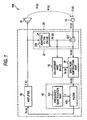
- FIG. 1 is a block diagram of a loudspeaker using a howling suppression apparatus according to a first embodiment of the invention.
- a loudspeaker 100 is an apparatus for adjusting sound volume of ambient acoustics (voice or musical sound) and emitting the acoustics, and comprises a sound collection device 12, a sound emission device 14 and a howling suppression apparatus 20.
- all the signals or acoustics are hereinafter represented as a component (argument z) of a frequency domain conveniently for simplicity of description.
- the sound collection device for example, a microphone
- the howling suppression apparatus 20 generates an acoustic signal Y(z) and outputs the acoustic signal to the sound emission device 14.
- the sound emission device for example, a speaker device
- the sound emission device emits sound waves according to the acoustic signal Y(z).
- the howling suppression apparatus 20 generates the acoustic signal Y (z) by executing processing for suppressing a howling with respect to the acoustic signal X1(z).
- the howling suppression apparatus 20 is a digital signal processor (DSP) comprising an estimation part 22, an adjustment part 32, a spectrum subtraction part 34, a filter part 42 and an amplifier 50.
- DSP digital signal processor
- the howling suppression apparatus 20 is implemented by a central processing unit (CPU) which functions as each element of Fig. 1 by executing a program stored in a computer readable recording medium.
- CPU central processing unit
- the acoustic signal X1(z) generated by the sound collection device 12 is supplied to the estimation part 22.
- an output signal from the sound collection device 12 is actually converted into the digital acoustic signal X1(z) through an A/D converter, but illustration of the A/D converter is omitted for convenience.
- the estimation part 22 generates an estimated signal RE(z) in which the feedback sound signal R(z) is simulated by estimating the feedback sound (R(z)) reaching the sound collection device 12 from the sound emission device 14.
- the estimation part 22 of the embodiment is constructed of a calculation part 221 and an adaptive filter 223.
- the calculation part 221 generates an acoustic signal X2(z) by subtracting the estimated signal RE(z) from the acoustic signal X1(z).
- the acoustic signal X2(z) outputted by the calculation part 221 and the acoustic signal Y(z) (or a signal in which the acoustic signal Y(z) is delayed) supplied to the sound emission device 14 are supplied to the adaptive filter 223.
- the acoustic signal X2(z) is generated by subtracting the estimated signal RE(z) from the acoustic signal X1(z) as shown in the formula (2), and a component of the feedback sound signal R(z) may remain in the acoustic signal X2(z).
- subtraction by the calculation part 221 is actually executed in a time domain, so that even when the estimated signal RE(z) sufficiently approximates to the feedback sound signal R(z), the component of the feedback sound signal R(z) remains in the acoustic signal X2(z) when a phase between the acoustic signal X1(z) and the estimated signal RE (z) differs.
- the component of the feedback sound signal R(z) remaining in the acoustic signal X2 (z) circulates through an acoustic system constructed of the sound emission device 14 and the sound collection device 12, the component increases cumulatively and a howling is caused.
- the adjustment part 32 and the spectrum subtraction part 34 of Fig. 1 are means for suppressing the feedback sound signal R(z) remaining in the acoustic signal X2(z).
- the adjustment part 32 generates an estimated signal SS(z) corresponding to the estimated signal RE (z) by adjusting the estimated signal RE(z) generated by the adaptive filter 223.
- the estimated signal SS(z) is expressed by the following formula (3) including a transfer function HA(z) of the adjustment part 32.
- SS z HA z • RE z
- the spectrum subtraction part 34 generates an acoustic signal X3(z) by subtracting the estimated signal SS(z) according to the estimated signal RE(z) from the acoustic signal X2(z) in a frequency domain (spectrum subtraction). More specifically, the spectrum subtraction part 34 generates the acoustic signal X3(z) by setting a frequency spectrum generated by subtracting a frequency spectrum (an amplitude spectrum or a power spectrum) of the estimated signal SS(z) from a frequency spectrum (an amplitude spectrum or a power spectrum) of the acoustic signal X2 (z) as an amplitude spectrum of the acoustic signal X2(z) as shown in the following formula (4).
- the acoustic signal X2 (z) is a signal in which the estimated signal RE(z) is subtracted from the acoustic signal X1 (z) (formula (1))
- suppression of the estimated signal RE (z) (feedback sound signal R(z)) in the acoustic signal X2(z) becomes excess when the spectrum subtraction part 34 subtracts a frequency spectrum of the estimated signal RE(z) from a frequency spectrum of the acoustic signal X2(z).
- the adjustment part 32 generates the estimated signal SS(z) by decreasing intensity of the estimated signal RE(z).
- a multiplier in which the estimated signal RE (z) is multiplied by a predetermined positive number (for example, less than 1) is suitably adopted as the adjustment part 32.
- a predetermined positive number for example, less than 1
- the adjustment part 32 may execute processing for delaying the estimated signal RE (z) in addition to adjustment of the intensity of the estimated signal RE(z).
- the filter part 42 of Fig. 1 is means for suppressing a component by which the howling is actually caused among the acoustic signal X3(z).
- the filter part 42 comprises a frequency identification part 421 and a filter 423.
- the frequency identification part 421 identifies a frequency (hereinafter called a "howling frequency") F at which a howling is caused.
- a publicly known technique is arbitrarily adopted in identification of the howling frequency F.
- means for identifying the howling frequency F by detecting the peak of a frequency spectrum of the acoustic signal X2(z) or means for identifying the howling frequency F from intensity of each component in which the acoustic signal X2(z) is separated into plural frequency bands is suitable as the frequency identification part 421.
- the filter 423 generates an acoustic signal X4(z) by suppressing a component of a frequency band including the howling frequency F identified by the frequency identification part 421 among the acoustic signal X3(z) after processing by the spectrum subtraction part 34.
- a notch filter for variably controlling frequency characteristics so as to attenuate a narrowband component centering on the howling frequency F among the acoustic signal X3(z) is suitable as the filter 423.
- the howling frequency F is not identified in a situation in which a howling is not caused, so that the filter 423 passes all the components of the acoustic signal X3(z) as the acoustic signal X4(z).
- the amplifier 50 generates an acoustic signal Y(z) by amplifying the acoustic signal X4(z) generated by the filter part 42.
- a gain of the amplifier 50 is variably controlled according to instructions from, for example, a user.
- the acoustic signal Y(z) outputted by the amplifier 50 is supplied to the sound emission device 14 and is emitted as sound waves and also is supplied to the estimation part 22 (adaptive filter 223) and is used in generation of the estimated signal RE(z).
- the acoustic signal Y(z) outputted by the amplifier 50 is actually supplied to the sound emission device 14 after the acoustic signal Y(z) is converted into an analog signal through a D/A converter, but illustration of the D/A converter is omitted for convenience.
- the estimated signal SS(z) is subtracted from the acoustic signal X2(z) in a frequency domain, so that even when a phase between the acoustic signal X2(z) and the estimated signal RE(z) (the estimated signal SS(z)) differs, the feedback sound signal R(z) of the inside of the acoustic signal X2 (z) is suppressed sufficiently. Therefore, a howling can be suppressed effectively as compared with the case of suppressing the howling by only a configuration of subtracting the estimated signal RE(z) from the acoustic signal X1(z) in a time domain.
- a method for suppressing noise by subtracting a frequency spectrum of noise from a frequency spectrum of an acoustic signal has been proposed conventionally. Since the frequency spectrum of noise is estimated using, for example, a silent interval (an interval at which a target sound is not present) among the acoustic signal, the frequency spectrum of noise subtracted from the acoustic signal does not completely match with the frequency spectrum of noise at an interval at which the target sound is present among the acoustic signal. Therefore, there is a problem that a component of noise remaining after subtraction of the frequency spectrum is perceived as harsh musical noise by an audience.
- a feedback sound (feedback sound signal R(z)) is estimated with high accuracy by using the adaptive filter 223, so that musical noise which becomes a problem in the case of subtracting a frequency spectrum of noise from a silent interval of an acoustic signal is resistant to occurrence.
- the feedback sound signal R(z) approximates to a signal S(z) of an amplified sound, so that there is an advantage that noise such as the musical noise is hardly recognized by an audience even when a component of the feedback sound signal R(z) remains in the acoustic signal X4(z).
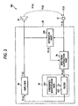
- Fig. 2 is a block diagram of a loudspeaker 100 using a howling suppression apparatus 20 according to a second embodiment of the invention.
- each detailed description is properly omitted by assigning the same numerals as those described above to elements whose actions or functions are equal to those of the first embodiment in each of the following embodiments.
- an acoustic signal X1(z) generated by a sound collection device 12 is supplied to an estimation part 22 (calculation part 221) and a spectrum subtraction part 34.
- An acoustic signal X2(z) generated by the calculation part 221 is not supplied to the spectrum subtraction part 34. That is, the acoustic signal X2(z) is used in only generation (estimation of a feedback sound) of an estimated signal RE(z) by an adaptive filter 223 and is not used in suppression of a feedback sound signal R(z) by the spectrum subtraction part 34.
- the spectrum subtraction part 34 generates an acoustic signal X3(z) using a result of subtracting a frequency spectrum of the estimated signal RE (z) generated by the adaptive filter 223 from a frequency spectrum of the acoustic signal X1(z).
- the estimated signal RE(z) is a signal in which the feedback sound signal R(z) is estimated
- the feedback sound signal R(z) can be suppressed by subtracting the frequency spectrum of the estimated signal RE(z) from the frequency spectrum of the acoustic signal X1(z) by the spectrum subtraction part 34 in a manner similar to the first embodiment. Therefore, an effect similar to that of the first embodiment is achieved also in the present embodiment.
- a configuration in which an adjustment part 32 for generating an estimated signal SS(z) by adjusting the estimated signal RE (z) is arranged between the spectrum subtraction part 34 and the adaptive filter 223 of Fig. 2 and the spectrum subtraction part 34 subtracts the estimated signal SS (z) from the acoustic signal X1(z) is also adopted.
- Fig. 3 is a block diagram of a loudspeaker 100 using a howling suppression apparatus 20 according to a third embodiment of the invention.
- the howling suppression apparatus 20 of Fig. 3 comprises an estimation part 225 instead of the estimation part 22 of Fig. 2 .
- the estimation part 225 generates an estimated signal RE (z) based on an acoustic signal X1(z) generated by a sound collection device 12 and an acoustic signal Y(z) outputted by an amplifier 50 in a manner similar to the estimation part 22.
- the feedback sound signal R(z) is a signal generated from the acoustic signal X1(z), so that an addition of the acoustic signals X1(z) over a sufficiently long time length approximates to a product (or average) of the feedback sound signals R(z) over a sufficiently long time length. Therefore, a transfer function H(z) of the formula (5) is approximately estimated as a transfer function HE(z) of the following formula (6) by using the known acoustic signal X1(z) instead of the unknown feedback sound signal R(z) .
- a symbol " ⁇ " in the formula (6) means an addition (or average) over a time of the extent to which an addition of the feedback sound signals R(z) sufficiently approximates to an addition of the acoustic signals X1(z).
- HE z ⁇ Y * z • X ⁇ 1 z / ⁇ Y * z • Y z
- the estimated signal RE(z) corresponds to a signal in which the feedback sound signal R(z) is estimated.
- a spectrum subtraction part 34 generates an acoustic signal X3(z) by subtracting a frequency spectrum of the estimated signal RE(z) from a frequency spectrum of the acoustic signal X1(z). Therefore, an effect similar to that of the first embodiment is achieved.
- the adaptive filter 223 is not indispensable for estimation of the estimated signal RE(z).
- a configuration in which an adjustment part 32 for adjusting the estimated signal RE (z) to an estimated signal SS (z) is arranged between the spectrum subtraction part 34 and the estimation part 225 of Fig. 3 and the spectrum subtraction part 34 subtracts a frequency spectrum of the estimated signal SS(z) from a frequency spectrum of the acoustic signal X1(z) is also adopted.
- a position (point in time) in which each signal (an acoustic signal or an estimated signal) used in a howling suppression apparatus 20 is converted from one of a time domain and a frequency domain to the other is arbitrary.
- an acoustic signal X2 (z) is converted from the time domain to the frequency domain (for example, a Fourier transform or a wavelet transform) and an estimated signal SS(z) or an estimated signal RE(z) is converted from the time domain to the frequency domain.
- an acoustic signal X1 (z) is converted from the time domain to the frequency domain.
- an acoustic signal X3(z) or an acoustic signal X4(z) is converted from the frequency domain to the time domain (for example, an inverse Fourier transform or an inverse wavelet transform).
- the time domain for example, an inverse Fourier transform or an inverse wavelet transform.
- a method for generating an estimated signal RE(z) (a method for estimating a feedback sound) is not limited to the illustrations described above.
- the estimated signal RE (z) is generated by multiplying an acoustic signal Y(z) outputted by an amplifier 50 by the transfer function H(z).
- the filter part 42 in each of the embodiments described above is omitted.
- an acoustic signal X3(z) is supplied from a spectrum subtraction part 34 to an amplifier 50 as shown in Fig. 4 .
- a position of the filter part 42 in each of the embodiments described above is changed properly.
- the filter part 42 may be arranged between a sound collection device 12 and an estimation part 22 (or an estimation part 225).
- a method for identifying a howling frequency F in the filter part 42 is arbitrary.
- the howling frequency F is identified based on the acoustic signal X2(z), but the howling frequency F can also be identified using acoustic signals (X1(z), X3(z), X4(z), Y(z)) at any stage.
- a configuration of identifying the howling frequency F based on plural filter factors (or a transfer function HE(z) or an estimated signal RE(z) or an estimated signal SS(z)) set by an adaptive filter 223 is adopted.
- a configuration of distributing a howling suppression apparatus 20 into plural apparatuses is also adopted.
- an amplifier 50 is formed in an apparatus different from other elements.
- a part of the howling suppression apparatus 20 may be implemented by a dedicated electronic circuit (DSP) and also the other part may be implemented by cooperation of a central processing unit and a program.
- DSP dedicated electronic circuit
Landscapes
- Health & Medical Sciences (AREA)
- General Health & Medical Sciences (AREA)
- Otolaryngology (AREA)
- Physics & Mathematics (AREA)
- Engineering & Computer Science (AREA)
- Acoustics & Sound (AREA)
- Signal Processing (AREA)
- Circuit For Audible Band Transducer (AREA)
Applications Claiming Priority (1)
| Application Number | Priority Date | Filing Date | Title |
|---|---|---|---|
| JP2008020276A JP5239359B2 (ja) | 2008-01-31 | 2008-01-31 | ハウリング抑制装置 |
Publications (3)
| Publication Number | Publication Date |
|---|---|
| EP2086249A2 EP2086249A2 (en) | 2009-08-05 |
| EP2086249A3 EP2086249A3 (en) | 2009-09-09 |
| EP2086249B1 true EP2086249B1 (en) | 2010-12-29 |
Family
ID=40550192
Family Applications (1)
| Application Number | Title | Priority Date | Filing Date |
|---|---|---|---|
| EP09150514A Not-in-force EP2086249B1 (en) | 2008-01-31 | 2009-01-14 | Howling suppression apparatus and computer readable recording medium |
Country Status (4)
| Country | Link |
|---|---|
| US (1) | US8311237B2 (enExample) |
| EP (1) | EP2086249B1 (enExample) |
| JP (1) | JP5239359B2 (enExample) |
| DE (1) | DE602009000471D1 (enExample) |
Families Citing this family (6)
| Publication number | Priority date | Publication date | Assignee | Title |
|---|---|---|---|---|
| WO2011090386A1 (en) * | 2010-01-19 | 2011-07-28 | Squarehead Technology As | Location dependent feedback cancellation |
| US8891786B1 (en) | 2010-05-17 | 2014-11-18 | Marvell International Ltd. | Selective notch filtering for howling suppression |
| CN102740214B (zh) * | 2011-04-01 | 2014-09-10 | 中国科学院声学研究所 | 一种基于反馈信号频谱估计的啸叫抑制方法 |
| CN106454642B (zh) * | 2016-09-23 | 2019-01-08 | 佛山科学技术学院 | 自适应子带音频反馈抑制方法 |
| CN117561725A (zh) * | 2021-06-30 | 2024-02-13 | 松下电器(美国)知识产权公司 | 啸叫抑制装置、啸叫抑制方法以及啸叫抑制程序 |
| CN114245264A (zh) * | 2021-11-26 | 2022-03-25 | 深圳Tcl新技术有限公司 | 啸叫抑制方法、啸叫抑制装置、电子设备及存储介质 |
Family Cites Families (11)
| Publication number | Priority date | Publication date | Assignee | Title |
|---|---|---|---|---|
| US5442715A (en) | 1992-04-06 | 1995-08-15 | Eastman Kodak Company | Method and apparatus for cursive script recognition |
| US5442712A (en) * | 1992-11-25 | 1995-08-15 | Matsushita Electric Industrial Co., Ltd. | Sound amplifying apparatus with automatic howl-suppressing function |
| US5937060A (en) * | 1996-02-09 | 1999-08-10 | Texas Instruments Incorporated | Residual echo suppression |
| US7054451B2 (en) | 2001-07-20 | 2006-05-30 | Koninklijke Philips Electronics N.V. | Sound reinforcement system having an echo suppressor and loudspeaker beamformer |
| JP4161628B2 (ja) | 2002-07-19 | 2008-10-08 | 日本電気株式会社 | エコー抑圧方法及び装置 |
| JP2004165888A (ja) * | 2002-11-12 | 2004-06-10 | Oki Electric Ind Co Ltd | ハウリング処理装置 |
| JP2005109533A (ja) * | 2003-09-26 | 2005-04-21 | Yamaha Corp | ハウリング抑制装置 |
| CN1736039A (zh) * | 2003-11-11 | 2006-02-15 | 三菱电机株式会社 | 回波抑制装置 |
| WO2005125272A1 (ja) | 2004-06-16 | 2005-12-29 | Matsushita Electric Industrial Co., Ltd. | ハウリング抑圧装置、プログラム、集積回路、およびハウリング抑圧方法 |
| JP4186932B2 (ja) * | 2005-02-07 | 2008-11-26 | ヤマハ株式会社 | ハウリング抑制装置および拡声装置 |
| US8107616B2 (en) * | 2005-10-21 | 2012-01-31 | Koninklijke Philips Electronics N.V. | Acoustic echo canceller |
-
2008
- 2008-01-31 JP JP2008020276A patent/JP5239359B2/ja not_active Expired - Fee Related
-
2009
- 2009-01-14 EP EP09150514A patent/EP2086249B1/en not_active Not-in-force
- 2009-01-14 DE DE602009000471T patent/DE602009000471D1/de active Active
- 2009-01-28 US US12/360,974 patent/US8311237B2/en not_active Expired - Fee Related
Also Published As
| Publication number | Publication date |
|---|---|
| JP5239359B2 (ja) | 2013-07-17 |
| DE602009000471D1 (de) | 2011-02-10 |
| US20090196433A1 (en) | 2009-08-06 |
| EP2086249A3 (en) | 2009-09-09 |
| US8311237B2 (en) | 2012-11-13 |
| JP2009182759A (ja) | 2009-08-13 |
| EP2086249A2 (en) | 2009-08-05 |
Similar Documents
| Publication | Publication Date | Title |
|---|---|---|
| JP6243536B2 (ja) | エコー打ち消し | |
| CN1926911B (zh) | 啸叫抑制装置、程序、集成电路及啸叫抑制方法 | |
| US9210504B2 (en) | Processing audio signals | |
| KR101610656B1 (ko) | 널 프로세싱 노이즈 감산을 이용한 노이즈 억제 시스템 및 방법 | |
| US9723152B2 (en) | Nonlinear echo suppression | |
| KR101601197B1 (ko) | 마이크로폰 어레이의 이득 조정 장치 및 방법 | |
| EP2086249B1 (en) | Howling suppression apparatus and computer readable recording medium | |
| JP4978352B2 (ja) | エコーキャンセラ | |
| KR20060050991A (ko) | 잡음 억제 및 에코 보상을 조합한 음성 신호 처리 | |
| US10978087B2 (en) | Signal processing device, teleconferencing device, and signal processing method | |
| JP4897921B2 (ja) | マルチチャネル音声通信システムにおいて音響エコーを低減するための方法およびシステム | |
| CN109326297B (zh) | 自适应后滤波 | |
| EP2663979B1 (en) | Processing audio signals | |
| JP2010220087A (ja) | 音響処理装置およびプログラム | |
| CN114175606A (zh) | 模块化回波消除单元 | |
| WO2012125231A1 (en) | Apparatus and method for echo suppression | |
| JP2005514668A (ja) | スペクトル出力比依存のプロセッサを有する音声向上システム | |
| CN101765982A (zh) | 回声消除器 | |
| US20240147169A1 (en) | A hearing aid system and a method of operating a hearing aid system | |
| CN117561725A (zh) | 啸叫抑制装置、啸叫抑制方法以及啸叫抑制程序 | |
| US9578426B2 (en) | Method for feedback cancelling in hearing devices and hearing device with a feedback canceller | |
| US20250294298A1 (en) | Hearing aid system and a method of operating a hearing aid system | |
| CN120693788A (zh) | 自动增益控制装置、回波去除装置、自动增益控制方法以及自动增益控制程序 | |
| JP5606731B2 (ja) | 適応型帰還利得補正 | |
| JP5606731B6 (ja) | 適応型帰還利得補正 |
Legal Events
| Date | Code | Title | Description |
|---|---|---|---|
| PUAI | Public reference made under article 153(3) epc to a published international application that has entered the european phase |
Free format text: ORIGINAL CODE: 0009012 |
|
| AK | Designated contracting states |
Kind code of ref document: A2 Designated state(s): AT BE BG CH CY CZ DE DK EE ES FI FR GB GR HR HU IE IS IT LI LT LU LV MC MK MT NL NO PL PT RO SE SI SK TR |
|
| AX | Request for extension of the european patent |
Extension state: AL BA RS |
|
| PUAL | Search report despatched |
Free format text: ORIGINAL CODE: 0009013 |
|
| AK | Designated contracting states |
Kind code of ref document: A3 Designated state(s): AT BE BG CH CY CZ DE DK EE ES FI FR GB GR HR HU IE IS IT LI LT LU LV MC MK MT NL NO PL PT RO SE SI SK TR |
|
| AX | Request for extension of the european patent |
Extension state: AL BA RS |
|
| 17P | Request for examination filed |
Effective date: 20100304 |
|
| AKX | Designation fees paid |
Designated state(s): DE FR GB |
|
| GRAP | Despatch of communication of intention to grant a patent |
Free format text: ORIGINAL CODE: EPIDOSNIGR1 |
|
| GRAS | Grant fee paid |
Free format text: ORIGINAL CODE: EPIDOSNIGR3 |
|
| GRAA | (expected) grant |
Free format text: ORIGINAL CODE: 0009210 |
|
| AK | Designated contracting states |
Kind code of ref document: B1 Designated state(s): DE FR GB |
|
| REG | Reference to a national code |
Ref country code: GB Ref legal event code: FG4D |
|
| REF | Corresponds to: |
Ref document number: 602009000471 Country of ref document: DE Date of ref document: 20110210 Kind code of ref document: P |
|
| REG | Reference to a national code |
Ref country code: DE Ref legal event code: R096 Ref document number: 602009000471 Country of ref document: DE Effective date: 20110210 |
|
| PLBE | No opposition filed within time limit |
Free format text: ORIGINAL CODE: 0009261 |
|
| STAA | Information on the status of an ep patent application or granted ep patent |
Free format text: STATUS: NO OPPOSITION FILED WITHIN TIME LIMIT |
|
| 26N | No opposition filed |
Effective date: 20110930 |
|
| REG | Reference to a national code |
Ref country code: FR Ref legal event code: ST Effective date: 20111125 |
|
| REG | Reference to a national code |
Ref country code: DE Ref legal event code: R097 Ref document number: 602009000471 Country of ref document: DE Effective date: 20110930 |
|
| PG25 | Lapsed in a contracting state [announced via postgrant information from national office to epo] |
Ref country code: FR Free format text: LAPSE BECAUSE OF NON-PAYMENT OF DUE FEES Effective date: 20110228 |
|
| PGFP | Annual fee paid to national office [announced via postgrant information from national office to epo] |
Ref country code: DE Payment date: 20160105 Year of fee payment: 8 |
|
| PGFP | Annual fee paid to national office [announced via postgrant information from national office to epo] |
Ref country code: GB Payment date: 20160113 Year of fee payment: 8 |
|
| REG | Reference to a national code |
Ref country code: DE Ref legal event code: R119 Ref document number: 602009000471 Country of ref document: DE |
|
| GBPC | Gb: european patent ceased through non-payment of renewal fee |
Effective date: 20170114 |
|
| PG25 | Lapsed in a contracting state [announced via postgrant information from national office to epo] |
Ref country code: GB Free format text: LAPSE BECAUSE OF NON-PAYMENT OF DUE FEES Effective date: 20170114 Ref country code: DE Free format text: LAPSE BECAUSE OF NON-PAYMENT OF DUE FEES Effective date: 20170801 |