EP2085555A2 - Verfahren zum Einkuppeln und Auskuppeln eines Öffnungs- und Schließmechanismus für Fahrzeugtüren von einem entsprechenden Antriebsmotor aus - Google Patents
Verfahren zum Einkuppeln und Auskuppeln eines Öffnungs- und Schließmechanismus für Fahrzeugtüren von einem entsprechenden Antriebsmotor aus Download PDFInfo
- Publication number
- EP2085555A2 EP2085555A2 EP09380004A EP09380004A EP2085555A2 EP 2085555 A2 EP2085555 A2 EP 2085555A2 EP 09380004 A EP09380004 A EP 09380004A EP 09380004 A EP09380004 A EP 09380004A EP 2085555 A2 EP2085555 A2 EP 2085555A2
- Authority
- EP
- European Patent Office
- Prior art keywords
- support plate
- drive motor
- angular lever
- motor
- shaft
- Prior art date
- Legal status (The legal status is an assumption and is not a legal conclusion. Google has not performed a legal analysis and makes no representation as to the accuracy of the status listed.)
- Granted
Links
Images

Classifications
-
- E—FIXED CONSTRUCTIONS
- E05—LOCKS; KEYS; WINDOW OR DOOR FITTINGS; SAFES
- E05F—DEVICES FOR MOVING WINGS INTO OPEN OR CLOSED POSITION; CHECKS FOR WINGS; WING FITTINGS NOT OTHERWISE PROVIDED FOR, CONCERNED WITH THE FUNCTIONING OF THE WING
- E05F15/00—Power-operated mechanisms for wings
- E05F15/60—Power-operated mechanisms for wings using electrical actuators
- E05F15/603—Power-operated mechanisms for wings using electrical actuators using rotary electromotors
- E05F15/611—Power-operated mechanisms for wings using electrical actuators using rotary electromotors for swinging wings
- E05F15/63—Power-operated mechanisms for wings using electrical actuators using rotary electromotors for swinging wings operated by swinging arms
-
- E—FIXED CONSTRUCTIONS
- E05—LOCKS; KEYS; WINDOW OR DOOR FITTINGS; SAFES
- E05F—DEVICES FOR MOVING WINGS INTO OPEN OR CLOSED POSITION; CHECKS FOR WINGS; WING FITTINGS NOT OTHERWISE PROVIDED FOR, CONCERNED WITH THE FUNCTIONING OF THE WING
- E05F15/00—Power-operated mechanisms for wings
- E05F15/60—Power-operated mechanisms for wings using electrical actuators
- E05F15/603—Power-operated mechanisms for wings using electrical actuators using rotary electromotors
- E05F15/632—Power-operated mechanisms for wings using electrical actuators using rotary electromotors for horizontally-sliding wings
-
- E—FIXED CONSTRUCTIONS
- E05—LOCKS; KEYS; WINDOW OR DOOR FITTINGS; SAFES
- E05F—DEVICES FOR MOVING WINGS INTO OPEN OR CLOSED POSITION; CHECKS FOR WINGS; WING FITTINGS NOT OTHERWISE PROVIDED FOR, CONCERNED WITH THE FUNCTIONING OF THE WING
- E05F15/00—Power-operated mechanisms for wings
- E05F15/60—Power-operated mechanisms for wings using electrical actuators
- E05F15/603—Power-operated mechanisms for wings using electrical actuators using rotary electromotors
-
- E—FIXED CONSTRUCTIONS
- E05—LOCKS; KEYS; WINDOW OR DOOR FITTINGS; SAFES
- E05F—DEVICES FOR MOVING WINGS INTO OPEN OR CLOSED POSITION; CHECKS FOR WINGS; WING FITTINGS NOT OTHERWISE PROVIDED FOR, CONCERNED WITH THE FUNCTIONING OF THE WING
- E05F15/00—Power-operated mechanisms for wings
- E05F15/60—Power-operated mechanisms for wings using electrical actuators
- E05F15/603—Power-operated mechanisms for wings using electrical actuators using rotary electromotors
- E05F15/632—Power-operated mechanisms for wings using electrical actuators using rotary electromotors for horizontally-sliding wings
- E05F15/643—Power-operated mechanisms for wings using electrical actuators using rotary electromotors for horizontally-sliding wings operated by flexible elongated pulling elements, e.g. belts, chains or cables
- E05F15/646—Power-operated mechanisms for wings using electrical actuators using rotary electromotors for horizontally-sliding wings operated by flexible elongated pulling elements, e.g. belts, chains or cables allowing or involving a secondary movement of the wing, e.g. rotational or transversal
-
- E—FIXED CONSTRUCTIONS
- E05—LOCKS; KEYS; WINDOW OR DOOR FITTINGS; SAFES
- E05F—DEVICES FOR MOVING WINGS INTO OPEN OR CLOSED POSITION; CHECKS FOR WINGS; WING FITTINGS NOT OTHERWISE PROVIDED FOR, CONCERNED WITH THE FUNCTIONING OF THE WING
- E05F15/00—Power-operated mechanisms for wings
- E05F15/60—Power-operated mechanisms for wings using electrical actuators
- E05F15/603—Power-operated mechanisms for wings using electrical actuators using rotary electromotors
- E05F15/632—Power-operated mechanisms for wings using electrical actuators using rotary electromotors for horizontally-sliding wings
- E05F15/649—Power-operated mechanisms for wings using electrical actuators using rotary electromotors for horizontally-sliding wings operated by swinging arms
-
- E—FIXED CONSTRUCTIONS
- E05—LOCKS; KEYS; WINDOW OR DOOR FITTINGS; SAFES
- E05Y—INDEXING SCHEME ASSOCIATED WITH SUBCLASSES E05D AND E05F, RELATING TO CONSTRUCTION ELEMENTS, ELECTRIC CONTROL, POWER SUPPLY, POWER SIGNAL OR TRANSMISSION, USER INTERFACES, MOUNTING OR COUPLING, DETAILS, ACCESSORIES, AUXILIARY OPERATIONS NOT OTHERWISE PROVIDED FOR, APPLICATION THEREOF
- E05Y2900/00—Application of doors, windows, wings or fittings thereof
- E05Y2900/50—Application of doors, windows, wings or fittings thereof for vehicles
- E05Y2900/51—Application of doors, windows, wings or fittings thereof for vehicles for railway cars or mass transit vehicles
Definitions
- the invention relates to a device for coupling/engaging and uncoupling/disengaging an opening and closing mechanism for vehicle doors, such as a public transport vehicle, from a corresponding drive motor, generally an electric motor.
- an emergency mechanism for passenger vehicle doors is known, which is applicable to mechanisms comprising an electric motor, a speed reducer and a gearbox the output pinion of which is coupled to a gear wheel integral with a vertical bar on which the door is supported.
- the mechanism comprises a mobile plate on which the electric motor and the speed reducer are fixed, the mobile plate being superimposed onto the gearbox and being able to rotate in both directions about a shaft by the action of actuating means, said rotation causing the radial movement of the output pinion of the speed reducer between two positions, a gearing position and an ungearing position in relation to the gearbox.
- the actuating means comprise a first class lever in which the power arm is subjected to the action of a spring working permanently under traction, the fulcrum is arranged in the gearbox and the resistance arm is articulately coupled at its outer end to an end of a thrust arm the other end of which is articulately coupled to the mobile plate.
- the traction element of the lever is coupled at the same end of the resistance arm for its actuation.
- the latter which is larger in size, is arranged between the lever and the output pinion of the reducer unit.
- a main objective of the present invention is to disclose an alternative solution to the variant described above, and specifically to disclose a variant which is more compact and in which the coupling between the traction element of the lever and the mentioned lever is more easily accessible.
- the device according to the invention is of those comprising a speed reducer unit, suitable for being fixed to the chassis of the vehicle and provided with a driven gear wheel which in normal operating conditions is gear coupled with the shaft of the drive motor, the device comprising a support plate for supporting the drive motor, which can rotate in both directions about a shaft integral with the speed reducer unit, and movement means for moving the support plate of the motor.
- the device is essentially characterised in that said movement means for moving the support plate of the motor comprise a first class angular lever, actuatable from outside the device, the fulcrum of which is a rotation point fixed to the speed reducer unit and the resistance arm of which comprises a first end portion, provided with a bar articulated thereto and to a point of the support plate, and a side appendage defining a second end portion, and in that the mentioned second end portion is subjected to the action of elastic means tending to move the lever towards a stable position of coupling between the gear wheel and the shaft of the motor when it is actuated such that it causes the rotation of the support plate and consequently a side movement of the shaft of the motor, the latter being uncoupled from the gear wheel and therefore from the opening and closing mechanism.
- said movement means for moving the support plate of the motor comprise a first class angular lever, actuatable from outside the device, the fulcrum of which is a rotation point fixed to the speed reducer unit and the resistance arm of which comprises
- the lever is not straight but rather it is angular, it is bent, which allows an optimal location of its ends and of the corresponding components linked to the mentioned ends. Furthermore, the portion on which the elastic means and the articulated bar for the connection with the support plate act is located on the resistance arm of the angular lever, i.e., on one and the same side of the fulcrum of the angular lever.
- connection line between the fulcrum of the angular lever and the articulated connection thereof with the bar and the connection line between the two articulated connections of said bar with the angular lever and with the support plate, respectively form an angle ⁇ greater than 180°, seen from the position of the drive motor.
- the elastic means are made up of a traction spring, connected at one of its ends to the second end portion of the resistance arm of the angular lever and at its other end to a fixed point of the speed reducer unit.
- the device comprises actuation means for actuating the angular lever and such means comprise a traction element connected to the power arm of the lever.
- the angular lever is bent at an angle, the fulcrum of the angular lever being arranged at the vertex of the mentioned angle, and the drive motor is fixed to the support plate such that its rotation shaft is arranged closer to the fulcrum of the angular lever than the rotation shaft about which the gear wheel rotates.
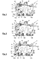
- a device 1 for coupling and uncoupling an opening and closing mechanism for vehicle doors from a corresponding drive motor, not shown, has been depicted in Figures 1 to 3 .
- the device 1 comprises a support plate 5 for supporting the drive motor, superimposed onto the reducer unit and which can rotate in both directions about a shaft 6 integral with the mentioned speed reducer unit.
- the device 1 further comprises movement means 7 for moving the support plate 5 of the motor, made up of a first class angular lever 8, actuatable from outside the device, the fulcrum 9 of which is a rotation point fixed to the speed reducer unit and the resistance arm 10 of which comprises a first end portion 11, provided with a bar 12 articulated thereto and to a point 12b of the support plate, and a side appendage defining a second end portion 14.
- the device 1 also comprises actuation means 15 for actuating the angular lever 8 comprising a traction element 17 connected to the power arm 16 of the lever, i.e., to the other side of the fulcrum in which there are located the first end portion 11 and the second end portion 14 of the angular lever connecting it with the support plate 5 and with the elastic means 13, respectively.
- This relative position between the articulated parts of the angular lever 8 ensures that the drive motor 2 and the gear wheel 4 remain coupled during the operation of the motor due to the interlocking effect caused by the fixed points corresponding to the fulcrum 9 of the angular lever 8 and the end of the runners 21 and 22, made in the support plate 5, when it abuts against corresponding pins integral with the reducer unit.
Landscapes
- Power-Operated Mechanisms For Wings (AREA)
- Connection Of Motors, Electrical Generators, Mechanical Devices, And The Like (AREA)
Applications Claiming Priority (1)
| Application Number | Priority Date | Filing Date | Title |
|---|---|---|---|
| ES200800250A ES2332760B1 (es) | 2008-01-31 | 2008-01-31 | Dispositivo para acoplar y desacoplar un mecanismo de apertura y cierre de puertas de vehiculos de un correspondiente motor de accionamiento. |
Publications (3)
| Publication Number | Publication Date |
|---|---|
| EP2085555A2 true EP2085555A2 (de) | 2009-08-05 |
| EP2085555A3 EP2085555A3 (de) | 2009-11-18 |
| EP2085555B1 EP2085555B1 (de) | 2011-06-29 |
Family
ID=40602240
Family Applications (1)
| Application Number | Title | Priority Date | Filing Date |
|---|---|---|---|
| EP09380004A Active EP2085555B1 (de) | 2008-01-31 | 2009-01-21 | Kupplungseinrichtung eines Öffnungs- und Schließmechanismus für Fahrzeugtüren mit einem Antriebsmotor |
Country Status (2)
| Country | Link |
|---|---|
| EP (1) | EP2085555B1 (de) |
| ES (1) | ES2332760B1 (de) |
Cited By (1)
| Publication number | Priority date | Publication date | Assignee | Title |
|---|---|---|---|---|
| JP2015140519A (ja) * | 2014-01-27 | 2015-08-03 | 株式会社ミツバ | 車両用開閉体の制御装置 |
Citations (1)
| Publication number | Priority date | Publication date | Assignee | Title |
|---|---|---|---|---|
| ES2162758A1 (es) | 2000-02-14 | 2002-01-01 | Masats Sa | Mecanismo de mergencia para puertas de vehiculos de pasajeros. |
Family Cites Families (1)
| Publication number | Priority date | Publication date | Assignee | Title |
|---|---|---|---|---|
| DE19927169A1 (de) * | 1999-06-15 | 2000-12-21 | Bode Gmbh & Co Kg | Elektromechanischer Antrieb für eine Drehsäule zur Bewegung eines Türflügels einer Innenschwenk- oder Außenschwingtür an einem Fahrzeug, insbesondere einem öffentlichen Verkehrsmittel |
-
2008
- 2008-01-31 ES ES200800250A patent/ES2332760B1/es active Active
-
2009
- 2009-01-21 EP EP09380004A patent/EP2085555B1/de active Active
Patent Citations (1)
| Publication number | Priority date | Publication date | Assignee | Title |
|---|---|---|---|---|
| ES2162758A1 (es) | 2000-02-14 | 2002-01-01 | Masats Sa | Mecanismo de mergencia para puertas de vehiculos de pasajeros. |
Cited By (1)
| Publication number | Priority date | Publication date | Assignee | Title |
|---|---|---|---|---|
| JP2015140519A (ja) * | 2014-01-27 | 2015-08-03 | 株式会社ミツバ | 車両用開閉体の制御装置 |
Also Published As
| Publication number | Publication date |
|---|---|
| ES2332760B1 (es) | 2011-01-07 |
| EP2085555B1 (de) | 2011-06-29 |
| EP2085555A3 (de) | 2009-11-18 |
| ES2332760A1 (es) | 2010-02-11 |
Similar Documents
| Publication | Publication Date | Title |
|---|---|---|
| US20120274084A1 (en) | Motor vehicle lock | |
| TWI451021B (zh) | 翻板接頭 | |
| JP6832237B2 (ja) | 自転車の電動ディレイラ | |
| CN1853026B (zh) | 摆动门设备中设置有门关闭器的改进装置 | |
| CN109681072A (zh) | 具有齿杆曲柄机构的动力门 | |
| EP1854953A3 (de) | Automatisches Türsystem | |
| US20070114960A1 (en) | Actuating device for a movable component | |
| EP1710377A2 (de) | Kraftangetriebene Schliessvorrichtung | |
| EP2634048A1 (de) | Scharnier zur Gelenkverbindung einer Motorhaube an das Chassis eines Fahrzeugs | |
| CN101512093A (zh) | 家具铰链 | |
| CN105386674A (zh) | 用于对机动车中的组件进行调节的驱动装置 | |
| AU2005289424B2 (en) | Electrically driven entryway actuation system | |
| US8234745B2 (en) | Motor device and wiper apparatus | |
| EP2085555B1 (de) | Kupplungseinrichtung eines Öffnungs- und Schließmechanismus für Fahrzeugtüren mit einem Antriebsmotor | |
| EP1813465A3 (de) | Sitz mit integriertem Gurt und Heber | |
| US8430446B2 (en) | Spindle drive | |
| CN103161638B (zh) | 用于内燃机的起动机 | |
| US10480224B2 (en) | Power driven vehicle latch with non-uniform gears | |
| AU3820102A (en) | Emergency release mechanism for electrical bus door operator | |
| EP2405091B1 (de) | Antrieb für schwenkbare Türen | |
| EP3577293B1 (de) | Umkehrbare aktivierungseinheit zum alternativen aufprall zweier separater kraftfahrzeugfunktionselemente | |
| CN103003108B (zh) | 雨刷装置 | |
| US7290823B2 (en) | Closing unit | |
| WO2007129296A1 (en) | Actuator for an automobile | |
| JP2010196254A (ja) | 移動体駆動装置 |
Legal Events
| Date | Code | Title | Description |
|---|---|---|---|
| PUAI | Public reference made under article 153(3) epc to a published international application that has entered the european phase |
Free format text: ORIGINAL CODE: 0009012 |
|
| AK | Designated contracting states |
Kind code of ref document: A2 Designated state(s): AT BE BG CH CY CZ DE DK EE ES FI FR GB GR HR HU IE IS IT LI LT LU LV MC MK MT NL NO PL PT RO SE SI SK TR |
|
| AX | Request for extension of the european patent |
Extension state: AL BA RS |
|
| PUAL | Search report despatched |
Free format text: ORIGINAL CODE: 0009013 |
|
| AK | Designated contracting states |
Kind code of ref document: A3 Designated state(s): AT BE BG CH CY CZ DE DK EE ES FI FR GB GR HR HU IE IS IT LI LT LU LV MC MK MT NL NO PL PT RO SE SI SK TR |
|
| AX | Request for extension of the european patent |
Extension state: AL BA RS |
|
| RIC1 | Information provided on ipc code assigned before grant |
Ipc: E05F 15/12 20060101ALI20091012BHEP Ipc: E05F 15/10 20060101ALI20091012BHEP Ipc: E05F 15/14 20060101AFI20090514BHEP |
|
| 17P | Request for examination filed |
Effective date: 20100421 |
|
| AKX | Designation fees paid |
Designated state(s): DE IT NL TR |
|
| GRAP | Despatch of communication of intention to grant a patent |
Free format text: ORIGINAL CODE: EPIDOSNIGR1 |
|
| GRAS | Grant fee paid |
Free format text: ORIGINAL CODE: EPIDOSNIGR3 |
|
| GRAA | (expected) grant |
Free format text: ORIGINAL CODE: 0009210 |
|
| AK | Designated contracting states |
Kind code of ref document: B1 Designated state(s): DE IT NL TR |
|
| REG | Reference to a national code |
Ref country code: NL Ref legal event code: T3 |
|
| REG | Reference to a national code |
Ref country code: DE Ref legal event code: R096 Ref document number: 602009001683 Country of ref document: DE Effective date: 20110908 |
|
| PLBE | No opposition filed within time limit |
Free format text: ORIGINAL CODE: 0009261 |
|
| STAA | Information on the status of an ep patent application or granted ep patent |
Free format text: STATUS: NO OPPOSITION FILED WITHIN TIME LIMIT |
|
| 26N | No opposition filed |
Effective date: 20120330 |
|
| REG | Reference to a national code |
Ref country code: DE Ref legal event code: R097 Ref document number: 602009001683 Country of ref document: DE Effective date: 20120330 |
|
| P01 | Opt-out of the competence of the unified patent court (upc) registered |
Effective date: 20230527 |
|
| PGFP | Annual fee paid to national office [announced via postgrant information from national office to epo] |
Ref country code: NL Payment date: 20260126 Year of fee payment: 18 |
|
| PGFP | Annual fee paid to national office [announced via postgrant information from national office to epo] |
Ref country code: DE Payment date: 20260130 Year of fee payment: 18 |
|
| PGFP | Annual fee paid to national office [announced via postgrant information from national office to epo] |
Ref country code: IT Payment date: 20260127 Year of fee payment: 18 |
|
| PGFP | Annual fee paid to national office [announced via postgrant information from national office to epo] |
Ref country code: TR Payment date: 20260121 Year of fee payment: 18 |