EP2085336A1 - Vorrichtung zum Transport einer Palette - Google Patents
Vorrichtung zum Transport einer Palette Download PDFInfo
- Publication number
- EP2085336A1 EP2085336A1 EP09100061A EP09100061A EP2085336A1 EP 2085336 A1 EP2085336 A1 EP 2085336A1 EP 09100061 A EP09100061 A EP 09100061A EP 09100061 A EP09100061 A EP 09100061A EP 2085336 A1 EP2085336 A1 EP 2085336A1
- Authority
- EP
- European Patent Office
- Prior art keywords
- sheet
- transport rollers
- pallet
- transfer conveyor
- conveyor
- Prior art date
- Legal status (The legal status is an assumption and is not a legal conclusion. Google has not performed a legal analysis and makes no representation as to the accuracy of the status listed.)
- Granted
Links
- 241000252254 Catostomidae Species 0.000 description 1
- 238000007664 blowing Methods 0.000 description 1
- 238000000151 deposition Methods 0.000 description 1
- 238000000926 separation method Methods 0.000 description 1
Images


Classifications
-
- B—PERFORMING OPERATIONS; TRANSPORTING
- B65—CONVEYING; PACKING; STORING; HANDLING THIN OR FILAMENTARY MATERIAL
- B65G—TRANSPORT OR STORAGE DEVICES, e.g. CONVEYORS FOR LOADING OR TIPPING, SHOP CONVEYOR SYSTEMS OR PNEUMATIC TUBE CONVEYORS
- B65G57/00—Stacking of articles
-
- B—PERFORMING OPERATIONS; TRANSPORTING
- B41—PRINTING; LINING MACHINES; TYPEWRITERS; STAMPS
- B41F—PRINTING MACHINES OR PRESSES
- B41F21/00—Devices for conveying sheets through printing apparatus or machines
-
- B—PERFORMING OPERATIONS; TRANSPORTING
- B65—CONVEYING; PACKING; STORING; HANDLING THIN OR FILAMENTARY MATERIAL
- B65G—TRANSPORT OR STORAGE DEVICES, e.g. CONVEYORS FOR LOADING OR TIPPING, SHOP CONVEYOR SYSTEMS OR PNEUMATIC TUBE CONVEYORS
- B65G47/00—Article or material-handling devices associated with conveyors; Methods employing such devices
- B65G47/52—Devices for transferring articles or materials between conveyors i.e. discharging or feeding devices
- B65G47/53—Devices for transferring articles or materials between conveyors i.e. discharging or feeding devices between conveyors which cross one another
- B65G47/54—Devices for transferring articles or materials between conveyors i.e. discharging or feeding devices between conveyors which cross one another at least one of which is a roller-way
Definitions
- the invention relates to a device for transporting a pallet on which a stack of sheets is arranged, which is to be supplied to a sheet-processing machine.
- conveyor systems are provided, the z. B. consist of several juxtaposed roller systems, which together form a roller conveyor.
- An intended for processing sheet stack is placed on a pallet, placed by means of a lift truck on the roller conveyor and then fed to the feeder of a sheet-processing machine.
- Such a conveyor system is z. B. by the DE 101 22 428 A1 known.
- This shows a sheet-processing machine with a sheet feeder and a conveyor line, by means of which the sheet feeder laterally arranged on a pallet stack of sheets can be fed.
- the conveyor line has, in addition to the feeder on a Bogenstapelvorausrichtstation and a transfer conveyor.
- the transfer conveyor has a receptacle for support elements of the lift truck, which is arranged in the transport direction of the pallet.
- the invention has for its object to provide a transfer conveyor, which is querferbar transversely to the pallet transport direction.
- the transfer conveyor a transversely oriented to the direction of the pallet transport path recording for a pallet carrying support elements, for. B. a Hubwagengabel having.
- the sheet processing machine can be advantageously operated with a standard pallet for all sheet formats.
- shortened rollers are arranged in the region of the receptacle.
- the range is well supported even in the field of recording.
- seven of nine support feet of the pallet are constantly supported by the transport rollers of the transfer conveyor. All transport rollers of the transfer conveyor have a preferably common drive.
- a printing press 1 has a feeder 2, at least one printing unit 3 or 4 and a boom 6 on.
- the sheets 7 are removed from a sheet stack 8 and isolated or scaly fed via a feed table 9 the printing units 3 and 4.
- These contain in a known manner in each case a plate cylinder 11, 12 and thus cooperating blanket cylinder 15, 20.
- the plate cylinder 11 and 12 each have a clamping device 13, 14 for attaching flexible printing plates.
- each plate cylinder 11, 12 is associated with a device 16, 17 for the semi-automatic or fully automatic printing plate change.
- the sheet stack 8 rests on a controllably liftable stacking plate.
- the removal of the sheet 7 takes place from the top of the sheet stack 8 by means of a so-called suction head 18, which has, inter alia, a number of lifting and Schleppsaugem 19, 21 for the separation of the sheet 7.
- blowing devices 22 are provided for loosening the upper sheet layers and sensing elements 23 for stack tracking.
- a number of lateral and rear stops 24 are provided for aligning the sheet stack 8, in particular the upper sheet 7 of the sheet pile 8.
- the feeder 2 is associated with a conveyor system 26, which 2 pallets 27 to the stacking plate of the investor and delivers away.
- the conveyor system 26 is transverse to the sheet processing direction (arrow in FIG. 2 ) of the printing machine 1 and consists of a transfer conveyor 28, a Bogenstapelvorausschurgisstation 29 and a discharge element 31 for pallets 27, z. B. empty pallets.
- the transfer conveyor 28 has a number of drivable transport rollers 32 which are arranged side by side and form a transport plane for pallets 27.
- the transport rollers 32 are arranged in their axial alignment parallel to the sheet transport direction of the printing press 1, so that a transport direction for the pallets 27 and arranged on the pallet stack of sheets 8 transversely to the sheet transport direction of Printing press 1 results. By this measure, the sheet stack 8 are fed to the feeder 2 side.
- the transfer conveyor 28 has in a central region a receptacle, preferably two parallel arranged in the axial direction of the rollers 32 shots 33, 34 for support members 36, 37, z. B. a Hubwagengabel a lift truck 38, on. Between the receptacles 33, 34 transport rollers 32 are arranged, which correspond to the side of the receptacles 33, 34 arranged rollers 32. In an extension of the receptacles 33, 34 each shortened transport rollers 39 are arranged.
- the processed pallets 27 preferably have nine support legs 35. These are carried by the transport rollers 32 when depositing the pallet 27 onto the transfer conveyor 28. When transporting the pallet 27 in each case two support legs 35 reach into the region of the receptacles 33, 34 and are not supported there. Due to the arrangement of the shortened transport rollers 39, however, at least seven support legs 35 of the pallet 27 are always supported.
- All transport rollers 32, 39 have a preferably common drive 40.
Landscapes
- Engineering & Computer Science (AREA)
- Mechanical Engineering (AREA)
- Feeding Of Articles By Means Other Than Belts Or Rollers (AREA)
- Sheets, Magazines, And Separation Thereof (AREA)
- Pile Receivers (AREA)
- Delivering By Means Of Belts And Rollers (AREA)
- Feeding Of Workpieces (AREA)
- Pallets (AREA)
- Chain Conveyers (AREA)
- Registering Or Overturning Sheets (AREA)
- Relays Between Conveyors (AREA)
Abstract
Description
- Die Erfindung betrifft eine Vorrichtung zum Transport einer Palette, auf welcher ein Bogenstapel angeordnet ist, der einer Bogen verarbeitenden Maschine zugeführt werden soll.
- Zur Belieferung von Bogen verarbeitenden Maschinen, insbesondere Druckmaschinen, sind Fördersysteme vorgesehen, die z. B. aus mehreren nebeneinander angeordneten Rollensystemen bestehen, die zusammen eine Rollenbahn bilden. Ein zur Verarbeitung vorgesehener Bogenstapel wird auf einer Palette angeordnet, mittels eines Hubwagens auf die Rollenbahn aufgesetzt und daraufhin dem Anleger einer Bogen verarbeitenden Maschine zugeführt.
- Ein derartiges Fördersystem ist z. B. durch die
DE 101 22 428 A1 bekannt. Diese zeigt eine Bogen verarbeitende Maschine mit einem Bogenanleger und einer Förderstrecke, mittels welcher dem Bogenanleger seitlich ein auf einer Palette angeordneter Bogenstapel zuführbar ist. Die Förderstrecke weist neben dem Anleger eine Bogenstapelvorausrichtstation und einen Übergabeförderer auf. Der Übergabeförderer weist eine Aufnahme für Tragelemente des Hubwagens auf, welche in Transportrichtung der Palette angeordnet ist. - Bei der Verarbeitung von Bogenformaten, die kleiner als das Palettenformat sind, müssen diese für eine spätere Ausrichtung des Bogenstapels außerzentrisch auf der Palette angeordnet sein. Diese Maßnahme führt jedoch zu einer ungünstigen Gewichtsverteilung des Stapels auf der Palette und kann im schlimmsten Fall zu einem Kippen des Hubwagens führen.
- Der Erfindung liegt die Aufgabe zugrunde, einen Übergabeförderer zu schaffen, der quer zur Palettentransportrichtung belieferbar ist.
- Die Aufgabe wird erfindungsgemäß durch die Merkmale des Anspruchs 1 gelöst.
- Es ist ein besonderer Vorteil der Erfindung, dass der Übergabeförderer eine quer zur Richtung der Palettentransportstrecke ausgerichtete Aufnahme für eine Palette tragende Tragelemente, z. B. eine Hubwagengabel, aufweist. Durch diese Maßnahme können Bogenstapel sicher aufgenommen werden, die ein kleineres Format aufweisen, als die sie tragende Palette.
- Auf diese Weise kann die Bogen verarbeitende Maschine in vorteilhafter Weise mit einer Standardpalette für alle Bogenformate betrieben werden.
- In vorteilhafter Ausgestaltung sind im Bereich der Aufnahme verkürzte Rollen angeordnet. Durch diese Maßnahme wird die Palette auch im Bereich der Aufnahme gut abgestützt. Vorzugsweise werden ständig sieben von neun Stützfüßen der Palette von den Transportrollen des Übergabeförderers abgestützt. Sämtliche Transportrollen des Übergabeförderers weisen einen vorzugsweise gemeinsamen Antrieb auf.
- Ein Ausführungsbeispiel der Erfindung ist in den Zeichnungen dargestellt und wird im Folgenden beschrieben.
-
- Figur 1
- eine Bogenrotationsdruckmaschine im Schnitt in schematischer Darstellung,
- Figur 2
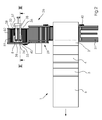
- eine Draufsicht auf die Druckmaschine mit Fördersystem für Bogenstapel,
- Figur 3
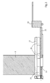
- den Übergabeförderer mit Palette und Bogenstapel im Schnitt in schematischer Darstellung,
- Figur 4
- einen Übergabeförderer in perspektivischer Ansicht von oben und
- Figur 5
- den Übergabeförderer in perspektivischer Ansicht von unten.
- Eine Bogen 7 verarbeitende Maschine, z. B. eine Druckmaschine 1, weist einen Anleger 2, mindestens ein Druckwerk 3 bzw. 4 und einen Ausleger 6 auf. Die Bogen 7 werden von einem Bogenstapel 8 entnommen und vereinzelt oder schuppenförmig über einen Zuführtisch 9 den Druckwerken 3 und 4 zugeführt. Diese enthalten in bekannter Weise jeweils einen Plattenzylinder 11, 12 und damit jeweils zusammenwirkende Gummituchzylinder 15, 20. Die Plattenzylinder 11 und 12 weisen jeweils eine Klemmvorrichtung 13, 14 zum Befestigen flexibler Druckplatten auf. Darüber hinaus ist jedem Plattenzylinder 11, 12 eine Vorrichtung 16, 17 für den halb- oder vollautomatischern Druckplattenwechsel zugeordnet.
- Der Bogenstapel 8 liegt auf einer gesteuert anhebbaren Stapelplatte auf. Die Entnahme der Bogen 7 erfolgt von der Oberseite des Bogenstapels 8 mittels eines so genannten Saugkopfes 18, der unter anderem eine Anzahl von Hub- und Schleppsaugem 19, 21 für die Vereinzelung der Bogen 7 aufweist. Darüber hinaus sind Blaseinrichtungen 22 zur Auflockerung der oberen Bogenlagen und Tastelemente 23 zur Stapelnachführung vorgesehen. Zur Ausrichtung des Bogenstapels 8, insbesondere der oberen Bogen 7 des Bogenstapels 8 sind eine Anzahl von seitlichen und hinteren Anschlägen 24 vorgesehen.
- Dem Anleger 2 ist ein Fördersystem 26 zugeordnet, welches der Stapelplatte des Anlegers 2 Paletten 27 zu- und abfördert. Das Fördersystem 26 ist quer zur Bogenverarbeitungsrichtung (Pfeil in
Figur 2 ) der Druckmaschine 1 angeordnet und besteht aus einem Übergabeförderer 28, einer Bogenstapelvorausrichtungsstation 29 und einem Ausschleuselement 31 für Paletten 27, z. B. Leerpaletten. - Der Übergabeförderer 28 weist eine Anzahl von antreibbaren Transportrollen 32 auf, die nebeneinander angeordnet sind und eine Transportebene für Paletten 27 bilden. Die Transportrollen 32 sind in ihrer axialen Ausrichtung parallel zur Bogentransportrichtung der Druckmaschine 1 angeordnet, so dass sich eine Transportrichtung für die Paletten 27 und dem auf der Palette angeordneten Bogenstapel 8 quer zur Bogentransportrichtung der Druckmaschine 1 ergibt. Durch diese Maßnahme werden die Bogenstapel 8 dem Anleger 2 seitlich zugeführt.
- Der Übergabeförderer 28 weist in einem mittleren Bereich eine Aufnahme, vorzugsweise zwei parallel angeordnete in Achsrichtung der Rollen 32 weisende Aufnahmen 33, 34 für Tragelemente 36, 37, z. B. eine Hubwagengabel eines Hubwagens 38, auf. Zwischen den Aufnahmen 33, 34 sind Transportrollen 32 angeordnet, die den seitlich der Aufnahmen 33, 34 angeordneten Rollen 32 entsprechen. In einer Verlängerung der Aufnahmen 33, 34 sind jeweils verkürzte Transportrollen 39 angeordnet.
- Die zu verarbeitenden Paletten 27 weisen vorzugsweise neun Stützfüße 35 auf. Diese werden beim Absetzen der Palette 27 auf den Übergabeförderer 28 von den Transportrollen 32 getragen. Beim Transport der Palette 27 gelangen jeweils zwei Stützfüße 35 in den Bereich der Aufnahmen 33, 34 und werden dort nicht abgestützt. Durch die Anordnung der gekürzten Transportrollen 39 werden jedoch immer mindestens sieben Stützfüße 35 der Palette 27 abgestützt.
- Sämtliche Transportrollen 32, 39 weisen einen vorzugsweise gemeinsamen Antrieb 40 auf.
-
- 1
- Druckmaschine
- 2
- Anleger
- 3
- Druckwerk
- 4
- Druckwerk
- 5
- ./.
- 6
- Ausleger
- 7
- Bogen
- 8
- Bogenstapel
- 9
- Zuführtisch
- 11
- Plattenzylinder
- 12
- Plattenzylinder
- 13
- Druckplattenbefestigung
- 14
- Druckplattenbefestigung
- 15
- ./.
- 16
- Druckplattenwechsler
- 17
- Druckplattenwechsler
- 18
- Saugkopf
- 19
- Hubsauger
- 20
- ./.
- 21
- Schleppsauger
- 22
- Blaseinrichtung
- 23
- Tastelement
- 24
- Anschlag
- 25
- ./.
- 26
- Fördersystem
- 27
- Palette
- 28
- Übergabeförderer
- 29
- Bogenstapelvorausrichtstation
- 30
- ./.
- 31
- Ausschleusstation
- 32
- Transportrolle
- 33
- Aufnahme
- 34
- Aufnahme
- 35
- Stützfuß (27)
- 36
- Tragelement (38)
- 37
- Tragelement (38)
- 38
- Hubwagen
- 39
- Transportrolle (verkürzt)
- 40
- Antrieb
Claims (7)
- Vorrichtung zum Transport einer Palette, auf welcher ein Bogenstapel gelagert ist, der einer Bogen verarbeitenden Maschine zugeführt wird, wobei diese einen Übergabeförderer umfasst, welcher eine Anzahl von nebeneinander angeordneten Transportrollen und mindestens eine Aufnahme für ein Tragelement der Palette aufweist,
dadurch gekennzeichnet,
dass die Aufnahme (33; 34) in axialer Ausrichtung der Transportrollen (32) bzw. parallel zu den Transportrollen (32) angeordnet ist. - Vorrichtung nach Anspruch 1,
dadurch gekennzeichnet,
dass zwei parallel zueinander angeordnete Aufnahmen (33, 34) vorgesehen sind und dass zwischen den Aufnahmen (33, 34) mindestens eine weitere Transportrolle (32) angeordnet ist. - Vorrichtung nach Anspruch 1 oder 2,
dadurch gekennzeichnet,
dass in einem Verlängerungsbereich der Aufnahme (33; 34) verkürzte Transportrollen (39) angeordnet sind. - Vorrichtung nach einem der vorhergehenden Ansprüche 1 bis 3,
dadurch gekennzeichnet,
dass die Aufnahme (33; 34) in einem mittleren Bereich des Übergabeförderers (28) angeordnet ist. - Vorrichtung nach einem der vorhergehenden Ansprüche 1 bis 4,
dadurch gekennzeichnet,
dass sämtliche Transportrollen (32, 39) mittels eines Antriebes (40) antreibbar angeordnet sind. - Fördersystem mit einem Übergabeförderer gemäß der Ansprüche 1 bis 5.
- Bogenrotationsdruckmaschine mit einem Fördersystem nach Anspruch 6.
Applications Claiming Priority (1)
| Application Number | Priority Date | Filing Date | Title |
|---|---|---|---|
| DE102008007613A DE102008007613A1 (de) | 2008-02-04 | 2008-02-04 | Vorrichtung zum Transport einer Palette |
Publications (2)
| Publication Number | Publication Date |
|---|---|
| EP2085336A1 true EP2085336A1 (de) | 2009-08-05 |
| EP2085336B1 EP2085336B1 (de) | 2011-03-23 |
Family
ID=40404505
Family Applications (1)
| Application Number | Title | Priority Date | Filing Date |
|---|---|---|---|
| EP09100061A Not-in-force EP2085336B1 (de) | 2008-02-04 | 2009-01-22 | Vorrichtung zum Transport einer Palette |
Country Status (4)
| Country | Link |
|---|---|
| US (1) | US7987969B2 (de) |
| EP (1) | EP2085336B1 (de) |
| AT (1) | ATE502883T1 (de) |
| DE (2) | DE102008007613A1 (de) |
Cited By (4)
| Publication number | Priority date | Publication date | Assignee | Title |
|---|---|---|---|---|
| CN103303659A (zh) * | 2013-06-18 | 2013-09-18 | 衡水英利新能源有限公司 | 一种传输组件归正装置 |
| CN108438852A (zh) * | 2018-03-08 | 2018-08-24 | 中储粮镇江粮油有限公司 | 一种多功能运辊操作平台 |
| CN109368182A (zh) * | 2018-10-09 | 2019-02-22 | 黄茂连 | 一种货物搬运装置及其搬运方法 |
| CN110817451A (zh) * | 2019-11-20 | 2020-02-21 | 南京冈尔信息技术有限公司 | 一种货物移动装置及集装箱码垛机 |
Families Citing this family (6)
| Publication number | Priority date | Publication date | Assignee | Title |
|---|---|---|---|---|
| DE102010012105A1 (de) * | 2010-03-19 | 2011-09-22 | Heidelberger Druckmaschinen Ag | Logistiksystem für eine Bogenverarbeitende Maschine |
| US8919950B2 (en) | 2011-02-10 | 2014-12-30 | Hewlett-Packard Industrial Printing Ltd. | Pallet transfer device |
| DE102014102165A1 (de) * | 2014-02-20 | 2015-09-03 | Haver & Boecker Ohg | Vorrichtung und Verfahren zum Umladen von Ladungseinheiten |
| CN103964190B (zh) * | 2014-05-15 | 2016-04-06 | 苏州博众精工科技有限公司 | 一种自动升降的可堆叠料盘机构 |
| CN106356423A (zh) * | 2016-08-30 | 2017-01-25 | 嘉友联精密机械工程(无锡)有限公司 | 一种电池串归正定位装置 |
| DE102023126002A1 (de) * | 2023-09-26 | 2024-08-14 | Heidelberger Druckmaschinen Aktiengesellschaft | Bogenstapellogistik |
Citations (4)
| Publication number | Priority date | Publication date | Assignee | Title |
|---|---|---|---|---|
| US3757971A (en) * | 1971-06-01 | 1973-09-11 | W Frish | Palletizing apparatus |
| AT326559B (de) * | 1971-05-28 | 1975-12-29 | Stoehr Foerderanlagen Salzer | Stückgutforderer mit einem in die haupt-förderbahn hineinragenden, angetriebenen abförderer |
| EP1153745A1 (de) | 2000-05-13 | 2001-11-14 | MAN Roland Druckmaschinen AG | Bogenrotationsdruckmaschine für Mehrfarbendruck |
| DE10122428A1 (de) | 2000-05-10 | 2002-02-28 | Roland Man Druckmasch | Ausrichtstation in einer Logistik für Druckereien |
Family Cites Families (4)
| Publication number | Priority date | Publication date | Assignee | Title |
|---|---|---|---|---|
| US3178053A (en) * | 1962-11-13 | 1965-04-13 | Certain Teed Prod Corp | Pallet feeding apparatus |
| US5257895A (en) * | 1991-03-26 | 1993-11-02 | Interroll Holding Ag | Arrangement for feeding a two-way pallet onto a roller path |
| US6866139B1 (en) * | 2002-08-01 | 2005-03-15 | Jolex Enterprises, Inc. | Conveyor system load transfer devices |
| US6942444B2 (en) * | 2002-12-06 | 2005-09-13 | Red Bud Industries, Inc. | Skid positioning machine |
-
2008
- 2008-02-04 DE DE102008007613A patent/DE102008007613A1/de not_active Withdrawn
-
2009
- 2009-01-22 AT AT09100061T patent/ATE502883T1/de active
- 2009-01-22 DE DE502009000461T patent/DE502009000461D1/de active Active
- 2009-01-22 EP EP09100061A patent/EP2085336B1/de not_active Not-in-force
- 2009-02-03 US US12/364,740 patent/US7987969B2/en not_active Expired - Fee Related
Patent Citations (4)
| Publication number | Priority date | Publication date | Assignee | Title |
|---|---|---|---|---|
| AT326559B (de) * | 1971-05-28 | 1975-12-29 | Stoehr Foerderanlagen Salzer | Stückgutforderer mit einem in die haupt-förderbahn hineinragenden, angetriebenen abförderer |
| US3757971A (en) * | 1971-06-01 | 1973-09-11 | W Frish | Palletizing apparatus |
| DE10122428A1 (de) | 2000-05-10 | 2002-02-28 | Roland Man Druckmasch | Ausrichtstation in einer Logistik für Druckereien |
| EP1153745A1 (de) | 2000-05-13 | 2001-11-14 | MAN Roland Druckmaschinen AG | Bogenrotationsdruckmaschine für Mehrfarbendruck |
Cited By (6)
| Publication number | Priority date | Publication date | Assignee | Title |
|---|---|---|---|---|
| CN103303659A (zh) * | 2013-06-18 | 2013-09-18 | 衡水英利新能源有限公司 | 一种传输组件归正装置 |
| CN108438852A (zh) * | 2018-03-08 | 2018-08-24 | 中储粮镇江粮油有限公司 | 一种多功能运辊操作平台 |
| CN109368182A (zh) * | 2018-10-09 | 2019-02-22 | 黄茂连 | 一种货物搬运装置及其搬运方法 |
| CN109368182B (zh) * | 2018-10-09 | 2021-08-10 | 黄茂连 | 一种货物搬运装置及其搬运方法 |
| CN110817451A (zh) * | 2019-11-20 | 2020-02-21 | 南京冈尔信息技术有限公司 | 一种货物移动装置及集装箱码垛机 |
| CN110817451B (zh) * | 2019-11-20 | 2020-05-15 | 南京冈尔信息技术有限公司 | 一种货物移动装置及集装箱码垛机 |
Also Published As
| Publication number | Publication date |
|---|---|
| DE102008007613A1 (de) | 2009-08-06 |
| US20090194940A1 (en) | 2009-08-06 |
| ATE502883T1 (de) | 2011-04-15 |
| US7987969B2 (en) | 2011-08-02 |
| EP2085336B1 (de) | 2011-03-23 |
| DE502009000461D1 (de) | 2011-05-05 |
Similar Documents
| Publication | Publication Date | Title |
|---|---|---|
| EP2085336B1 (de) | Vorrichtung zum Transport einer Palette | |
| EP0548519B1 (de) | Verfahren zum Be- und Entladen von Paletten mit Stapeln von flächigen Produkten nd Vorrichtung zur Durchführung des Verfahrens | |
| DE10122430B4 (de) | Pufferstation in Logistik für Druckereien | |
| DE202007000405U1 (de) | Paletten-Zuführvorrichtung | |
| EP2366642B1 (de) | Logistiksystem für eine Bogenverarbeitende Maschine | |
| DE102015203412B4 (de) | Stapelanhebevorrichtung | |
| DE4023877C2 (de) | Bogen verarbeitende Maschine und damit zusammenarbeitende Transporteinrichtung für Bogenstapel | |
| EP1323526B1 (de) | Drei-Trommel-Wendeeinrichtung für bogenverarbeitende Maschine | |
| EP0683127A1 (de) | System zum Vorbereiten eines Bogenstapels auf die Verarbeitung in einer bogenverarbeitenden Maschine | |
| DE102022118506A1 (de) | Verfahren zum Herstellen von gedruckten und gefalzten Produkten und System aus einer Druckmaschine, einer Falzmaschine und einem fahrerlosen Transportfahrzeug | |
| EP1995195A2 (de) | Vorrichtung zum Zuführen von Bogen an eine Verarbeitungsmaschine und Verfahren zur Beschickung der Vorrichtung | |
| DE102014220270B4 (de) | Verfahren zur Erzeugung und Ausgabe von kleinen Stapeln aus einer Bogenrotationsdruckmaschine | |
| DE102022101198B4 (de) | Bogenanleger und Verfahren zum Betreiben eines Bogenanlegers | |
| DE102008048281A1 (de) | Vorrichtung zum Abführen einer Druckplatte von einem Plattenzylinder einer Druckmaschine | |
| DE4417806A1 (de) | Verfahren und Vorrichtung zur automatischen Bereitstellung eines Bogenstapels für eine Druckmaschine | |
| DE4138488C2 (de) | Vorrichtung zum automatischen Stapelwechsel im Ausleger einer Druckmaschine | |
| DE102023116835A1 (de) | Falzmaschine mit einem Anleger für Bogenstapel und ein System aus einer Falzmaschine und einem Flurförderfahrzeug | |
| DE20122255U1 (de) | Ausrichtstation in einer Logistik für Druckereien | |
| DE102009009705B4 (de) | Vorrichtung zur Justage translatorisch bewegter Anschläge | |
| DE102016109947A1 (de) | Auslegevorrichtung an einer Bogenrotationsdruckmaschine | |
| DE102022101613A1 (de) | Logistiksystem und Verfahren zum Betreiben eines Logistiksystems | |
| DE102022101614A1 (de) | Bogenverarbeitende Maschine und Verfahren zum Betreiben eines Logistiksystems einer bogenverarbeitenden Maschine | |
| DE102023135280B3 (de) | Verfahren zum Betreiben einer bogenverarbeitenden Maschine | |
| DE102020125357B4 (de) | Anleger und Verfahren zum Betrieb eines Anlegers einer bogenverarbeitenden Maschine | |
| DE102009034853A1 (de) | Verfahren und Vorrichtung zur Ausschleusung von Fehlbogen am Anleger einer Verarbeitungsmaschine |
Legal Events
| Date | Code | Title | Description |
|---|---|---|---|
| PUAI | Public reference made under article 153(3) epc to a published international application that has entered the european phase |
Free format text: ORIGINAL CODE: 0009012 |
|
| AK | Designated contracting states |
Kind code of ref document: A1 Designated state(s): AT BE BG CH CY CZ DE DK EE ES FI FR GB GR HR HU IE IS IT LI LT LU LV MC MK MT NL NO PL PT RO SE SI SK TR |
|
| AX | Request for extension of the european patent |
Extension state: AL BA RS |
|
| 17P | Request for examination filed |
Effective date: 20100205 |
|
| AKX | Designation fees paid |
Designated state(s): AT BE BG CH CY CZ DE DK EE ES FI FR GB GR HR HU IE IS IT LI LT LU LV MC MK MT NL NO PL PT RO SE SI SK TR |
|
| 17Q | First examination report despatched |
Effective date: 20100706 |
|
| GRAP | Despatch of communication of intention to grant a patent |
Free format text: ORIGINAL CODE: EPIDOSNIGR1 |
|
| GRAS | Grant fee paid |
Free format text: ORIGINAL CODE: EPIDOSNIGR3 |
|
| GRAA | (expected) grant |
Free format text: ORIGINAL CODE: 0009210 |
|
| AK | Designated contracting states |
Kind code of ref document: B1 Designated state(s): AT BE BG CH CY CZ DE DK EE ES FI FR GB GR HR HU IE IS IT LI LT LU LV MC MK MT NL NO PL PT RO SE SI SK TR |
|
| REG | Reference to a national code |
Ref country code: GB Ref legal event code: FG4D Free format text: NOT ENGLISH |
|
| REG | Reference to a national code |
Ref country code: CH Ref legal event code: EP |
|
| REG | Reference to a national code |
Ref country code: IE Ref legal event code: FG4D |
|
| REF | Corresponds to: |
Ref document number: 502009000461 Country of ref document: DE Date of ref document: 20110505 Kind code of ref document: P |
|
| REG | Reference to a national code |
Ref country code: DE Ref legal event code: R096 Ref document number: 502009000461 Country of ref document: DE Effective date: 20110505 |
|
| REG | Reference to a national code |
Ref country code: NL Ref legal event code: VDEP Effective date: 20110323 |
|
| PG25 | Lapsed in a contracting state [announced via postgrant information from national office to epo] |
Ref country code: LT Free format text: LAPSE BECAUSE OF FAILURE TO SUBMIT A TRANSLATION OF THE DESCRIPTION OR TO PAY THE FEE WITHIN THE PRESCRIBED TIME-LIMIT Effective date: 20110323 Ref country code: SE Free format text: LAPSE BECAUSE OF FAILURE TO SUBMIT A TRANSLATION OF THE DESCRIPTION OR TO PAY THE FEE WITHIN THE PRESCRIBED TIME-LIMIT Effective date: 20110323 Ref country code: LV Free format text: LAPSE BECAUSE OF FAILURE TO SUBMIT A TRANSLATION OF THE DESCRIPTION OR TO PAY THE FEE WITHIN THE PRESCRIBED TIME-LIMIT Effective date: 20110323 Ref country code: HR Free format text: LAPSE BECAUSE OF FAILURE TO SUBMIT A TRANSLATION OF THE DESCRIPTION OR TO PAY THE FEE WITHIN THE PRESCRIBED TIME-LIMIT Effective date: 20110323 Ref country code: GR Free format text: LAPSE BECAUSE OF FAILURE TO SUBMIT A TRANSLATION OF THE DESCRIPTION OR TO PAY THE FEE WITHIN THE PRESCRIBED TIME-LIMIT Effective date: 20110624 |
|
| LTIE | Lt: invalidation of european patent or patent extension |
Effective date: 20110323 |
|
| PG25 | Lapsed in a contracting state [announced via postgrant information from national office to epo] |
Ref country code: CY Free format text: LAPSE BECAUSE OF FAILURE TO SUBMIT A TRANSLATION OF THE DESCRIPTION OR TO PAY THE FEE WITHIN THE PRESCRIBED TIME-LIMIT Effective date: 20110323 Ref country code: NO Free format text: LAPSE BECAUSE OF FAILURE TO SUBMIT A TRANSLATION OF THE DESCRIPTION OR TO PAY THE FEE WITHIN THE PRESCRIBED TIME-LIMIT Effective date: 20110623 Ref country code: FI Free format text: LAPSE BECAUSE OF FAILURE TO SUBMIT A TRANSLATION OF THE DESCRIPTION OR TO PAY THE FEE WITHIN THE PRESCRIBED TIME-LIMIT Effective date: 20110323 Ref country code: BG Free format text: LAPSE BECAUSE OF FAILURE TO SUBMIT A TRANSLATION OF THE DESCRIPTION OR TO PAY THE FEE WITHIN THE PRESCRIBED TIME-LIMIT Effective date: 20110623 Ref country code: SI Free format text: LAPSE BECAUSE OF FAILURE TO SUBMIT A TRANSLATION OF THE DESCRIPTION OR TO PAY THE FEE WITHIN THE PRESCRIBED TIME-LIMIT Effective date: 20110323 |
|
| REG | Reference to a national code |
Ref country code: IE Ref legal event code: FD4D |
|
| PG25 | Lapsed in a contracting state [announced via postgrant information from national office to epo] |
Ref country code: EE Free format text: LAPSE BECAUSE OF FAILURE TO SUBMIT A TRANSLATION OF THE DESCRIPTION OR TO PAY THE FEE WITHIN THE PRESCRIBED TIME-LIMIT Effective date: 20110323 Ref country code: PT Free format text: LAPSE BECAUSE OF FAILURE TO SUBMIT A TRANSLATION OF THE DESCRIPTION OR TO PAY THE FEE WITHIN THE PRESCRIBED TIME-LIMIT Effective date: 20110725 |
|
| PG25 | Lapsed in a contracting state [announced via postgrant information from national office to epo] |
Ref country code: RO Free format text: LAPSE BECAUSE OF FAILURE TO SUBMIT A TRANSLATION OF THE DESCRIPTION OR TO PAY THE FEE WITHIN THE PRESCRIBED TIME-LIMIT Effective date: 20110323 Ref country code: SK Free format text: LAPSE BECAUSE OF FAILURE TO SUBMIT A TRANSLATION OF THE DESCRIPTION OR TO PAY THE FEE WITHIN THE PRESCRIBED TIME-LIMIT Effective date: 20110323 Ref country code: CZ Free format text: LAPSE BECAUSE OF FAILURE TO SUBMIT A TRANSLATION OF THE DESCRIPTION OR TO PAY THE FEE WITHIN THE PRESCRIBED TIME-LIMIT Effective date: 20110323 Ref country code: ES Free format text: LAPSE BECAUSE OF FAILURE TO SUBMIT A TRANSLATION OF THE DESCRIPTION OR TO PAY THE FEE WITHIN THE PRESCRIBED TIME-LIMIT Effective date: 20110704 Ref country code: IS Free format text: LAPSE BECAUSE OF FAILURE TO SUBMIT A TRANSLATION OF THE DESCRIPTION OR TO PAY THE FEE WITHIN THE PRESCRIBED TIME-LIMIT Effective date: 20110723 |
|
| PG25 | Lapsed in a contracting state [announced via postgrant information from national office to epo] |
Ref country code: NL Free format text: LAPSE BECAUSE OF FAILURE TO SUBMIT A TRANSLATION OF THE DESCRIPTION OR TO PAY THE FEE WITHIN THE PRESCRIBED TIME-LIMIT Effective date: 20110323 |
|
| PLBE | No opposition filed within time limit |
Free format text: ORIGINAL CODE: 0009261 |
|
| STAA | Information on the status of an ep patent application or granted ep patent |
Free format text: STATUS: NO OPPOSITION FILED WITHIN TIME LIMIT |
|
| PG25 | Lapsed in a contracting state [announced via postgrant information from national office to epo] |
Ref country code: IE Free format text: LAPSE BECAUSE OF FAILURE TO SUBMIT A TRANSLATION OF THE DESCRIPTION OR TO PAY THE FEE WITHIN THE PRESCRIBED TIME-LIMIT Effective date: 20110323 |
|
| 26N | No opposition filed |
Effective date: 20111227 |
|
| PG25 | Lapsed in a contracting state [announced via postgrant information from national office to epo] |
Ref country code: PL Free format text: LAPSE BECAUSE OF FAILURE TO SUBMIT A TRANSLATION OF THE DESCRIPTION OR TO PAY THE FEE WITHIN THE PRESCRIBED TIME-LIMIT Effective date: 20110323 Ref country code: DK Free format text: LAPSE BECAUSE OF FAILURE TO SUBMIT A TRANSLATION OF THE DESCRIPTION OR TO PAY THE FEE WITHIN THE PRESCRIBED TIME-LIMIT Effective date: 20110323 |
|
| REG | Reference to a national code |
Ref country code: DE Ref legal event code: R097 Ref document number: 502009000461 Country of ref document: DE Effective date: 20111227 |
|
| PG25 | Lapsed in a contracting state [announced via postgrant information from national office to epo] |
Ref country code: IT Free format text: LAPSE BECAUSE OF FAILURE TO SUBMIT A TRANSLATION OF THE DESCRIPTION OR TO PAY THE FEE WITHIN THE PRESCRIBED TIME-LIMIT Effective date: 20110323 |
|
| BERE | Be: lapsed |
Owner name: HEIDELBERGER DRUCKMASCHINEN A.G. Effective date: 20120131 |
|
| PG25 | Lapsed in a contracting state [announced via postgrant information from national office to epo] |
Ref country code: MC Free format text: LAPSE BECAUSE OF NON-PAYMENT OF DUE FEES Effective date: 20120131 |
|
| PG25 | Lapsed in a contracting state [announced via postgrant information from national office to epo] |
Ref country code: BE Free format text: LAPSE BECAUSE OF NON-PAYMENT OF DUE FEES Effective date: 20120131 |
|
| PG25 | Lapsed in a contracting state [announced via postgrant information from national office to epo] |
Ref country code: MK Free format text: LAPSE BECAUSE OF FAILURE TO SUBMIT A TRANSLATION OF THE DESCRIPTION OR TO PAY THE FEE WITHIN THE PRESCRIBED TIME-LIMIT Effective date: 20110323 |
|
| PG25 | Lapsed in a contracting state [announced via postgrant information from national office to epo] |
Ref country code: MT Free format text: LAPSE BECAUSE OF FAILURE TO SUBMIT A TRANSLATION OF THE DESCRIPTION OR TO PAY THE FEE WITHIN THE PRESCRIBED TIME-LIMIT Effective date: 20110323 |
|
| REG | Reference to a national code |
Ref country code: CH Ref legal event code: PL |
|
| PG25 | Lapsed in a contracting state [announced via postgrant information from national office to epo] |
Ref country code: CH Free format text: LAPSE BECAUSE OF NON-PAYMENT OF DUE FEES Effective date: 20130131 Ref country code: LI Free format text: LAPSE BECAUSE OF NON-PAYMENT OF DUE FEES Effective date: 20130131 |
|
| PG25 | Lapsed in a contracting state [announced via postgrant information from national office to epo] |
Ref country code: TR Free format text: LAPSE BECAUSE OF FAILURE TO SUBMIT A TRANSLATION OF THE DESCRIPTION OR TO PAY THE FEE WITHIN THE PRESCRIBED TIME-LIMIT Effective date: 20110323 |
|
| PG25 | Lapsed in a contracting state [announced via postgrant information from national office to epo] |
Ref country code: LU Free format text: LAPSE BECAUSE OF NON-PAYMENT OF DUE FEES Effective date: 20120122 |
|
| PG25 | Lapsed in a contracting state [announced via postgrant information from national office to epo] |
Ref country code: HU Free format text: LAPSE BECAUSE OF FAILURE TO SUBMIT A TRANSLATION OF THE DESCRIPTION OR TO PAY THE FEE WITHIN THE PRESCRIBED TIME-LIMIT Effective date: 20090122 |
|
| REG | Reference to a national code |
Ref country code: AT Ref legal event code: MM01 Ref document number: 502883 Country of ref document: AT Kind code of ref document: T Effective date: 20140122 |
|
| PG25 | Lapsed in a contracting state [announced via postgrant information from national office to epo] |
Ref country code: AT Free format text: LAPSE BECAUSE OF NON-PAYMENT OF DUE FEES Effective date: 20140122 |
|
| REG | Reference to a national code |
Ref country code: FR Ref legal event code: PLFP Year of fee payment: 8 |
|
| REG | Reference to a national code |
Ref country code: FR Ref legal event code: PLFP Year of fee payment: 9 |
|
| PGFP | Annual fee paid to national office [announced via postgrant information from national office to epo] |
Ref country code: FR Payment date: 20170126 Year of fee payment: 9 |
|
| PGFP | Annual fee paid to national office [announced via postgrant information from national office to epo] |
Ref country code: GB Payment date: 20170126 Year of fee payment: 9 |
|
| GBPC | Gb: european patent ceased through non-payment of renewal fee |
Effective date: 20180122 |
|
| PG25 | Lapsed in a contracting state [announced via postgrant information from national office to epo] |
Ref country code: FR Free format text: LAPSE BECAUSE OF NON-PAYMENT OF DUE FEES Effective date: 20180131 |
|
| REG | Reference to a national code |
Ref country code: FR Ref legal event code: ST Effective date: 20180928 |
|
| PG25 | Lapsed in a contracting state [announced via postgrant information from national office to epo] |
Ref country code: GB Free format text: LAPSE BECAUSE OF NON-PAYMENT OF DUE FEES Effective date: 20180122 |
|
| PGFP | Annual fee paid to national office [announced via postgrant information from national office to epo] |
Ref country code: DE Payment date: 20210131 Year of fee payment: 13 |
|
| REG | Reference to a national code |
Ref country code: DE Ref legal event code: R119 Ref document number: 502009000461 Country of ref document: DE |
|
| PG25 | Lapsed in a contracting state [announced via postgrant information from national office to epo] |
Ref country code: DE Free format text: LAPSE BECAUSE OF NON-PAYMENT OF DUE FEES Effective date: 20220802 |