EP2085148B1 - Vibrateur pour un appareil de fonçage vibratoire - Google Patents
Vibrateur pour un appareil de fonçage vibratoire Download PDFInfo
- Publication number
- EP2085148B1 EP2085148B1 EP08001600.9A EP08001600A EP2085148B1 EP 2085148 B1 EP2085148 B1 EP 2085148B1 EP 08001600 A EP08001600 A EP 08001600A EP 2085148 B1 EP2085148 B1 EP 2085148B1
- Authority
- EP
- European Patent Office
- Prior art keywords
- vibrator
- accordance
- sensors
- evaluation unit
- sensor
- Prior art date
- Legal status (The legal status is an assumption and is not a legal conclusion. Google has not performed a legal analysis and makes no representation as to the accuracy of the status listed.)
- Active
Links
- 230000001133 acceleration Effects 0.000 claims description 20
- 230000003068 static effect Effects 0.000 claims description 14
- 238000011156 evaluation Methods 0.000 claims description 13
- 230000035515 penetration Effects 0.000 claims description 12
- 239000000463 material Substances 0.000 claims description 10
- 230000001939 inductive effect Effects 0.000 claims description 6
- 238000006073 displacement reaction Methods 0.000 claims description 5
- 230000000149 penetrating effect Effects 0.000 claims description 4
- 230000000007 visual effect Effects 0.000 claims description 2
- 230000001105 regulatory effect Effects 0.000 claims 3
- 230000001276 controlling effect Effects 0.000 claims 1
- 239000002689 soil Substances 0.000 description 7
- 238000011161 development Methods 0.000 description 4
- 230000018109 developmental process Effects 0.000 description 4
- 230000006870 function Effects 0.000 description 3
- 238000012512 characterization method Methods 0.000 description 2
- 238000001514 detection method Methods 0.000 description 2
- 238000010521 absorption reaction Methods 0.000 description 1
- 230000006978 adaptation Effects 0.000 description 1
- 238000010276 construction Methods 0.000 description 1
- 230000001419 dependent effect Effects 0.000 description 1
- 238000000151 deposition Methods 0.000 description 1
- 238000009434 installation Methods 0.000 description 1
- 239000007788 liquid Substances 0.000 description 1
- 238000005259 measurement Methods 0.000 description 1
- 230000003287 optical effect Effects 0.000 description 1
- 230000010355 oscillation Effects 0.000 description 1
- 238000012545 processing Methods 0.000 description 1
- 238000012552 review Methods 0.000 description 1
Images

Classifications
-
- B—PERFORMING OPERATIONS; TRANSPORTING
- B06—GENERATING OR TRANSMITTING MECHANICAL VIBRATIONS IN GENERAL
- B06B—METHODS OR APPARATUS FOR GENERATING OR TRANSMITTING MECHANICAL VIBRATIONS OF INFRASONIC, SONIC, OR ULTRASONIC FREQUENCY, e.g. FOR PERFORMING MECHANICAL WORK IN GENERAL
- B06B1/00—Methods or apparatus for generating mechanical vibrations of infrasonic, sonic, or ultrasonic frequency
- B06B1/10—Methods or apparatus for generating mechanical vibrations of infrasonic, sonic, or ultrasonic frequency making use of mechanical energy
- B06B1/16—Methods or apparatus for generating mechanical vibrations of infrasonic, sonic, or ultrasonic frequency making use of mechanical energy operating with systems involving rotary unbalanced masses
- B06B1/161—Adjustable systems, i.e. where amplitude or direction of frequency of vibration can be varied
- B06B1/166—Where the phase-angle of masses mounted on counter-rotating shafts can be varied, e.g. variation of the vibration phase
-
- E—FIXED CONSTRUCTIONS
- E02—HYDRAULIC ENGINEERING; FOUNDATIONS; SOIL SHIFTING
- E02D—FOUNDATIONS; EXCAVATIONS; EMBANKMENTS; UNDERGROUND OR UNDERWATER STRUCTURES
- E02D7/00—Methods or apparatus for placing sheet pile bulkheads, piles, mouldpipes, or other moulds
- E02D7/18—Placing by vibrating
Definitions
- the invention relates to a vibration generator for a vibratory pile driver according to the preamble of claim 1.
- the invention further relates to a vibratory pile driver according to claim 8.
- vibrators are used to bring objects such as profiles into the ground or to pull them out of the ground or to compact soil material.
- the soil is stimulated by vibration and thus reaches a "pseudo-liquid" state.
- the vibration is characterized by a linear movement and is generated by pairwise counter-rotating imbalances within a Vibratorgetriebes.
- Vibration generators are characterized by the rotating unbalance and the maximum speed.
- Such vibrators are eg in EP 0 926 300 A1 or EP 0 577 444 A1 disclosed.
- the vibration generators are regularly linear-acting vibration exciters whose centrifugal force is generated by rotating imbalances. These vibration exciters move at a variable speed.
- the size of the imbalance is also called "static moment".
- the course of the velocity of the linear vibration exciter corresponds to a periodically recurring function, for example a sine function, but it can also take other forms.
- the characteristic of the vibration generator can be influenced by the size of the static torque, the speed and the static load. These are essential operating parameters for vibration generation. Unfavorable operating characteristics cause a large power loss and a reduction in the efficiency of the vibrator.
- the amount of power loss is particularly influenced by the nature of the penetration medium, that is, the medium or the soil into which a pile is introduced.
- the coordination of the operating parameters on the particular nature of the penetration medium proves to be complicated and problematic in practice.
- the invention aims to remedy this situation.
- the invention is based on the object to provide a vibration generator, which allows a reduction in the indexed by unfavorable operating characteristics power losses and thus energy-efficient operation. According to the invention, this object is solved by the features of the characterizing part of patent claim 1.
- a vibration exciter is created, which allows a reduction in the indicated by unfavorable operating characteristics power losses and thus an energy-efficient operation.
- the provision of a storage unit for depositing ground quality or task-specific default data sets with defined operating parameters of the vibration generator makes it possible to provide empirically acquired empirical values in the manner of an expert system. Depending on the task, such a simple adjustment of the vibrator by selecting an operating characteristic data record to be selected according to the task.
- sensors for detecting the frequency, the static load and the relative position of the imbalance masses are arranged to each other.
- the sensors comprise at least one inductive sensor and / or a rotary encoder.
- Such sensors have proven to be durable and robust.
- a sensor for detecting the acceleration of the rotating shafts is arranged.
- a sensor for detecting the amplitude of the oscillations of the vibration generator can be arranged.
- the sensors are connected to an evaluation unit, which compares the measured values recorded by the sensors with stored maximum values. This allows the detection of load peaks.
- the evaluation unit preferably determines the currently applied static torque on the basis of the measured values determined by the sensors.
- a device for the automatic selection of a default data set on the basis of the determined acceleration values is provided.
- a program automation can be implemented, by means of which, depending on the task-specific operating situation, the automatic selection of the most efficient predefined variables takes place, without intervention by the operator being necessary.
- a semi-automatic can be realized in which the operator an operating characteristic data record is proposed, which can be confirmed or changed by the operator.
- the evaluation unit advantageously has a programmable logic controller (PLC). This allows flexible control of the vibration generator.
- PLC programmable logic controller
- an acoustic and / or visual warning device for alerting incorrect inputs, which is connected to the evaluation unit. In this way, the operator can be notified of a required adaptation or change of the current operating parameters.
- At least one hydraulic drive with a variable displacement is arranged.
- a higher static torque can be achieved with the same drive power due to a lower rotational speed, which at the same time causes a higher ground vibration.
- ground vibrations can be reduced by operating at higher speeds, but at the same time reducing the static torque.
- the above measures prove to be problematic, since the drive power is speed-dependent. Due to the possibility of changing the absorption volume of the hydraulic drive, the respective power curve can be adjusted accordingly when changing the speed.
- a control is provided, via which the displacement is adjustable as a function of operating pressure or speed.
- a limit operating pressure and / or a limit speed can be set.
- the invention is further based on the object to provide a vibration racking device, which allows a reduction in the indicated by unfavorable operating characteristics of the vibrator power losses and thus energy-efficient operation. According to the invention, this object is solved by the features of claim 8.
- a vibratory pile driver is provided, which enables a reduction in the indicated by unfavorable operating characteristics of the vibrator power losses and thus energy-efficient operation.
- a sensor for detecting the forces acting on the pile material forces is arranged. By determining this size, a characterization of the soil condition is possible. This characterization can be improved by the preferred arrangement of at least one sensor which can be applied to the penetration medium for detecting the vibrations of the penetration medium, which is connected to the evaluation unit. Preferably, a sensor for detecting the penetration rate of the pile is provided.
- a device for the automatic selection of a default data set on the basis of the determined forces acting on the pile material and / or the determined Rammgut Irish and acceleration and / or the detected vibrations of the penetration medium is provided.
- a program automation can be implemented, by means of which, depending on the task-specific operating situation, the automatic selection of the most efficient predefined variables takes place, without intervention by the operator being necessary.
- a semi-automatic can be realized in which the operator an operating characteristics record is proposed, which can be confirmed or changed by the operator.
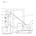
- the vibration ramming device chosen as an exemplary embodiment consists essentially of a carrier device 1, on which a vibrator (vibrator) 3 is arranged so as to be vertically displaceable via a broker 2.
- the vibrator 3 comprises a housing 31, which is surrounded by a hood 30.
- a clamping tongs 37 for receiving pile material 4 is arranged on the hood 30.
- the hood 30 serves to guide the vibrator 3 and transmits the static force of the leader 2 to the vibrator 3.
- the vibrator 3 generates via rotating imbalances 3311, 3321, 3331, 3511, 3521, 3531, a vibration which via the clamping forceps 33 on the Rammgut 4 is transmitted.
- the vibrator 3 is designed as a vibrator gearbox ( FIG. 2 ). It consists essentially of a housing 31, in which with gears 331, 332, 333, 351, 352, 353 provided shafts 33, 35 are rotatably mounted.
- the gears 331, 332, 333, 351, 352, 353 are each provided with imbalance masses 3311, 3321, 3331, 3511, 3521, 3531, wherein the gears of both shafts 33, 35 via gears 3613, 3614 of the rotor shaft 361 of a pivot motor 36 with each other are engaged.
- the gears 331, 3321, 3331, 3511, 3521, 3531 provided with unbalanced masses 331, 332, 333, 351, 352, 353 are adjustable relative to each other via the pivot motor 36 in its rotational position, whereby the resulting imbalance or the resulting static moment is adjustable.
- Such Vibratorgetriebe with rotatably mounted imbalance masses that are adjustable in relative phase position the skilled person for example from the DE 20 2007 005 283 U1 known.
- the vibrator 3 is opposite to the gears 331, 332, 333, 351, 352, 353 provided on the inside of the housing 31 each with two parallel to the circumference of the gears spaced from each other arranged inductive sensors 310.
- the inductive sensors 310 enable the detection of the angular acceleration of the rotating imbalance masses 3311, 3321, 3331, 3511, 3521, 3531.
- the time offset of the imbalance masses 3311, 3321, 3331, 3511, 3521, 3531 can furthermore be used to determine their relative position to one another.
- an acceleration sensor 311 is arranged on the housing 31 of the vibration generator 3.
- the evaluation unit is a programmable logic controller Control (PLC) 7 is arranged, which further calculated on the basis of frequency and time offset of the imbalance masses to each other the applied static moment.
- PLC programmable logic controller Control
- the shafts 33, 35 of the vibrator 3 are connected to hydraulic drives 38.
- the hydraulic drives 38 have a variable displacement.
- the PLC 7 is preceded by a memory unit 10, which is connected via lines 6 to the PLC 7.
- soil constitution specific default data sets are stored with defined operating characteristics. These default values are empirically determined quantities.
- the PLC 7 together with the memory unit 10 forms a program automatic, which selects a corresponding efficient data record depending on the existing soil condition.
- the data sets are coupled to force and acceleration values to be determined, which are transmitted as input variables of the PLC 7.
- the vibration emission of the surrounding penetrating medium is deposited as the influencing variable.
- the force and acceleration values are determined via a force sensor 52 and an acceleration sensor 311.
- the force sensor 52 is set up such that it exerts the forces acting on the pile 4, the forces applied by the leader 2 and the counterforce generated by the penetration medium results, determined and transmitted via lines 6 to the PLC 7.
- the acceleration sensor 311 is set up in such a way that it determines the penetration speed and acceleration of the pile material 4 into the penetration medium 9 and also transmits them via lines 6 to the SPS 7.
- the penetration rate can be determined with an additional sensor (53), preferably a laser for distance measurement between vibrator and soil.
- the determination of the applied force can also take place via an acceleration sensor 311 and the dynamic mass.
- a vibration sensor 54 is applied to the floor 9 at a distance from the location of penetration of the pile material 4. This vibration sensor 54 detects the vibrations emitted by the ground during the pile-driving operation from the ground 9 and transmits the detected vibration values to the PLC 7 via a line 6.
- a default data set assigned to these values is selected from a memory unit 10 whose default values are to be compared with the values set by the sensors 310 , 311 determined operating parameters are used.
- the selection of a data record by the operator of the vibratory pile driver via a corresponding control panel is possible.
- a controller 8 is arranged, which is connected via lines 6 to the memory unit 10 and to the PLC 7.
- the controller 8 is set up in such a way that it calculates the optimum operating parameters of the vibration generator from the static torque determined by the SPS 7 and the acceleration data determined by the sensors 311 against the background of the default characteristic values of the default data set selected from the memory unit 10.
- the controller 8 is connected to the arranged in the vibrator 3 pivot motor 36 for changing the relative rotational position of the imbalance masses to each other.
- the current operating characteristics recorded by the sensors 310, 311 are adapted to the corresponding preset values of the selected default data set.
- an adjustment of the resulting imbalance or the resulting static torque In case of exceeding the permissible acceleration values via the pivot motor 36 via the gear 3621 an adjustment of the resulting imbalance or the resulting static torque.
- an optical and / or acoustic signal in the operator's stand of the carrier device is possible to inform the operator of the significant exceeding of allowable acceleration values.
- this indicates the selection of an unsuitable operating characteristic quantity set from the memory unit 10. Enabling the signal instructs the operator to review and, if necessary, correct the selection of the default data set.
Claims (12)
- Vibrateur pour un appareil de fonçage vibratoire, comprenant des masselottes rotatives agencées sur des arbres, sachant que sont agencés des moyens permettant de modifier les positions de rotation relatives des masselottes, caractérisé en ce qu'un circuit de commande et de régulation est prévu présentant les composantes suivantes :- Une unité mémoire recevant des paquets de données imposés - dans laquelle il est possible de choisir le paquet respectivement nécessaire - spécifiques à la nature du sol et aux tâches à accomplir, paquets qui contiennent des paramètres d'exploitation définis,- Capteurs (5) destinés à saisir en continu les paramètres d'exploitation définis, comprenant un capteur pour saisir l'accélération des arbres en rotation dans le vibrateur (3) et/ou un capteur (51) pour saisir l'accélération du vibrateur,- Une unité d'analyse (7) servant à comparer les paramètres d'exploitation déterminés avec les paramètres d'exploitation provenant des paquets de données imposés qui ont été sélectionnés,- Un dispositif de régulation couplé à l'unité d'analyse (7) pour réguler le vibrateur sur la base des dérives des paramètres d'exploitation détectées par l'unité d'analyse (7) et via les capteurs (5) par rapport aux paramètres d'exploitation composant le paquet sélectionné de données spécifiées,- Un dispositif de commande couplé au dispositif de régulation, pour exciter les moyens servant à modifier la position relative de rotation des masselottes les unes par rapport aux autres, et- Sachant qu'est prévu un dispositif servant à sélectionner un paquet de données spécifiées sur la base des valeurs d'accélération du vibrateur détectées par les capteurs (5).
- Vibrateur selon la revendication 1, caractérisé en ce que sont agencés des capteurs (5) servant à saisir la fréquence ainsi que la position relative des masselottes les unes par rapport aux autres.
- Vibrateur selon la revendication 1 ou 2, caractérisé en ce que les capteurs (5) comprennent des capteurs et/ou des encodeurs rotatifs inductifs.
- Vibrateur selon l'une des revendications précédentes, caractérisé en ce que l'unité d'analyse (7) détermine le moment statique ponctuel sur la base des valeurs de mesure saisies par les capteurs (5, 51).
- Vibrateur selon l'une des revendications précédentes, caractérisé en ce que l'unité d'analyse (7) présente un automate programmable industriel (API).
- Vibrateur selon l'une des revendications précédentes, caractérisé en ce qu'est prévu un équipement avertisseur sonore et/ou optique pour donner l'alarme en cas d'erreurs d'entrée, équipement qui est relié à l'unité d'analyse (7).
- Vibrateur selon l'une des revendications précédentes, caractérisé en ce qu'est agencé au moins un entraînement hydraulique à volume d'absorption modifiable.
- Appareil de fonçage vibratoire comprenant un vibrateur (3) selon l'une des revendications 1 à 7, une jumelle (2) via laquelle le vibrateur (3) est agencé de manière déplaçable, et/ou un réceptacle recevant l'objet à enfoncer (4).
- Appareil de fonçage vibratoire selon la revendication 8, caractérisé en ce qu'est agencé un capteur (52) servant à saisir la force agissant sur l'objet à enfoncer (4).
- Appareil de fonçage vibratoire selon la revendication 8 ou 9, caractérisé en ce qu'est agencé un capteur (53) servant à saisir la vitesse de pénétration.
- Appareil de fonçage vibratoire selon l'une des revendications 8 à 10, caractérisé en ce qu'est prévu au moins un capteur externe (54) - qu'il est possible de fixer sur l'objet pénétrant afin de saisir les vibrations dudit objet - relié à l'unité d'analyse (7).
- Appareil de fonçage vibratoire selon l'une des revendications 9 à 11, caractérisé en ce qu'a été prévu un dispositif pour sélectionner automatiquement un paquet de données spécifié sur la base de la force déterminée agissant sur l'objet à enfoncer (4) et/ou de la vitesse et/ou de l'accélération de l'objet à enfoncer et/ou des vibrations saisies de l'objet pénétrant.
Priority Applications (2)
| Application Number | Priority Date | Filing Date | Title |
|---|---|---|---|
| EP08001600.9A EP2085148B1 (fr) | 2008-01-29 | 2008-01-29 | Vibrateur pour un appareil de fonçage vibratoire |
| US12/317,118 US7870910B2 (en) | 2008-01-29 | 2008-12-19 | Vibration generator for a vibration pile driver |
Applications Claiming Priority (1)
| Application Number | Priority Date | Filing Date | Title |
|---|---|---|---|
| EP08001600.9A EP2085148B1 (fr) | 2008-01-29 | 2008-01-29 | Vibrateur pour un appareil de fonçage vibratoire |
Publications (2)
| Publication Number | Publication Date |
|---|---|
| EP2085148A1 EP2085148A1 (fr) | 2009-08-05 |
| EP2085148B1 true EP2085148B1 (fr) | 2013-09-18 |
Family
ID=39414990
Family Applications (1)
| Application Number | Title | Priority Date | Filing Date |
|---|---|---|---|
| EP08001600.9A Active EP2085148B1 (fr) | 2008-01-29 | 2008-01-29 | Vibrateur pour un appareil de fonçage vibratoire |
Country Status (2)
| Country | Link |
|---|---|
| US (1) | US7870910B2 (fr) |
| EP (1) | EP2085148B1 (fr) |
Families Citing this family (8)
| Publication number | Priority date | Publication date | Assignee | Title |
|---|---|---|---|---|
| EP2085149B2 (fr) * | 2008-01-29 | 2021-12-22 | ABI Anlagentechnik-Baumaschinen-Industriebedarf Maschinenfabrik und Vertriebsgesellschaft mbH | Vibrateur pour un appareil de fonçage vibratoire |
| ATE531462T1 (de) * | 2009-06-26 | 2011-11-15 | Anlagentech Baumasch Ind | Schwingungserreger |
| CN102134962B (zh) * | 2010-01-26 | 2013-12-04 | 如皋市名门电气材料有限公司 | 一种自动冲孔桩机 |
| NL2005672C2 (nl) * | 2010-11-11 | 2012-05-14 | Hillcon Piling Equipment B V | Werkwijze en inrichting voor het brengen van een funderingselement in een ondergrond. |
| US9394664B2 (en) * | 2013-03-12 | 2016-07-19 | Brooke Erin Desantis | Hydraulic breaker hammer casing assembly for pile driving |
| DE102015008015A1 (de) * | 2015-06-22 | 2016-12-22 | Liebherr-Werk Nenzing Gmbh | Verfahren zum Steuern einer Vibrationsramme |
| CN105133611B (zh) * | 2015-07-11 | 2017-03-01 | 渤海大学 | 基于plc的落锤式自动打桩机控制系统 |
| DE102017001877A1 (de) * | 2017-02-27 | 2018-08-30 | Liebherr-Werk Nenzing Gmbh | Verfahren zum Erkennen von Hindernissen beim Betrieb einer Vibrationsramme |
Family Cites Families (12)
| Publication number | Priority date | Publication date | Assignee | Title |
|---|---|---|---|---|
| US3783954A (en) * | 1972-01-24 | 1974-01-08 | A Bodine | Sonic resonant driving of a column member utilizing compliant resonator element |
| US4143719A (en) * | 1976-02-27 | 1979-03-13 | Kabushiki Kaisha Komatsu Seisakusho | Multi-vibro pile hammer |
| JP2729969B2 (ja) * | 1990-03-29 | 1998-03-18 | 株式会社高橋エンジニアリング | 杭打ち装置 |
| FR2692523B1 (fr) * | 1992-06-19 | 1994-10-07 | Procedes Tech Construction | Dispositif pour la commande d'un vibrateur à moment variable. |
| US5540295A (en) * | 1995-03-27 | 1996-07-30 | Serrette; Billy J. | Vibrator for drill stems |
| US5725329A (en) * | 1996-05-08 | 1998-03-10 | Chelminski; Stephen | Method, system and apparatus for driving and pulling pilings |
| FR2772805B1 (fr) * | 1997-12-24 | 2000-02-25 | Procedes Tech Const | Dispositif pour la commande asservie de l'amplitude des vibrations d'un vibrateur a moment variable |
| DE19805448C2 (de) | 1998-02-11 | 2000-04-13 | Voith Sulzer Papiertech Patent | Verfahren und Vorrichtung zur Reinigung und Zuführung einer Papierstoffsuspension in den Stoffauflauf einer Papiermaschine |
| US5988297A (en) * | 1998-03-24 | 1999-11-23 | Hydraulic Power Systems, Inc. | Variable eccentric vibratory hammer |
| NL1008965C2 (nl) * | 1998-04-22 | 1999-10-25 | Int Construction Equipment B V | Werkwijze en inrichting voor het trillend aandrijven van een voorwerp. |
| DE202007005283U1 (de) | 2007-03-07 | 2007-07-12 | Abi Gmbh | Schwingungserreger |
| EP2085149B2 (fr) * | 2008-01-29 | 2021-12-22 | ABI Anlagentechnik-Baumaschinen-Industriebedarf Maschinenfabrik und Vertriebsgesellschaft mbH | Vibrateur pour un appareil de fonçage vibratoire |
-
2008
- 2008-01-29 EP EP08001600.9A patent/EP2085148B1/fr active Active
- 2008-12-19 US US12/317,118 patent/US7870910B2/en active Active
Also Published As
| Publication number | Publication date |
|---|---|
| US20090188687A1 (en) | 2009-07-30 |
| EP2085148A1 (fr) | 2009-08-05 |
| US7870910B2 (en) | 2011-01-18 |
Similar Documents
| Publication | Publication Date | Title |
|---|---|---|
| EP2085149B1 (fr) | Vibrateur pour un appareil de fonçage vibratoire | |
| EP2085148B1 (fr) | Vibrateur pour un appareil de fonçage vibratoire | |
| DE102015006398B3 (de) | Bodenverdichtung mit einem Baggeranbauverdichter | |
| EP2928611B1 (fr) | Procédé de réglage d'entraînement et système d'entraînement fonctionnant selon ce procédé | |
| EP3491192B1 (fr) | Rouleau de compactage du sol comprenant un dispositif de détection sur la garniture du rouleau et procédé de détermination de la rigidité du sol | |
| EP2627826B1 (fr) | Méthode pour la détermination de la rigidité et/ou de l'amortissement d'un domaine d'une solidité | |
| EP3431658A1 (fr) | Engin de compactage de sol et procédé de détermination de propriétés de terrain naturel au moyen d'un engin de compactage de sol | |
| EP3252232B2 (fr) | Compacteur et son procédé de fonctionnement | |
| DE102014001885A1 (de) | Verfahren zur Optimierung einer Betriebsfunktion einer Bodenfräsmaschine und Bodenfräsmaschine | |
| EP2984241B1 (fr) | Ensemble de battage par vibrations et procédé de fonctionnement d'un ensemble de battage par vibrations | |
| DE102010060843A1 (de) | Verfahren und Vorrichtung zum Messen von Bodenparametern mittels Verdichtungsmaschinen | |
| EP3517687A1 (fr) | Procédé de détection et de commande de compactage lors du compactage d'un sol au moyen d'un vibreur en profondeur | |
| EP2975208A2 (fr) | Engin et procédé de commande d'un engin | |
| EP2150358A1 (fr) | Générateur de vibrations pour dispositif de compactage du sol | |
| EP1722036A2 (fr) | Engin de compactage du sol | |
| EP2067533B2 (fr) | Vibrateur pour un appareil de fonçage vibratoire | |
| EP3383543B1 (fr) | Procédé pour régler un espace de concassage | |
| EP1285135A1 (fr) | Dispositif de compactage du sol avec detection des oscillations | |
| EP3589459B1 (fr) | Robot à bras articulé et procédé d'usinage par enlèvement de copeaux d'une pièce au moyen du robot à bras articulé | |
| DE102018001505A1 (de) | Verfahren zum spanenden Bearbeiten eines Werkstückes mittels einem Knickarmroboter | |
| EP2628391B1 (fr) | Procédé de remplissage de saucisses avec une masse pâteuse et machine de remplissage destinée à l'exécution de ce procédé | |
| DE10220057B4 (de) | Vorrichtung zur Kompensation von durch Massenkräfte verursachten Schwingungen | |
| EP3819434B1 (fr) | Procédé et dispositif de fraisage de paroi de fente permettant de créer une fente fraisée dans le sol | |
| WO2017045918A1 (fr) | Procédé de fonctionnement d'un broyeur tubulaire, ensemble permettant de déterminer des données caractéristiques d'un broyeur tubulaire et broyeur tubulaire | |
| DE19631992B4 (de) | Vibrationsbär mit Steuervorrichtung |
Legal Events
| Date | Code | Title | Description |
|---|---|---|---|
| PUAI | Public reference made under article 153(3) epc to a published international application that has entered the european phase |
Free format text: ORIGINAL CODE: 0009012 |
|
| 17P | Request for examination filed |
Effective date: 20081104 |
|
| AK | Designated contracting states |
Kind code of ref document: A1 Designated state(s): AT BE BG CH CY CZ DE DK EE ES FI FR GB GR HR HU IE IS IT LI LT LU LV MC MT NL NO PL PT RO SE SI SK TR |
|
| AX | Request for extension of the european patent |
Extension state: AL BA MK RS |
|
| AKX | Designation fees paid |
Designated state(s): AT DE FR GB NL |
|
| 17Q | First examination report despatched |
Effective date: 20101022 |
|
| GRAP | Despatch of communication of intention to grant a patent |
Free format text: ORIGINAL CODE: EPIDOSNIGR1 |
|
| INTG | Intention to grant announced |
Effective date: 20130522 |
|
| GRAS | Grant fee paid |
Free format text: ORIGINAL CODE: EPIDOSNIGR3 |
|
| GRAA | (expected) grant |
Free format text: ORIGINAL CODE: 0009210 |
|
| AK | Designated contracting states |
Kind code of ref document: B1 Designated state(s): AT DE FR GB NL |
|
| REG | Reference to a national code |
Ref country code: GB Ref legal event code: FG4D Free format text: NOT ENGLISH |
|
| REG | Reference to a national code |
Ref country code: AT Ref legal event code: REF Ref document number: 632444 Country of ref document: AT Kind code of ref document: T Effective date: 20131015 |
|
| REG | Reference to a national code |
Ref country code: DE Ref legal event code: R096 Ref document number: 502008010662 Country of ref document: DE Effective date: 20131114 |
|
| REG | Reference to a national code |
Ref country code: NL Ref legal event code: T3 |
|
| REG | Reference to a national code |
Ref country code: DE Ref legal event code: R026 Ref document number: 502008010662 Country of ref document: DE |
|
| PLBI | Opposition filed |
Free format text: ORIGINAL CODE: 0009260 |
|
| PLAX | Notice of opposition and request to file observation + time limit sent |
Free format text: ORIGINAL CODE: EPIDOSNOBS2 |
|
| 26 | Opposition filed |
Opponent name: BAUER MASCHINEN GMBH Effective date: 20140618 |
|
| REG | Reference to a national code |
Ref country code: DE Ref legal event code: R026 Ref document number: 502008010662 Country of ref document: DE Effective date: 20140618 |
|
| PLBB | Reply of patent proprietor to notice(s) of opposition received |
Free format text: ORIGINAL CODE: EPIDOSNOBS3 |
|
| REG | Reference to a national code |
Ref country code: FR Ref legal event code: PLFP Year of fee payment: 9 |
|
| REG | Reference to a national code |
Ref country code: DE Ref legal event code: R100 Ref document number: 502008010662 Country of ref document: DE |
|
| PLCK | Communication despatched that opposition was rejected |
Free format text: ORIGINAL CODE: EPIDOSNREJ1 |
|
| PLBN | Opposition rejected |
Free format text: ORIGINAL CODE: 0009273 |
|
| STAA | Information on the status of an ep patent application or granted ep patent |
Free format text: STATUS: OPPOSITION REJECTED |
|
| 27O | Opposition rejected |
Effective date: 20160419 |
|
| REG | Reference to a national code |
Ref country code: FR Ref legal event code: PLFP Year of fee payment: 10 |
|
| REG | Reference to a national code |
Ref country code: FR Ref legal event code: PLFP Year of fee payment: 11 |
|
| PGFP | Annual fee paid to national office [announced via postgrant information from national office to epo] |
Ref country code: GB Payment date: 20220125 Year of fee payment: 15 |
|
| PGFP | Annual fee paid to national office [announced via postgrant information from national office to epo] |
Ref country code: FR Payment date: 20230123 Year of fee payment: 16 Ref country code: AT Payment date: 20230118 Year of fee payment: 16 |
|
| PGFP | Annual fee paid to national office [announced via postgrant information from national office to epo] |
Ref country code: DE Payment date: 20221230 Year of fee payment: 16 |
|
| P01 | Opt-out of the competence of the unified patent court (upc) registered |
Effective date: 20230513 |
|
| PGFP | Annual fee paid to national office [announced via postgrant information from national office to epo] |
Ref country code: NL Payment date: 20230124 Year of fee payment: 16 |
|
| GBPC | Gb: european patent ceased through non-payment of renewal fee |
Effective date: 20230129 |
|
| PG25 | Lapsed in a contracting state [announced via postgrant information from national office to epo] |
Ref country code: GB Free format text: LAPSE BECAUSE OF NON-PAYMENT OF DUE FEES Effective date: 20230129 |
|
| PGFP | Annual fee paid to national office [announced via postgrant information from national office to epo] |
Ref country code: NL Payment date: 20240123 Year of fee payment: 17 |
|
| PGFP | Annual fee paid to national office [announced via postgrant information from national office to epo] |
Ref country code: AT Payment date: 20240118 Year of fee payment: 17 |