EP2085065A2 - Foot support for a patient support - Google Patents
Foot support for a patient support Download PDFInfo
- Publication number
- EP2085065A2 EP2085065A2 EP09006535A EP09006535A EP2085065A2 EP 2085065 A2 EP2085065 A2 EP 2085065A2 EP 09006535 A EP09006535 A EP 09006535A EP 09006535 A EP09006535 A EP 09006535A EP 2085065 A2 EP2085065 A2 EP 2085065A2
- Authority
- EP
- European Patent Office
- Prior art keywords
- foot
- support
- patient support
- arm
- light source
- Prior art date
- Legal status (The legal status is an assumption and is not a legal conclusion. Google has not performed a legal analysis and makes no representation as to the accuracy of the status listed.)
- Granted
Links
Images


Classifications
-
- A—HUMAN NECESSITIES
- A61—MEDICAL OR VETERINARY SCIENCE; HYGIENE
- A61G—TRANSPORT, PERSONAL CONVEYANCES, OR ACCOMMODATION SPECIALLY ADAPTED FOR PATIENTS OR DISABLED PERSONS; OPERATING TABLES OR CHAIRS; CHAIRS FOR DENTISTRY; FUNERAL DEVICES
- A61G7/00—Beds specially adapted for nursing; Devices for lifting patients or disabled persons
- A61G7/05—Parts, details or accessories of beds
-
- A—HUMAN NECESSITIES
- A61—MEDICAL OR VETERINARY SCIENCE; HYGIENE
- A61G—TRANSPORT, PERSONAL CONVEYANCES, OR ACCOMMODATION SPECIALLY ADAPTED FOR PATIENTS OR DISABLED PERSONS; OPERATING TABLES OR CHAIRS; CHAIRS FOR DENTISTRY; FUNERAL DEVICES
- A61G13/00—Operating tables; Auxiliary appliances therefor
- A61G13/0009—Obstetrical tables or delivery beds
-
- A—HUMAN NECESSITIES
- A61—MEDICAL OR VETERINARY SCIENCE; HYGIENE
- A61G—TRANSPORT, PERSONAL CONVEYANCES, OR ACCOMMODATION SPECIALLY ADAPTED FOR PATIENTS OR DISABLED PERSONS; OPERATING TABLES OR CHAIRS; CHAIRS FOR DENTISTRY; FUNERAL DEVICES
- A61G13/00—Operating tables; Auxiliary appliances therefor
- A61G13/10—Parts, details or accessories
- A61G13/12—Rests specially adapted therefor; Arrangements of patient-supporting surfaces
-
- A—HUMAN NECESSITIES
- A61—MEDICAL OR VETERINARY SCIENCE; HYGIENE
- A61G—TRANSPORT, PERSONAL CONVEYANCES, OR ACCOMMODATION SPECIALLY ADAPTED FOR PATIENTS OR DISABLED PERSONS; OPERATING TABLES OR CHAIRS; CHAIRS FOR DENTISTRY; FUNERAL DEVICES
- A61G13/00—Operating tables; Auxiliary appliances therefor
- A61G13/10—Parts, details or accessories
- A61G13/101—Clamping means for connecting accessories to the operating table
-
- A—HUMAN NECESSITIES
- A61—MEDICAL OR VETERINARY SCIENCE; HYGIENE
- A61G—TRANSPORT, PERSONAL CONVEYANCES, OR ACCOMMODATION SPECIALLY ADAPTED FOR PATIENTS OR DISABLED PERSONS; OPERATING TABLES OR CHAIRS; CHAIRS FOR DENTISTRY; FUNERAL DEVICES
- A61G13/00—Operating tables; Auxiliary appliances therefor
- A61G13/10—Parts, details or accessories
- A61G13/12—Rests specially adapted therefor; Arrangements of patient-supporting surfaces
- A61G13/1205—Rests specially adapted therefor; Arrangements of patient-supporting surfaces for specific parts of the body
- A61G13/121—Head or neck
-
- A—HUMAN NECESSITIES
- A61—MEDICAL OR VETERINARY SCIENCE; HYGIENE
- A61G—TRANSPORT, PERSONAL CONVEYANCES, OR ACCOMMODATION SPECIALLY ADAPTED FOR PATIENTS OR DISABLED PERSONS; OPERATING TABLES OR CHAIRS; CHAIRS FOR DENTISTRY; FUNERAL DEVICES
- A61G13/00—Operating tables; Auxiliary appliances therefor
- A61G13/10—Parts, details or accessories
- A61G13/12—Rests specially adapted therefor; Arrangements of patient-supporting surfaces
- A61G13/1205—Rests specially adapted therefor; Arrangements of patient-supporting surfaces for specific parts of the body
- A61G13/1245—Knees, upper or lower legs
-
- A—HUMAN NECESSITIES
- A61—MEDICAL OR VETERINARY SCIENCE; HYGIENE
- A61G—TRANSPORT, PERSONAL CONVEYANCES, OR ACCOMMODATION SPECIALLY ADAPTED FOR PATIENTS OR DISABLED PERSONS; OPERATING TABLES OR CHAIRS; CHAIRS FOR DENTISTRY; FUNERAL DEVICES
- A61G13/00—Operating tables; Auxiliary appliances therefor
- A61G13/10—Parts, details or accessories
- A61G13/12—Rests specially adapted therefor; Arrangements of patient-supporting surfaces
- A61G13/1205—Rests specially adapted therefor; Arrangements of patient-supporting surfaces for specific parts of the body
- A61G13/125—Ankles or feet
-
- A—HUMAN NECESSITIES
- A61—MEDICAL OR VETERINARY SCIENCE; HYGIENE
- A61G—TRANSPORT, PERSONAL CONVEYANCES, OR ACCOMMODATION SPECIALLY ADAPTED FOR PATIENTS OR DISABLED PERSONS; OPERATING TABLES OR CHAIRS; CHAIRS FOR DENTISTRY; FUNERAL DEVICES
- A61G13/00—Operating tables; Auxiliary appliances therefor
- A61G13/10—Parts, details or accessories
- A61G13/12—Rests specially adapted therefor; Arrangements of patient-supporting surfaces
- A61G13/128—Rests specially adapted therefor; Arrangements of patient-supporting surfaces with mechanical surface adaptations
- A61G13/1285—Rests specially adapted therefor; Arrangements of patient-supporting surfaces with mechanical surface adaptations having modular surface parts, e.g. being replaceable or turnable
-
- Y—GENERAL TAGGING OF NEW TECHNOLOGICAL DEVELOPMENTS; GENERAL TAGGING OF CROSS-SECTIONAL TECHNOLOGIES SPANNING OVER SEVERAL SECTIONS OF THE IPC; TECHNICAL SUBJECTS COVERED BY FORMER USPC CROSS-REFERENCE ART COLLECTIONS [XRACs] AND DIGESTS
- Y10—TECHNICAL SUBJECTS COVERED BY FORMER USPC
- Y10S—TECHNICAL SUBJECTS COVERED BY FORMER USPC CROSS-REFERENCE ART COLLECTIONS [XRACs] AND DIGESTS
- Y10S5/00—Beds
- Y10S5/905—Beds with light emitting means
Definitions
- the arm coupler 132 of bracket 122 is C-shaped and includes spaced-apart end surfaces 140, 142, a substantially circular-shaped outer surface 144 extending between end surfaces 140, 142, and seven distinct, separate inner surfaces 146, 148, 150, 152, 154, 156, 158 extending between end surfaces 140, 142.
- Five of the inner surfaces 146, 148, 150, 152, 154 define a hexagonal-shaped opening 160 in which arm 126 is placed to couple arm 126 to bracket 122.
- the power cord 128 includes a power line 178 having a first end (not shown) coupled to light source 124 and a second end 180 and a coupler or plug 182 coupled to second end 180 of power line 178.
- the power line 178 extends from light source 124, through arm 126 and bracket 122, to coupler 182.
- the hexagonal-shaped member 162 of arm 126 is positioned in hexagonal-shaped opening 160 formed in the bracket 122 and the power line 178 is pushed through the slot 164 formed in bracket 122 so that the power line 178 extends through the hexagonal-shaped opening 160 defined in arm coupler 132 of bracket 122.
- the arm 126 of light assembly 120 passes through the slot 198 and is releasably retained by the arms 194 and 196.
- the light assembly 120 may be releasably coupled to foot section by other retaining members.
- the light source 120 may be coupled to the foot section 20 by a single clip, one or more hook and loop fasteners, one or more clamps, or a combination of conventional retaining members.
- FIG. 11 An alternative embodiment hospital bed 10' is illustrated in Fig. 11 as including a frame 12 supporting a patient support.
- the patient support includes a head portion 14, a seat portion 16, and a foot portion 18.
- the foot portion 18 includes a foot section 20, foot supports 22, 24, and calf supports 226, 228 as shown in Figs. 11 and 12 .
- the hospital bed 10' is a birthing bed
- foot section 20 is selectively removable from the remainder of hospital bed 10' to provide access to a patient on bed 10' as shown in Fig. 12 .
- the foot supports 22, 24 and calf supports 226, 228 are positioned under or below foot section 20 as shown in Fig. 11 . Removal of the foot section 20 exposes the foot supports 22, 24 and calf supports 226, 228 as shown in Fig. 12 .
- the arm 452 includes a head 460 and a rod 462 that is coupled to head 460 and positioned in sleeve 456 of foot support coupler 450. Except for head 460 and rod 462, all other portions of arm 452 are identical to arm 244 of calf supports 226, 228.
- the rod 462 includes first and second apertures 464, 466 that cooperate with detent 458 to lock the arm 452 relative to the foot support 22, 24 in a storage position and a use position. In alternative embodiments, the rod 462 may include additional apertures to provide additional positions wherein the arm 452 may be locked relative to the foot support 22, 24.
- the patient support 10' further includes a support surface 360, an actuator 362, and a release system or CPR release 364, as shown in Fig. 20 .
- the support surface 360 extends over the head, seat, and foot portions 14, 16, 18 of the patient support 10' as shown in Fig. 1 . In the illustrated embodiment, these head, seat, and foot portions 14, 16, 18 of support surface 360 are movable relative to each other.
- the release system 364 may be used in the event that a patient on support surface 360 of hospital bed 10 goes into cardiac arrest to rapidly lower the head portion 14 of patient support 360. In preferred embodiments, the release system 364 lowers the head portion 14 of patient support 360 quicker than the other controls discussed above.
Landscapes
- Health & Medical Sciences (AREA)
- Public Health (AREA)
- Life Sciences & Earth Sciences (AREA)
- Animal Behavior & Ethology (AREA)
- General Health & Medical Sciences (AREA)
- Veterinary Medicine (AREA)
- Biomedical Technology (AREA)
- Engineering & Computer Science (AREA)
- Gynecology & Obstetrics (AREA)
- Nursing (AREA)
- Accommodation For Nursing Or Treatment Tables (AREA)
- Invalid Beds And Related Equipment (AREA)
- Orthopedics, Nursing, And Contraception (AREA)
- Devices For Medical Bathing And Washing (AREA)
Abstract
Description
- The present invention relates to patient supports such as hospital beds, carts, chairs, and stretchers. More particularly, the present invention relates to foot portions and to support surface release systems of patient supports.
- Hospital beds and other patient supports are often provided with laterally spaced adjustable foot supports positioned proximate a seat section. The seat section and the foot supports are configured to define a central opening therebetween. An example of such a patient support is disclosed in detail in
U.S. Patent No. 6,226,821 , which is assigned to the assignee of the present invention and is expressly incorporated by reference herein. - While such prior art patient supports provide caregivers with improved access to a patient's pelvic region, there remains a need for improvements to conventional foot supports. More particularly, there is a need for foot supports including improved adjustment mechanisms. There is a further need for foot supports providing increased visibility of the patient's pelvic region.
- The patient support or bed of the present invention includes a frame supporting a patient support including a head portion, a seat portion, and a foot portion, wherein the seat portion is positioned intermediate the head portion and the foot portion. The foot portion includes a foot section and laterally spaced foot supports. The foot supports are configured for a first movement about a substantially vertical axis and a second movement about a substantially horizontal axis. Each foot support includes first and second frame sections, a flexible housing section extending between the frame sections, a foot panel coupled to the second frame section, a handle coupled to the second frame section, and a position adjustment mechanism. The position adjustment mechanism facilitates movement of the foot panel relative to the frame about the substantially vertical axis and the substantially horizontal axis.
- The position adjustment mechanism includes a handle, first and second clutches, first and second linkages extending between the handle and the first and second clutches, respectively, and a spring for biasing the second frame section upwardly about the substantially horizontal axis.
- The clutches may be positioned in an engaged position wherein relative movement of the foot panel and the frame is not permitted and a disengaged position wherein relative movement is permitted. Moving the handle in a first direction about a pivot axis moves the first and second linkages which, in turn, moves the first and second clutches from their engaged positions to their disengaged positions.
- A light assembly is coupled to at least one of the foot supports. The light assembly includes a base bracket, a light source, an arm extending between the base bracket and the light source, and a power cord. The base bracket includes a base and an arm coupler that receives and releasably holds the arm. The arm includes a flexible portion and a universal joint coupling a light housing to the flexible portion.
- The foot portion includes a removable foot section having an upper surface that faces upwardly toward a patient lying on the foot portion, and a lower or storage surface facing downwardly away from the patient. Retainers are coupled to storage surface and are configured to releasably retain the arm of the light assembly.
- In a further embodiment of the patient support of the present invention, calf supports are coupled to the foot supports to move with and relative to the foot supports. Each calf support includes a foot support coupler, an arm, a calf holder, and a calf holder coupler positioned intermediate the calf holder and the arm. The arm and the calf holder of the calf supports are movable relative to the foot supports about a pivot axis between a storage position and a use position. A detent interacts with a rod supporting the calf holder through the arm to control movement thereof. Moreover, the arm is locked in position relative to the foot support coupler in the storage and use positions by the interaction of the detent and apertures formed in the rod.
- In a further embodiment of the patient support of the present invention, an actuator is provided to move the head portion between raised and lowered positions relative to the seat portion. A release system interacts with the actuator to provide another mechanism in order to lower the head portion. The release system includes an actuator coupler, first and second handles, first and second cables extending between the actuator coupler and the first and second handles, respectively, and first and second springs. The actuator includes a release switch and the actuator coupler is coupled to this release switch. Actuation of the release switch releases the force exerted by the actuator on the head portion so that the head portion may move from its raised position to its lowered position.
- Additional features of the disclosure will become apart to those skilled in the art upon consideration of the following detailed description when taken in conjunction with the accompanying drawings.
- The detailed description particularly refers to the accompanying figures in which:
-
Fig. 1 is a perspective view of a patient support having a head section, a seat section, a foot section, and two foot supports positioned under the foot section; -
Fig. 2 is a perspective view similar toFig. 1 showing the foot section removed to expose the foot supports and that the foot supports are movable; -
Fig. 3 is a perspective view of one of the foot supports showing a light source coupled to the foot support; -
Fig 4 . is a bottom plan view of the foot support ofFig. 3 , with a housing of the foot support removed for clarity, showing a position adjustment mechanism of the foot support; -
Fig. 5 is a bottom plan view similar toFig. 4 showing the foot support being movable between first (phantom lines) and second (solid lines) rotational positions; -
Fig. 6 is a side elevation view of the foot support showing the foot support in a substantially horizontal position; -
Fig. 7 is a side elevation view similar toFig. 6 showing a portion of the foot support being movable between substantially horizontal (phantom lines) and raised (solid lines) positions; -
Fig. 8 is an exploded perspective view of a portion of the foot support and a portion of the light source; -
Fig. 9 is a cross-sectional view taken along line 9-9 ofFig. 8 , illustrating the arm inserted into the bracket; -
Fig. 10 is an elevation view of the light source coupled to a storage surface of the foot section of the bed; -
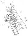
Fig. 11 is a perspective view of an alternative embodiment patient support having a head portion, a seat portion, and a foot portion, the foot portion including a foot section and two foot supports positioned under the foot section; -
Fig. 12 is a perspective view similar toFig. 11 showing the foot section removed to expose the foot supports and the patient support further including a calf support positioned under each foot support; -
Fig. 13 is a perspective view similar toFig.12 showing each of the foot supports being rotated outwardly about a substantially vertical axis and upwardly about a substantially horizontal axis; -
Fig. 14 is a perspective view of one of the calf supports ofFig. 13 showing the calf support including a foot support coupler, a calf holder, an arm extending from the foot support coupler toward the calf holder, and another coupler positioned between the arm and the calf holder and the arm and calf holder of the calf support being movable between a storage position (phantom lines) and a use position (solid lines); -
Fig. 15 is an exploded perspective view of the foot support coupler and a portion of the arm of the calf support; -
Fig. 16 is a perspective view similar toFig 14 showing the calf holder of the calf support being rotated from a storage position (phantom lines) to a use position (solid lines); -
Fig. 17 is an elevational view, with portions cutaway, of the coupler and portions of the arm and calf holder showing the coupler coupling the arm to the calf holder; -
Fig. 18 is a perspective view similar toFig. 13 showing the calf supports in their use position; -
Fig. 19 is a perspective view, similar toFig. 15 , of an alternative foot support coupler and a portion of the arm of the calf support; -
Fig. 20 is a perspective view, with portions cutaway, of the patient support shown inFig. 11 showing the patient support including a frame, a support surface, and a release system; -
Fig. 21 is a perspective view of a portion of the release system ofFig. 20 ; and -
Fig. 22 is a perspective view, with portions cutaway, similar toFig. 20 , showing the release system being actuated to lower the head portion of the support surface. - A
hospital bed 10 including aframe 12 supporting a patient support including ahead portion 14, aseat portion 16, and afoot portion 18, is shown inFig. 1 . Thehead portion 14 is spaced apart fromfoot portion 18 byseat portion 16. As described in greater detail below, theportions foot portion 18 includes afoot section 20 and laterally spaced apart foot supports 22, 24, as shown inFigs. 1 and2 . In the illustrated embodiment, thehospital bed 10 is a birthing bed, andfoot section 20 is selectively removable from the remainder ofhospital bed 10 to provide access to a patient onbed 10 as shown inFig. 2 . When thefoot section 20 is coupled to the remainder ofbed 10, the foot supports 22, 24 are positioned under or belowfoot section 20 as shown inFig. 1 . Removal of thefoot section 20 exposes the foot supports 22, 24 as shown inFig. 2 . - The foot supports 22, 24 are movable about a substantially
vertical axis 26 indirections horizontal axis 32 indirections Fig. 2 , so that the foot supports 22, 24 may be placed in a desired position. Eachfoot support second frame sections flexible housing section 42 extending betweenframe sections foot panel 44 coupled tosecond frame section 40, ahandle 46 coupled tosecond frame section 40, andposition adjustment mechanism 48. Thefoot panel 44 is formed to include arecess 50 sized and shaped to receive a patient's foot. - The
position adjustment mechanism 48permits foot panel 44 to move relative to frame 12 aboutaxes directions foot panel 44 may be positioned to receive a patient's foot inrecess 50. As shown inFig. 4 , theposition adjustment mechanism 48 includes ahandle 52, first andsecond clutches second linkages handle 52 and first andsecond clutches spring 62. - The
clutches foot panel 44 andframe 12 is not permitted and a disengaged position wherein relative movement is permitted. For example, when first clutch 54 is disengaged, thefoot panel 44 is permitted to move relative to frame 12 about thevertical axis 26, as shown inFigs. 4 and5 , and when the second clutch 56 is disengaged,foot panel 44 is permitted to move relative to theframe 12 about thehorizontal axis 32 as shown inFigs. 6 and7 . - To move the
clutches handle 52 ofposition adjustment mechanism 48 in directions 64, 66 about apivot axis 68. As previously mentioned, handle 52 is coupled to the first andsecond linkages second clutches clutches handle 52 must be moved by the caregiver in direction 64 to disengage theclutches handle 52 in direction 64 aboutpivot axis 68 moves thelinkages clutches handle 52 of theposition adjustment mechanism 48 is positioned adjacent to handle 46 offoot support handles clutches foot support directions axes - Each of these
clutches clamp 70 and arod 72 that extends throughclamp 70 as shown inFig. 4 . Theclamp 70 is movable between an engaged position wherein theclamp 70 interacts with therod 72 to prevent therod 72 from moving through theclamp 70 and a disengaged position wherein therod 72 is permitted to move through theclamp 70. Thus, therod 72 is movable relative to theclamp 70 when theclamp 70 is in its disengaged position. - To permit movement of the
foot support directions vertical axis 26, theclamp 70 of first clutch 54 is coupled to frame 12 and therod 72 of first clutch 54 is coupled to thefirst frame section 38 offoot support first frame section 38 of eachfoot support rod support 74 and an end of therod 72 of first clutch 54 is pivotally coupled torod support 74. - The
clamp 70 of first clutch 54 is coupled to frame 12 by portions offoot support foot support bushing 76 and aclamp support 78 coupled tobushing 76. Theframe 12 ofbed 10 includes apost 80 that extends vertically upward through anaperture 82 formed inbushing 76 as shown inFigs. 1-5 . Thefoot support post 80 and thus post 80 definesvertical axis 26. As shown inFigs. 4 and5 , thebushing 76 includes a keyway orslot 84 and thepost 80 includes a key 86 that is positioned inslot 84 to fix the rotational position of thebushing 76 and clampsupport 78 relative to theframe 12. Theclamp 70 is pivotally coupled to clampsupport 78 to permit pivoting of theclamp 70 relative to frame 12. - When the first clutch 54 is in the engaged position, the
foot panel 44 is prevented from rotating indirections vertical axis 26 defined bypost 80. This rotation is prevented because the position of therod 72 is fixed relative to the position of theclamp 70. To move thefoot panel 44 aboutvertical axis 26, the first clutch 54 is moved to its disengaged position so therod 72 and thus all portions offoot support support 78 are permitted to move relative to theclamp 70 andframe 12. When the first clutch 54 is in its disengaged position and the user movesfoot support vertical axis 26 indirections rod 72 travels through and relative to clamp 70 along an axial path. Theclamp 70 is rotatably coupled to clampsupport 78 to pivot about avertical axis 88 that is parallel tovertical axis 26 defined bypost 80. When the first clutch 54 is disengaged and the caregiver movesfoot support vertical axis 26 indirections clamp 70 rotates about thisvertical axis 88 to permit therod 72 to rotate and travel axially throughclamp 70. - The second clutch 56 is similarly movable between an engaged position and a disengaged position to prevent or permit, respectively, relative movement of the first and
second frame sections directions horizontal axis 32 as shown inFigs. 6 and7 . Similar to the arrangement of the first clutch 54, the second clutch 56 has itsrod 72 coupled to thefirst frame section 38 and itsclamp 70 coupled to thesecond frame section 40. Thefirst frame section 38 includes arod support 90 pivotally coupled torod 72 of second clutch 56 and thesecond frame section 40 includes aclamp support 91 pivotally coupled to clamp 70 of second clutch 56. Apivot pin 92 pivotally couples an end ofrod 72 torod support 90 so thatrod 72 may pivot about apivot axis 94 defined bypivot pin 92. When the second clutch 56 is in its disengaged position, therod 72 is movable through theclamp 70 to permit thesecond frame section 40 to rotate indirections horizontal axis 32 relative tofirst frame section 38 and when the clutch 56 is in its engaged position, this movement is not permitted. Therod 72 travels axially through and relative to clamp 70 and pivots about apivot axis 94 as thesecond frame section 40 is rotated abouthorizontal axis 32. - In the illustrated embodiment, the first and
second clutches linkages handle 46 toclutches - The
spring 62 is configured to assist the caregiver in moving thesecond frame section 40 upwardly indirection 34 abouthorizontal axis 32. Thus, when the cargeiver moves handle 52 to disengage second clutch 56, thespring 62 biases thesecond frame section 40 upwardly indirection 34. This biasing force provided by thespring 62 compensates for the weight of thesecond frame section 40 and any force or weight generated by a patient's foot positioned infoot support foot support direction 36, the caregiver must move thefoot support spring 62. However, the caregiver is assisted in moving against the biasing force by the weight of thesecond frame section 40 and possibly a force and/or weight from a patient's foot. - In the illustrated embodiment, the
spring 62 is a gas spring having acylinder 96 pivotally coupled tosecond frame section 40 and apiston 98 pivotally coupled tofirst frame section 38 as shown inFigs. 4 and5 . Thegas spring 62 is configured to biaspiston 98 away fromcylinder 96 indirection 110 to assist the caregiver in raisingsecond frame section 40 as discussed above. In alternative embodiments other devices such as a coil spring can be used to assist a caregiver in raising the second frame section relative to the first frame section. - Referring further to
Fig. 3 , theflexible housing section 42 includes abellows portion 112 extending between the first andsecond frame sections cover portion 114 that covers thefirst frame section 38. Whensecond frame section 40 is moved relative tofirst frame section 38, theflexible housing section 42 expands and contracts to maintain a continuous housing for theclutches spring 62, andlinkages flexible housing section 42 cooperates with the first andsecond frame sections clutches spring 62, andlinkages - The
hospital bed 10 further includes alight assembly 120 coupled tofoot support 22 as shown inFigs. 2 and3 . Thelight assembly 120 includes abase bracket 122, alight source 124, anarm 126 extending betweenbase bracket 122 andlight source 124, and apower cord 128. Thebase bracket 122 includes abase 130 andarm coupler 132 that receives and holdsarm 126. Thebase 130 includes first andsecond apertures second frame section 40 offoot support 22 by screws orcouplers 138 extending throughapertures Figs. 3 and8 . Thesesame screws 138 couple handle 46 tosecond frame section 40. To installbracket 122, thescrews 138 are removed, thebracket 122 is positioned betweenhandle 46 andsecond frame section 40, and thescrews 138 are threaded throughhandle 46 andapertures bracket 122 and intosecond frame section 40. In alternative embodiments, thebase 130 includes first and second slots (not shown) and thebracket 122 is installed by loosening thescrews 138 instead of removing thescrews 138, sliding thebracket 122 between thehandle 46 andsecond frame section 40 so that the screws 13 8 are received in the slots, and then tightening the screws 13 8. - Referring now to
Figs. 8 and 9 , thearm coupler 132 ofbracket 122 is C-shaped and includes spaced-apart end surfaces 140, 142, a substantially circular-shapedouter surface 144 extending between end surfaces 140, 142, and seven distinct, separateinner surfaces inner surfaces opening 160 in which arm 126 is placed tocouple arm 126 tobracket 122. Thearm 126 includes a hexagonal-shapedmember 162 that is sized and shaped to extend into, be positioned within, and mate with hexagonal-shapedopening 160 ofbracket 122 to couplearm 126 andbracket 122 as shown inFigs. 3 ,8 and 9 .
The other twoinner surfaces slot 164 that communicates with hexagonal-shapedopening 160. In the illustrated embodiment, both theslot 164 and hexagonal-shapedopening 160 extend fromend surface 140 to endsurface 142. In alternative embodiments, thearm coupler 132 may define an opening having any shape and thearm 126 may include a member sized and shaped to be positioned within the opening to couple thearm 126 andbracket 122. In other alternative embodiments, thearm coupler 132 may be any structure that receives and holds thearm 126. For example, thearm coupler 132 may include resilient first and second portions that are movable relative to each other and that cooperate to define an opening. When thearm 126 is positioned in the opening, the first and second portions initially expand to receive thearm 126 and then compress thearm 126 to couple thearm 126 to thebracket 122. - With reference to
Figs. 3 and10 , thelight source 124 includes a light 166, alight housing 168, ahandle 170 coupled to thehousing 168, and apower switch 172 coupled tohousing 168. In the illustrated embodiment, thearm 126 includes a flexible link orportion 174 and auniversal joint 176 coupling thelight housing 168 to theflexible portion 174. Theflexible portion 174 anduniversal joint 176 permit a caregiver to grab handle 170 oflight source 124 and move thelight source 124 to a desired position and orientation. The combination of theflexible portion 174 anduniversal joint 176 gives thearm 126 six degrees of freedom. In alternative embodiments, the arm may include any number of rigid and flexible links, joints, etc. to provide the arm with any number of degrees of freedom so that the light source may be positioned in a desired location and/or orientation. - The
power cord 128 includes apower line 178 having a first end (not shown) coupled tolight source 124 and asecond end 180 and a coupler or plug 182 coupled tosecond end 180 ofpower line 178. Thepower line 178 extends fromlight source 124, througharm 126 andbracket 122, tocoupler 182. When thearm 126 is coupled tobracket 122, the hexagonal-shapedmember 162 ofarm 126 is positioned in hexagonal-shapedopening 160 formed in thebracket 122 and thepower line 178 is pushed through theslot 164 formed inbracket 122 so that thepower line 178 extends through the hexagonal-shapedopening 160 defined inarm coupler 132 ofbracket 122. - The
hospital bed 10 further includes apower supply 184 coupled toseat portion 16 ofbed 10 as shown inFigs. 3 . The coupler or plug 182 ofpower cord 128 is plugged into thispower supply 184 to provide power tolight source 124. In the preferred embodiment, thepower supply 184 includes ahousing 186 and a jack (not shown) within thehousing 186. In alternative embodiments, the plug of the power cord may be connected to other sources of power including those remote from thebed 10. - When the
light assembly 120 is not in use, the caregiver may store thelight assembly 120 within a storage area 187 positioned on the underside of theremovable foot section 20 ofbed 10. Thefoot section 20 includes anupper surface 188 that faces upwardly toward a patient lying onfoot section 20, a lower orstorage surface 190 facing downwardly away from the patient, and retaining members, such as clips orcouplers 192, coupled to thelower surface 190. Theclips 192 are configured to releasably receive and holdarm 126 oflight assembly 120. In the illustrated embodiment, thecouplers 192 are resilient clips that snap overarm 126 oflight assembly 120. Theclips 192 may comprise opposing first andsecond arms slot 198. In operation, thearm 126 oflight assembly 120 passes through theslot 198 and is releasably retained by thearms light assembly 120 may be releasably coupled to foot section by other retaining members. For example, thelight source 120 may be coupled to thefoot section 20 by a single clip, one or more hook and loop fasteners, one or more clamps, or a combination of conventional retaining members. - An alternative embodiment hospital bed 10' is illustrated in
Fig. 11 as including aframe 12 supporting a patient support. The patient support includes ahead portion 14, aseat portion 16, and afoot portion 18. Thefoot portion 18 includes afoot section 20, foot supports 22, 24, and calf supports 226, 228 as shown inFigs. 11 and12 . In the illustrated embodiment, the hospital bed 10' is a birthing bed, andfoot section 20 is selectively removable from the remainder of hospital bed 10' to provide access to a patient on bed 10' as shown inFig. 12 . When thefoot section 20 is coupled to the remainder of bed 10', the foot supports 22, 24 and calf supports 226, 228 are positioned under or belowfoot section 20 as shown inFig. 11 . Removal of thefoot section 20 exposes the foot supports 22, 24 and calf supports 226, 228 as shown inFig. 12 . - The foot supports 22, 24 are movable about a substantially
vertical axis 26 indirections horizontal axis 32 indirections Fig. 13 , so that the foot supports 22, 24 may be placed in a desired position. The foot supports 22, 24 are identical to those described above in detail with respect toFigs. 1-7 . - The calf supports 226, 228 are coupled to one of the laterally spaced opposing side edges 227 and 229 of the foot supports 22, 24, respectively (
Figs. 14 and16 ). Alongitudinal axis 231 of eachfoot support Fig. 13 , the calf supports 226, 228 move with the foot supports 22, 24 as the foot supports 22, 24 are moved about the vertical andhorizontal axes Fig. 13 and a use position shown inFig. 18 . - Each
calf support foot support coupler 242, anarm 244, acalf holder 246, and acalf holder coupler 248 positioned betweencalf holder 246 andarm 244 as shown inFig. 14 . Thefoot support coupler 242 includes abody 250 coupled tofoot support 222, 224, adetent 252, and a rod 254 as shown inFigs. 14 and15 . Thebody 250 includes afirst aperture 256 sized to receivearm 244, a second aperture 258 sized to receive rod 254, and athird aperture 260 sized to receive thedetent 252. Thearm 244 includes afirst end 262 coupled tofoot support coupler 242, asecond end 264 coupled tocoupler 248, and acentral portion 266 extending between the first and second ends 262, 264. Thefirst end 262 ofarm 244 includes acollar 268 that defines acollar aperture 270.Arm 244 and rod 254 each include aset screw aperture foot support coupler 242 further includes aset screw 276 as shown inFig. 15 . - The
collar 268, rod 254, and setscrew 276 cooperate to couplearm 244 andfoot support coupler 242.Collar 268 ofarm 244 is positioned infirst aperture 256 ofbody 250 and rod 254 is positioned in second aperture 258 ofbody 250 andcollar aperture 270 ofarm 244. Theset screw 276 is positioned inset screw apertures collar 268 and rod 254, respectively, to couplearm 244 to rod 254. Theset screw aperture 274 of rod 254 is defined by generally conical-shapedsidewalls 278 and the end ofset screw 276 that engages the conical-shapedsidewalls 278 of rod 254 is tapered. - As shown in
Fig. 14 , thearm 244 andcalf holder 246 of calf supports 226, 228 are movable relative to foot supports 22, 24 about anaxis 280 indirections axis 280 is disposed substantially parallel to thelongitudinal axis 231 of therespective foot support detent 252 interacts with rod 254 to control movement of the rod 254,arm 244, andcalf holder 246 aboutaxis 280 which is defined by rod 254. The rod 254 includes spaced-apart first andsecond apertures detent 252. Thearm 244 is locked in position relative tofoot support coupler 242 in the storage and use positions by the interaction ofdetent 252 and theapertures arm 244. Thedetent 252 is biased toward the rod 254 so that when one of theapertures detent 252, a portion of thedetent 252 extends into theaperture arm 244, andcalf holder 246 relative to footsupport arm 244 is in the storage position,aperture 286 is aligned with thedetent 252 to permit the rod 254,arm 244, andcalf holder 246 to be secured in the storage position and, similarly, when thearm 244 is in the use position,aperture 288 is aligned with thedetent 252 to permit the rod 254,arm 244, andcalf holder 246 to be secured in the use position. - As shown in
Fig. 15 , thedetent 252 includes a pin 290, aspring 292, acap 294, ahandle 296, and ahousing 298. Thehousing 298 is positioned inthird aperture 260 ofbody 250 offoot support coupler 242 and includes a threadedinner surface 310 which defines aninterior region 312. The pin 290 andspring 292 are positioned and held in theinterior region 312 ofhousing 298 bycap 294. Thecap 294 includes a threadedprojection 314 that extends into and engages the threadedinner surface 310 ofhousing 298 and aflange 316 that abuts thehousing 298. - Pin 290 is the portion of
detent 252 that extends intoapertures arm 244, andcalf holder 246 relative to footsupport spring 292 biases the pin 290 toward rod 254 to force pin 290 intoapertures apertures rod 318 and ahead 320 coupled torod 318. Thehead 320 includes a larger diameter compared torod 318 and extends into theapertures arm 244, andcalf holder 246 relative to footsupport rod 318 extends throughspring 292 andcap 294 and is coupled to handle 296. Thespring 292 includes afirst end 322 that abuts thehead 320 ofrod 318 and asecond end 324 that abutsflange 316 ofcap 294. Because the pin 290 is only fixed to handle 296 and the position ofcap 294 is fixed relative to foot supports 222, 224, thespring 292 biases thehead 320 of pin 290 toward rod 254. - To move the rod 254,
arm 244, andcalf holder 246 aboutaxis 280, a caregiver pulls handle 296 ofdetent 252 outwardly indirection 326 untilhead 320 of pin 290 is no longer positioned in anaperture arm 244. This movement ofhandle 296 indirection 326 compressesspring 292. When pin 290 no longer locks rod 254, a caregiver may rotatearm 244 toward the desired position. Whilerotating arm 244, the caregiver releases handle 296 so thatspring 292 biases pin 290 toward rod 254 to positionhead 320 of pin 290 adjacent to rod 254 and continuesrotating arm 244 untilhead 320 of pin 290 "finds", or is seated, and extends into theother aperture arm 244 andcalf holder 246 relative to footsupport arm 244 andcalf holder 246 may be secured relative to thefoot support arm 244 may be coupled to the foot supports 22, 24 by other conventional mechanisms. - The
calf holder 246 includes adish 328 that is adapted to receive and support a patient's calf and arod 330 coupled to dish 328 as shown inFig. 6 . Thedish 328 includes a curvedcalf support surface 332 on which the patient's calf lies when being supported bycalf support calf support surface 332 ofdish 328. -
Coupler 248 permits thecalf holder 246 to move relative toarm 244 and foot supports 22, 24 between a storage position, shown in phantom lines inFig. 16 , and a use position, shown in solid lines inFig. 16 . In the use position, thecalf support surface 332 is placed in a position to abut and support a patient's calf. - In the illustrated embodiment, the
dish 328 and thus thecalf support surface 332 can be placed in an infinite number of positions because thecoupler 248 is a universal or ball joint-type coupler. Thecoupler 248 includes asleeve 334, aball 336 positioned insleeve 334, and alock 338 as shown inFig. 17 . One portion of thecoupler 248,ball 336, is coupled to therod 330 ofcalf holder 246 and another portion ofcoupler 248,sleeve 334, is coupled tosecond end 264 ofarm 244. - The
lock 338 is movable between a locked position wherein the positions of theball 336 andsleeve 334 are fixed relative to each other and an unlocked position wherein theball 336 is permitted to move relative tosleeve 334. When thelock 338 is in the locked position, thecalf holder 246 is fixed relative toarm 244 and when thelock 338 is in the unlocked position, thecalf holder 246 is permitted to move relative toarm 244. - The
lock 338 includes a threadedstud 340, acap 342 coupled tosleeve 334, and ahandle 344 coupled tostud 340. Thecap 342 includes a threadedaperture 346 and thestud 340 is configured to pass throughaperture 346 incap 342 asstud 340 is threaded in and out ofaperture 346. Thestud 340 includes asurface 348 that faces towardball 336 and is configured to engage and forceball 336 into contact withsleeve 334. - The
sleeve 334 includes acurved surface 350 which abutsball 336 whenball 336 is forced into contact withsleeve 334 bylock 338. In the locked position, the threadedstud 340 oflock 338 pressesball 336 into contact withcurved surface 350 ofsleeve 334 so thatball 336 does not move relative tosleeve 334 when a caregiver attempts to movecalf holder 246 relative toarm 244. In the unlocked position, the threadedstud 340 is in a position where theball 336 is permitted to move relative tosleeve 334 and thus a caregiver may movecalf holder 246 relative toarm 244. In alternative embodiments, thesleeve 334 includes a conical-shaped surface which theball 336 abuts when thelock 338 is in the locked position. - As shown in
Fig. 14 , thecentral portion 266 ofarm 244 is shaped to permit thecalf holder 246 andarm 244 to be tucked or positioned belowfoot support calf support dish 328 to be positioned to receive a patient's calf when thecalf support central portion 266 ofarm 244 includes spaced-apart first andsecond surfaces fourth surfaces second surfaces surfaces arm 244. The first andsecond surfaces first surface 352 includes a radius that is larger than a radius of thesecond surface 354. The third andfourth surfaces detent 252. - The calf supports 226, 228 are movable from a storage position under or below
foot section 20 and foot supports 22, 24, respectively, as shown inFig. 11 , to a use position as shown inFig. 18 . To place the calf supports 226, 228 in the use position, thefoot section 20 is removed, as shown inFig. 12 , and the foot supports 22, 24 are rotated about vertical andhorizontal axes Fig. 13 . Next,foot support couplers 242 are used to permitarms 244 andcalf holders 246 of calf supports 226, 228 to move aboutaxis 280, as shown inFig. 14 , from the position shown in phantom lines to the position shown in solid lines. Then, as shown inFig. 16 ,couplers 248 are used to permitcalf holders 246 to be moved from the position shown in phantom lines to the position shown in solid lines. The position ofcalf holders 246 in their use position can be adjusted by (1) rotating foot supports 22, 24 aboutvertical axis 26, (2) rotating foot supports 22, 24 abouthorizontal axis 32, (3)rotating arm 244 aboutaxis 280, and (4) adjustingcoupler 248 that sets the position ofcalf holder 246 relative toarm 244. The position of foot supports 22, 24 shown inFigs. 13 and18 is the preferred position to place foot supports 22, 24 when the calf supports 226, 228 are in their use position. However, the position of the foot supports 22, 24 can be adjusted to adjust the position of the calf supports 226, 228 in their use position. - An alternative embodiment foot support coupler 450 and
arm 452 is shown inFig. 19 . This foot support coupler 450 andarm 452 are part of an alternativeembodiment calf support 448 that also includes a calf holder and coupler that are identical to thecalf holder 246 andcoupler 248 of calf supports 226, 228. The foot support coupler 450 is coupled tofoot support body 454, asleeve 456, and adetent 458 that is identical to detent 252 of calf supports 226, 228. - The
arm 452 includes a head 460 and arod 462 that is coupled to head 460 and positioned insleeve 456 of foot support coupler 450. Except for head 460 androd 462, all other portions ofarm 452 are identical to arm 244 of calf supports 226, 228. Therod 462 includes first andsecond apertures detent 458 to lock thearm 452 relative to thefoot support rod 462 may include additional apertures to provide additional positions wherein thearm 452 may be locked relative to thefoot support - As discussed above for
detent 252, a portion ofdetent 458 is spring-biased to extend inapertures arm 452 relative to thefoot support detent 458 is not aligned withapertures arm 452 relative to thefoot support arm 452 about anaxis 468 relative to thefoot support arm 452 between the storage and use positions or (2) slide therod 462 out of thesleeve 456 of foot support coupler 450 to remove thearm 452,calf holder 246, andcoupler 248 from the foot support coupler 450 andfoot support - The patient support 10' further includes a
support surface 360, anactuator 362, and a release system orCPR release 364, as shown inFig. 20 . Thesupport surface 360 extends over the head, seat, andfoot portions Fig. 1 . In the illustrated embodiment, these head, seat, andfoot portions support surface 360 are movable relative to each other. -
Actuator 362 moves thehead portion 14 ofsupport surface 360 between a raised position whereinhead portion 14 ofsupport surface 360 is raised relative toseat portion 16 ofsupport surface 360, as shown inFigs. 11 ,12 , and20 , and a lowered position wherein the head andseat portions support surface 360 lie in substantially the same plane or thehead portion 14 ofsupport surface 360 is in a lower position relative toseat portion 16 ofsupport surface 360. Theactuator 362 is operated to move thehead portion 14 ofsupport surface 360 between its raised and lowered positions by controls (not shown) accessible to the patient and/or caregiver. Theactuator 362 is coupled intermediate thehead portions 14 offrame 12 andsupport surface 360 of the patient support 10'. Theactuator 362 moves thehead portion 14 ofsupport surface 360 between its raised and lowered positions by rotatinghead portion 14 ofsupport surface 360 about anaxis 361 as shown inFig. 20 . - The
head portion 14 ofsupport surface 360 may be maintained in a raised position. When theactuator 362 maintains thehead portion 14 ofsupport surface 360 in a raised position, theactuator 362 maintains a force onhead portion 14 ofsupport surface 360. In the illustrated embodiment, the actuator is a Linak™ brand actuator, model no. LA3452H+1X15904X available from Linak of Louisville, KY. - The
release system 364 interacts with theactuator 362 to provide another mechanism (in addition to the controls discussed above) to lower thehead portion 14 ofsupport surface 360. As shown inFig. 20 , therelease system 364 includes anactuator coupler 366, first andsecond handles second cables actuator coupler 366 and first andsecond handles second springs 376, 378. As shown inFig. 21 , theactuator 362 includes arelease switch 380 and theactuator coupler 366 is coupled to thisrelease switch 380. Actuation of thisswitch 380 releases the force exerted byactuator 362 onhead portion 14 ofsupport surface 360 so thathead portion 14 may move from its raised position to its lowered position. - The first and
second handles patient support 10 as shown inFig. 20 . Thefirst cable 372 extends from thefirst handle 368 to theactuator coupler 366 and thesecond cable 374 extends from thesecond handle 370 to theactuator coupler 366. Each ofcables sheath 382 and awire 384 that extends throughsheath 382. - The
actuator coupler 366 includes a release switch/cable coupler 386, acable guide 388, and first and secondcable guide couplers Fig. 21 . The release switch/cable coupler 386 andcable guide 388 are separate parts that move relative to each other. - The
cable guide 388 permits thewire 384 to pass through thecable guide 388 to the release switch/cable coupler 386 while not permitting thesheath 382 to move past thecable guide 388 toward switch/cable coupler 386. Thecable guide 388 includes abody 394 and first, second, andthird projections body 394. Theprojections openings 412, 414 that are sized to receivewires 384 but notsheaths 382 of first andsecond cables wires 384 are permitted to pass throughopenings 412, 414 while thesheaths 382 are not permitted to pass throughopenings 412, 414. - The
cable guide 388 is coupled toactuator 362 by first and secondcable guide couplers cable guide couplers actuator 362 andbody 394 ofcable guide 388 as shown inFig. 21 . - The release switch/
cable coupler 386 includes abody 416, first, second, and third projections 418, 420, 422 coupled tobody 416, an aperture 424, and a coupler 426. The projections 418, 420, 422 define first andsecond openings 428, 430 through which thewire 384 of first andsecond cables second cables wire 384 to secure thewire 384 to theactuator coupler 366. The enlarged end 432 offirst cable 372 abuts and is positioned betweenbody 416 and first and second projections 418, 420 to securefirst cable 372 toactuator coupler 366 and, similarly, the enlarged end 432 ofsecond cable 374 abuts and is positioned betweenbody 416 and second and third projections 420, 422 to securesecond cable 374 toactuator coupler 366. Therelease switch 380 extends through aperture 424 as shown inFig. 21 . The coupler 426 is coupled to releaseswitch 380 and abutsbody 416 to couplerelease switch 380 to switch/cable coupler 386 so thatrelease switch 380 moves with switch/cable coupler 386. - When either of the
handles Fig. 11 , one of thecables cable coupler 186 ofactuator coupler 166 andrelease switch 380 ofactuator 362. This movement actuates therelease switch 380 so that theactuator 362 releases its force onhead portion 14 ofsupport surface 360 andhead portion 14 ofsupport surface 360 can move from its raised position to its lowered position. When thehandle release switch 180 ofactuator 362 is spring biased to return thecable Fig. 20 . - The first and
second springs 376, 378 assist in the movement of thehead portion 14 ofsupport surface 360 from its raised position to its lowered position. Thefirst spring 376 is biased to dampen or slow movement of thehead portion 14 ofsupport surface 360 as it is moved from its raised position to its lowered position. The second spring 378 is biased to push thehead portion 14 ofsupport surface 360 downwardly from its raised position toward its lowered position. In the illustrated embodiment, the first andsecond springs 376, 378 are gas springs. In alternative embodiments, thesprings 376, 378 may be any type of mechanism which provides the required biasing force, such as coil springs. - The
release system 364 may be used in the event that a patient onsupport surface 360 ofhospital bed 10 goes into cardiac arrest to rapidly lower thehead portion 14 ofpatient support 360. In preferred embodiments, therelease system 364 lowers thehead portion 14 ofpatient support 360 quicker than the other controls discussed above. - Although the invention has been described in detail with reference to preferred embodiments, variations and modifications exist within the scope and spirit of the invention as described and defined in the following claims.
- Clauses defining the invention are:
- 1. A bed comprising:
- a frame,
- a patient support supported by the frame, the patient support including a head portion, a foot portion spaced apart from the head portion, and a seat portion positioned intermediate the head portion and the foot portion, and
- a light assembly coupled to the foot portion.
- 2. The patient support of clause 1, wherein the light assembly includes a bracket coupled to the foot portion, a light source, and an arm extending between the bracket and the light source.
- 3. The patient support of
clause 2, wherein the bracket includes a hexagonal-shaped opening and the arm includes a hexagonal-shaped member configured to be releasably received within the hexagonal-shaped opening. - 4. The patient support of
clause 2, wherein the arm includes a flexible portion. - 5. The patient support of
clause 2, wherein the light source further includes a light, a housing receiving the light, and a universal joint connects the housing with the arm. - 6. The patient support of clause 1, wherein the foot portion includes at least one foot support configured for movement relative to the frame, and the light source is releasably coupled to the at least one foot support.
- 7. The patient support of clause 6, further comprising a calf support configured for movement relative to the at least one foot support.
- 8. The patient support of clause 6, wherein the at least one foot support is configured for a first movement about a substantially vertical axis and a second movement about a substantially horizontal axis.
- 9. The patient support of clause 6, wherein the foot portion includes a patient support surface, a storage surface spaced apart from the patient support surface, and a retainer supported by the storage surface for releasably securing the light source to the foot portion.
- 10. The patient support of clause 6, wherein the foot portion includes a removable foot section, and a retainer supported by the removable foot section for releasably securing the light source thereto.
- 11. The patient support of clause 9, wherein the light source includes a light and an arm supporting the light, and the retainer includes a resilient clip configured to releasably secure the arm.
- 12. A patient support comprising:
- a patient support surface facing upwardly toward a patient,
- a storage surface in spaced relation to the patient support surface,
- at least one retainer connected to the storage surface, a light source configured to be moved between a use position and a storage position, wherein the use position is defined when the light source is positioned to provide light for a caregiver and the storage position is defined when the light source is retained by the retainer, and a bracket releasably receiving the light source when in the use position.
- 13. The patient support of
clause 12, wherein the light source includes a light and an arm supporting the light, and the retainer includes a resilient clip configured to releasably secure the arm. - 14. The patient support of
clause 12, wherein the patient support includes a head portion and a foot portion spaced apart from the head portion, and the patient support surface and the storage surface are defined by the foot portion. - 15. The patient support of
clause 14, wherein the bracket is supported by the foot portion, the light source including an arm adapted to be releasably supported by the bracket. - 16. The patient support of
clause 14, further comprising a frame configured to support the patient support surface, wherein the foot portion includes at least one foot support configured for movement relative to the frame, and the light source is releasably coupled to the at least one foot support. - 17. The patient support of
clause 14, wherein the foot portion includes a removable foot section, the at least one retainer supported by the removable foot section. - 18. A bed comprising:
- a frame,
- a patient support supported by the frame, the patient support including a head portion, a foot portion positioned in spaced relation to the head portion, and a seat portion positioned intermediate the head portion and the foot portion,
- the foot portion including a foot support having first and second frame sections, a foot panel coupled to the second frame section, and a position adjustment mechanism operably connecting the foot panel and the frame, the foot support configured for a first movement about a substantially vertical axis and a second movement about a substantially horizontal axis; and
- the position adjustment mechanism including a first clutch having an engaged position wherein the first movement of the foot support about the substantially vertical axis is prevented, and a second clutch having an engaged position wherein the second movement of the foot support about the substantially horizontal axis is prevented.
- 19. The patient support of
clause 18, further comprising a spring for biasing the second frame section of the foot support upwardly about the substantially horizontal axis. - 20. The patient support of
clause 18, wherein the first and second clutches each include a clamp and a rod extending through the clamp, wherein in the engaged position the rod is fixed relative to the clamp. - 21. The patient support of
clause 18, wherein the position adjustment mechanism further includes a handle, a first linkage extending between the handle and the first clutch, and a second linkage extending between the handle and the second clutch. - 22. The patient support of clause 21, wherein the handle is configured to rotate about a pivot axis thereby causing the first and second linkages to move the first and second clutches from the engaged position to a disengaged position.
- 23. The patient support of
clause 22, further comprising a calf support configured for movement relative to the foot support. - 24. A patient support comprising:
- a head portion,
- a foot portion spaced apart from the head portion, the foot portion including at least one foot support having opposing side edges and a longitudinal axis extending between the side edges,
- a calf support configured for movement relative to the foot support, the calf support including a foot support coupler defining a pivot axis, an arm supported for rotation about the pivot axis, and a calf holder supported by the arm, and
- wherein the longitudinal axis of the at least one foot support is substantially parallel to the pivot axis of the foot support coupler.
- 25. The patient support of
clause 24, wherein the foot support coupler is supported by one of the opposing side edges of the at least one foot support. - 26. The patient support of
clause 24, further comprising a calf holder coupler connecting the arm and the calf holder. - 27. The patient support of
clause 26, wherein the calf holder coupler includes a sleeve, a ball positioned within the sleeve, and a lock operable connected to the ball. - 28. The patient support of
clause 24, wherein the foot support coupler includes:- a body including an aperture coupled to the at least one foot support,
- a rod secured to the arm and supported for rotation within the aperture of the body, and
- a detent configured to secure the rotational position of the rod relative to the foot support.
- 29. The patient support of
clause 24, wherein the calf support is moveable from a storage position below the foot support to a use position in spaced relation to the storage position. - 30. A patient support comprising:
- a support surface,
- an actuator coupled to the support surface to move at least a portion of the support surface between a raised position and a lowered position, the actuator including a release, and
- a release mechanism coupled to the actuator, the release mechanism including a handle, an actuator coupler coupled to the release of the actuator, and a cable coupled to the handle and the actuator coupler.
- 31. The patient support of
clause 30, wherein the actuator coupler includes a body and first and second projections coupled to the body, the first and second projections define an opening to receive the cable. - 32. The patient support of clause 31, wherein the actuator coupler further includes cable guide and the cable includes a wire and a sheath surrounding the wire, the cable guide being configured to separate the sheath from the first and second projections.
- 33. The patient support of
clause 30, wherein the support surface includes a perimeter and the handle is positioned adjacent to the perimeter of the support surface. - 34. The patient support surface of clause 33, wherein the perimeter of the support surface includes spaced-apart end surfaces and spaced-apart side surfaces extending between the spaced-apart end surfaces and the handle is positioned adjacent to one of the spaced-apart side surfaces.
- 35. The patient support of
clause 30, wherein the release mechanism further includes a second handle, and a second cable coupled to the second handle and the actuator coupler. - 36. The patient support of clause 35, wherein the support surface includes a perimeter and the first and second handles are positioned adjacent to the perimeter of the support surface.
- 37. The patient support surface of
clause 36, wherein the perimeter of the support surface includes spaced-apart first and second end surfaces and spaced-apart first and second side surfaces extending between the spaced-apart first and second end surfaces and the first handle is positioned adjacent to the first side surface and the second handle is positioned adjacent to the second side surface.
Claims (13)
Applications Claiming Priority (3)
| Application Number | Priority Date | Filing Date | Title |
|---|---|---|---|
| US20905300P | 2000-06-02 | 2000-06-02 | |
| US21922100P | 2000-07-18 | 2000-07-18 | |
| EP01941827A EP1286640B1 (en) | 2000-06-02 | 2001-06-01 | Foot support for a patient support |
Related Parent Applications (2)
| Application Number | Title | Priority Date | Filing Date |
|---|---|---|---|
| EP01941827.6 Division | 2001-06-01 | ||
| EP01941827A Division EP1286640B1 (en) | 2000-06-02 | 2001-06-01 | Foot support for a patient support |
Publications (3)
| Publication Number | Publication Date |
|---|---|
| EP2085065A2 true EP2085065A2 (en) | 2009-08-05 |
| EP2085065A3 EP2085065A3 (en) | 2010-10-20 |
| EP2085065B1 EP2085065B1 (en) | 2012-08-01 |
Family
ID=26903770
Family Applications (2)
| Application Number | Title | Priority Date | Filing Date |
|---|---|---|---|
| EP09006535A Expired - Lifetime EP2085065B1 (en) | 2000-06-02 | 2001-06-01 | Foot support for a patient support |
| EP01941827A Expired - Lifetime EP1286640B1 (en) | 2000-06-02 | 2001-06-01 | Foot support for a patient support |
Family Applications After (1)
| Application Number | Title | Priority Date | Filing Date |
|---|---|---|---|
| EP01941827A Expired - Lifetime EP1286640B1 (en) | 2000-06-02 | 2001-06-01 | Foot support for a patient support |
Country Status (8)
| Country | Link |
|---|---|
| US (4) | US6654974B2 (en) |
| EP (2) | EP2085065B1 (en) |
| JP (1) | JP2004510460A (en) |
| AT (1) | ATE438372T1 (en) |
| AU (2) | AU2001275152B2 (en) |
| CA (1) | CA2410295A1 (en) |
| DE (1) | DE60139470D1 (en) |
| WO (1) | WO2001093796A2 (en) |
Cited By (2)
| Publication number | Priority date | Publication date | Assignee | Title |
|---|---|---|---|---|
| CN104887439A (en) * | 2015-06-01 | 2015-09-09 | 李良 | Obstetrical and gynecological disease treating and diagnosing device |
| CN110151460A (en) * | 2018-03-08 | 2019-08-23 | 张学瑞 | A kind of nursing device for delivery of woman in obstetrical department for caesarean birth |
Families Citing this family (57)
| Publication number | Priority date | Publication date | Assignee | Title |
|---|---|---|---|---|
| US6282738B1 (en) * | 1998-08-07 | 2001-09-04 | Hill-Rom, Inc. | Ob/Gyn stretcher |
| WO2001093796A2 (en) * | 2000-06-02 | 2001-12-13 | Hill-Rom Services, Inc. | Foot support for a patient support |
| US7025421B1 (en) * | 2003-07-28 | 2006-04-11 | Fowler Richard L | Worker's recliner |
| US20050171407A1 (en) * | 2003-11-24 | 2005-08-04 | Michael Rosenkranz | Illumination device and method for medical procedures |
| US7055195B2 (en) * | 2004-06-25 | 2006-06-06 | Carroll Hospital Group, Inc. | Patient bed with CPR system |
| US7743441B2 (en) | 2004-09-13 | 2010-06-29 | Kreg Therapeutics, Inc. | Expandable width bed |
| US7779494B2 (en) | 2004-09-13 | 2010-08-24 | Kreg Therapeutics, Inc. | Bed having fixed length foot deck |
| US7676862B2 (en) | 2004-09-13 | 2010-03-16 | Kreg Medical, Inc. | Siderail for hospital bed |
| US7757318B2 (en) | 2004-09-13 | 2010-07-20 | Kreg Therapeutics, Inc. | Mattress for a hospital bed |
| EP1639980B1 (en) * | 2004-09-22 | 2008-01-23 | Hill-Rom Services, Inc. | Storable foot section for a bed |
| US20060152343A1 (en) * | 2004-12-01 | 2006-07-13 | Nguyen Hoang V | Patient's signal from dental patient chair |
| US7581266B2 (en) * | 2004-12-03 | 2009-09-01 | Stryker Corporation | Calf support assembly for a maternity bed foot support and abduction assembly |
| US7127756B2 (en) * | 2004-12-03 | 2006-10-31 | Stryker Corporation | Maternity bed foot support and abduction assembly |
| US7412739B2 (en) * | 2004-12-03 | 2008-08-19 | Stryker Corporation | Patient support apparatus with removable foot section |
| JP4897239B2 (en) * | 2005-05-24 | 2012-03-14 | タカラベルモント株式会社 | Obstetrics and gynecology delivery table |
| US7676868B2 (en) | 2005-11-17 | 2010-03-16 | Hill-Rom Services, Inc. | Birthing bed foot support release handle |
| USRE46032E1 (en) * | 2005-11-30 | 2016-06-21 | Smith & Nephew, Inc. | Hip distraction |
| US7832401B2 (en) * | 2005-11-30 | 2010-11-16 | Smith & Nephew, Inc. | Hip distraction |
| US7947006B2 (en) * | 2005-11-30 | 2011-05-24 | Smith & Nephew, Inc. | Hip distraction |
| US8037884B2 (en) | 2006-10-02 | 2011-10-18 | Allen Medical Systems, Inc. | Modular system for patient positioning during medical procedures |
| US20090211026A1 (en) * | 2008-02-26 | 2009-08-27 | Robert Schoff | Medical transport safety apparatus with lighting system |
| JP5391268B2 (en) * | 2008-05-16 | 2014-01-15 | リラックスバース オーワイ | Childbirth assistance equipment |
| WO2009158018A1 (en) | 2008-06-27 | 2009-12-30 | Kreg Medical, Inc. | Bed with modified foot deck |
| US8615827B2 (en) * | 2009-03-03 | 2013-12-31 | Hill-Rom Services, Inc. | Person-support apparatus with movable portions |
| US8844075B2 (en) | 2010-10-22 | 2014-09-30 | Hill-Rom Services, Inc. | Footboard with partial mattress integration |
| US8353071B2 (en) | 2010-12-01 | 2013-01-15 | Hill-Rom Services, Inc. | Removable integrated board and partial foot section |
| US20120198626A1 (en) * | 2011-02-03 | 2012-08-09 | Richards Sandy M | Patient support apparatus with multipurpose foot deck section |
| US8499384B2 (en) * | 2011-03-17 | 2013-08-06 | Hill-Rom Services, Inc. | Pendant assembly with removable tether |
| GB201115391D0 (en) * | 2011-09-06 | 2011-10-19 | Wootton Malcolm | Operating tables and accessories |
| US9295598B2 (en) * | 2011-12-09 | 2016-03-29 | Stryker Corporation | Patient support backrest release and actuator assembly |
| US9233043B2 (en) | 2012-01-26 | 2016-01-12 | American Sterilizer Company | Femur support for a medical table |
| US9161875B2 (en) | 2012-09-07 | 2015-10-20 | Allen Medical Systems, Inc. | Multi-axis joint for a spar of a limb holder |
| US9913546B2 (en) | 2012-10-18 | 2018-03-13 | Tempur-Pedic Management, Llc | Support cushion and method for converting a temperature difference within the same into an electric voltage |
| US9833368B2 (en) | 2012-11-01 | 2017-12-05 | Hill-Rom Services, Inc. | Person support apparatus with spring assistance for articulation |
| US9173796B2 (en) * | 2013-02-05 | 2015-11-03 | Hill-Rom Services, Inc. | Bed with a powered width expansion wing with manual release |
| US20140352072A1 (en) * | 2013-05-30 | 2014-12-04 | Prime Medical, LLC | Operating Room Table Pad |
| WO2015151114A1 (en) * | 2014-04-05 | 2015-10-08 | Mohan Gayathree | Emergency mobile labor cot inside ambulance vans |
| US9949882B2 (en) * | 2014-05-30 | 2018-04-24 | Prime Medical, LLC | Tapered operating room table pad |
| US10188573B2 (en) | 2014-11-05 | 2019-01-29 | Allen Medical Systems, Inc. | Boot stirrup |
| CN107530048B (en) * | 2015-04-21 | 2024-01-12 | 皇家飞利浦有限公司 | Adjustable arm for patient monitoring device |
| US10857052B1 (en) * | 2016-08-31 | 2020-12-08 | Pivotal Health Solutions, Inc. | Treatment table for therapeutic treatment, physical rehabilitation and training and method of use |
| CZ307366B6 (en) * | 2016-09-20 | 2018-07-04 | BORCAD Medical a.s. | A medical device for leg support |
| CZ307343B6 (en) * | 2016-09-20 | 2018-06-20 | BORCAD Medical a.s. | A medical device |
| US10881567B2 (en) | 2016-10-28 | 2021-01-05 | Stryker Corporation | Patient support apparatus |
| US10744053B2 (en) | 2016-12-07 | 2020-08-18 | Stryker Corporation | Haptic systems and methods for a user interface of a patient support apparatus |
| US10772773B2 (en) * | 2017-02-16 | 2020-09-15 | Jonathan W. Merdek | Illumination system for medical patient transport stretchers |
| CN110151276B (en) * | 2018-03-08 | 2021-04-02 | 青岛市第三人民医院 | Obstetrical membrane rupture nursing device |
| CN108542675B (en) * | 2018-05-01 | 2019-11-08 | 西安交通大学医学院第一附属医院 | A kind of surgical console quickly handled for limb trauma |
| TWI672133B (en) * | 2018-11-29 | 2019-09-21 | 上銀科技股份有限公司 | Clamping mechanism |
| CN111281725B (en) * | 2018-12-07 | 2021-10-08 | 上银科技股份有限公司 | Clamping mechanism |
| US11963918B2 (en) | 2020-04-20 | 2024-04-23 | Hill-Rom Services, Inc. | Patient bed having active motion exercise |
| CN111759636A (en) * | 2020-07-16 | 2020-10-13 | 李琮 | Multifunctional orthopedic clinical operation auxiliary device |
| CN111728809A (en) * | 2020-07-28 | 2020-10-02 | 河南省中医院(河南中医药大学第二附属医院) | Supporting device for patient in encephalopathy department |
| CN113303990A (en) * | 2021-05-26 | 2021-08-27 | 王从相 | Obstetrical and gynecological hospital bed |
| CN113303998A (en) * | 2021-05-26 | 2021-08-27 | 王从相 | Sickbed foot plate lifting device and method for obstetrics and gynecology department |
| CN113303989A (en) * | 2021-05-26 | 2021-08-27 | 王从相 | Leg support mechanism of obstetrical and gynecological hospital bed and method thereof |
| CN113303987A (en) * | 2021-05-26 | 2021-08-27 | 王从相 | Intelligent driving sickbed bedstead and driving method thereof |
Citations (2)
| Publication number | Priority date | Publication date | Assignee | Title |
|---|---|---|---|---|
| US4168099A (en) | 1978-03-27 | 1979-09-18 | Midmark Corporation | Multi-position examination chair |
| US6226821B1 (en) | 1998-08-07 | 2001-05-08 | Hill-Rom, Inc. | OB/GYN mattress |
Family Cites Families (182)
| Publication number | Priority date | Publication date | Assignee | Title |
|---|---|---|---|---|
| US388995A (en) | 1888-09-04 | Method of rolling slot-rails for cable railroads | ||
| US964170A (en) | 1905-01-09 | 1910-07-12 | William D Allison | Physician's table. |
| US1469928A (en) | 1920-02-05 | 1923-10-09 | Lazar Leon | Adjustable spotlight for dental chairs |
| US1469841A (en) | 1920-08-05 | 1923-10-09 | Lazar Leon | Adjustable spotlight for dental chairs |
| US1835021A (en) | 1929-02-09 | 1931-12-08 | Chester J Decker | Lamp support |
| US1930993A (en) | 1932-07-14 | 1933-10-17 | Leo S Blodgett | Lamp support |
| US2021107A (en) | 1935-05-07 | 1935-11-12 | Thomas T Logie | Obstetric bed |
| US2067891A (en) | 1935-12-27 | 1937-01-19 | Hospital Appliances Inc | Leg-supporting means for obstetrical beds |
| US2120732A (en) | 1936-02-03 | 1938-06-14 | Hospital Appliances Inc | Obstetrical or similar bed |
| US2275973A (en) | 1938-05-31 | 1942-03-10 | Stanton S Marchbanks | Hospital bed |
| US2290191A (en) | 1939-03-07 | 1942-07-21 | Stille Werner Ab | Delivery bed |
| US2257491A (en) | 1940-02-08 | 1941-09-30 | F O Schoedinger | Obstetrical table |
| US2306031A (en) | 1941-06-30 | 1942-12-22 | Scanlan Morris Company | Obstetrical and delivery operating table |
| US2381633A (en) | 1941-10-15 | 1945-08-07 | Young Leonard Weare | Lock and fastening device |
| US2658211A (en) | 1944-02-15 | 1953-11-10 | Bendersky Sadie | Armrest for beds |
| US2523076A (en) * | 1946-07-09 | 1950-09-19 | Ernest J Sweetland | Bed construction |
| US2470524A (en) | 1946-07-13 | 1949-05-17 | Jarvis & Jarvis Inc | Intravenous stand attachment for wheel stretchers |
| US2536534A (en) * | 1947-08-27 | 1951-01-02 | Carter Sydney | Adjustable bed and spring |
| US2617117A (en) * | 1949-02-15 | 1952-11-11 | Campbell And Company | Electrically operated invalid's bed |
| US2605151A (en) | 1949-03-23 | 1952-07-29 | Shampaine Hyman Robert | Obstetrical and delivery operating table |
| US2640998A (en) | 1949-04-27 | 1953-06-09 | Clifford R Myre | Adjustable bed lamp |
| US2696207A (en) * | 1951-10-29 | 1954-12-07 | Edward W Bushnell | Rocking hospital bed |
| US2766463A (en) | 1952-02-19 | 1956-10-16 | Bendersky Sadie | Means for converting a bed to a chair |
| US2757058A (en) | 1953-03-02 | 1956-07-31 | Tad W Broesel | Delivery crutch for obstetrical tables |
| US2754142A (en) | 1954-08-10 | 1956-07-10 | Connersville Casket Company In | Casket closure device |
| DE1098671B (en) | 1955-03-25 | 1961-02-02 | Stierlen Werke Ag | Operating table for gynecology |
| US2832655A (en) | 1956-02-13 | 1958-04-29 | Shampaine Company | Obstetrical tables |
| US2872259A (en) | 1956-11-26 | 1959-02-03 | Allen & Hanburys Ltd | Operation tables having removably supported interchangeable head and leg extension sections |
| US3041120A (en) | 1960-09-22 | 1962-06-26 | Ritter Co Inc | Surgical table |
| US3041122A (en) | 1960-09-26 | 1962-06-26 | Ritter Co Inc | Surgical table |
| US3041121A (en) | 1960-09-26 | 1962-06-26 | Ritter Co Inc | Surgical table |
| US3100129A (en) | 1961-08-21 | 1963-08-06 | Shampaine Ind Inc | Surgical furniture |
| US3227440A (en) | 1962-03-09 | 1966-01-04 | Simmons Co | Operating table having a plurality of body supporting tops |
| US3167789A (en) | 1962-07-09 | 1965-02-02 | Edward T Wicks | Patient supporting and carrying means for operating and stretcher tables and hospital beds |
| US3226105A (en) | 1962-07-11 | 1965-12-28 | Ritter Co Inc | Self-storing knee rest for medical examination table and the like |
| US3281141A (en) | 1963-01-15 | 1966-10-25 | American Sterilizer Co | Surgical table |
| US3231905A (en) | 1963-07-19 | 1966-02-01 | John B Brochu | Attachment for hospital beds and the like |
| US3220022A (en) | 1963-12-23 | 1965-11-30 | Nelson Ted | Hospital bed sliding foot section |
| US3318596A (en) | 1964-05-15 | 1967-05-09 | American Sterilizer Co | Surgical table |
| US3334951A (en) | 1965-08-20 | 1967-08-08 | Affiliated Hospital Prod | Examining tables |
| US3411766A (en) | 1966-02-23 | 1968-11-19 | American Hospital Supply Corp | Operating table |
| FR1518724A (en) | 1966-12-29 | 1968-03-29 | Alexandre Et Cie | Breaking control of elements of an operating table from the longitudinal sliding of the plate |
| US3414913A (en) * | 1967-04-24 | 1968-12-10 | Joerns Furniture Co | Electrically operable hospital bed |
| US3486747A (en) * | 1967-09-27 | 1969-12-30 | Samuel Chayes | Combination medical examining and operating table |
| US3492679A (en) | 1968-02-23 | 1970-02-03 | Hill Rom Co Inc | Trendelenburg control mechanism |
| US3599963A (en) | 1968-08-06 | 1971-08-17 | Jacquelyne A Grover | Examination table |
| US3587592A (en) | 1968-08-16 | 1971-06-28 | Int Patents & Dev Corp | Podiatric stand |
| DE6936217U (en) | 1969-09-16 | 1971-03-18 | Siemens Ag | LIGHTING DEVICE FOR DENTAL DEVICES. |
| US3686696A (en) | 1970-01-07 | 1972-08-29 | American Hospital Supply Corp | Hospital beds |
| US3733481A (en) | 1970-06-11 | 1973-05-15 | Bausch & Lomb | Fiber optics light source |
| US3710404A (en) * | 1971-04-15 | 1973-01-16 | Joerns Furniture Co | Electric hospital bed |
| US3764795A (en) | 1972-03-17 | 1973-10-09 | G Austin | Light base for a dental chair |
| GB1389344A (en) | 1972-05-22 | 1975-04-03 | Matburn Holdings Ltd | Surgical operation table |
| US3821821A (en) * | 1972-08-21 | 1974-07-02 | Hill Rom Co Inc | Electrically operable hospital bed |
| US3817512A (en) | 1972-08-31 | 1974-06-18 | R Torrey | Genito-urinary examination device |
| US3813091A (en) | 1972-09-07 | 1974-05-28 | H Metzger | Couch |
| US3845945A (en) * | 1972-11-06 | 1974-11-05 | W Lawley | Obstetrical examining chair and examination method |
| US3868103A (en) | 1973-04-24 | 1975-02-25 | Millet Roux & Cie Ltee | Surgical and examination table structure |
| US4025972A (en) | 1974-08-09 | 1977-05-31 | Hill-Rom Company, Inc. | Elevating and Trendelenburg mechanism for an adjustable bed |
| US3997926A (en) | 1975-07-09 | 1976-12-21 | England Robert W | Bed with automatic tilting occupant support |
| US4034972A (en) | 1975-09-02 | 1977-07-12 | Joerns Furniture Company | Examination table |
| CA1041586A (en) | 1975-09-02 | 1978-10-31 | Frank M. Damico | Examination table |
| US4097939A (en) | 1976-02-18 | 1978-07-04 | Hill-Rom Company, Inc. | Hospital bed |
| CH615587A5 (en) | 1977-05-27 | 1980-02-15 | Schaerer Ag M | |
| DE7736502U1 (en) | 1977-09-27 | 1978-03-09 | Hamann, Arnold, 2061 Ahrensfelde | TREATMENT CHAIR WITH COLD LIGHT LAMP FOR DENTAL MEDICAL PURPOSES |
| US4139917A (en) | 1977-10-17 | 1979-02-20 | Loel Fenwick | Labor, delivery and patient care bed |
| US4174547A (en) * | 1978-02-08 | 1979-11-20 | Wetzler Justin J | Hospital bed structure |
| SE410820C (en) | 1978-03-28 | 1985-05-31 | Landstingens Inkopscentral | FORLOSSNINGSBORD |
| US4178625A (en) | 1978-05-25 | 1979-12-11 | Schudel Marcus T | Lamp |
| US4227269A (en) | 1978-09-01 | 1980-10-14 | Burke, Inc. | Adjustable bed |
| ZA794931B (en) | 1978-10-05 | 1980-09-24 | Matburn Holdings Ltd | Surgical operation tables |
| US4225127A (en) | 1978-11-03 | 1980-09-30 | Strutton Bernice M | Natural childbirth positioner |
| US4247091A (en) | 1979-02-08 | 1981-01-27 | Borg-Warner Corporation | Adjustable labor-delivery-recovery hospital bed |
| US4333638A (en) | 1979-04-04 | 1982-06-08 | Gillotti Michael A | Massage and therapeutic body work table |
| US4323060A (en) | 1979-04-23 | 1982-04-06 | Pecheux Jean Claude R | Splint |
| US4346487A (en) | 1980-04-25 | 1982-08-31 | Whittaker Medical Manufacturing Company | Quick release manual type Fowler for hospital stretchers |
| US4336965A (en) | 1980-05-15 | 1982-06-29 | Sybron Corporation | Expandable legrest for dental chairs |
| JPH019560Y2 (en) | 1980-05-28 | 1989-03-16 | ||
| US4356578A (en) | 1980-09-15 | 1982-11-02 | Clark Philip H | Obstetrics bed |
| SE434910B (en) | 1981-02-13 | 1984-08-27 | Landstingens Inkopscentral | DEVICE FOR ADJUSTING FOOTSTEPS AND BENEFITS AT A RELEASE TABLE |
| US4395071A (en) | 1981-02-23 | 1983-07-26 | Laird William B | Furniture with removable cushions |
| US4411035A (en) | 1981-03-30 | 1983-10-25 | Loel Fenwick | Maternity care bed |
| US4472845A (en) * | 1981-09-01 | 1984-09-25 | B-W Health Products, Inc. | Latching system for adjustable motorized hospital bed |
| US4472846A (en) * | 1981-09-01 | 1984-09-25 | B-W Health Products, Inc. | Coupling system for the motor drive in an adjustable motorized hospital bed |
| DE3201021C2 (en) | 1982-01-15 | 1985-09-12 | Dornier System Gmbh, 7990 Friedrichshafen | Patient bed |
| US4577730A (en) | 1983-08-30 | 1986-03-25 | P. L. Porter Company | Mechanical lock |
| GB2147201B (en) | 1983-10-01 | 1987-03-25 | Hoskins Ltd | Maternity bed |
| DE3500313A1 (en) | 1984-01-07 | 1985-07-18 | Kabushiki Kaisha Morita Seisakusho, Kyoto | Seat-like delivery couch |
| US4632349A (en) | 1984-03-21 | 1986-12-30 | Anstey Pty. Ltd. | Support assembly |
| US4564164B1 (en) | 1984-06-08 | 1994-08-09 | Leasing Inc As | Adjustable support system |
| US4646211A (en) | 1984-11-19 | 1987-02-24 | Hill-Rom Company, Inc. | Service outlet wall and rail system for use thereon |
| SE451055B (en) | 1985-01-28 | 1987-08-31 | Landstingens Inkopscentral | FORLOSSNINGSSENG |
| US4898491A (en) | 1985-03-11 | 1990-02-06 | Amatech Corporation | Locking pivot assembly with both pivot and tilt axes |
| US4698837A (en) | 1985-03-11 | 1987-10-06 | Amatech Corporation | Armboard mounting assembly |
| SE451941B (en) | 1986-03-05 | 1987-11-09 | Landstingens Inkopscentral | FORLOSSNINGSSENG |
| US4688780A (en) | 1986-03-31 | 1987-08-25 | Siemens Gammasonics, Inc. | Patient support |
| US4805249A (en) | 1986-09-19 | 1989-02-21 | Pulukadang Freddy Usman | Rehabilitation bed |
| FR2606631B1 (en) | 1986-11-18 | 1991-03-22 | Medi 2000 Sarl | MEDICAL BED OR MEDICAL TABLE |
| US4807618A (en) | 1987-01-23 | 1989-02-28 | Andronic Devices, Ltd. | Patient limb positioning apparatus |
| US4724555A (en) | 1987-03-20 | 1988-02-16 | Hill-Rom Company, Inc. | Hospital bed footboard |
| US4751754A (en) | 1987-04-02 | 1988-06-21 | Hill-Rom Company, Inc. | Dual hydraulic hospital bed with emergency bypass circuit |
| US4882797A (en) | 1987-07-15 | 1989-11-28 | Hausted, Inc. | Ophthalmic surgery stretcher |
| FR2621245B1 (en) | 1987-10-05 | 1997-10-24 | Tasserit Ets | ORTHOPEDIC OPERATING TABLE FOR MEMBERS AND PARTICULARLY FOR LOWER MEMBERS |
| GB8804576D0 (en) | 1988-02-26 | 1988-03-30 | Wickham J E A | Improvements in/relating to patient presentation |
| US4894876A (en) | 1988-07-15 | 1990-01-23 | Hill-Rom Company, Inc. | Multipurpose maternity care bed |
| US4882566A (en) | 1988-08-03 | 1989-11-21 | Hill-Rom Company, Inc. | Safety control system for a hospital bed |
| US4886258A (en) | 1988-08-24 | 1989-12-12 | Scott James W | Well leg operative support |
| GB8827675D0 (en) | 1988-11-26 | 1988-12-29 | Nesbit Evans & Co Ltd | Obstetric bed |
| DE8915340U1 (en) | 1988-12-16 | 1990-06-28 | Berger, Reimar, Dipl.-Ing., 4000 Duesseldorf, De | |
| EP0403073A3 (en) * | 1989-05-12 | 1991-07-24 | Patreen Associates Limited | A bed |
| FR2652261B1 (en) | 1989-09-25 | 1994-05-20 | Michel Gaffe | DEVICE WITH A PREVENTIVE AND THERAPEUTIC PURPOSE BASED ON A DETERMINED POSITIONING OF THE LOWER LIMBS. |
| US4993762A (en) | 1989-10-31 | 1991-02-19 | Ram Enterprises, Inc. | Latch assembly and concealed opening |
| US4968013A (en) | 1989-11-22 | 1990-11-06 | Midmark Corporation | Footrest glide assembly |
| US5039167A (en) | 1990-02-08 | 1991-08-13 | Lloyd Sweet | Movable footrest for handicap and styling chair |
| US5134737A (en) | 1990-05-07 | 1992-08-04 | Freedom Corporation | Patient bed system |
| US5454126A (en) | 1994-01-25 | 1995-10-03 | Hill-Rom Company, Inc. | Foot egress chair bed |
| US5577279A (en) * | 1990-05-16 | 1996-11-26 | Hill-Rom Company, Inc. | Hospital bed |
| US5479666A (en) | 1994-01-25 | 1996-01-02 | Hill-Rom Company, Inc. | Foot egress chair bed |
| US5362302A (en) | 1990-06-27 | 1994-11-08 | Jensen Three In One | Therapeutic table |
| FR2666013A1 (en) | 1990-08-27 | 1992-02-28 | Chardon Bernard | Surgical operating table with off-centre column connected to the seat element |
| US5103384A (en) * | 1990-10-16 | 1992-04-07 | Drohan William M | Flashlight holder |
| US5060327A (en) | 1990-10-18 | 1991-10-29 | Hill-Rom Company, Inc. | Labor grips for birthing bed |
| US5129117A (en) | 1990-11-28 | 1992-07-14 | Hill-Rom Company, Inc. | Birth assist protection guard |
| GB2250189B (en) * | 1990-11-28 | 1993-11-24 | Nesbit Evans & Co Ltd | Beds |
| USD336578S (en) | 1990-12-14 | 1993-06-22 | Hill-Rom Company, Inc. | Hand grip for a birthing bed |
| USD336577S (en) | 1990-12-17 | 1993-06-22 | Hill-Rom Company, Inc. | Sideguard for a birthing bed |
| US5116008A (en) | 1991-04-03 | 1992-05-26 | Edgewater Medical Equipment Systems, Inc. | Adjustable support assembly |
| US5226187A (en) | 1991-04-15 | 1993-07-13 | Hill-Rom Company, Inc. | Foot section for birthing bed |
| US5157800A (en) | 1991-04-15 | 1992-10-27 | Hill-Rom Company, Inc. | Foot section for birthing bed |
| US5109554A (en) | 1991-04-15 | 1992-05-05 | Hill-Rom Company, Inc. | Shield for birthing bed |
| US5081729A (en) | 1991-04-24 | 1992-01-21 | Menday Elisa C | Disposable fitted birthing sheet |
| US5129116A (en) | 1991-07-12 | 1992-07-14 | Hill-Rom Company, Inc. | Operating mechanism for a hospital bed head panel |
| US5214812A (en) | 1991-07-31 | 1993-06-01 | Stryker Corporation | Breakaway foot section for delivery bed |
| US5197156A (en) * | 1991-07-31 | 1993-03-30 | Stryker Corporation | Transfer board support lever and support post |
| US5104363A (en) | 1991-09-17 | 1992-04-14 | James Shi | Hydraulic resistance type stationary rowing unit |
| CA2076728C (en) | 1991-09-30 | 2003-04-08 | David C. Newkirk | Mattress for birthing bed |
| US5148562A (en) | 1991-10-21 | 1992-09-22 | Hill-Rom Company, Inc. | Birthing bed adjustable to Trendelenburg position |
| WO1993009750A1 (en) * | 1991-11-12 | 1993-05-27 | Berghammer, Karin | Parturition bed |
| JPH0646002A (en) * | 1992-07-24 | 1994-02-18 | Nec Corp | Mobile communication terminal equipment |
| US5329657A (en) | 1992-10-21 | 1994-07-19 | Stryker Corporation | Quick release coupling for head section of a hospital bed |
| NL9202166A (en) | 1992-12-15 | 1994-07-01 | Cornelis De Putter | Operation lamp device. |
| JPH0737616Y2 (en) * | 1992-12-25 | 1995-08-30 | パラマウントベッド株式会社 | Bottom structure in bed |
| DE69411461T2 (en) * | 1993-01-04 | 1998-11-12 | Ferno Washington | RAIL WITH ROLLER |
| US5375276A (en) * | 1993-02-05 | 1994-12-27 | The United States Of America As Represented By The Secretary Of The Army | Portable surgical table |
| US5398357A (en) | 1993-06-03 | 1995-03-21 | Hill-Rom Company, Inc. | Hospital bed convertible to chair configuration |
| US5501682A (en) * | 1993-06-10 | 1996-03-26 | Edwards-Cofie; Sophia | Multi purpose vibrating foot stool |
| US5423097A (en) | 1993-07-01 | 1995-06-13 | Stryker Corporation | Emergency drop fowler and gatch |
| US5481770A (en) | 1993-09-30 | 1996-01-09 | Ahlsten; George E. | Stretcher device |
| US5460346A (en) * | 1993-10-05 | 1995-10-24 | Hirsch; Nathan | Article holder |
| US5444880A (en) * | 1993-11-03 | 1995-08-29 | Hill-Rom Company, Inc. | Bed with emergency head release and automatic knee down |
| US5472412A (en) | 1994-04-05 | 1995-12-05 | Mauch Laboratories, Inc. | Limb brace with adjustable hydraulic resistance unit |
| FR2719754B1 (en) | 1994-05-11 | 1996-08-02 | Le Couviour Ets | Locking / unlocking device in translation of an extension relative to a piece of furniture and piece of furniture thus equipped. |
| US5560577A (en) | 1994-06-24 | 1996-10-01 | Allen Medical Systems | Adjustable limb support system |
| US6038718A (en) | 1994-08-15 | 2000-03-21 | Midmark Corporation | Surgical table |
| US5645079A (en) | 1994-12-02 | 1997-07-08 | Zahiri; Hormoz | Apparatus for mechanically holding, maneuvering and maintaining a body part of a patient during orthopedic surgery |
| US5636394A (en) * | 1995-04-28 | 1997-06-10 | Stryker Corporation | Hospital bed with rack and pinion stabilizer |
| US5502862A (en) * | 1995-06-26 | 1996-04-02 | Quickie Manufacturing Corporation | Push broom locking bracket |
| US5778467A (en) | 1995-09-13 | 1998-07-14 | Standex International | Patient treatment apparatus |
| US5661859A (en) | 1995-10-20 | 1997-09-02 | Midmark Corporation | Shoulder arthoscopy attachment |
| US5636899A (en) | 1995-12-07 | 1997-06-10 | Atlantic Automotive Components, Inc. | Kinematic structure for vehicle armrest |
| US5862549A (en) | 1996-01-05 | 1999-01-26 | Stryker Corporation | Maternity bed |
| US5926878A (en) | 1996-01-05 | 1999-07-27 | Stryker Corporation | Maternity bed |
| US5774914A (en) * | 1996-01-05 | 1998-07-07 | Stryker Corporation | Maternity bed |
| US5740571A (en) | 1996-03-21 | 1998-04-21 | Fern Tyra | Foot support apparatus |
| GB9607595D0 (en) | 1996-04-12 | 1996-06-12 | Smiths Industries Plc | Patient support tables |
| US5791761A (en) | 1996-07-01 | 1998-08-11 | Bryant; Connie | Wheelchair warning lamp, umbrella, and accessory storage apparatus |
| US5735593A (en) * | 1996-08-29 | 1998-04-07 | Hill-Rom, Inc. | Light fixture apparatus for a hospital room |
| US5806114A (en) * | 1996-10-11 | 1998-09-15 | Morgan; William D. | Invalid bed arrangement with bed pan facility |
| US6000076A (en) * | 1996-10-23 | 1999-12-14 | Hill-Rom, Inc. | Procedural stretcher recline controls |
| GB9624990D0 (en) | 1996-11-30 | 1997-01-15 | Smiths Industries Plc | Patient support table |
| US5692255A (en) | 1997-01-13 | 1997-12-02 | Canfield; Grant | Apparatus for elevating the foot of a bed |
| US6409131B1 (en) * | 1997-02-14 | 2002-06-25 | Ronald L. Bentley | Easily re-positionable, quick attach and remove, multiple purpose support system |
| US5802641A (en) | 1997-03-07 | 1998-09-08 | Amatech Corporation | Leg holder system for simultaneous positioning in the abduction and lithotomy dimensions |
| US5961085A (en) | 1997-04-04 | 1999-10-05 | Amatech Corporation | Locking-cylinder supported surgical boot |
| US5894966A (en) | 1997-06-26 | 1999-04-20 | Hill-Rom, Inc. | Bariatric bed |
| US5878748A (en) | 1997-09-30 | 1999-03-09 | International Healthcare Devices | Apparatus for providing foot and leg support for an immobilized patient |
| US5913774A (en) | 1997-10-16 | 1999-06-22 | Stryker Corporation | Hospital bed mattress with an adjustable firmness perineal end section |
| EP1525870A2 (en) | 1997-11-07 | 2005-04-27 | Hill-Rom Services, Inc. | Surgical table apparatus |
| US6230345B1 (en) * | 1998-04-18 | 2001-05-15 | Maria Alba Borrero | Moveable pedicure table for combination with reclining facial bed |
| US6174068B1 (en) * | 1998-09-29 | 2001-01-16 | Hill-Rom, Inc. | Light fixture with auxiliary light |
| US6546577B1 (en) * | 1999-11-08 | 2003-04-15 | James Chinn | Mobile medical emergency and surgical table |
| WO2001093796A2 (en) * | 2000-06-02 | 2001-12-13 | Hill-Rom Services, Inc. | Foot support for a patient support |
-
2001
- 2001-06-01 WO PCT/US2001/017859 patent/WO2001093796A2/en active IP Right Grant
- 2001-06-01 CA CA002410295A patent/CA2410295A1/en not_active Abandoned
- 2001-06-01 EP EP09006535A patent/EP2085065B1/en not_active Expired - Lifetime
- 2001-06-01 EP EP01941827A patent/EP1286640B1/en not_active Expired - Lifetime
- 2001-06-01 AU AU2001275152A patent/AU2001275152B2/en not_active Ceased
- 2001-06-01 DE DE60139470T patent/DE60139470D1/en not_active Expired - Lifetime
- 2001-06-01 AT AT01941827T patent/ATE438372T1/en not_active IP Right Cessation
- 2001-06-01 JP JP2002501370A patent/JP2004510460A/en active Pending
- 2001-06-01 AU AU7515201A patent/AU7515201A/en active Pending
- 2001-06-01 US US09/872,594 patent/US6654974B2/en not_active Expired - Lifetime
-
2002
- 2002-12-27 US US10/330,822 patent/US6857153B2/en not_active Expired - Fee Related
-
2003
- 2003-11-07 US US10/704,168 patent/US6854145B2/en not_active Expired - Fee Related
-
2005
- 2005-02-14 US US11/057,791 patent/US7469433B2/en not_active Expired - Lifetime
Patent Citations (2)
| Publication number | Priority date | Publication date | Assignee | Title |
|---|---|---|---|---|
| US4168099A (en) | 1978-03-27 | 1979-09-18 | Midmark Corporation | Multi-position examination chair |
| US6226821B1 (en) | 1998-08-07 | 2001-05-08 | Hill-Rom, Inc. | OB/GYN mattress |
Cited By (3)
| Publication number | Priority date | Publication date | Assignee | Title |
|---|---|---|---|---|
| CN104887439A (en) * | 2015-06-01 | 2015-09-09 | 李良 | Obstetrical and gynecological disease treating and diagnosing device |
| CN104887439B (en) * | 2015-06-01 | 2017-03-22 | 李翠萍 | Obstetrical and gynecological disease treating and diagnosing device |
| CN110151460A (en) * | 2018-03-08 | 2019-08-23 | 张学瑞 | A kind of nursing device for delivery of woman in obstetrical department for caesarean birth |
Also Published As
| Publication number | Publication date |
|---|---|
| WO2001093796A3 (en) | 2002-04-04 |
| EP2085065B1 (en) | 2012-08-01 |
| US20040093672A1 (en) | 2004-05-20 |
| US6654974B2 (en) | 2003-12-02 |
| AU2001275152B2 (en) | 2005-03-17 |
| EP1286640B1 (en) | 2009-08-05 |
| DE60139470D1 (en) | 2009-09-17 |
| US7469433B2 (en) | 2008-12-30 |
| JP2004510460A (en) | 2004-04-08 |
| US6854145B2 (en) | 2005-02-15 |
| US6857153B2 (en) | 2005-02-22 |
| WO2001093796A2 (en) | 2001-12-13 |
| US20050144723A1 (en) | 2005-07-07 |
| ATE438372T1 (en) | 2009-08-15 |
| US20030088917A1 (en) | 2003-05-15 |
| EP1286640A2 (en) | 2003-03-05 |
| AU7515201A (en) | 2001-12-17 |
| EP2085065A3 (en) | 2010-10-20 |
| CA2410295A1 (en) | 2001-12-13 |
| US20020083527A1 (en) | 2002-07-04 |
Similar Documents
| Publication | Publication Date | Title |
|---|---|---|
| EP2085065B1 (en) | Foot support for a patient support | |
| AU2001275152A1 (en) | Foot support for a patient support | |
| US6948202B2 (en) | Accessories for a patient support apparatus | |
| US8079101B2 (en) | Over-molded limb support | |
| US20020170115A1 (en) | Leg section support for a surgical table | |
| US6076208A (en) | Surgical stretcher | |
| US6185769B1 (en) | Resident transfer chair | |
| JP5087286B2 (en) | Patient support device with automatic shape adjustment function | |
| US6240583B1 (en) | Ambulatory assist arm for a bed | |
| US6473921B2 (en) | Brake assembly for a bed | |
| US5427436A (en) | Adjustable headrest | |
| US6282738B1 (en) | Ob/Gyn stretcher | |
| US20040205895A1 (en) | Support structure for supporting a portion of a body | |
| US20040163177A1 (en) | Patient supporting apparatus with siderail | |
| CA2311187A1 (en) | Ambulatory assist arm for a bed | |
| CA2435548A1 (en) | Head section support for a surgical table |
Legal Events
| Date | Code | Title | Description |
|---|---|---|---|
| PUAI | Public reference made under article 153(3) epc to a published international application that has entered the european phase |
Free format text: ORIGINAL CODE: 0009012 |
|
| AC | Divisional application: reference to earlier application |
Ref document number: 1286640 Country of ref document: EP Kind code of ref document: P |
|
| AK | Designated contracting states |
Kind code of ref document: A2 Designated state(s): AT BE CH CY DE DK ES FI FR GB GR IE IT LI LU MC NL PT SE TR |
|
| RIN1 | Information on inventor provided before grant (corrected) |
Inventor name: GOODWIN, BRENT Inventor name: RICHARDS, SANDY Inventor name: WEISMILER, MATTHEW, W. Inventor name: WIGGINS, BRIAN Inventor name: WELLING, JEFFREY, R. Inventor name: RUEHL, JOHN, W. |
|
| RIN1 | Information on inventor provided before grant (corrected) |
Inventor name: WIGGINS, BRIAN Inventor name: WELLING, JEFFREY, R. Inventor name: GOODWIN, BRENT Inventor name: RUEHL, JOHN, W. Inventor name: RICHARDS, SANDY Inventor name: WEISMILER, MATTHEW, W. |
|
| PUAL | Search report despatched |
Free format text: ORIGINAL CODE: 0009013 |
|
| AK | Designated contracting states |
Kind code of ref document: A3 Designated state(s): AT BE CH CY DE DK ES FI FR GB GR IE IT LI LU MC NL PT SE TR |
|
| 17P | Request for examination filed |
Effective date: 20110420 |
|
| REG | Reference to a national code |
Ref country code: DE Ref legal event code: R079 Ref document number: 60146932 Country of ref document: DE Free format text: PREVIOUS MAIN CLASS: A61G0007075000 Ipc: A61G0013100000 |
|
| RIC1 | Information provided on ipc code assigned before grant |
Ipc: A61G 7/075 20060101ALI20111026BHEP Ipc: A61G 13/12 20060101ALI20111026BHEP Ipc: A61G 13/10 20060101AFI20111026BHEP |
|
| GRAP | Despatch of communication of intention to grant a patent |
Free format text: ORIGINAL CODE: EPIDOSNIGR1 |
|
| GRAS | Grant fee paid |
Free format text: ORIGINAL CODE: EPIDOSNIGR3 |
|
| GRAA | (expected) grant |
Free format text: ORIGINAL CODE: 0009210 |
|
| AC | Divisional application: reference to earlier application |
Ref document number: 1286640 Country of ref document: EP Kind code of ref document: P |
|
| AK | Designated contracting states |
Kind code of ref document: B1 Designated state(s): AT BE CH CY DE DK ES FI FR GB GR IE IT LI LU MC NL PT SE TR |
|
| REG | Reference to a national code |
Ref country code: GB Ref legal event code: FG4D |
|
| REG | Reference to a national code |
Ref country code: AT Ref legal event code: REF Ref document number: 568238 Country of ref document: AT Kind code of ref document: T Effective date: 20120815 Ref country code: CH Ref legal event code: EP |
|
| REG | Reference to a national code |
Ref country code: IE Ref legal event code: FG4D |
|
| REG | Reference to a national code |
Ref country code: DE Ref legal event code: R096 Ref document number: 60146932 Country of ref document: DE Effective date: 20120927 |
|
| RAP2 | Party data changed (patent owner data changed or rights of a patent transferred) |
Owner name: HILL-ROM SERVICES, INC. |
|
| REG | Reference to a national code |
Ref country code: NL Ref legal event code: VDEP Effective date: 20120801 |
|
| REG | Reference to a national code |
Ref country code: AT Ref legal event code: MK05 Ref document number: 568238 Country of ref document: AT Kind code of ref document: T Effective date: 20120801 |
|
| PG25 | Lapsed in a contracting state [announced via postgrant information from national office to epo] |
Ref country code: CY Free format text: LAPSE BECAUSE OF FAILURE TO SUBMIT A TRANSLATION OF THE DESCRIPTION OR TO PAY THE FEE WITHIN THE PRESCRIBED TIME-LIMIT Effective date: 20120801 Ref country code: FI Free format text: LAPSE BECAUSE OF FAILURE TO SUBMIT A TRANSLATION OF THE DESCRIPTION OR TO PAY THE FEE WITHIN THE PRESCRIBED TIME-LIMIT Effective date: 20120801 Ref country code: AT Free format text: LAPSE BECAUSE OF FAILURE TO SUBMIT A TRANSLATION OF THE DESCRIPTION OR TO PAY THE FEE WITHIN THE PRESCRIBED TIME-LIMIT Effective date: 20120801 |
|
| PG25 | Lapsed in a contracting state [announced via postgrant information from national office to epo] |
Ref country code: GR Free format text: LAPSE BECAUSE OF FAILURE TO SUBMIT A TRANSLATION OF THE DESCRIPTION OR TO PAY THE FEE WITHIN THE PRESCRIBED TIME-LIMIT Effective date: 20121102 Ref country code: SE Free format text: LAPSE BECAUSE OF FAILURE TO SUBMIT A TRANSLATION OF THE DESCRIPTION OR TO PAY THE FEE WITHIN THE PRESCRIBED TIME-LIMIT Effective date: 20120801 Ref country code: PT Free format text: LAPSE BECAUSE OF FAILURE TO SUBMIT A TRANSLATION OF THE DESCRIPTION OR TO PAY THE FEE WITHIN THE PRESCRIBED TIME-LIMIT Effective date: 20121203 Ref country code: BE Free format text: LAPSE BECAUSE OF FAILURE TO SUBMIT A TRANSLATION OF THE DESCRIPTION OR TO PAY THE FEE WITHIN THE PRESCRIBED TIME-LIMIT Effective date: 20120801 |
|
| REG | Reference to a national code |
Ref country code: DE Ref legal event code: R082 Ref document number: 60146932 Country of ref document: DE Representative=s name: BEYER PATENT- UND RECHTSANWAELTE, DE |
|
| PG25 | Lapsed in a contracting state [announced via postgrant information from national office to epo] |
Ref country code: NL Free format text: LAPSE BECAUSE OF FAILURE TO SUBMIT A TRANSLATION OF THE DESCRIPTION OR TO PAY THE FEE WITHIN THE PRESCRIBED TIME-LIMIT Effective date: 20120801 |
|
| PG25 | Lapsed in a contracting state [announced via postgrant information from national office to epo] |
Ref country code: ES Free format text: LAPSE BECAUSE OF FAILURE TO SUBMIT A TRANSLATION OF THE DESCRIPTION OR TO PAY THE FEE WITHIN THE PRESCRIBED TIME-LIMIT Effective date: 20121112 Ref country code: DK Free format text: LAPSE BECAUSE OF FAILURE TO SUBMIT A TRANSLATION OF THE DESCRIPTION OR TO PAY THE FEE WITHIN THE PRESCRIBED TIME-LIMIT Effective date: 20120801 |
|
| PG25 | Lapsed in a contracting state [announced via postgrant information from national office to epo] |
Ref country code: IT Free format text: LAPSE BECAUSE OF FAILURE TO SUBMIT A TRANSLATION OF THE DESCRIPTION OR TO PAY THE FEE WITHIN THE PRESCRIBED TIME-LIMIT Effective date: 20120801 |
|
| PLBE | No opposition filed within time limit |
Free format text: ORIGINAL CODE: 0009261 |
|
| STAA | Information on the status of an ep patent application or granted ep patent |
Free format text: STATUS: NO OPPOSITION FILED WITHIN TIME LIMIT |
|
| 26N | No opposition filed |
Effective date: 20130503 |
|
| PGFP | Annual fee paid to national office [announced via postgrant information from national office to epo] |
Ref country code: DE Payment date: 20130529 Year of fee payment: 13 Ref country code: GB Payment date: 20130529 Year of fee payment: 13 |
|
| REG | Reference to a national code |
Ref country code: DE Ref legal event code: R097 Ref document number: 60146932 Country of ref document: DE Effective date: 20130503 |
|
| PGFP | Annual fee paid to national office [announced via postgrant information from national office to epo] |
Ref country code: FR Payment date: 20130624 Year of fee payment: 13 |
|
| PG25 | Lapsed in a contracting state [announced via postgrant information from national office to epo] |
Ref country code: MC Free format text: LAPSE BECAUSE OF FAILURE TO SUBMIT A TRANSLATION OF THE DESCRIPTION OR TO PAY THE FEE WITHIN THE PRESCRIBED TIME-LIMIT Effective date: 20120801 |
|
| REG | Reference to a national code |
Ref country code: CH Ref legal event code: PL |
|
| REG | Reference to a national code |
Ref country code: IE Ref legal event code: MM4A |
|
| PG25 | Lapsed in a contracting state [announced via postgrant information from national office to epo] |
Ref country code: LI Free format text: LAPSE BECAUSE OF NON-PAYMENT OF DUE FEES Effective date: 20130630 Ref country code: IE Free format text: LAPSE BECAUSE OF NON-PAYMENT OF DUE FEES Effective date: 20130601 Ref country code: CH Free format text: LAPSE BECAUSE OF NON-PAYMENT OF DUE FEES Effective date: 20130630 |
|
| REG | Reference to a national code |
Ref country code: DE Ref legal event code: R119 Ref document number: 60146932 Country of ref document: DE |
|
| GBPC | Gb: european patent ceased through non-payment of renewal fee |
Effective date: 20140601 |
|
| REG | Reference to a national code |
Ref country code: DE Ref legal event code: R119 Ref document number: 60146932 Country of ref document: DE Effective date: 20150101 |
|
| REG | Reference to a national code |
Ref country code: FR Ref legal event code: ST Effective date: 20150227 |
|
| PG25 | Lapsed in a contracting state [announced via postgrant information from national office to epo] |
Ref country code: DE Free format text: LAPSE BECAUSE OF NON-PAYMENT OF DUE FEES Effective date: 20150101 |
|
| PG25 | Lapsed in a contracting state [announced via postgrant information from national office to epo] |
Ref country code: GB Free format text: LAPSE BECAUSE OF NON-PAYMENT OF DUE FEES Effective date: 20140601 Ref country code: FR Free format text: LAPSE BECAUSE OF NON-PAYMENT OF DUE FEES Effective date: 20140630 |
|
| PG25 | Lapsed in a contracting state [announced via postgrant information from national office to epo] |
Ref country code: TR Free format text: LAPSE BECAUSE OF FAILURE TO SUBMIT A TRANSLATION OF THE DESCRIPTION OR TO PAY THE FEE WITHIN THE PRESCRIBED TIME-LIMIT Effective date: 20120801 |
|
| PG25 | Lapsed in a contracting state [announced via postgrant information from national office to epo] |
Ref country code: LU Free format text: LAPSE BECAUSE OF NON-PAYMENT OF DUE FEES Effective date: 20130601 |