EP2083189A2 - Scheibenbremse mit Sicherheitskupplung für die Nachstelleinrichtung - Google Patents
Scheibenbremse mit Sicherheitskupplung für die Nachstelleinrichtung Download PDFInfo
- Publication number
- EP2083189A2 EP2083189A2 EP09000764A EP09000764A EP2083189A2 EP 2083189 A2 EP2083189 A2 EP 2083189A2 EP 09000764 A EP09000764 A EP 09000764A EP 09000764 A EP09000764 A EP 09000764A EP 2083189 A2 EP2083189 A2 EP 2083189A2
- Authority
- EP
- European Patent Office
- Prior art keywords
- sleeve
- brake
- bolt
- disc
- disc brake
- Prior art date
- Legal status (The legal status is an assumption and is not a legal conclusion. Google has not performed a legal analysis and makes no representation as to the accuracy of the status listed.)
- Granted
Links
Images

Classifications
-
- F—MECHANICAL ENGINEERING; LIGHTING; HEATING; WEAPONS; BLASTING
- F16—ENGINEERING ELEMENTS AND UNITS; GENERAL MEASURES FOR PRODUCING AND MAINTAINING EFFECTIVE FUNCTIONING OF MACHINES OR INSTALLATIONS; THERMAL INSULATION IN GENERAL
- F16D—COUPLINGS FOR TRANSMITTING ROTATION; CLUTCHES; BRAKES
- F16D65/00—Parts or details
- F16D65/38—Slack adjusters
- F16D65/40—Slack adjusters mechanical
- F16D65/52—Slack adjusters mechanical self-acting in one direction for adjusting excessive play
- F16D65/56—Slack adjusters mechanical self-acting in one direction for adjusting excessive play with screw-thread and nut
- F16D65/567—Slack adjusters mechanical self-acting in one direction for adjusting excessive play with screw-thread and nut for mounting on a disc brake
-
- F—MECHANICAL ENGINEERING; LIGHTING; HEATING; WEAPONS; BLASTING
- F16—ENGINEERING ELEMENTS AND UNITS; GENERAL MEASURES FOR PRODUCING AND MAINTAINING EFFECTIVE FUNCTIONING OF MACHINES OR INSTALLATIONS; THERMAL INSULATION IN GENERAL
- F16D—COUPLINGS FOR TRANSMITTING ROTATION; CLUTCHES; BRAKES
- F16D65/00—Parts or details
- F16D65/14—Actuating mechanisms for brakes; Means for initiating operation at a predetermined position
- F16D65/16—Actuating mechanisms for brakes; Means for initiating operation at a predetermined position arranged in or on the brake
- F16D65/18—Actuating mechanisms for brakes; Means for initiating operation at a predetermined position arranged in or on the brake adapted for drawing members together, e.g. for disc brakes
- F16D65/183—Actuating mechanisms for brakes; Means for initiating operation at a predetermined position arranged in or on the brake adapted for drawing members together, e.g. for disc brakes with force-transmitting members arranged side by side acting on a spot type force-applying member
-
- F—MECHANICAL ENGINEERING; LIGHTING; HEATING; WEAPONS; BLASTING
- F16—ENGINEERING ELEMENTS AND UNITS; GENERAL MEASURES FOR PRODUCING AND MAINTAINING EFFECTIVE FUNCTIONING OF MACHINES OR INSTALLATIONS; THERMAL INSULATION IN GENERAL
- F16D—COUPLINGS FOR TRANSMITTING ROTATION; CLUTCHES; BRAKES
- F16D65/00—Parts or details
- F16D65/38—Slack adjusters
- F16D65/40—Slack adjusters mechanical
- F16D65/52—Slack adjusters mechanical self-acting in one direction for adjusting excessive play
- F16D65/56—Slack adjusters mechanical self-acting in one direction for adjusting excessive play with screw-thread and nut
- F16D65/567—Slack adjusters mechanical self-acting in one direction for adjusting excessive play with screw-thread and nut for mounting on a disc brake
- F16D65/568—Slack adjusters mechanical self-acting in one direction for adjusting excessive play with screw-thread and nut for mounting on a disc brake for synchronous adjustment of actuators arranged in parallel
-
- F—MECHANICAL ENGINEERING; LIGHTING; HEATING; WEAPONS; BLASTING
- F16—ENGINEERING ELEMENTS AND UNITS; GENERAL MEASURES FOR PRODUCING AND MAINTAINING EFFECTIVE FUNCTIONING OF MACHINES OR INSTALLATIONS; THERMAL INSULATION IN GENERAL
- F16D—COUPLINGS FOR TRANSMITTING ROTATION; CLUTCHES; BRAKES
- F16D2121/00—Type of actuator operation force
- F16D2121/14—Mechanical
-
- F—MECHANICAL ENGINEERING; LIGHTING; HEATING; WEAPONS; BLASTING
- F16—ENGINEERING ELEMENTS AND UNITS; GENERAL MEASURES FOR PRODUCING AND MAINTAINING EFFECTIVE FUNCTIONING OF MACHINES OR INSTALLATIONS; THERMAL INSULATION IN GENERAL
- F16D—COUPLINGS FOR TRANSMITTING ROTATION; CLUTCHES; BRAKES
- F16D2125/00—Components of actuators
- F16D2125/18—Mechanical mechanisms
- F16D2125/20—Mechanical mechanisms converting rotation to linear movement or vice versa
- F16D2125/22—Mechanical mechanisms converting rotation to linear movement or vice versa acting transversely to the axis of rotation
- F16D2125/28—Cams; Levers with cams
- F16D2125/32—Cams; Levers with cams acting on one cam follower
-
- F—MECHANICAL ENGINEERING; LIGHTING; HEATING; WEAPONS; BLASTING
- F16—ENGINEERING ELEMENTS AND UNITS; GENERAL MEASURES FOR PRODUCING AND MAINTAINING EFFECTIVE FUNCTIONING OF MACHINES OR INSTALLATIONS; THERMAL INSULATION IN GENERAL
- F16D—COUPLINGS FOR TRANSMITTING ROTATION; CLUTCHES; BRAKES
- F16D2127/00—Auxiliary mechanisms
- F16D2127/02—Release mechanisms
Definitions
- the invention relates to a disc brake, which comprises a brake caliper, in which a brake disc and two brake discs arranged on both sides are mounted, and which is equipped to compensate for the wear of the brake pads with an adjusting device having at least one adjusting spindle, the one when exceeding a certain torque is associated with responsive safety clutch.
- Such a brake is from the EP 0 566 008 A1 known.
- the disc brake in question is designed especially for commercial vehicles. In these vehicles, the brake pads are heavily loaded due to the high braked masses. The wear of the brake pads is therefore correspondingly high.
- the adjusting device is designed so that according to the wear of the brake pads an adjustment takes place. When changing the brake pads may come due to the design of the adjusting device for exceeding an allowable torque of the internal mechanism. This excessive torque is practically exclusively initiated when turning back over the manual reset device or the adjusting spindle. If a certain torque is exceeded, the safety clutch responds. This could also be referred to as overload clutch. In the disk brake in question, it has the task of securing the internal components of the adjuster against damage or destruction.
- the safety coupling is designed in many embodiments as a slip clutch.
- friction clutches are distinguished by a constant contact force, which however can also be adjustable.
- multi-plate clutches are used.
- the slats are either made of steel, but they may also be provided with friction linings.
- the contact pressure is generated by suitable springs.
- the invention has for its object to design a disc brake of the type described in more detail so that the number of components is minimized, and that the safety coupling is inexpensive to produce and extremely accurate adjustable.
- the safety coupling consists of a sleeve and such a positive and / or non-positively inserted therein bolts that when exceeding the certain torque, a relative movement between the sleeve and the bolt is feasible.
- the internal mechanism is protected by the possible relative movement between the sleeve and the bolt.
- the sleeve and the bolt must be made of a material whose tensile strength or yield strength permits non-destructive overloading of the connection of the two components. It is particularly advantageous that the safety coupling consists of only two components without the use of springs. If the connection between the two components is positive and / or non-positive, not only is a purely friction-based adjustment made. The necessary to the connection Torque or the components in operative connection with each other, however, must enable a non-destructive overload. Therefore, the torque is at least largely independent of material values.
- the sleeve is provided with an internally threaded bore and the bolt with a shaft with an external thread.
- the bolt is driven with the allowable torque.
- the connection is then designed so that the bolt is rotatable when exceeding this allowable torque when turning back the adjuster relative to the sleeve, so that the connection dissolves and no overload can occur.
- connection becomes even stronger, i. There is a certain twisting of the two components to each other.
- the sleeve and / or the bolt each have a marking.
- Each marking may consist of a web of small height and width or of a groove-like depression such that in the normal operating position, the markings are aligned with each other, and that after changing the brake pads, a rotation of the bolt relative to the sleeve can be seen.
- the sleeve of the adjusting device is facing, so that the bolt of the adjusting device is remote.
- the safety coupling is designed so that the adjustment can also be carried out by persons who are not working in a specialist workshop.
- FIG. 1 shows that a mounted on an axis, not shown axle of a commercial vehicle brake disc 1 is arranged in a caliper 2. On both sides of the brake disc 1, the brake pads 3, 4 are mounted.
- the disc brake is also preferably equipped with a crossbeam 5, in which two parallel and spaced-apart adjusting spindles 6, 7 are mounted.
- the reference numeral 8 the entire application device is designated.
- the two adjusting spindles 6, 7 are synchronously coupled to each other via a synchronization device, in the illustrated embodiment by a chain drive 9.
- a complete disc brake is for example in the EP 0 566 008 A1 described.
- the safety coupling 10 consists of a sleeve 11 with an internal thread and a screwed thereto bolt 12, which has a threaded shaft 13.
- the bolt 12 is also provided with a standing outside the sleeve 11 hex head 14.
- the bolt 12 is bolted to the sleeve 11 at a torque corresponding to the allowable torque.
- This screw is designed so that the connection between the bolt 12 relative to the sleeve 11 dissolves when acting on this bolt 12 a relation to the permissible torque greater torque.
- the sleeve 11 is provided on the side facing away from the bolt 12 with an internal toothing 17 in the form of a special toothing, whereby the security against overloading of the internal mechanism of the adjusting device is ensured. How the particular FIG. 3 shows, the internal thread of the sleeve 11 and the toothing 17 extends approximately over half the length of the sleeve 11th
- the sleeve 11 and the bolt 12 are provided with markings in the illustrated embodiment , which are formed in the illustrated embodiment by a respective web 18 and 19 of small width and height. In contrast to the illustrated embodiment, these markers could also be groove-like. In the normal operating state, the markings or the webs 18, 19 are aligned with one another. To avoid sharp edges of the hexagonal head 14 of the bolt 12 is still provided at its free end portion with a circumferential chamfer 20.
- the invention is not limited to the illustrated embodiment. It is essential that the sleeve and the bolt are positively and / or non-positively, preferably coupled by thread, and that when exceeding the allowable torque, the two components are rotatable relative to each other, wherein preferably the bolt against the sleeve is rotatable.
Landscapes
- Engineering & Computer Science (AREA)
- General Engineering & Computer Science (AREA)
- Mechanical Engineering (AREA)
- Braking Arrangements (AREA)
Abstract
Description
- Die Erfindung betrifft eine Scheibenbremse, die einen Bremssattel umfasst, in dem eine Bremsscheibe und zwei beidseitig der Bremsscheibe angeordnete Bremsbeläge montiert sind, und die zur Kompensierung des Verschleißes der Bremsbeläge mit einer Nachstellvorrichtung ausgestattet ist, die mindestens eine Nachstellspindel aufweist, der eine beim Überschreiten eines bestimmten Drehmomentes ansprechende Sicherheitskupplung zugeordnet ist.
- Eine derartige Bremse ist aus der
EP 0 566 008 A1 bekannt. - Die in Rede stehende Scheibenbremse ist besonders für Nutzfahrzeuge ausgelegt. Bei diesen Fahrzeugen werden die Bremsbeläge aufgrund der hohen abzubremsenden Massen stark belastet. Der Verschleiß der Bremsbeläge ist demzufolge entsprechend hoch. Die Nachstelleinrichtung ist so ausgelegt, dass entsprechend der Abnutzung der Bremsbeläge eine Nachstellung erfolgt. Beim Wechseln der Bremsbeläge kann es aufgrund der Auslegung der Nachstellvorrichtung zum Überschreiten eines zulässigen Drehmomentes der inneren Mechanik kommen. Dieses überhöhte Drehmoment wird praktisch ausschließlich beim Zurückdrehen über die manuelle Rückstelleinrichtung bzw. die Nachstellspindel eingeleitet. Wird dabei ein bestimmtes Drehmoment überschritten, spricht die Sicherheitskupplung an. Diese könnte auch als Überlastkupplung bezeichnet werden. Bei der in Rede stehenden Scheibenbremse hat sie die Aufgabe, die inneren Bauteile der Nachstelleinrichtung gegen eine Beschädigung oder gegen eine Zerstörung zu sichern.
- Die Sicherheitskupplung ist bei vielen Ausführungsformen als Rutschkupplung ausgelegt. Von der Funktion her unterscheidet man Reibkupplungen mit einer konstanten Anpresskraft, die jedoch auch einstellbar sein kann. Gemäß einer anderen Bauform werden auch sogenannte Lamellenkupplungen verwendet. Die Lamellen bestehen entweder aus Stahl, wobei sie jedoch auch mit Reibbelägen versehen sein können. Die Anpresskraft wird durch geeignete Federn erzeugt.
- Derartige Rutschkupplungen haben sich bei Scheibenbremsen bewährt. Nachteilig ist jedoch, dass die Anzahl der Bauteile relativ hoch ist.
- Durch die relativ hohe Anzahl der Bauteile ist auch eine äußerst exakte Einstellung der Sicherheitskupplung nicht mehr gewährleistet.
- Der Erfindung liegt die Aufgabe zugrunde, eine Scheibenbremse der eingangs näher beschriebenen Art so zu gestalten, dass die Anzahl der Bauteile minimiert ist, und dass die Sicherheitskupplung kostengünstig herstellbar sowie äußerst exakt einstellbar ist.
- Die gestellte Aufgabe wird dadurch gelöst, dass die Sicherheitskupplung aus einer Hülse und einem derart darin form- und/oder kraftschlüssig eingesetzten Bolzen besteht, dass beim Überschreiten des bestimmten Drehmomentes eine Relativbewegung zwischen der Hülse und dem Bolzen durchführbar ist.
- Sofern es beim Wechsel der Bremsbeläge zu einer Überschreitung des zulässigen Drehmomentes kommt, wird durch die mögliche Relativbewegung zwischen der Hülse und dem Bolzen die Innenmechanik geschützt. Die Hülse und der Bolzen müssen aus einem Material bestehen, dessen Zugfestigkeit oder die Streckgrenze die zerstörungsfreie Überlastung der Verbindung der beiden Bauteile zulässt. Besonders vorteilhaft ist, dass die Sicherheitskupplung aus nur zwei Bauteilen ohne Verwendung von Federn besteht. Sofern die Verbindung zwischen den beiden Bauteilen form- und/oder kraftschlüssig ist, wird nicht nur eine ausschließlich auf Reibung basierende Einstellung vorgenommen. Das zur Verbindung notwendige Drehmoment bzw. die miteinander in Wirkverbindung stehenden Bauteile müssen jedoch eine zerstörungsfreie Überlastung ermöglichen. Deshalb ist das Drehmoment zumindest weitgehend unabhängig von Materialwerten.
- Gemäß einer bevorzugten Ausführungsform ist vorgesehen, dass die Hülse mit einer Innengewindebohrung und der Bolzen mit einem Schaft mit einem Außengewinde versehen ist. Der Bolzen wird mit dem zulässigen Drehmoment angetrieben. Die Verbindung ist dann so ausgelegt, dass der Bolzen beim Überschreiten dieses zulässigen Drehmomentes beim Zurückdrehen des Nachstellers gegenüber der Hülse verdrehbar ist, so dass die Verbindung sich löst und keine Überlastung eintreten kann.
- Für den unwahrscheinlichen Fall der Überlastung beim Vordrehens des Nachstellers wird die Verbindung noch fester, d.h. es findet ein gewisses Verdrehen der beiden Bauteile zu einander statt.
- Damit auch dieser Fall erkennbar wird, ist vorgesehen, dass die Hülse und/oder der Bolzen, vorzugsweise jedoch die Hülse und der Bolzen jeweils eine Markierung aufweisen. Jede Markierung kann aus einem Steg geringer Höhe und Breite oder aus einer nutartigen Vertiefung derart bestehen, dass in der Normalbetriebsstellung die Markierungen fluchtend zueinander stehen, und dass nach dem Wechseln der Bremsbeläge eine Verdrehung des Bolzens gegenüber der Hülse erkennbar ist.
- Bei der in Rede stehenden Scheibenbremse liegt die Hülse der Nachstellvorrichtung zugewandt, so dass der Bolzen der Nachstellvorrichtung abgewandt liegt.
- Die Sicherheitskupplung ist so ausgelegt, dass die Einstellung auch von Personen durchgeführt werden kann, die nicht in einer Fachwerkstatt tätig sind.
- Anhand der beiliegenden Zeichnungen wird die Erfindung noch näher erläutert.
- Es zeigen:
- Figur 1
- die Zuspanneinrichtung und die innerhalb des Bremssattels angeordnete Bremsscheibe mit den Bremsbelägen der erfindungsgemäßen Scheibenbremse im Schnitt
- Figur 2
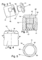
- die Sicherheitskupplung in einer sprengbildlichen Darstellung
- Figur 3
- die Sicherheitskupplung in Schnittdarstellung
- Figur 4
- die Sicherheitskupplung gemäß den
Figuren 2 und 3 in einer Ansicht, jedoch gegenüber derFigur 3 in einer um 90° gedrehten Stellung und - Figur 5
- eine der
Figur 4 entsprechende Draufsicht. - Die
Figur 1 zeigt, dass eine auf einer nicht dargestellten Achse eines Nutzfahrzeuges aufgesetzte Bremsscheibe 1 in einem Bremssattel 2 angeordnet ist. Beidseitig der Bremsscheibe 1 sind die Bremsbeläge 3, 4 montiert. Die Scheibenbremse ist ferner vorzugsweise mit einer Traverse 5 ausgestattet, in der zwei parallel und im Abstand zueinander angeordnete Nachstellspindeln 6, 7 montiert sind. Durch das Bezugszeichen 8 ist die gesamte Zuspannvorrichtung bezeichnet. Die beiden Nachstellspindeln 6, 7 sind über eine Synchronisationseinrichtung, im dargestellten Ausführungsbeispiel durch einen Kettentrieb 9 synchron miteinander gekoppelt. - Eine komplette Scheibenbremse ist beispielsweise in der
EP 0 566 008 A1 beschrieben. - Wie die
Figuren 2 bis 5 zeigen, besteht die Sicherheitskupplung 10 aus einer Hülse 11 mit einem Innengewinde und einem damit verschraubten Bolzen 12, der einen Gewindeschaft 13 aufweist. Der Bolzen 12 ist ferner noch mit einem außerhalb der Hülse 11 stehenden Sechskantkopf 14 versehen. - Der Bolzen 12 wird mit einem dem zulässigen Drehmoment entsprechenden Drehmoment mit der Hülse 11 verschraubt. Diese Verschraubung ist so ausgelegt, dass sich die Verbindung zwischen Bolzen 12 gegenüber Hülse 11 löst, wenn auf diesen Bolzen 12 ein gegenüber dem zulässigen Drehmoment größeres Drehmoment einwirkt. Zur formschlüssigen Verbindung ist die Hülse 11 an der dem Bolzen 12 abgewandten Seite mit einer inneren Verzahnung 17 in Form einer Sonderverzahnung versehen, wodurch die Sicherheit gegenüber einer Überlastung der Innenmechanik der Nachstellvorrichtung sichergestellt ist. Wie insbesondere die
Figur 3 zeigt, erstreckt sich das Innengewinde der Hülse 11 und die Verzahnung 17 in etwa über die halbe Länge der Hülse 11. - Damit nach einem Wechsel der Bremsbeläge der Scheibenbremse erkennbar ist, ob sich der Bolzen 12 gegenüber der Hülse 11 verdreht hat oder nicht, was bei einer Überlastung beim Vordrehen des Nachstellers eintreten könnte, sind im dargestellten Ausführungsbeispiel die Hülse 11 und der Bolzen 12 mit Markierungen versehen, die im dargestellten Ausführungsbeispiel durch jeweils einen Steg 18 und 19 von geringer Breite und Höhe gebildet sind. Im Gegensatz zu der dargestellten Ausführung könnten diese Markierungen auch nutartig sein. Im Normalbetriebszustand stehen die Markierungen bzw. die Stege 18, 19 fluchtend zueinander. Zur Vermeidung scharfer Kanten ist der Sechskantkopf 14 des Bolzens 12 an seinem freien Endbereich noch mit einer umlaufenden Fase 20 versehen.
- Die Erfindung ist nicht auf das dargestellte Ausführungsbeispiel beschränkt. Wesentlich ist, dass die Hülse und der Bolzen form- und/oder kraftschlüssig, vorzugsweise durch Gewinde miteinander gekoppelt sind, und dass beim Überschreiten des zulässigen Drehmomentes die beiden Bauteile relativ zueinander verdrehbar sind, wobei bevorzugt der Bolzen gegenüber der Hülse verdrehbar ist.
Claims (6)
- Scheibenbremse, die einen Bremssattel (2) umfasst, in dem eine Bremsscheibe (1) und zwei beidseitig der Bremsscheibe (1) angeordnete Bremsbeläge (3, 4) montiert sind, und die zur Kompensierung des Verschleißes der Bremsbeläge (3, 4) mit einer Nachstellvorrichtung ausgestattet ist, die mindestens eine Nachstellspindel (6, 7) aufweist, der eine beim Überschreiten eines bestimmten Drehmomentes ansprechende Sicherheitskupplung (10) zugeordnet ist, dadurch gekennzeichnet, dass die Sicherheitskupplung (10) aus einer Hülse (11) und einem darin derart form- und/oder kraftschlüssig eingesetzten Bolzen (12) besteht, dass beim Überschreiten des bestimmten Drehmomentes eine Relativbewegung zwischen der Hülse (11) und dem Bolzen (12) durchführbar ist.
- Scheibenbremse nach Anspruch 1, dadurch gekennzeichnet, dass die Hülse (11) mit einer Innengewindebohrung und der Bolzen (12) mit einem Schaft (13) mit einem Außengewinde versehen ist.
- Scheibenbremse nach Anspruch 1 oder 2, dadurch gekennzeichnet, dass die Hülse (11) und/oder der Bolzen (12) eine Markierung (18, 19) aufweisen.
- Scheibenbremse nach Anspruch 3, dadurch gekennzeichnet, dass jede Markierung aus einem Steg (18, 19) geringer Höhe und Breite oder aus einer nutartigen Vertiefung gebildet ist, und dass in der Normalbetriebsstellung die Markierungen (18, 19) fluchtend zueinander stehen, und dass nach dem Wechsel der Bremsbeläge (3, 4) eine Verdrehung des Bolzens (12) gegenüber der Hülse (11) erkennbar ist.
- Scheibenbremse nach einem oder mehreren der vorstehenden Ansprüche, dadurch gekennzeichnet, dass die Hülse (11) an der der Nachstellspindel (6, 7) zugewandten Seite mit einer Verzahnung versehen ist, und dass sich das Innengewinde und die Verzahnung (17) über die halbe Länge oder annähernd über die halbe Länge der Hülse (11) erstrecken.
- Scheibenbremse nach einem oder mehreren der vorstehenden Ansprüche, dadurch gekennzeichnet, dass die Hülse (11) der Nachstellvorrichtung zugewandt und der Bolzen (12) der Nachstellvorrichtung abgewandt liegt.
Applications Claiming Priority (1)
| Application Number | Priority Date | Filing Date | Title |
|---|---|---|---|
| DE200810005455 DE102008005455B4 (de) | 2008-01-22 | 2008-01-22 | Scheibenbremse mit Sicherheitskupplung für die Nachstelleinrichtung |
Publications (3)
| Publication Number | Publication Date |
|---|---|
| EP2083189A2 true EP2083189A2 (de) | 2009-07-29 |
| EP2083189A3 EP2083189A3 (de) | 2011-03-09 |
| EP2083189B1 EP2083189B1 (de) | 2016-08-03 |
Family
ID=40602445
Family Applications (1)
| Application Number | Title | Priority Date | Filing Date |
|---|---|---|---|
| EP09000764.2A Not-in-force EP2083189B1 (de) | 2008-01-22 | 2009-01-21 | Scheibenbremse mit Sicherheitskupplung für die Nachstelleinrichtung |
Country Status (2)
| Country | Link |
|---|---|
| EP (1) | EP2083189B1 (de) |
| DE (1) | DE102008005455B4 (de) |
Cited By (2)
| Publication number | Priority date | Publication date | Assignee | Title |
|---|---|---|---|---|
| CN102713333A (zh) * | 2009-12-28 | 2012-10-03 | 纳博特斯克株式会社 | 制动缸装置及盘形制动装置 |
| CN103154557A (zh) * | 2010-03-17 | 2013-06-12 | 瀚德刹车片产品公司 | 盘式制动器及其制造方法 |
Citations (2)
| Publication number | Priority date | Publication date | Assignee | Title |
|---|---|---|---|---|
| WO1996012114A1 (en) | 1994-10-17 | 1996-04-25 | Anglo Dutch International Finance N.V. | Fastening device |
| US5681135A (en) | 1995-01-19 | 1997-10-28 | Simonson; Peter Melott | Threaded fastener with multi-stage torque limiting applicator |
Family Cites Families (6)
| Publication number | Priority date | Publication date | Assignee | Title |
|---|---|---|---|---|
| GB810434A (en) * | 1957-07-09 | 1959-03-18 | Charmilles Sa Ateliers | Improvements in or relating to multi-part coupling nuts for automatic brake rod adjusting devices |
| DE4007483C2 (de) * | 1989-03-21 | 1997-02-20 | Moenninghoff Gmbh & Co Kg Masc | Überlastkupplung |
| DE4212405C2 (de) | 1992-04-13 | 2000-02-10 | Knorr Bremse Ag | Druckluftbetätigte Scheibenbremse |
| GB9516922D0 (en) * | 1995-08-18 | 1995-10-18 | Lucas Ind Plc | Brake adjuster mechanism |
| DE19923457C1 (de) * | 1999-05-21 | 2000-11-02 | Knorr Bremse Systeme | Verschleißnachstelleinrichtung für eine Bremse |
| GB0410659D0 (en) * | 2004-05-13 | 2004-06-16 | Meritor Heavy Vehicle Braking | Brake pad wear indicator |
-
2008
- 2008-01-22 DE DE200810005455 patent/DE102008005455B4/de not_active Expired - Fee Related
-
2009
- 2009-01-21 EP EP09000764.2A patent/EP2083189B1/de not_active Not-in-force
Patent Citations (2)
| Publication number | Priority date | Publication date | Assignee | Title |
|---|---|---|---|---|
| WO1996012114A1 (en) | 1994-10-17 | 1996-04-25 | Anglo Dutch International Finance N.V. | Fastening device |
| US5681135A (en) | 1995-01-19 | 1997-10-28 | Simonson; Peter Melott | Threaded fastener with multi-stage torque limiting applicator |
Cited By (4)
| Publication number | Priority date | Publication date | Assignee | Title |
|---|---|---|---|---|
| CN102713333A (zh) * | 2009-12-28 | 2012-10-03 | 纳博特斯克株式会社 | 制动缸装置及盘形制动装置 |
| CN102713333B (zh) * | 2009-12-28 | 2014-07-30 | 纳博特斯克株式会社 | 制动缸装置及盘形制动装置 |
| CN103154557A (zh) * | 2010-03-17 | 2013-06-12 | 瀚德刹车片产品公司 | 盘式制动器及其制造方法 |
| CN103154557B (zh) * | 2010-03-17 | 2016-03-16 | 瀚德刹车片产品公司 | 盘式制动器及其制造方法 |
Also Published As
| Publication number | Publication date |
|---|---|
| EP2083189B1 (de) | 2016-08-03 |
| DE102008005455A1 (de) | 2009-07-30 |
| DE102008005455B4 (de) | 2010-04-08 |
| EP2083189A3 (de) | 2011-03-09 |
Similar Documents
| Publication | Publication Date | Title |
|---|---|---|
| EP2315966B2 (de) | Scheibenbremse | |
| DE102008037774B3 (de) | Scheibenbremse, insbesondere für Nutzfahrzeuge | |
| EP0614025B1 (de) | Nachstellvorrichtung für eine Scheibenbremse | |
| EP0730107A2 (de) | Scheibenbremse | |
| WO2012163825A1 (de) | Welle mit einem lager | |
| EP2464894B1 (de) | Kugelgewindetrieb mit markierungen für anschlag und montageverfahren für einen solchen kugelgewindetrieb | |
| DE102015104183A1 (de) | Scheibenbremse für ein Nutzfahrzeug | |
| DE3045070A1 (de) | Einstellbare reibungskupplung | |
| WO2017081016A1 (de) | Scheibenbremse für ein nutzfahrzeug | |
| EP1565668B1 (de) | Schreibenbremse mit einer nachstelleinrichtung, insbesondere für ein nutzfahrzeug | |
| DE19632917B4 (de) | Bremsenjustiermechanismus | |
| DE102014204174B4 (de) | Drehmomentbegrenzende Rücklaufsperre | |
| EP3172456B1 (de) | Bremssystem | |
| DE2708538C3 (de) | Verbindung zwischen den Kettengliedern einer Gleiskette | |
| DE102008005454B4 (de) | Scheibenbremse mit Rutschkupplung für die Nachstelleinrichtung | |
| EP2083189B1 (de) | Scheibenbremse mit Sicherheitskupplung für die Nachstelleinrichtung | |
| EP2292945B1 (de) | Scheibenbremse mit Rutschkupplung für die Nachstelleinrichtung | |
| EP2055981B1 (de) | Fahrzeugbremse | |
| DE10248947B4 (de) | Scheibenbremse, insbesondere für ein Nutzfahrzeug | |
| DE102007019440B4 (de) | Scheibenbremse mit Lösespindel für die Nachstelleinrichtung | |
| DE102018113576B4 (de) | Nachstelleinrichtung einer Scheibenbremse | |
| EP0852301A1 (de) | Backenbremse | |
| DE19941210A1 (de) | Druckplattenbaugruppe | |
| DE202014011279U1 (de) | Spannmutter | |
| DE3044679A1 (de) | Einstellvorrichtung |
Legal Events
| Date | Code | Title | Description |
|---|---|---|---|
| PUAI | Public reference made under article 153(3) epc to a published international application that has entered the european phase |
Free format text: ORIGINAL CODE: 0009012 |
|
| 17P | Request for examination filed |
Effective date: 20090121 |
|
| AK | Designated contracting states |
Kind code of ref document: A2 Designated state(s): AT BE BG CH CY CZ DE DK EE ES FI FR GB GR HR HU IE IS IT LI LT LU LV MC MK MT NL NO PL PT RO SE SI SK TR |
|
| AX | Request for extension of the european patent |
Extension state: AL BA RS |
|
| PUAL | Search report despatched |
Free format text: ORIGINAL CODE: 0009013 |
|
| AK | Designated contracting states |
Kind code of ref document: A3 Designated state(s): AT BE BG CH CY CZ DE DK EE ES FI FR GB GR HR HU IE IS IT LI LT LU LV MC MK MT NL NO PL PT RO SE SI SK TR |
|
| AX | Request for extension of the european patent |
Extension state: AL BA RS |
|
| 17Q | First examination report despatched |
Effective date: 20110217 |
|
| AKX | Designation fees paid |
Designated state(s): AT BE BG CH CY CZ DE DK EE ES FI FR GB GR HR HU IE IS IT LI LT LU LV MC MK MT NL NO PL PT RO SE SI SK TR |
|
| GRAP | Despatch of communication of intention to grant a patent |
Free format text: ORIGINAL CODE: EPIDOSNIGR1 |
|
| INTG | Intention to grant announced |
Effective date: 20160229 |
|
| GRAS | Grant fee paid |
Free format text: ORIGINAL CODE: EPIDOSNIGR3 |
|
| GRAA | (expected) grant |
Free format text: ORIGINAL CODE: 0009210 |
|
| AK | Designated contracting states |
Kind code of ref document: B1 Designated state(s): AT BE BG CH CY CZ DE DK EE ES FI FR GB GR HR HU IE IS IT LI LT LU LV MC MK MT NL NO PL PT RO SE SI SK TR |
|
| REG | Reference to a national code |
Ref country code: GB Ref legal event code: FG4D Free format text: NOT ENGLISH |
|
| REG | Reference to a national code |
Ref country code: CH Ref legal event code: EP Ref country code: AT Ref legal event code: REF Ref document number: 817541 Country of ref document: AT Kind code of ref document: T Effective date: 20160815 |
|
| REG | Reference to a national code |
Ref country code: IE Ref legal event code: FG4D Free format text: LANGUAGE OF EP DOCUMENT: GERMAN |
|
| REG | Reference to a national code |
Ref country code: DE Ref legal event code: R096 Ref document number: 502009012892 Country of ref document: DE |
|
| REG | Reference to a national code |
Ref country code: SE Ref legal event code: TRGR |
|
| REG | Reference to a national code |
Ref country code: NL Ref legal event code: MP Effective date: 20160803 |
|
| REG | Reference to a national code |
Ref country code: LT Ref legal event code: MG4D |
|
| PG25 | Lapsed in a contracting state [announced via postgrant information from national office to epo] |
Ref country code: LT Free format text: LAPSE BECAUSE OF FAILURE TO SUBMIT A TRANSLATION OF THE DESCRIPTION OR TO PAY THE FEE WITHIN THE PRESCRIBED TIME-LIMIT Effective date: 20160803 Ref country code: IT Free format text: LAPSE BECAUSE OF FAILURE TO SUBMIT A TRANSLATION OF THE DESCRIPTION OR TO PAY THE FEE WITHIN THE PRESCRIBED TIME-LIMIT Effective date: 20160803 Ref country code: FI Free format text: LAPSE BECAUSE OF FAILURE TO SUBMIT A TRANSLATION OF THE DESCRIPTION OR TO PAY THE FEE WITHIN THE PRESCRIBED TIME-LIMIT Effective date: 20160803 Ref country code: NL Free format text: LAPSE BECAUSE OF FAILURE TO SUBMIT A TRANSLATION OF THE DESCRIPTION OR TO PAY THE FEE WITHIN THE PRESCRIBED TIME-LIMIT Effective date: 20160803 Ref country code: IS Free format text: LAPSE BECAUSE OF FAILURE TO SUBMIT A TRANSLATION OF THE DESCRIPTION OR TO PAY THE FEE WITHIN THE PRESCRIBED TIME-LIMIT Effective date: 20161203 Ref country code: NO Free format text: LAPSE BECAUSE OF FAILURE TO SUBMIT A TRANSLATION OF THE DESCRIPTION OR TO PAY THE FEE WITHIN THE PRESCRIBED TIME-LIMIT Effective date: 20161103 Ref country code: HR Free format text: LAPSE BECAUSE OF FAILURE TO SUBMIT A TRANSLATION OF THE DESCRIPTION OR TO PAY THE FEE WITHIN THE PRESCRIBED TIME-LIMIT Effective date: 20160803 |
|
| PG25 | Lapsed in a contracting state [announced via postgrant information from national office to epo] |
Ref country code: LV Free format text: LAPSE BECAUSE OF FAILURE TO SUBMIT A TRANSLATION OF THE DESCRIPTION OR TO PAY THE FEE WITHIN THE PRESCRIBED TIME-LIMIT Effective date: 20160803 Ref country code: PT Free format text: LAPSE BECAUSE OF FAILURE TO SUBMIT A TRANSLATION OF THE DESCRIPTION OR TO PAY THE FEE WITHIN THE PRESCRIBED TIME-LIMIT Effective date: 20161205 Ref country code: PL Free format text: LAPSE BECAUSE OF FAILURE TO SUBMIT A TRANSLATION OF THE DESCRIPTION OR TO PAY THE FEE WITHIN THE PRESCRIBED TIME-LIMIT Effective date: 20160803 Ref country code: ES Free format text: LAPSE BECAUSE OF FAILURE TO SUBMIT A TRANSLATION OF THE DESCRIPTION OR TO PAY THE FEE WITHIN THE PRESCRIBED TIME-LIMIT Effective date: 20160803 Ref country code: GR Free format text: LAPSE BECAUSE OF FAILURE TO SUBMIT A TRANSLATION OF THE DESCRIPTION OR TO PAY THE FEE WITHIN THE PRESCRIBED TIME-LIMIT Effective date: 20161104 |
|
| PG25 | Lapsed in a contracting state [announced via postgrant information from national office to epo] |
Ref country code: EE Free format text: LAPSE BECAUSE OF FAILURE TO SUBMIT A TRANSLATION OF THE DESCRIPTION OR TO PAY THE FEE WITHIN THE PRESCRIBED TIME-LIMIT Effective date: 20160803 Ref country code: RO Free format text: LAPSE BECAUSE OF FAILURE TO SUBMIT A TRANSLATION OF THE DESCRIPTION OR TO PAY THE FEE WITHIN THE PRESCRIBED TIME-LIMIT Effective date: 20160803 |
|
| REG | Reference to a national code |
Ref country code: DE Ref legal event code: R097 Ref document number: 502009012892 Country of ref document: DE |
|
| PG25 | Lapsed in a contracting state [announced via postgrant information from national office to epo] |
Ref country code: SK Free format text: LAPSE BECAUSE OF FAILURE TO SUBMIT A TRANSLATION OF THE DESCRIPTION OR TO PAY THE FEE WITHIN THE PRESCRIBED TIME-LIMIT Effective date: 20160803 Ref country code: BG Free format text: LAPSE BECAUSE OF FAILURE TO SUBMIT A TRANSLATION OF THE DESCRIPTION OR TO PAY THE FEE WITHIN THE PRESCRIBED TIME-LIMIT Effective date: 20161103 Ref country code: BE Free format text: LAPSE BECAUSE OF NON-PAYMENT OF DUE FEES Effective date: 20170131 Ref country code: DK Free format text: LAPSE BECAUSE OF FAILURE TO SUBMIT A TRANSLATION OF THE DESCRIPTION OR TO PAY THE FEE WITHIN THE PRESCRIBED TIME-LIMIT Effective date: 20160803 Ref country code: CZ Free format text: LAPSE BECAUSE OF FAILURE TO SUBMIT A TRANSLATION OF THE DESCRIPTION OR TO PAY THE FEE WITHIN THE PRESCRIBED TIME-LIMIT Effective date: 20160803 |
|
| PLBE | No opposition filed within time limit |
Free format text: ORIGINAL CODE: 0009261 |
|
| STAA | Information on the status of an ep patent application or granted ep patent |
Free format text: STATUS: NO OPPOSITION FILED WITHIN TIME LIMIT |
|
| 26N | No opposition filed |
Effective date: 20170504 |
|
| PG25 | Lapsed in a contracting state [announced via postgrant information from national office to epo] |
Ref country code: SI Free format text: LAPSE BECAUSE OF FAILURE TO SUBMIT A TRANSLATION OF THE DESCRIPTION OR TO PAY THE FEE WITHIN THE PRESCRIBED TIME-LIMIT Effective date: 20160803 |
|
| REG | Reference to a national code |
Ref country code: CH Ref legal event code: PL |
|
| GBPC | Gb: european patent ceased through non-payment of renewal fee |
Effective date: 20170121 |
|
| PG25 | Lapsed in a contracting state [announced via postgrant information from national office to epo] |
Ref country code: MC Free format text: LAPSE BECAUSE OF FAILURE TO SUBMIT A TRANSLATION OF THE DESCRIPTION OR TO PAY THE FEE WITHIN THE PRESCRIBED TIME-LIMIT Effective date: 20160803 |
|
| REG | Reference to a national code |
Ref country code: FR Ref legal event code: ST Effective date: 20170929 |
|
| PG25 | Lapsed in a contracting state [announced via postgrant information from national office to epo] |
Ref country code: FR Free format text: LAPSE BECAUSE OF NON-PAYMENT OF DUE FEES Effective date: 20170131 Ref country code: CH Free format text: LAPSE BECAUSE OF NON-PAYMENT OF DUE FEES Effective date: 20170131 Ref country code: LI Free format text: LAPSE BECAUSE OF NON-PAYMENT OF DUE FEES Effective date: 20170131 |
|
| REG | Reference to a national code |
Ref country code: IE Ref legal event code: MM4A |
|
| PG25 | Lapsed in a contracting state [announced via postgrant information from national office to epo] |
Ref country code: GB Free format text: LAPSE BECAUSE OF NON-PAYMENT OF DUE FEES Effective date: 20170121 Ref country code: LU Free format text: LAPSE BECAUSE OF NON-PAYMENT OF DUE FEES Effective date: 20170121 |
|
| REG | Reference to a national code |
Ref country code: BE Ref legal event code: MM Effective date: 20170131 |
|
| PG25 | Lapsed in a contracting state [announced via postgrant information from national office to epo] |
Ref country code: IE Free format text: LAPSE BECAUSE OF NON-PAYMENT OF DUE FEES Effective date: 20170121 |
|
| REG | Reference to a national code |
Ref country code: AT Ref legal event code: MM01 Ref document number: 817541 Country of ref document: AT Kind code of ref document: T Effective date: 20170121 |
|
| PG25 | Lapsed in a contracting state [announced via postgrant information from national office to epo] |
Ref country code: AT Free format text: LAPSE BECAUSE OF NON-PAYMENT OF DUE FEES Effective date: 20170121 |
|
| PG25 | Lapsed in a contracting state [announced via postgrant information from national office to epo] |
Ref country code: MT Free format text: LAPSE BECAUSE OF FAILURE TO SUBMIT A TRANSLATION OF THE DESCRIPTION OR TO PAY THE FEE WITHIN THE PRESCRIBED TIME-LIMIT Effective date: 20160803 |
|
| PG25 | Lapsed in a contracting state [announced via postgrant information from national office to epo] |
Ref country code: HU Free format text: LAPSE BECAUSE OF FAILURE TO SUBMIT A TRANSLATION OF THE DESCRIPTION OR TO PAY THE FEE WITHIN THE PRESCRIBED TIME-LIMIT; INVALID AB INITIO Effective date: 20090121 |
|
| PG25 | Lapsed in a contracting state [announced via postgrant information from national office to epo] |
Ref country code: CY Free format text: LAPSE BECAUSE OF NON-PAYMENT OF DUE FEES Effective date: 20160803 |
|
| PG25 | Lapsed in a contracting state [announced via postgrant information from national office to epo] |
Ref country code: MK Free format text: LAPSE BECAUSE OF FAILURE TO SUBMIT A TRANSLATION OF THE DESCRIPTION OR TO PAY THE FEE WITHIN THE PRESCRIBED TIME-LIMIT Effective date: 20160803 |
|
| PG25 | Lapsed in a contracting state [announced via postgrant information from national office to epo] |
Ref country code: TR Free format text: LAPSE BECAUSE OF FAILURE TO SUBMIT A TRANSLATION OF THE DESCRIPTION OR TO PAY THE FEE WITHIN THE PRESCRIBED TIME-LIMIT Effective date: 20160803 |
|
| PGFP | Annual fee paid to national office [announced via postgrant information from national office to epo] |
Ref country code: DE Payment date: 20210429 Year of fee payment: 13 |
|
| REG | Reference to a national code |
Ref country code: DE Ref legal event code: R119 Ref document number: 502009012892 Country of ref document: DE |
|
| PG25 | Lapsed in a contracting state [announced via postgrant information from national office to epo] |
Ref country code: DE Free format text: LAPSE BECAUSE OF NON-PAYMENT OF DUE FEES Effective date: 20220802 |
|
| PGFP | Annual fee paid to national office [announced via postgrant information from national office to epo] |
Ref country code: SE Payment date: 20230123 Year of fee payment: 15 |
|
| P01 | Opt-out of the competence of the unified patent court (upc) registered |
Effective date: 20230607 |
|
| REG | Reference to a national code |
Ref country code: SE Ref legal event code: EUG |
|
| PG25 | Lapsed in a contracting state [announced via postgrant information from national office to epo] |
Ref country code: SE Free format text: LAPSE BECAUSE OF NON-PAYMENT OF DUE FEES Effective date: 20240122 |