EP2082719A1 - Multichamber container - Google Patents
Multichamber container Download PDFInfo
- Publication number
- EP2082719A1 EP2082719A1 EP07831121A EP07831121A EP2082719A1 EP 2082719 A1 EP2082719 A1 EP 2082719A1 EP 07831121 A EP07831121 A EP 07831121A EP 07831121 A EP07831121 A EP 07831121A EP 2082719 A1 EP2082719 A1 EP 2082719A1
- Authority
- EP
- European Patent Office
- Prior art keywords
- weld
- medical
- medical bag
- outlet port
- partitions
- Prior art date
- Legal status (The legal status is an assumption and is not a legal conclusion. Google has not performed a legal analysis and makes no representation as to the accuracy of the status listed.)
- Granted
Links
- 238000005192 partition Methods 0.000 claims abstract description 54
- 239000003814 drug Substances 0.000 claims abstract description 20
- 229940079593 drug Drugs 0.000 claims abstract description 15
- 239000007788 liquid Substances 0.000 claims description 43
- 238000000926 separation method Methods 0.000 claims description 20
- 238000003466 welding Methods 0.000 claims description 19
- 238000003825 pressing Methods 0.000 claims description 18
- 230000005540 biological transmission Effects 0.000 claims description 17
- 230000002093 peripheral effect Effects 0.000 claims description 9
- 238000004891 communication Methods 0.000 claims description 7
- 239000012530 fluid Substances 0.000 claims description 6
- 238000000034 method Methods 0.000 claims description 2
- 238000007599 discharging Methods 0.000 claims 4
- 239000000203 mixture Substances 0.000 abstract description 2
- 238000001802 infusion Methods 0.000 description 7
- 239000004698 Polyethylene Substances 0.000 description 4
- -1 polyethylene Polymers 0.000 description 4
- 229920000573 polyethylene Polymers 0.000 description 4
- 229920003002 synthetic resin Polymers 0.000 description 4
- 239000000057 synthetic resin Substances 0.000 description 4
- 238000003860 storage Methods 0.000 description 3
- 230000000694 effects Effects 0.000 description 2
- 239000008213 purified water Substances 0.000 description 2
- 230000001954 sterilising effect Effects 0.000 description 2
- 238000012360 testing method Methods 0.000 description 2
- XLYOFNOQVPJJNP-UHFFFAOYSA-N water Chemical compound O XLYOFNOQVPJJNP-UHFFFAOYSA-N 0.000 description 2
- 230000009471 action Effects 0.000 description 1
- 230000002146 bilateral effect Effects 0.000 description 1
- 230000008859 change Effects 0.000 description 1
- 238000010276 construction Methods 0.000 description 1
- 230000000977 initiatory effect Effects 0.000 description 1
- 238000004519 manufacturing process Methods 0.000 description 1
- 239000000463 material Substances 0.000 description 1
- 230000004048 modification Effects 0.000 description 1
- 238000012986 modification Methods 0.000 description 1
- 239000004033 plastic Substances 0.000 description 1
- 229920003023 plastic Polymers 0.000 description 1
- 230000008569 process Effects 0.000 description 1
- 238000004659 sterilization and disinfection Methods 0.000 description 1
Images


Classifications
-
- B—PERFORMING OPERATIONS; TRANSPORTING
- B65—CONVEYING; PACKING; STORING; HANDLING THIN OR FILAMENTARY MATERIAL
- B65D—CONTAINERS FOR STORAGE OR TRANSPORT OF ARTICLES OR MATERIALS, e.g. BAGS, BARRELS, BOTTLES, BOXES, CANS, CARTONS, CRATES, DRUMS, JARS, TANKS, HOPPERS, FORWARDING CONTAINERS; ACCESSORIES, CLOSURES, OR FITTINGS THEREFOR; PACKAGING ELEMENTS; PACKAGES
- B65D81/00—Containers, packaging elements, or packages, for contents presenting particular transport or storage problems, or adapted to be used for non-packaging purposes after removal of contents
- B65D81/32—Containers, packaging elements, or packages, for contents presenting particular transport or storage problems, or adapted to be used for non-packaging purposes after removal of contents for packaging two or more different materials which must be maintained separate prior to use in admixture
-
- B—PERFORMING OPERATIONS; TRANSPORTING
- B65—CONVEYING; PACKING; STORING; HANDLING THIN OR FILAMENTARY MATERIAL
- B65D—CONTAINERS FOR STORAGE OR TRANSPORT OF ARTICLES OR MATERIALS, e.g. BAGS, BARRELS, BOTTLES, BOXES, CANS, CARTONS, CRATES, DRUMS, JARS, TANKS, HOPPERS, FORWARDING CONTAINERS; ACCESSORIES, CLOSURES, OR FITTINGS THEREFOR; PACKAGING ELEMENTS; PACKAGES
- B65D81/00—Containers, packaging elements, or packages, for contents presenting particular transport or storage problems, or adapted to be used for non-packaging purposes after removal of contents
- B65D81/32—Containers, packaging elements, or packages, for contents presenting particular transport or storage problems, or adapted to be used for non-packaging purposes after removal of contents for packaging two or more different materials which must be maintained separate prior to use in admixture
- B65D81/3261—Flexible containers having several compartments
- B65D81/3266—Flexible containers having several compartments separated by a common rupturable seal, a clip or other removable fastening device
-
- A—HUMAN NECESSITIES
- A61—MEDICAL OR VETERINARY SCIENCE; HYGIENE
- A61J—CONTAINERS SPECIALLY ADAPTED FOR MEDICAL OR PHARMACEUTICAL PURPOSES; DEVICES OR METHODS SPECIALLY ADAPTED FOR BRINGING PHARMACEUTICAL PRODUCTS INTO PARTICULAR PHYSICAL OR ADMINISTERING FORMS; DEVICES FOR ADMINISTERING FOOD OR MEDICINES ORALLY; BABY COMFORTERS; DEVICES FOR RECEIVING SPITTLE
- A61J1/00—Containers specially adapted for medical or pharmaceutical purposes
- A61J1/05—Containers specially adapted for medical or pharmaceutical purposes for collecting, storing or administering blood, plasma or medical fluids ; Infusion or perfusion containers
-
- A—HUMAN NECESSITIES
- A61—MEDICAL OR VETERINARY SCIENCE; HYGIENE
- A61J—CONTAINERS SPECIALLY ADAPTED FOR MEDICAL OR PHARMACEUTICAL PURPOSES; DEVICES OR METHODS SPECIALLY ADAPTED FOR BRINGING PHARMACEUTICAL PRODUCTS INTO PARTICULAR PHYSICAL OR ADMINISTERING FORMS; DEVICES FOR ADMINISTERING FOOD OR MEDICINES ORALLY; BABY COMFORTERS; DEVICES FOR RECEIVING SPITTLE
- A61J1/00—Containers specially adapted for medical or pharmaceutical purposes
- A61J1/14—Details; Accessories therefor
- A61J1/20—Arrangements for transferring or mixing fluids, e.g. from vial to syringe
- A61J1/2093—Containers having several compartments for products to be mixed
-
- A—HUMAN NECESSITIES
- A61—MEDICAL OR VETERINARY SCIENCE; HYGIENE
- A61J—CONTAINERS SPECIALLY ADAPTED FOR MEDICAL OR PHARMACEUTICAL PURPOSES; DEVICES OR METHODS SPECIALLY ADAPTED FOR BRINGING PHARMACEUTICAL PRODUCTS INTO PARTICULAR PHYSICAL OR ADMINISTERING FORMS; DEVICES FOR ADMINISTERING FOOD OR MEDICINES ORALLY; BABY COMFORTERS; DEVICES FOR RECEIVING SPITTLE
- A61J1/00—Containers specially adapted for medical or pharmaceutical purposes
- A61J1/05—Containers specially adapted for medical or pharmaceutical purposes for collecting, storing or administering blood, plasma or medical fluids ; Infusion or perfusion containers
- A61J1/10—Bag-type containers
-
- A—HUMAN NECESSITIES
- A61—MEDICAL OR VETERINARY SCIENCE; HYGIENE
- A61J—CONTAINERS SPECIALLY ADAPTED FOR MEDICAL OR PHARMACEUTICAL PURPOSES; DEVICES OR METHODS SPECIALLY ADAPTED FOR BRINGING PHARMACEUTICAL PRODUCTS INTO PARTICULAR PHYSICAL OR ADMINISTERING FORMS; DEVICES FOR ADMINISTERING FOOD OR MEDICINES ORALLY; BABY COMFORTERS; DEVICES FOR RECEIVING SPITTLE
- A61J1/00—Containers specially adapted for medical or pharmaceutical purposes
- A61J1/14—Details; Accessories therefor
- A61J1/20—Arrangements for transferring or mixing fluids, e.g. from vial to syringe
- A61J1/2003—Accessories used in combination with means for transfer or mixing of fluids, e.g. for activating fluid flow, separating fluids, filtering fluid or venting
- A61J1/202—Separating means
- A61J1/2024—Separating means having peelable seals
Definitions
- the present invention relates to a multi-chamber container, which is formed as a medical bag having a separable welded part, which divides the space in the bag into compartments for storing separately medical liquids, which are, after subjected to a mixing operation, discharged from an outlet port.
- a multi-chamber container for an infusion has here-to-fore known, which has a medical bag made of soft film having opposite layers, which are welded with each at relatively low temperature, so that a weak seal (separable welded portion) is created for dividing the bag into compartments for separately storing different medical liquids.
- An outlet port as a molded product is connected to an outer peripheral portion of the medical bag.
- the outlet port is formed as a tubular shape having an inner cavity, which cavity has one end opened to one of the compartments and a second end provided with a rubber plug.
- the medical bag Prior to the commencement of an infusion operation for giving medicines to a patient, the medical bag is outwardly pressed, which causes the weak seal to be separated and broken, so that inner cavities in the bag are communicated as a single chamber, so that the two kinds of medical liquids are mixed with each other.
- a piercing of the rubber plug by a needle of an infusion set allows the medicines from the medical bag to be given.
- an operation for separating the weak seal for mixing medial liquids is essential prior to the administration of the medicine.
- the weak seal is maintained under non-opened condition, the piercing of the rubber plug results in an erroneous operation that the medical liquid located only at one of chambers adjacent the outlet port is given.
- a medical bag having modified configuration of a weak seal for separation of the space inside the bag into two compartments, which weak seal has a bifurcated or A shaped portion located in front of the outlet port.
- This portion of the weak seal creates a third chamber, which communicates with the outlet port, on one hand and, on the other hand, is disconnected from the medical liquid storage compartments.
- the weak seal for separating medical liquid storage compartments includes a V-shaped portion, by which a separation of the weak seal is promoted. See patent document No.1.
- the weak seal extends along the almost entire length of the medial bag between the compartments storing the respective medical liquids and connects with the bifurcated portion for creating the third chamber.
- This structure of the weak seal aims to obtain a positive two staged opening operation that, prior to the separation of the bifurcated portion, the portion separating the compartments is done, firstly, for mixing the medical liquids in the compartments and, secondly, the mixed medical liquid is discharged.
- the portion of the weak seal extending between the medical liquid compartments is longer than the bifurcated portion. Therefore, the weak seal portion between the compartments likely generates a larger separation force upon the opening of the medical bag and, therefore, can be expected to be separated earlier than the bifurcated portion while taking a consideration that the V-shaped portion for initiating the separation operation is provided.
- the initial separation of the weak seal is not necessarily initiated at the portion between the partitions.
- the weak seal is separated by an expanded deformation of the medical bag as generated when the medical bag is subjected to a pressing force from its outside.
- the expanded deformation is equally transmitted not only to the portion between the partitions but also to the bifurcated portion. Therefore, it is most likely that the opening is, at first, commenced at the portion separating the partitions due to the increased length of the latter portion. It may, however, be frequently occurred that the bifurcated portion is, at first, separated, depending on the location where the pressure is applied.
- the present invention aims to provide a new structure of a medical bag of a multi-liquid mixing type, wherein an administration is prohibited under a non-opened condition, capable of reducing the production cost as well as of increasing the efficiency during use by a user, while positively reducing a chance of occurrence of erroneous operation.
- a separable weld is for welding opposed surfaces of flexible films constructing the medical bag, so that a plurality of partitions for storing, respectively, medical fluids are formed inside the medical bag.
- the separable weld may, for example, have a construction that it includes a first portion between the partitions from the periphery of the medical bag to a location adjacent to and faced with the outlet port and a second portion extending from both sides of the first portion to peripheral edges of the medical bag, in order to create an intermediate chamber between the faced surface of the flexible films, which intermediate chamber is opened to the outlet port while being separated from the partitions.
- the second portion may, for example, have a shape bifurcated from the second portion and extends to the peripheral parts of the medical bag, astride the outlet port.
- the second portion is at least partially separable for obtaining a communication of mixed medicines to the outlet port as obtained by a separation of said first portion.
- a provision is made as to a restrictor of transmission of a inflated deformation of the medical bag to the separable weld, as generated by an initial pressing of medical liquid stored in the partition of the bag in a manner that the deformation is substantially instantly transmitted to the first portion and that a transmission of the deformation to the second portion is restricted or prohibited.
- a second weld for non-separable welding of the opposed surfaces of the films of the medical bag is, for example, provided.
- the second weld restricts the transmission of an inflated deformation of the medical bag to the second portion of the first weld, as generated when the medical liquid stored in the partition is pressed.
- the second welds which are constructed by a non-separable welding of the opposed surfaces of the medical bag, are arranged on both sides of the outlet port so as to extend laterally, preferably, transversely from the first part of the first weld to the periphery of the medical bag.
- the second weld controls or restricts the transmission of the direction of inflated deformation in such a manner that the separation of the first weld occurs first and mainly at its first portion lather than its second portion.
- the provision of the restrictor or the second weld makes it possible that a restriction occurs in a transmission of an inflated deformation of the medical bag as generated by the outward pressing of the medical bag for opening the same, i.e. , the inflated deformation is mainly directed to the first portion and is almost not transmitted to the second portion. Therefore, a separation of the first portion initially occurs, thereby positively mixing the medical liquids. Then, a further separating operation of the second portion is executed, which allows the mixed liquid to be flown into the outlet port.
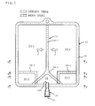
- a multi-chamber container has a flattened medical bag 10 for storing medical liquids and an outlet port 12.
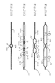
- the medical bag 10 is made of a material as a synthetic resin film (flexible film of the claimed invention), such as polyethylene film, of a multiple layer structure of a thickness of a value of, for example, 200 microns. From the synthetic resin film for constructing the medical bag 10, a pair of upper and lower cut pieces or upper and lower layers 10A and 10B are provided, which are superimposed so as to sandwich the tubular outlet port 12 ( Figure 2(D) .
- a high temperature welding at a temperature of a value such as 130°C in case of polyethylene film is done along the entire periphery.
- a strong seal 14 (non-separable weld) is obtained along the entire periphery including the portion of the tubular outlet port 12, so that a bag shape is created.
- the welding for obtaining the strong seal 14 is executed at a temperature of a value about 130°C in case of polyethylene film as above. This temperature value is high enough for preventing any separation under a pressure as normally generated in the medical bag when the bag is pressed in order to open the medical bag 10.
- the tubular outlet port 12 is made as a plastic molded produce having a wall thickness (rigidity), which is large enough to keep its tubular shape.
- the tubular outlet port 12 is, at its bottom end in Figure 1 , projected out of the medical bag 10.
- a rubber plug (plug member) 20 is arranged, which plug is to be pierced by a needle of an infusion set (not shown) .
- the medical bag 10 is made from a tubular film in place of the welded structure of the upper and bottom pierces cut from a film.
- a separable welding of two pierces of a synthetic resin film 10A and 10B at the top and bottom is done in order to form a weak seal 24 (a separable weld or first weld of the claimed invention), which weak seal extends vertically at the middle of the width of the medical bag 10, in a manner that the space inside the medical bag is separated to a left-handed and a right-handed partitions 26-1 and 26-2 for storing medical liquids, respectively ( Figure 2(A) ).
- the degree of the welding between two pierces of a synthetic resin film at the top and bottom of the medical bag 10 is such that a capability of a pressing separation is obtained.
- the weak seal 24 is constructed by a first portion 24-1, which extends downwardly from the upper periphery of the medical bag between the left-handed and the right-handed partitions 26-1 and 26-2 toward the location faced with and adjacent to the open end 12A of the outlet port 12 and by a second portion 24-2 ( Fig. 2(B) and 2(C) ), which extends from the first portion 24-1 bi-laterally in a bifurcates shape toward the bottom periphery of the medical bag 10, so that a third chamber 28 is created, which third chamber is separated from the partitions 26-1 and 26-2 by the second portion 24-2, while being in communication with the outlet port 12.
- additional strong seals 30-1 and 30-2 are provided on both sides of the outlet port 12, which strong seal is a restrictor or a second weld according to the present invention, which restricts the transmission of a force generated by an inflated deformation of the medical bag when the medical bag is opened in such a manner that the force is mainly transmitted to the first portion 24-1, while no transmission of the same to the second portion 24-1 is substantially occurs.
- the additional seals 30-1 and 30-2 are formed by welding the opposed faces of films constructing the medical bag at the temperature of substantially the same degree as that for obtaining the strong seal 14 at the outer periphery of the medical bag for preventing the opposed films from being separated by the outside force under the inflation of the medical bag as obtained when the latter is opened.
- the additional seals 30-1 and 30-2 extend, firstly, from the left-handed and right-handed peripheral portions (strong seal 14) of the medical bag, to locations adjacent to and faced with the weak seal 24, i.e., positions of connection between the first portion 24-1 and the second portion 24-2, in a direction transverse to the first portion 24-1, then, change direction at right angle, and, finally, extend downwardly to the bottom periphery (strong seal 14) of the medical bag after crossing the second portion 24-2 of the weak seal 24. Since the additional seals 30-1 and 30-2 are separated at the location where the outlet port 12 is provided, so that any blockage of flow of the medical fluid toward the outlet port 12 does not occur.
- the additional seals 30-1 and 30-2 divide the partitions 26-1 and 26-2, at the bottom parts, and create small chambers 32-1 and 32-2 ( Figs. 2C ).
- the small chambers 32-1 and 32-2 are located at the bottom sides of the medical bag 10 and, therefore, any obstruction of a flow of the medical liquid to the outlet port 12 does not occur after the communication of the partitions 261-and 26-1 as obtained by the opening of the weak seal 24. In short, the medical liquids in the medical bag are introduced into the outlet port 12 without being remained in the bag.
- an upper and lower film cut pierces 10A and 10B are faced with each other and welded at a high temperature for creating strong seals 14 and 30-1 and 30-2. Then, a low temperature is done for creating a weak seal (24-1 and 24-2).
- the strong seal 14 at the outer periphery of the medical bag has openings, i.e., non-welded portions, which open to the partitions 26-1 and 26-1, respectively.
- medical fluids are filled by way of the respective openings, which are, then, welded and sealed.
- the intermediate chamber 28 is also formed with an opening, through which purified water is filled and which opening is, then, welded and sealed. Since the purified water in the intermediate chamber 28 is also opened to the outlet port 12, a subsequent sterilizing process is executed under a wet heat condition, resulting in high sterilization efficiency.
- the medical bag In order to execute an opening operation, the medical bag is placed, for example, on a desk and is outwardly pressed by palm at one of the partitions 26-1 and 26-2 storing the medical liquids or both as shown by arrows g ( Fig. 2(A) , so that the medical bag as pressed and storing the medical liquid is inflated and the resultant inflation is transmitted to the weak seal 24. As a result, a separation of the welded film layers 10A and 10B constructing the weak seal 24 is generated.
- the additional strong seals 30-1 and 30-2 extend transverse to the first portion 24-1 of the weak seal 24 and are located on both sides of the second portion 24-2 of the weak seal 24.
- a inflated deformation of the medical bag as obtained when the partition 26-1 or 26-2 is pressed, is mainly transmitted to the first portion 24-1 in a shown left or right direction as illustrated by arrows f due to the guiding action as obtained by the additional strong seals 30-1 and 30-2. Therefore, a separation force is large at the first portion 24-1 and is small at the second portion 24-2. Therefore, a separation at the first portion 24-1 as shown by the phantom lines L 1 occurs initially, which allows the medical liquids in the partitions 26-1 and 26-2 to be mixed with each other. After the mixing, the second stage pressing is done in a manner that the second portion 24-2 of the weak seal 24 is separated and opened, which allows the mixed liquid to be introduced into the outlet port 12.
- the additional strong seal 30-1 or 30-2 has a vertical location, whereat, in the weak seal 24, the first portion 24-1 is connected to the second portion 24-2.
- the present invention is not limited to this arrangement and, therefore, a more lowered location than shown in the drawing is possible, so long as an operation for restricting the transmission of the inflated deformation to the second portion 24-2, as obtained when the pressing of the medical liquid stored in the partition 26-1 or 26-2, is done.
- the strong seal 14 at the bottom outer periphery of the medical bag may extend as similar as the additional strong seals 30-1 or 30-2 in Figure 1 does. In this case, the strong seal 14 itself functions as the restrictor of the transmission of the inflated deformation to the second portion 24-2 upon the pressing of the medical liquid.
- Figure 3 illustrates a prior art medical bag with no provision of any additional strong seal in the present invention.
- the inventors of the present invention executed opening test by several testers.
- the instruction to the testers was that the pressing of the medical bag should be done at the central part P of the left-handed partition 26-1 adj acent the second portion 24-1 of the weak seal 14.
- an inevitable variation is occurred as to the location where the opening is occurred, as typically illustrated by the three position a , b or c .
- the initial occurrence of the opening at the position a or b makes the liquids between the partitions 26-1 and 26-2 to be mixed.
- the initial opening at the position c occurs at a significant rate and, in this case, there will be a chance that an infusion is done at a non-mixed state or insufficient mixed state.
- the provision of the additional strong seals 30-1 and 30-2 according to the present invention makes it sure that the separation occurs initially at the first portion 24-1 of the weak seal, resulting in a positive mixture of the medial liquids prior to the commencement of infusion operation.
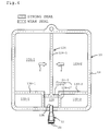
- Figure 4 illustrates second embodiment of the present invention, where the first weld 124 has a first portion 124-1 and a second portion 124-2.
- the first portion 124-1 extends between the left-handed and right-handed partitions from the upper periphery (strong seal 14) of the medical bag 10 to a location adjacent to and faced with the outlet port 12.
- the first portion 124-1 (a weak seal) is separable along its entire length.
- the second portion 124 of the first weld has separable parts 124-2' (weak seals) extending left-handed and right-handed directions from the first portion 124-1 and non-separable parts 124-2" (strong seals) extending, at both sides of the outlet port 12, from the separable parts 124-2' to the bottom periphery (strong seal 14) of the medical bag 10.
- the additional seals 130-1 and 130-2 are for mainly directing the inflated deformation of the medial bag to the first portion 124-1 of the first weld as shown by the arrows f , as generated when opening the medical bag and extend, at first, upwardly, as the extensions of the non-separable parts 124-2" and, then, horizontally in a manner that small chambers 132-1 and 132-2 are created, which are independent not only from the partitions 126-1 and 126-2 but also from the intermediate chamber 128.
- a high temperature welding is done for obtaining the seals 14, 124-2", 130-1 and 130-2, to obtain non-separable seals (strong seals). Therefore, in this embodiment, a welding head for a strong seal is advantageously of a shape, which forms simultaneously the non-separate portion 124-2" of the first weld and the additional strong seals 130-1 and 130-2 as the second weld.
- a low temperature welding is executed for obtaining the separable welded portions 124-1 and 124-2'.
- the deformation (inflation) as generated by the pressing of the partition 126-1 or 126-2 is, as shown by arrows f , mainly transmitted to the weak seal 124-1 horizontally separating the partitions 126-1 and 126-2. Therefore, the separation of the weak seal 124-1 occurs at first, resulting in the mixing of the medicines between the partitions 126-1 and 126-2. Then, the medical bag is subjected to a second stage pressing in a manner that the weak seal 124-2' is separated, resulting in an introduction of the mixed medicines into the outlet port 12.
- Figure 5 illustrates a third embodiment of the present invention, wherein, as similar to the first embodiment in Figure 1 , the weak seal 24 has a first portion 24-1 extending downwardly between the left-handed and right-handed partitions 26-1 and 26-2 from the upper periphery (strong seal 14) of the medical bag to the location adjacent to and faced with the open end 12A of the outlet port 12 and a second portion 24-2 extending from the first portion 24-1 in bilateral directions under a bifurcated shape toward the lower periphery of the medical bag.
- a pair of additional strong seals 230-1 and 230-2 is arranged on both sides of the outlet port 12 in a manner that the upper and lower layers of the medical bag are welded non-separably.
- the additional strong seals 230-1 and 230-2 have relatively short length in a manner that they are spaced not only from the peripheral strong seal 14 but also from the first weld 24. Therefore, this third embodiment lacks in parts corresponding to the small chambers 32-1 and 32-2 separated not only from the partitions 26-1 and 26-2 but also from the third chamber 28 in the first and second embodiment and, therefore, an increase amount of medical liquids to be stored in the partitions 26-1 and 26-2 are obtained.
- the additional strong seals 230-1 and 230-2 are arranged at locations, whereat the transmission of the inflated deformation to the second portion 24-2 of the weak seal 24 is restricted, as obtained when the medical liquid in one of partitions 26-1 and 26-2 is pressed for opening the medical bag 10.
- P illustrates a location at the center of the left partition 26-1 where the pressing by the palm is done
- L illustrates a front edge of the resultant inflated deformation of the bag, which is just transmitted to the additional strong seal 230-1.
- the provision of the additional strong seal 230-1 functions to prevent the bag inflated deformation from being transmitted to the second portion 24-2 of the weak seal 24. Contrary to this, the inflated deformation is instantly transmitted to the first portion 24-1 of the weak seal 24.
- the medical bag is opened initially at the first portion 24-1 of the weak seal 24, which causes the medicines to be mixed between the left-handed and the right-handed partitions 26-1 and 26-2. Then, the pressing of the medical bag is further processed in a manner that the second portion 24-2 is separated and opened, so that the mixed medicines are directed to the outlet port 12.
- a weld between the faced layers of the medical bag functions to restrict the transmission of the inflated deformation as generated by the pressure to the medical fluid.
- any alternative means which functions in a similar way, can be employed.
Landscapes
- Health & Medical Sciences (AREA)
- General Health & Medical Sciences (AREA)
- Mechanical Engineering (AREA)
- Pharmacology & Pharmacy (AREA)
- Life Sciences & Earth Sciences (AREA)
- Animal Behavior & Ethology (AREA)
- Engineering & Computer Science (AREA)
- Public Health (AREA)
- Veterinary Medicine (AREA)
- Hematology (AREA)
- Medical Preparation Storing Or Oral Administration Devices (AREA)
- Package Specialized In Special Use (AREA)
- Bag Frames (AREA)
- Cartons (AREA)
Abstract
Description
- The present invention relates to a multi-chamber container, which is formed as a medical bag having a separable welded part, which divides the space in the bag into compartments for storing separately medical liquids, which are, after subjected to a mixing operation, discharged from an outlet port.
- A multi-chamber container for an infusion has here-to-fore known, which has a medical bag made of soft film having opposite layers, which are welded with each at relatively low temperature, so that a weak seal (separable welded portion) is created for dividing the bag into compartments for separately storing different medical liquids. An outlet port as a molded product is connected to an outer peripheral portion of the medical bag. The outlet port is formed as a tubular shape having an inner cavity, which cavity has one end opened to one of the compartments and a second end provided with a rubber plug. Prior to the commencement of an infusion operation for giving medicines to a patient, the medical bag is outwardly pressed, which causes the weak seal to be separated and broken, so that inner cavities in the bag are communicated as a single chamber, so that the two kinds of medical liquids are mixed with each other. As a result, a piercing of the rubber plug by a needle of an infusion set allows the medicines from the medical bag to be given. In this mixing type of the multi-chamber medical container, an operation for separating the weak seal for mixing medial liquids is essential prior to the administration of the medicine. When the weak seal is maintained under non-opened condition, the piercing of the rubber plug results in an erroneous operation that the medical liquid located only at one of chambers adjacent the outlet port is given. In order to combat this problem, a medical bag has been provided, having modified configuration of a weak seal for separation of the space inside the bag into two compartments, which weak seal has a bifurcated or A shaped portion located in front of the outlet port. This portion of the weak seal creates a third chamber, which communicates with the outlet port, on one hand and, on the other hand, is disconnected from the medical liquid storage compartments. In other words, the weak seal for separating medical liquid storage compartments includes a V-shaped portion, by which a separation of the weak seal is promoted. See patent document No.1.
- Patent Document No.1: Japanese Un-Examined Patent Publication No.
2004-661 - In the prior art disclosed in the Patent Document No.1, the weak seal extends along the almost entire length of the medial bag between the compartments storing the respective medical liquids and connects with the bifurcated portion for creating the third chamber. This structure of the weak seal aims to obtain a positive two staged opening operation that, prior to the separation of the bifurcated portion, the portion separating the compartments is done, firstly, for mixing the medical liquids in the compartments and, secondly, the mixed medical liquid is discharged. Namely, the portion of the weak seal extending between the medical liquid compartments is longer than the bifurcated portion. Therefore, the weak seal portion between the compartments likely generates a larger separation force upon the opening of the medical bag and, therefore, can be expected to be separated earlier than the bifurcated portion while taking a consideration that the V-shaped portion for initiating the separation operation is provided.
- However, a test conducted by the inventors shows that the initial separation of the weak seal is not necessarily initiated at the portion between the partitions. The weak seal is separated by an expanded deformation of the medical bag as generated when the medical bag is subjected to a pressing force from its outside. In the prior art structure, the expanded deformation is equally transmitted not only to the portion between the partitions but also to the bifurcated portion. Therefore, it is most likely that the opening is, at first, commenced at the portion separating the partitions due to the increased length of the latter portion. It may, however, be frequently occurred that the bifurcated portion is, at first, separated, depending on the location where the pressure is applied.
- In view of the above difficulties, the present invention aims to provide a new structure of a medical bag of a multi-liquid mixing type, wherein an administration is prohibited under a non-opened condition, capable of reducing the production cost as well as of increasing the efficiency during use by a user, while positively reducing a chance of occurrence of erroneous operation.
- In the multi-chamber medical bag according to the present invention, a separable weld is for welding opposed surfaces of flexible films constructing the medical bag, so that a plurality of partitions for storing, respectively, medical fluids are formed inside the medical bag. The separable weld may, for example, have a construction that it includes a first portion between the partitions from the periphery of the medical bag to a location adjacent to and faced with the outlet port and a second portion extending from both sides of the first portion to peripheral edges of the medical bag, in order to create an intermediate chamber between the faced surface of the flexible films, which intermediate chamber is opened to the outlet port while being separated from the partitions. The second portion may, for example, have a shape bifurcated from the second portion and extends to the peripheral parts of the medical bag, astride the outlet port. The second portion is at least partially separable for obtaining a communication of mixed medicines to the outlet port as obtained by a separation of said first portion. Furthermore, a provision is made as to a restrictor of transmission of a inflated deformation of the medical bag to the separable weld, as generated by an initial pressing of medical liquid stored in the partition of the bag in a manner that the deformation is substantially instantly transmitted to the first portion and that a transmission of the deformation to the second portion is restricted or prohibited. In order to construct such a restrictor, a second weld for non-separable welding of the opposed surfaces of the films of the medical bag is, for example, provided. The second weld restricts the transmission of an inflated deformation of the medical bag to the second portion of the first weld, as generated when the medical liquid stored in the partition is pressed. The second welds, which are constructed by a non-separable welding of the opposed surfaces of the medical bag, are arranged on both sides of the outlet port so as to extend laterally, preferably, transversely from the first part of the first weld to the periphery of the medical bag. The second weld controls or restricts the transmission of the direction of inflated deformation in such a manner that the separation of the first weld occurs first and mainly at its first portion lather than its second portion.
- The provision of the restrictor or the second weld makes it possible that a restriction occurs in a transmission of an inflated deformation of the medical bag as generated by the outward pressing of the medical bag for opening the same, i.e. , the inflated deformation is mainly directed to the first portion and is almost not transmitted to the second portion. Therefore, a separation of the first portion initially occurs, thereby positively mixing the medical liquids. Then, a further separating operation of the second portion is executed, which allows the mixed liquid to be flown into the outlet port. In short, a two-stage operation of a preceding mixing of the medicines followed by the succeeding discharge of mixed medicines is more reliably obtained, on one hand, and, on the other hand, an occurrence of such an error that the operation is proceeded under a single liquid state is reliably prevented.
-
-
Figure 1 is a plan view of a multi-chamber container according to the present invention. -
Figures 2(A), 2(B), 2(C) and 2(D) are sectional views taken along lines A-A, B-B, C-C and D-D, respectively, inFigure 1 . -
Figure 3 is a plan view of a conventional multi-chamber container. -
Figure 4 is a plan view of a multi-chamber container according to another embodiment of the present invention. -
Figure 5 is a plan view of a multi-chamber container according to further another embodiment of the present invention. -
- 10: Medical Bag
- 12: Outlet Port
- 14: Strong Seal
- 20: Rubber Plug
- 22: Needle
- 24: Weak Seal (First Weld)
- 24-1: First Portion of Weak Seal
- 24-2: Second Portion of Weak Seal
- 26-1, 26-2: Partition
- 30-1, 30-2: Additional Strong Seal (Second Weld)
- In
Fig. 1 , a multi-chamber container has a flattenedmedical bag 10 for storing medical liquids and anoutlet port 12. Themedical bag 10 is made of a material as a synthetic resin film (flexible film of the claimed invention), such as polyethylene film, of a multiple layer structure of a thickness of a value of, for example, 200 microns. From the synthetic resin film for constructing themedical bag 10, a pair of upper and lower cut pieces or upper andlower layers Figure 2(D) . A high temperature welding at a temperature of a value such as 130°C in case of polyethylene film is done along the entire periphery. As a result, a strong seal 14 (non-separable weld) is obtained along the entire periphery including the portion of thetubular outlet port 12, so that a bag shape is created. The welding for obtaining thestrong seal 14 is executed at a temperature of a value about 130°C in case of polyethylene film as above. This temperature value is high enough for preventing any separation under a pressure as normally generated in the medical bag when the bag is pressed in order to open themedical bag 10. As a result, regardless of the effect of outwardly applied physical force, the liquids are maintained in themedical bag 10 without generating any leakage. Thetubular outlet port 12 is made as a plastic molded produce having a wall thickness (rigidity), which is large enough to keep its tubular shape. Thetubular outlet port 12 is, at its bottom end inFigure 1 , projected out of themedical bag 10. To the bottom end of thetubular outlet port 12 projected from the bottom end of themedical bag 10, a rubber plug (plug member) 20 is arranged, which plug is to be pierced by a needle of an infusion set (not shown) . Themedical bag 10 is made from a tubular film in place of the welded structure of the upper and bottom pierces cut from a film. - A separable welding of two pierces of a
synthetic resin film medical bag 10, in a manner that the space inside the medical bag is separated to a left-handed and a right-handed partitions 26-1 and 26-2 for storing medical liquids, respectively (Figure 2(A) ). At theweak seal 24, the degree of the welding between two pierces of a synthetic resin film at the top and bottom of themedical bag 10 is such that a capability of a pressing separation is obtained. This capability implies that a pressing of themedical bag 10 by a palm under a desired pressure for opening the bag causes the latter to be inflated due to the storage of the medical fluids therein, so that the top and bottom cut pierces 10A and 10B at theweak seal 24 are separated under the outside force as shown by phantom lines L1 and L2 inFigures 2(a) to 2(c) . In case of the polyethylene of this embodiment of the invention, the welding to obtain theweak seal 24 is done at the temperature of value of 120°C, which is lower than a temperature of value of 130°C for obtaining thestrong seal 14. - In the embodiment, as shown in
Figure 1 , theweak seal 24 is constructed by a first portion 24-1, which extends downwardly from the upper periphery of the medical bag between the left-handed and the right-handed partitions 26-1 and 26-2 toward the location faced with and adjacent to theopen end 12A of theoutlet port 12 and by a second portion 24-2 (Fig. 2(B) and 2(C) ), which extends from the first portion 24-1 bi-laterally in a bifurcates shape toward the bottom periphery of themedical bag 10, so that athird chamber 28 is created, which third chamber is separated from the partitions 26-1 and 26-2 by the second portion 24-2, while being in communication with theoutlet port 12. - According to the present invention, additional strong seals 30-1 and 30-2 (
Figs. 1 and2(B) ) are provided on both sides of theoutlet port 12, which strong seal is a restrictor or a second weld according to the present invention, which restricts the transmission of a force generated by an inflated deformation of the medical bag when the medical bag is opened in such a manner that the force is mainly transmitted to the first portion 24-1, while no transmission of the same to the second portion 24-1 is substantially occurs. Namely, the additional seals 30-1 and 30-2 are formed by welding the opposed faces of films constructing the medical bag at the temperature of substantially the same degree as that for obtaining thestrong seal 14 at the outer periphery of the medical bag for preventing the opposed films from being separated by the outside force under the inflation of the medical bag as obtained when the latter is opened. In this embodiment, as shown inFigure 1 , the additional seals 30-1 and 30-2 extend, firstly, from the left-handed and right-handed peripheral portions (strong seal 14) of the medical bag, to locations adjacent to and faced with theweak seal 24, i.e., positions of connection between the first portion 24-1 and the second portion 24-2, in a direction transverse to the first portion 24-1, then, change direction at right angle, and, finally, extend downwardly to the bottom periphery (strong seal 14) of the medical bag after crossing the second portion 24-2 of theweak seal 24. Since the additional seals 30-1 and 30-2 are separated at the location where theoutlet port 12 is provided, so that any blockage of flow of the medical fluid toward theoutlet port 12 does not occur. Furthermore, the additional seals 30-1 and 30-2 divide the partitions 26-1 and 26-2, at the bottom parts, and create small chambers 32-1 and 32-2 (Figs. 2C ). At a suspended condition to an infusion stand, the small chambers 32-1 and 32-2 are located at the bottom sides of themedical bag 10 and, therefore, any obstruction of a flow of the medical liquid to theoutlet port 12 does not occur after the communication of the partitions 261-and 26-1 as obtained by the opening of theweak seal 24. In short, the medical liquids in the medical bag are introduced into theoutlet port 12 without being remained in the bag. - In order to produce a medical bag, an upper and lower film cut pierces 10A and 10B are faced with each other and welded at a high temperature for creating
strong seals 14 and 30-1 and 30-2. Then, a low temperature is done for creating a weak seal (24-1 and 24-2). Thestrong seal 14 at the outer periphery of the medical bag has openings, i.e., non-welded portions, which open to the partitions 26-1 and 26-1, respectively. To the partitions 26-1 and 26-1, medical fluids are filled by way of the respective openings, which are, then, welded and sealed. Furthermore, theintermediate chamber 28 is also formed with an opening, through which purified water is filled and which opening is, then, welded and sealed. Since the purified water in theintermediate chamber 28 is also opened to theoutlet port 12, a subsequent sterilizing process is executed under a wet heat condition, resulting in high sterilization efficiency. - In order to execute an opening operation, the medical bag is placed, for example, on a desk and is outwardly pressed by palm at one of the partitions 26-1 and 26-2 storing the medical liquids or both as shown by arrows g (
Fig. 2(A) , so that the medical bag as pressed and storing the medical liquid is inflated and the resultant inflation is transmitted to theweak seal 24. As a result, a separation of the welded film layers 10A and 10B constructing theweak seal 24 is generated. In this embodiment, at locationsadjacent outlet port 12, the additional strong seals 30-1 and 30-2 extend transverse to the first portion 24-1 of theweak seal 24 and are located on both sides of the second portion 24-2 of theweak seal 24. As a result, a inflated deformation of the medical bag, as obtained when the partition 26-1 or 26-2 is pressed, is mainly transmitted to the first portion 24-1 in a shown left or right direction as illustrated by arrows f due to the guiding action as obtained by the additional strong seals 30-1 and 30-2. Therefore, a separation force is large at the first portion 24-1 and is small at the second portion 24-2. Therefore, a separation at the first portion 24-1 as shown by the phantom lines L1 occurs initially, which allows the medical liquids in the partitions 26-1 and 26-2 to be mixed with each other. After the mixing, the second stage pressing is done in a manner that the second portion 24-2 of theweak seal 24 is separated and opened, which allows the mixed liquid to be introduced into theoutlet port 12. Since the mere separation of the first portion 24-1 of the weak seal is not enough to cause the liquid to be flown from the outlet port, the operator is reminded to proceed an additional pressing to separate the second portion 24-2 of the weak seal, so that the top and bottom film layers 10A and 10B at the second portion 24-2 are separated and opened as shown by the phantom lines L2 inFigures 2 (B) and 2 (C) . - In
Figure 1 , the additional strong seal 30-1 or 30-2 has a vertical location, whereat, in theweak seal 24, the first portion 24-1 is connected to the second portion 24-2. However, the present invention is not limited to this arrangement and, therefore, a more lowered location than shown in the drawing is possible, so long as an operation for restricting the transmission of the inflated deformation to the second portion 24-2, as obtained when the pressing of the medical liquid stored in the partition 26-1 or 26-2, is done. As a modification, thestrong seal 14 at the bottom outer periphery of the medical bag may extend as similar as the additional strong seals 30-1 or 30-2 inFigure 1 does. In this case, thestrong seal 14 itself functions as the restrictor of the transmission of the inflated deformation to the second portion 24-2 upon the pressing of the medical liquid. -
Figure 3 illustrates a prior art medical bag with no provision of any additional strong seal in the present invention. In this prior art medical bag, the inventors of the present invention executed opening test by several testers. The instruction to the testers was that the pressing of the medical bag should be done at the central part P of the left-handed partition 26-1 adj acent the second portion 24-1 of theweak seal 14. However, due to no provision of means for restriction of the direction of the transmission of the inflated deformation, an inevitable variation is occurred as to the location where the opening is occurred, as typically illustrated by the three position a, b or c. The initial occurrence of the opening at the position a or b makes the liquids between the partitions 26-1 and 26-2 to be mixed. However, the initial opening at the position c occurs at a significant rate and, in this case, there will be a chance that an infusion is done at a non-mixed state or insufficient mixed state. The provision of the additional strong seals 30-1 and 30-2 according to the present invention makes it sure that the separation occurs initially at the first portion 24-1 of the weak seal, resulting in a positive mixture of the medial liquids prior to the commencement of infusion operation. -
Figure 4 illustrates second embodiment of the present invention, where thefirst weld 124 has a first portion 124-1 and a second portion 124-2. The first portion 124-1 extends between the left-handed and right-handed partitions from the upper periphery (strong seal 14) of themedical bag 10 to a location adjacent to and faced with theoutlet port 12. The first portion 124-1 (a weak seal) is separable along its entire length. Thesecond portion 124 of the first weld has separable parts 124-2' (weak seals) extending left-handed and right-handed directions from the first portion 124-1 and non-separable parts 124-2" (strong seals) extending, at both sides of theoutlet port 12, from the separable parts 124-2' to the bottom periphery (strong seal 14) of themedical bag 10. The additional seals 130-1 and 130-2 (second welds of the claimed invention) are for mainly directing the inflated deformation of the medial bag to the first portion 124-1 of the first weld as shown by the arrows f, as generated when opening the medical bag and extend, at first, upwardly, as the extensions of the non-separable parts 124-2" and, then, horizontally in a manner that small chambers 132-1 and 132-2 are created, which are independent not only from the partitions 126-1 and 126-2 but also from theintermediate chamber 128. - In a medical bag of this embodiment, a high temperature welding is done for obtaining the
seals 14, 124-2", 130-1 and 130-2, to obtain non-separable seals (strong seals). Therefore, in this embodiment, a welding head for a strong seal is advantageously of a shape, which forms simultaneously the non-separate portion 124-2" of the first weld and the additional strong seals 130-1 and 130-2 as the second weld. After the execution of the high temperature welding, a low temperature welding is executed for obtaining the separable welded portions 124-1 and 124-2'. The deformation (inflation) as generated by the pressing of the partition 126-1 or 126-2 is, as shown by arrows f, mainly transmitted to the weak seal 124-1 horizontally separating the partitions 126-1 and 126-2. Therefore, the separation of the weak seal 124-1 occurs at first, resulting in the mixing of the medicines between the partitions 126-1 and 126-2. Then, the medical bag is subjected to a second stage pressing in a manner that the weak seal 124-2' is separated, resulting in an introduction of the mixed medicines into theoutlet port 12. -
Figure 5 illustrates a third embodiment of the present invention, wherein, as similar to the first embodiment inFigure 1 , theweak seal 24 has a first portion 24-1 extending downwardly between the left-handed and right-handed partitions 26-1 and 26-2 from the upper periphery (strong seal 14) of the medical bag to the location adjacent to and faced with theopen end 12A of theoutlet port 12 and a second portion 24-2 extending from the first portion 24-1 in bilateral directions under a bifurcated shape toward the lower periphery of the medical bag. A pair of additional strong seals 230-1 and 230-2 is arranged on both sides of theoutlet port 12 in a manner that the upper and lower layers of the medical bag are welded non-separably. In this embodiment, the additional strong seals 230-1 and 230-2 have relatively short length in a manner that they are spaced not only from the peripheralstrong seal 14 but also from thefirst weld 24. Therefore, this third embodiment lacks in parts corresponding to the small chambers 32-1 and 32-2 separated not only from the partitions 26-1 and 26-2 but also from thethird chamber 28 in the first and second embodiment and, therefore, an increase amount of medical liquids to be stored in the partitions 26-1 and 26-2 are obtained. The additional strong seals 230-1 and 230-2 are arranged at locations, whereat the transmission of the inflated deformation to the second portion 24-2 of theweak seal 24 is restricted, as obtained when the medical liquid in one of partitions 26-1 and 26-2 is pressed for opening themedical bag 10. InFigure 5 , P illustrates a location at the center of the left partition 26-1 where the pressing by the palm is done, while L illustrates a front edge of the resultant inflated deformation of the bag, which is just transmitted to the additional strong seal 230-1. The provision of the additional strong seal 230-1 functions to prevent the bag inflated deformation from being transmitted to the second portion 24-2 of theweak seal 24. Contrary to this, the inflated deformation is instantly transmitted to the first portion 24-1 of theweak seal 24. In other words, the medical bag is opened initially at the first portion 24-1 of theweak seal 24, which causes the medicines to be mixed between the left-handed and the right-handed partitions 26-1 and 26-2. Then, the pressing of the medical bag is further processed in a manner that the second portion 24-2 is separated and opened, so that the mixed medicines are directed to theoutlet port 12. - In the above embodiments, a weld between the faced layers of the medical bag functions to restrict the transmission of the inflated deformation as generated by the pressure to the medical fluid. However, in place of the weld, any alternative means, which functions in a similar way, can be employed.
Claims (9)
- A multi-chamber container comprising:a medical bag;an outlet port mounted to the medical bag for discharging medicine;a separable weld between opposed surfaces of flexible films constructing the medical bag, said weld creating a plurality of partitions in the medical bag for storing respectively medical liquids;said separable weld having a first portion extending between said partitions and a second portion for creating an intermediate chamber between the opposed surfaces of the flexible films, said intermediate chamber being in communication with the outlet port while separated from each of the partitions, and;a restrictor of transmission of a inflated deformation of the medical bag to the separable weld, as generated by an initial pressing of medical liquid stored in the partition of the bag in a manner that the deformation is substantially instantly transmitted to the first portion and that a transmission of the deformation to the second portion is restricted.
- A multi-chamber container according to claim 1, wherein said restrictor of transmission of a inflated deformation is a weld for non-separable connection of opposed surfaces of the flexible films constructing the medial bag when subjected to a pressing.
- A multi-chamber container comprising:a medical bag;an outlet port mounted to the medical bag for discharging medicine;a first weld for welding opposed surfaces of flexible films constructing the medical bag for creating a plurality of partitions in the medical bag for storing respectively medical liquids;said first weld having a separable first portion extending between said partitions from the periphery of the medical bag to a location adjacent to and faced with the outlet port and second portions extending from both sides of said first portion to peripheral edges of the medical bag, in order to create an intermediate chamber between the faced surface of the flexible films, said intermediate chamber being opened to the outlet port while being separated from the partitions, said second portion being, at least partly, separable for obtaining a communication of mixed medicines to the outlet port as obtained by a separation of said first portion, and;a second weld for non-separable welding of opposed surfaces of the flexible films for restricting a transmission of inflated deformation of the medical bag to the second portion of the first weld, which deformation is generated by the pressing of medical liquid stored in the partition of the medical bag.
- A multi-chamber container according to claim 3, wherein the partitions are respectively provided with the second welds astride the outlet port.
- A multi-chamber container according to claim 3 or 4, wherein said second weld extends in a direction transverse to the first weld.
- A multi-chamber container comprising:a medical bag;an outlet port mounted to the medical bag for discharging medicine;a first weld for welding opposed surfaces of flexible films constructing the medical bag for creating a plurality of partitions in the medical bag for storing respectively medical liquids;said first weld having a first portion extending between said partitions from the periphery of the medical bag to a location adjacent to and faced with the outlet port and second portions extending from both sides of said first portion to the peripheral edges of the medical bag, in order to create an intermediate chamber between the faced surface of the flexible films, said intermediate chamber being opened to the outlet port while being separated from the partitions, said second portion being, at least partly, separable for obtaining a communication of mixed medicines to the outlet port as obtained by a separation of said first portion, and;second welds for non-separable welding of opposed surfaces of the flexible films, said second welds being arranged on both sides of the second portion of the first weld astride the outlet port, second welds extending substantially laterally to said first portion of the first weld.
- A multi-chamber container according to claim 6, wherein said second weld extends from the first portion of the first weld in a direction substantially transverse to the first weld.
- A multi-chamber container according to claim 6 or 7, wherein said second weld having a first end remote from the first weld, which first end extends to the peripheral portion of the medical bag and a second end adjacent the first weld, which second end extends to the second portion of the first weld, so that a small space separate from the partitions and the intermediate chamber is created.
- A method for a medical fluid transportation, comprising the steps of:providing a multi-chamber container comprising: a medical bag; an outlet port mounted to the medical bag for discharging medicine; a first weld for welding opposed surfaces of flexible films constructing the medical bag for creating a plurality of partitions in the medical bag for storing respectively medical liquids; said first weld having a separable first portion extending between said partitions from the periphery of the medical bag to a location adjacent to and faced with the outlet port and second portions extending from both sides of said first portion to peripheral edges of the medical bag, in order to create an intermediate chamber between the faced surface of the flexible films, said intermediate chamber being opened to the outlet port while being separated from the partitions, said second portion being, at least partly, separable for obtaining a communication of mixed medicines to the outlet port as obtained by a separation of said first portion, and; a second weld for non-separable welding of opposed surfaces of the flexible films;prior to the commencement of the transportation of medical liquid, pressing at least one of said plurality of partitions while restricting, by the second weld, the transmission of the resultant inflation of the medial bag to the second portion of the first weld, so that the first portion of the first weld is, at first, separated and opened, thereby obtaining a mixing of the medical liquids, and;separating and opening the second portion of the first weld, so that the mixed medical liquid is opened to the outlet port, which is followed by piercing of a plug, thereby commencing the transportation of the mixed medical liquid from the outlet port.
Applications Claiming Priority (2)
| Application Number | Priority Date | Filing Date | Title |
|---|---|---|---|
| JP2006299822 | 2006-11-06 | ||
| PCT/JP2007/071387 WO2008056605A1 (en) | 2006-11-06 | 2007-11-02 | Multichamber container |
Publications (3)
| Publication Number | Publication Date |
|---|---|
| EP2082719A1 true EP2082719A1 (en) | 2009-07-29 |
| EP2082719A4 EP2082719A4 (en) | 2010-11-24 |
| EP2082719B1 EP2082719B1 (en) | 2012-04-04 |
Family
ID=39364423
Family Applications (1)
| Application Number | Title | Priority Date | Filing Date |
|---|---|---|---|
| EP07831121A Active EP2082719B1 (en) | 2006-11-06 | 2007-11-02 | Multichamber container |
Country Status (6)
| Country | Link |
|---|---|
| US (1) | US7935101B2 (en) |
| EP (1) | EP2082719B1 (en) |
| JP (1) | JP4993220B2 (en) |
| KR (2) | KR101426318B1 (en) |
| AT (1) | ATE551986T1 (en) |
| WO (1) | WO2008056605A1 (en) |
Cited By (1)
| Publication number | Priority date | Publication date | Assignee | Title |
|---|---|---|---|---|
| WO2018041797A1 (en) * | 2016-08-30 | 2018-03-08 | i.GLUESYSTEMS GmbH | Multi-chamber bag |
Families Citing this family (22)
| Publication number | Priority date | Publication date | Assignee | Title |
|---|---|---|---|---|
| US8603805B2 (en) | 2005-04-22 | 2013-12-10 | Hyclone Laboratories, Inc. | Gas spargers and related container systems |
| CA2671416C (en) * | 2006-12-07 | 2015-11-24 | Gambro Lundia Ab | Multicompartment container |
| EP2177199A4 (en) * | 2007-07-17 | 2014-06-11 | Ajinomoto Kk | Double-chamber container |
| US20100290718A1 (en) * | 2009-05-15 | 2010-11-18 | Amber Laubacher | Frangible seals for multiple compartment bags, multiple compartment bags incorporating the same, and methods of forming the same |
| EP2386284A1 (en) * | 2010-05-10 | 2011-11-16 | B. Braun Melsungen AG | Shape |
| WO2012175436A1 (en) * | 2011-06-22 | 2012-12-27 | Gambro Lundia Ab | Container with sub-chambers separated by peelable seal |
| CN106635740B (en) | 2011-09-30 | 2019-03-15 | 生命科技股份有限公司 | Container with film sprinkler |
| KR101350305B1 (en) | 2012-11-07 | 2014-01-10 | 대한약품공업 주식회사 | Medicine container with double chamber and disposable syringe including the container |
| US9079690B1 (en) | 2014-06-26 | 2015-07-14 | Advanced Scientifics, Inc. | Freezer bag, storage system, and method of freezing |
| KR101620076B1 (en) * | 2014-10-28 | 2016-05-23 | 씨앤텍 주식회사 | dual compartment pouch having pressure-openable non-seam line |
| JP6859018B2 (en) * | 2015-02-24 | 2021-04-14 | 株式会社Mizkan Holdings | Packaging goods |
| JP2017165447A (en) * | 2016-03-16 | 2017-09-21 | オリヒロエンジニアリング株式会社 | Film packaging bag and manufacturing method and manufacturing device of the same |
| WO2018102566A1 (en) | 2016-12-01 | 2018-06-07 | Life Technologies Corporation | Microcarrier filter bag assemblies and methods of use |
| US10369077B2 (en) * | 2017-05-31 | 2019-08-06 | Adienne Pharma & Biotech Sa | Multi chamber flexible bag and methods of using the same |
| IT201700120081A1 (en) * | 2017-10-23 | 2019-04-23 | Biofarma S P A | DEVICE AND METHOD FOR ORAL ADMINISTRATION OF ACTIVE PRINCIPLES |
| US11654085B2 (en) | 2018-05-18 | 2023-05-23 | Baxter International Inc. | Method of making dual chamber flexible container |
| USD900311S1 (en) | 2018-05-18 | 2020-10-27 | Baxter International Inc. | Dual chamber flexible container |
| CN113164323A (en) * | 2018-11-26 | 2021-07-23 | 豪夫迈·罗氏有限公司 | Making flexible containers |
| EP4021370B1 (en) * | 2019-09-19 | 2025-04-23 | TERUMO Kabushiki Kaisha | Flow path sealing structure, bag-shaped container, and method of manufacturing the same |
| KR20210039613A (en) * | 2019-10-02 | 2021-04-12 | 이시정 | Pouches with Multiple Storage Spaces |
| US12350236B2 (en) * | 2021-12-07 | 2025-07-08 | Baxter International Inc. | Multi-chamber bag for parenteral nutrition solutions |
| USD1029236S1 (en) * | 2022-08-12 | 2024-05-28 | Luminoah, Inc. | Fluid pouch assembly |
Family Cites Families (15)
| Publication number | Priority date | Publication date | Assignee | Title |
|---|---|---|---|---|
| CH686778A5 (en) * | 1987-05-29 | 1996-06-28 | Vifor Medical Ag | Container for separate storage of active compounds and their subsequent mixing. |
| DE4410876A1 (en) * | 1994-03-29 | 1995-10-05 | Fresenius Ag | Medical multi-chamber bag and process for its manufacture |
| JP4236131B2 (en) * | 1996-06-13 | 2009-03-11 | テルモ株式会社 | Medical container |
| JP2002136570A (en) * | 2000-08-24 | 2002-05-14 | Otsuka Pharmaceut Factory Inc | Medical double chamber container |
| JP4081650B2 (en) | 2001-09-13 | 2008-04-30 | 株式会社大塚製薬工場 | Medical multi-chamber container |
| CA2475590C (en) * | 2002-02-14 | 2011-08-30 | Otsuka Pharmaceutical Factory, Inc. | Medical multi-chamber container |
| JP2005143594A (en) | 2003-11-11 | 2005-06-09 | Otsuka Pharmaceut Factory Inc | Medical multi-chamber container |
| JP4481708B2 (en) * | 2004-04-05 | 2010-06-16 | テルモ株式会社 | Medical multi-chamber container |
| EP1762213B1 (en) * | 2004-04-08 | 2013-07-10 | Ajinomoto Co., Inc. | Sealedbody containing medicine |
| JP2005318997A (en) * | 2004-05-07 | 2005-11-17 | Kimitaka Nishino | Infusion pack |
| ATE468284T1 (en) * | 2004-05-28 | 2010-06-15 | Ajinomoto Kk | SEALED STORAGE BAG WITH MULTI-CHAMBER STRUCTURE |
| WO2006006513A1 (en) * | 2004-07-09 | 2006-01-19 | Ajinomoto Co., Inc. | Sealed article having drug stored therein |
| EP1787667A4 (en) * | 2004-08-04 | 2010-07-07 | Ajinomoto Kk | COMMUNICATION NEEDLE USED TO COMMUNICATE TWO OR MORE CONTAINERS |
| WO2006098345A1 (en) * | 2005-03-15 | 2006-09-21 | Ajinomoto Co., Inc. | Medicine transfer device |
| JP2006280390A (en) * | 2005-03-31 | 2006-10-19 | Terumo Corp | Medical container |
-
2007
- 2007-11-02 AT AT07831121T patent/ATE551986T1/en active
- 2007-11-02 KR KR1020097008814A patent/KR101426318B1/en not_active Expired - Fee Related
- 2007-11-02 JP JP2008543054A patent/JP4993220B2/en not_active Expired - Fee Related
- 2007-11-02 KR KR1020147012341A patent/KR20140063908A/en not_active Withdrawn
- 2007-11-02 WO PCT/JP2007/071387 patent/WO2008056605A1/en not_active Ceased
- 2007-11-02 EP EP07831121A patent/EP2082719B1/en active Active
-
2009
- 2009-05-06 US US12/436,172 patent/US7935101B2/en not_active Expired - Fee Related
Cited By (1)
| Publication number | Priority date | Publication date | Assignee | Title |
|---|---|---|---|---|
| WO2018041797A1 (en) * | 2016-08-30 | 2018-03-08 | i.GLUESYSTEMS GmbH | Multi-chamber bag |
Also Published As
| Publication number | Publication date |
|---|---|
| EP2082719B1 (en) | 2012-04-04 |
| WO2008056605A1 (en) | 2008-05-15 |
| KR101426318B1 (en) | 2014-08-06 |
| JP4993220B2 (en) | 2012-08-08 |
| KR20140063908A (en) | 2014-05-27 |
| KR20090079220A (en) | 2009-07-21 |
| JPWO2008056605A1 (en) | 2010-02-25 |
| US7935101B2 (en) | 2011-05-03 |
| ATE551986T1 (en) | 2012-04-15 |
| EP2082719A4 (en) | 2010-11-24 |
| US20090254032A1 (en) | 2009-10-08 |
Similar Documents
| Publication | Publication Date | Title |
|---|---|---|
| EP2082719B1 (en) | Multichamber container | |
| US8668681B2 (en) | Multi-chamber container | |
| US9004761B2 (en) | Multiple chamber container with mistake proof administration system | |
| US8118158B2 (en) | Sealed storage bag of multiple compartment structure | |
| US20100010466A1 (en) | Multi-chamber container | |
| JP4854940B2 (en) | Medical multi-chamber container | |
| JP6478400B2 (en) | Bag-shaped container, medical multi-chamber container, mold and method of forming curvilinear belt-like weak seal | |
| JP4694307B2 (en) | Medical container | |
| JP2007190161A (en) | Double-chamber container | |
| JP4962733B2 (en) | Multi-chamber container | |
| JP4412468B2 (en) | MEDICAL MIXED CHEMICAL SOLID BODY AND SEALING METHOD | |
| JP4708234B2 (en) | Medical multi-chamber container | |
| KR101964383B1 (en) | medical solution bag | |
| JP4962734B2 (en) | Multi-chamber container | |
| JP5024526B2 (en) | Multi-chamber container | |
| JP2005137426A (en) | Multi-chamber infusion container and multi-chamber infusion container with drug | |
| JP2008061669A (en) | Multi-chamber container | |
| JP2007185418A (en) | Multi-chamber container | |
| JP5827091B2 (en) | Medical container | |
| JP2025185490A (en) | mixed bag | |
| JP2007202810A (en) | Multi-chamber container |
Legal Events
| Date | Code | Title | Description |
|---|---|---|---|
| PUAI | Public reference made under article 153(3) epc to a published international application that has entered the european phase |
Free format text: ORIGINAL CODE: 0009012 |
|
| 17P | Request for examination filed |
Effective date: 20090511 |
|
| AK | Designated contracting states |
Kind code of ref document: A1 Designated state(s): AT BE BG CH CY CZ DE DK EE ES FI FR GB GR HU IE IS IT LI LT LU LV MC MT NL PL PT RO SE SI SK TR |
|
| AX | Request for extension of the european patent |
Extension state: AL BA HR MK RS |
|
| A4 | Supplementary search report drawn up and despatched |
Effective date: 20101021 |
|
| RIC1 | Information provided on ipc code assigned before grant |
Ipc: A61J 1/05 20060101AFI20110624BHEP Ipc: B65D 81/32 20060101ALI20110624BHEP |
|
| GRAP | Despatch of communication of intention to grant a patent |
Free format text: ORIGINAL CODE: EPIDOSNIGR1 |
|
| GRAS | Grant fee paid |
Free format text: ORIGINAL CODE: EPIDOSNIGR3 |
|
| GRAA | (expected) grant |
Free format text: ORIGINAL CODE: 0009210 |
|
| AK | Designated contracting states |
Kind code of ref document: B1 Designated state(s): AT BE BG CH CY CZ DE DK EE ES FI FR GB GR HU IE IS IT LI LT LU LV MC MT NL PL PT RO SE SI SK TR |
|
| AX | Request for extension of the european patent |
Extension state: AL BA HR MK RS |
|
| REG | Reference to a national code |
Ref country code: GB Ref legal event code: FG4D |
|
| REG | Reference to a national code |
Ref country code: CH Ref legal event code: EP |
|
| REG | Reference to a national code |
Ref country code: AT Ref legal event code: REF Ref document number: 551986 Country of ref document: AT Kind code of ref document: T Effective date: 20120415 |
|
| REG | Reference to a national code |
Ref country code: IE Ref legal event code: FG4D |
|
| REG | Reference to a national code |
Ref country code: DE Ref legal event code: R096 Ref document number: 602007021790 Country of ref document: DE Effective date: 20120531 |
|
| REG | Reference to a national code |
Ref country code: NL Ref legal event code: VDEP Effective date: 20120404 |
|
| REG | Reference to a national code |
Ref country code: AT Ref legal event code: MK05 Ref document number: 551986 Country of ref document: AT Kind code of ref document: T Effective date: 20120404 |
|
| LTIE | Lt: invalidation of european patent or patent extension |
Effective date: 20120404 |
|
| PG25 | Lapsed in a contracting state [announced via postgrant information from national office to epo] |
Ref country code: SE Free format text: LAPSE BECAUSE OF FAILURE TO SUBMIT A TRANSLATION OF THE DESCRIPTION OR TO PAY THE FEE WITHIN THE PRESCRIBED TIME-LIMIT Effective date: 20120404 Ref country code: SI Free format text: LAPSE BECAUSE OF FAILURE TO SUBMIT A TRANSLATION OF THE DESCRIPTION OR TO PAY THE FEE WITHIN THE PRESCRIBED TIME-LIMIT Effective date: 20120404 Ref country code: CY Free format text: LAPSE BECAUSE OF FAILURE TO SUBMIT A TRANSLATION OF THE DESCRIPTION OR TO PAY THE FEE WITHIN THE PRESCRIBED TIME-LIMIT Effective date: 20120404 Ref country code: LT Free format text: LAPSE BECAUSE OF FAILURE TO SUBMIT A TRANSLATION OF THE DESCRIPTION OR TO PAY THE FEE WITHIN THE PRESCRIBED TIME-LIMIT Effective date: 20120404 Ref country code: IS Free format text: LAPSE BECAUSE OF FAILURE TO SUBMIT A TRANSLATION OF THE DESCRIPTION OR TO PAY THE FEE WITHIN THE PRESCRIBED TIME-LIMIT Effective date: 20120804 Ref country code: PL Free format text: LAPSE BECAUSE OF FAILURE TO SUBMIT A TRANSLATION OF THE DESCRIPTION OR TO PAY THE FEE WITHIN THE PRESCRIBED TIME-LIMIT Effective date: 20120404 Ref country code: FI Free format text: LAPSE BECAUSE OF FAILURE TO SUBMIT A TRANSLATION OF THE DESCRIPTION OR TO PAY THE FEE WITHIN THE PRESCRIBED TIME-LIMIT Effective date: 20120404 |
|
| PG25 | Lapsed in a contracting state [announced via postgrant information from national office to epo] |
Ref country code: PT Free format text: LAPSE BECAUSE OF FAILURE TO SUBMIT A TRANSLATION OF THE DESCRIPTION OR TO PAY THE FEE WITHIN THE PRESCRIBED TIME-LIMIT Effective date: 20120806 Ref country code: LV Free format text: LAPSE BECAUSE OF FAILURE TO SUBMIT A TRANSLATION OF THE DESCRIPTION OR TO PAY THE FEE WITHIN THE PRESCRIBED TIME-LIMIT Effective date: 20120404 Ref country code: GR Free format text: LAPSE BECAUSE OF FAILURE TO SUBMIT A TRANSLATION OF THE DESCRIPTION OR TO PAY THE FEE WITHIN THE PRESCRIBED TIME-LIMIT Effective date: 20120705 |
|
| PG25 | Lapsed in a contracting state [announced via postgrant information from national office to epo] |
Ref country code: BE Free format text: LAPSE BECAUSE OF FAILURE TO SUBMIT A TRANSLATION OF THE DESCRIPTION OR TO PAY THE FEE WITHIN THE PRESCRIBED TIME-LIMIT Effective date: 20120404 |
|
| PG25 | Lapsed in a contracting state [announced via postgrant information from national office to epo] |
Ref country code: RO Free format text: LAPSE BECAUSE OF FAILURE TO SUBMIT A TRANSLATION OF THE DESCRIPTION OR TO PAY THE FEE WITHIN THE PRESCRIBED TIME-LIMIT Effective date: 20120404 Ref country code: CZ Free format text: LAPSE BECAUSE OF FAILURE TO SUBMIT A TRANSLATION OF THE DESCRIPTION OR TO PAY THE FEE WITHIN THE PRESCRIBED TIME-LIMIT Effective date: 20120404 Ref country code: DK Free format text: LAPSE BECAUSE OF FAILURE TO SUBMIT A TRANSLATION OF THE DESCRIPTION OR TO PAY THE FEE WITHIN THE PRESCRIBED TIME-LIMIT Effective date: 20120404 Ref country code: AT Free format text: LAPSE BECAUSE OF FAILURE TO SUBMIT A TRANSLATION OF THE DESCRIPTION OR TO PAY THE FEE WITHIN THE PRESCRIBED TIME-LIMIT Effective date: 20120404 Ref country code: EE Free format text: LAPSE BECAUSE OF FAILURE TO SUBMIT A TRANSLATION OF THE DESCRIPTION OR TO PAY THE FEE WITHIN THE PRESCRIBED TIME-LIMIT Effective date: 20120404 Ref country code: SK Free format text: LAPSE BECAUSE OF FAILURE TO SUBMIT A TRANSLATION OF THE DESCRIPTION OR TO PAY THE FEE WITHIN THE PRESCRIBED TIME-LIMIT Effective date: 20120404 Ref country code: NL Free format text: LAPSE BECAUSE OF FAILURE TO SUBMIT A TRANSLATION OF THE DESCRIPTION OR TO PAY THE FEE WITHIN THE PRESCRIBED TIME-LIMIT Effective date: 20120404 |
|
| PLBE | No opposition filed within time limit |
Free format text: ORIGINAL CODE: 0009261 |
|
| STAA | Information on the status of an ep patent application or granted ep patent |
Free format text: STATUS: NO OPPOSITION FILED WITHIN TIME LIMIT |
|
| PG25 | Lapsed in a contracting state [announced via postgrant information from national office to epo] |
Ref country code: IT Free format text: LAPSE BECAUSE OF FAILURE TO SUBMIT A TRANSLATION OF THE DESCRIPTION OR TO PAY THE FEE WITHIN THE PRESCRIBED TIME-LIMIT Effective date: 20120404 |
|
| 26N | No opposition filed |
Effective date: 20130107 |
|
| PG25 | Lapsed in a contracting state [announced via postgrant information from national office to epo] |
Ref country code: ES Free format text: LAPSE BECAUSE OF FAILURE TO SUBMIT A TRANSLATION OF THE DESCRIPTION OR TO PAY THE FEE WITHIN THE PRESCRIBED TIME-LIMIT Effective date: 20120715 |
|
| REG | Reference to a national code |
Ref country code: DE Ref legal event code: R097 Ref document number: 602007021790 Country of ref document: DE Effective date: 20130107 |
|
| REG | Reference to a national code |
Ref country code: CH Ref legal event code: PL |
|
| PG25 | Lapsed in a contracting state [announced via postgrant information from national office to epo] |
Ref country code: BG Free format text: LAPSE BECAUSE OF FAILURE TO SUBMIT A TRANSLATION OF THE DESCRIPTION OR TO PAY THE FEE WITHIN THE PRESCRIBED TIME-LIMIT Effective date: 20120704 Ref country code: CH Free format text: LAPSE BECAUSE OF NON-PAYMENT OF DUE FEES Effective date: 20121130 Ref country code: LI Free format text: LAPSE BECAUSE OF NON-PAYMENT OF DUE FEES Effective date: 20121130 |
|
| REG | Reference to a national code |
Ref country code: IE Ref legal event code: MM4A |
|
| PG25 | Lapsed in a contracting state [announced via postgrant information from national office to epo] |
Ref country code: IE Free format text: LAPSE BECAUSE OF NON-PAYMENT OF DUE FEES Effective date: 20121102 |
|
| PG25 | Lapsed in a contracting state [announced via postgrant information from national office to epo] |
Ref country code: MT Free format text: LAPSE BECAUSE OF FAILURE TO SUBMIT A TRANSLATION OF THE DESCRIPTION OR TO PAY THE FEE WITHIN THE PRESCRIBED TIME-LIMIT Effective date: 20120404 |
|
| PG25 | Lapsed in a contracting state [announced via postgrant information from national office to epo] |
Ref country code: TR Free format text: LAPSE BECAUSE OF FAILURE TO SUBMIT A TRANSLATION OF THE DESCRIPTION OR TO PAY THE FEE WITHIN THE PRESCRIBED TIME-LIMIT Effective date: 20120404 Ref country code: MC Free format text: LAPSE BECAUSE OF NON-PAYMENT OF DUE FEES Effective date: 20121130 |
|
| PG25 | Lapsed in a contracting state [announced via postgrant information from national office to epo] |
Ref country code: LU Free format text: LAPSE BECAUSE OF NON-PAYMENT OF DUE FEES Effective date: 20121102 |
|
| PG25 | Lapsed in a contracting state [announced via postgrant information from national office to epo] |
Ref country code: HU Free format text: LAPSE BECAUSE OF FAILURE TO SUBMIT A TRANSLATION OF THE DESCRIPTION OR TO PAY THE FEE WITHIN THE PRESCRIBED TIME-LIMIT Effective date: 20071102 |
|
| REG | Reference to a national code |
Ref country code: FR Ref legal event code: PLFP Year of fee payment: 9 |
|
| REG | Reference to a national code |
Ref country code: DE Ref legal event code: R082 Ref document number: 602007021790 Country of ref document: DE Representative=s name: PATENTANWAELTE STREHL, SCHUEBEL-HOPF & PARTNER, DE Ref country code: DE Ref legal event code: R082 Ref document number: 602007021790 Country of ref document: DE Representative=s name: STREHL SCHUEBEL-HOPF & PARTNER MBB PATENTANWAE, DE Ref country code: DE Ref legal event code: R081 Ref document number: 602007021790 Country of ref document: DE Owner name: EA PHARMA CO., LTD., JP Free format text: FORMER OWNER: AJINOMOTO CO., INC., TOKIO, JP |
|
| REG | Reference to a national code |
Ref country code: GB Ref legal event code: 732E Free format text: REGISTERED BETWEEN 20160908 AND 20160914 |
|
| REG | Reference to a national code |
Ref country code: FR Ref legal event code: PLFP Year of fee payment: 10 |
|
| REG | Reference to a national code |
Ref country code: FR Ref legal event code: TP Owner name: EA PHARMA CO., LTD., JP Effective date: 20161019 |
|
| REG | Reference to a national code |
Ref country code: FR Ref legal event code: PLFP Year of fee payment: 11 |
|
| PGFP | Annual fee paid to national office [announced via postgrant information from national office to epo] |
Ref country code: FR Payment date: 20171012 Year of fee payment: 11 Ref country code: DE Payment date: 20171025 Year of fee payment: 11 |
|
| PGFP | Annual fee paid to national office [announced via postgrant information from national office to epo] |
Ref country code: GB Payment date: 20171101 Year of fee payment: 11 |
|
| REG | Reference to a national code |
Ref country code: DE Ref legal event code: R119 Ref document number: 602007021790 Country of ref document: DE |
|
| GBPC | Gb: european patent ceased through non-payment of renewal fee |
Effective date: 20181102 |
|
| PG25 | Lapsed in a contracting state [announced via postgrant information from national office to epo] |
Ref country code: FR Free format text: LAPSE BECAUSE OF NON-PAYMENT OF DUE FEES Effective date: 20181130 Ref country code: DE Free format text: LAPSE BECAUSE OF NON-PAYMENT OF DUE FEES Effective date: 20190601 |
|
| PG25 | Lapsed in a contracting state [announced via postgrant information from national office to epo] |
Ref country code: GB Free format text: LAPSE BECAUSE OF NON-PAYMENT OF DUE FEES Effective date: 20181102 |