EP2080937A2 - Hydraulische Steuerschaltung eines Fahrzeugsynchrongetriebes - Google Patents
Hydraulische Steuerschaltung eines Fahrzeugsynchrongetriebes Download PDFInfo
- Publication number
- EP2080937A2 EP2080937A2 EP09150529A EP09150529A EP2080937A2 EP 2080937 A2 EP2080937 A2 EP 2080937A2 EP 09150529 A EP09150529 A EP 09150529A EP 09150529 A EP09150529 A EP 09150529A EP 2080937 A2 EP2080937 A2 EP 2080937A2
- Authority
- EP
- European Patent Office
- Prior art keywords
- hydraulic
- synchromesh
- shift
- accumulator
- oil chamber
- Prior art date
- Legal status (The legal status is an assumption and is not a legal conclusion. Google has not performed a legal analysis and makes no representation as to the accuracy of the status listed.)
- Granted
Links
Images


Classifications
-
- F—MECHANICAL ENGINEERING; LIGHTING; HEATING; WEAPONS; BLASTING
- F16—ENGINEERING ELEMENTS AND UNITS; GENERAL MEASURES FOR PRODUCING AND MAINTAINING EFFECTIVE FUNCTIONING OF MACHINES OR INSTALLATIONS; THERMAL INSULATION IN GENERAL
- F16H—GEARING
- F16H61/00—Control functions within control units of change-speed- or reversing-gearings for conveying rotary motion ; Control of exclusively fluid gearing, friction gearing, gearings with endless flexible members or other particular types of gearing
- F16H61/26—Generation or transmission of movements for final actuating mechanisms
- F16H61/28—Generation or transmission of movements for final actuating mechanisms with at least one movement of the final actuating mechanism being caused by a non-mechanical force, e.g. power-assisted
- F16H61/30—Hydraulic or pneumatic motors or related fluid control means therefor
-
- F—MECHANICAL ENGINEERING; LIGHTING; HEATING; WEAPONS; BLASTING
- F16—ENGINEERING ELEMENTS AND UNITS; GENERAL MEASURES FOR PRODUCING AND MAINTAINING EFFECTIVE FUNCTIONING OF MACHINES OR INSTALLATIONS; THERMAL INSULATION IN GENERAL
- F16H—GEARING
- F16H61/00—Control functions within control units of change-speed- or reversing-gearings for conveying rotary motion ; Control of exclusively fluid gearing, friction gearing, gearings with endless flexible members or other particular types of gearing
- F16H61/02—Control functions within control units of change-speed- or reversing-gearings for conveying rotary motion ; Control of exclusively fluid gearing, friction gearing, gearings with endless flexible members or other particular types of gearing characterised by the signals used
- F16H61/0202—Control functions within control units of change-speed- or reversing-gearings for conveying rotary motion ; Control of exclusively fluid gearing, friction gearing, gearings with endless flexible members or other particular types of gearing characterised by the signals used the signals being electric
- F16H61/0204—Control functions within control units of change-speed- or reversing-gearings for conveying rotary motion ; Control of exclusively fluid gearing, friction gearing, gearings with endless flexible members or other particular types of gearing characterised by the signals used the signals being electric for gearshift control, e.g. control functions for performing shifting or generation of shift signal
- F16H61/0206—Layout of electro-hydraulic control circuits, e.g. arrangement of valves
-
- F—MECHANICAL ENGINEERING; LIGHTING; HEATING; WEAPONS; BLASTING
- F16—ENGINEERING ELEMENTS AND UNITS; GENERAL MEASURES FOR PRODUCING AND MAINTAINING EFFECTIVE FUNCTIONING OF MACHINES OR INSTALLATIONS; THERMAL INSULATION IN GENERAL
- F16H—GEARING
- F16H61/00—Control functions within control units of change-speed- or reversing-gearings for conveying rotary motion ; Control of exclusively fluid gearing, friction gearing, gearings with endless flexible members or other particular types of gearing
- F16H61/26—Generation or transmission of movements for final actuating mechanisms
- F16H61/28—Generation or transmission of movements for final actuating mechanisms with at least one movement of the final actuating mechanism being caused by a non-mechanical force, e.g. power-assisted
- F16H61/2807—Generation or transmission of movements for final actuating mechanisms with at least one movement of the final actuating mechanism being caused by a non-mechanical force, e.g. power-assisted using electric control signals for shift actuators, e.g. electro-hydraulic control therefor
-
- F—MECHANICAL ENGINEERING; LIGHTING; HEATING; WEAPONS; BLASTING
- F16—ENGINEERING ELEMENTS AND UNITS; GENERAL MEASURES FOR PRODUCING AND MAINTAINING EFFECTIVE FUNCTIONING OF MACHINES OR INSTALLATIONS; THERMAL INSULATION IN GENERAL
- F16H—GEARING
- F16H61/00—Control functions within control units of change-speed- or reversing-gearings for conveying rotary motion ; Control of exclusively fluid gearing, friction gearing, gearings with endless flexible members or other particular types of gearing
- F16H61/26—Generation or transmission of movements for final actuating mechanisms
- F16H61/28—Generation or transmission of movements for final actuating mechanisms with at least one movement of the final actuating mechanism being caused by a non-mechanical force, e.g. power-assisted
- F16H61/30—Hydraulic or pneumatic motors or related fluid control means therefor
- F16H2061/305—Accumulators for fluid supply to the servo motors, or control thereof
-
- F—MECHANICAL ENGINEERING; LIGHTING; HEATING; WEAPONS; BLASTING
- F16—ENGINEERING ELEMENTS AND UNITS; GENERAL MEASURES FOR PRODUCING AND MAINTAINING EFFECTIVE FUNCTIONING OF MACHINES OR INSTALLATIONS; THERMAL INSULATION IN GENERAL
- F16H—GEARING
- F16H63/00—Control outputs from the control unit to change-speed- or reversing-gearings for conveying rotary motion or to other devices than the final output mechanism
- F16H63/02—Final output mechanisms therefor; Actuating means for the final output mechanisms
- F16H63/08—Multiple final output mechanisms being moved by a single common final actuating mechanism
- F16H63/20—Multiple final output mechanisms being moved by a single common final actuating mechanism with preselection and subsequent movement of each final output mechanism by movement of the final actuating mechanism in two different ways, e.g. guided by a shift gate
Definitions
- the invention relates to a hydraulic control circuit of a vehicular synchromesh transmission, which includes synchromesh devices used for shift control of the vehicle, and a hydraulic shift actuator that operates the synchromesh devices.
- a vehicular synchromesh transmission As one type of transmissions for vehicles, a vehicular synchromesh transmission is known which is shifted from one gear position to another gear position through engagement of a selected one of synchromesh devices (synchromesh clutches) operated or actuated by a hydraulic shift actuator.
- the synchromesh devices are provided for a plurality of pairs of gears, respectively, which are mounted on two parallel shafts and have different gear ratios.
- the vehicular synchromesh transmission of this type is usually provided with an automatic clutch that is automatically engaged or released by an actuator, such as a hydraulic cylinder.
- An example of a hydraulic control system for the transmission is described in Japanese Patent Application Publication No. 2004-293704 ( JP-A-2004-293704 ).
- control for carrying out a series of operations for shifting as described below is performed.
- the automatic clutch is released while the throttle opening is controlled to a reduced value, and then the synchromesh device provided on a pair of gears corresponding to the speed ratio (gear ratio) that has been established is disengaged or released by the hydraulic shift actuator.
- a hydraulic selector actuator performs a selecting operation to select a pair of gears corresponding to the speed ratio of the requested gear position, namely, the speed ratio to be achieved after the shifting, and one of the synchromesh devices that is pressed by the hydraulic actuator starts a rotating, synchronizing operation.
- the synchromesh device Upon completion of the rotating, synchronizing operation, the synchromesh device is further pushed in by the hydraulic shift actuator, to be finally engaged.
- the automatic clutch is engaged, and the original throttle opening is resumed.
- the present invention has been developed in view of the above situations, and provides a hydraulic control circuit of a vehicular synchromesh transmission, which is able to generate, without delay, a hydraulic pressure having an appropriate level to a shift actuator when a synchromesh device that has been in a neutral condition starts a synchronizing operation for engagement thereof.
- a hydraulic control circuit of a vehicular synchromesh transmission including a plurality of synchromesh devices provided for a plurality of pairs of gears having different gear ratios, respectively, and selectively engaged so as to establish a selected one of gear positions, and a hydraulic shift actuator operable on a shift stroke to engage one of the synchromesh devices that is in a non-engaged condition, after disengaging one of the synchromesh devices that is in an engaged condition, into a neutral condition, which comprises: (a) a main control valve operable to supply a hydraulic pressure to the hydraulic shift actuator until one of the above-indicated plurality of synchromesh devices is disengaged and placed in a neutral condition, the main control valve being adapted to shut off supply of the hydraulic pressure before engagement of one of the synchromesh devices is started, and (b) an accumulator provided in a first oil channel between the main control valve and the hydraulic shift actuator and operable to accumulate the hydraulic pressure supplied from the main control valve while
- the hydraulic control circuit of the vehicular synchromesh transmission which includes a plurality of synchromesh devices provided for a plurality of pairs of gears having different gear ratios, respectively, and selectively engaged so as to establish a selected one of gear positions, and a hydraulic shift actuator operable on a shift stroke to engage one of the synchromesh devices that is in a non-engaged condition, after disengaging one of the synchromesh devices that is in an engaged condition, into a neutral condition
- the hydraulic control circuit includes: (a) a main control valve operable to supply a hydraulic pressure to the hydraulic shift actuator until one of the above-indicated plurality of synchromesh devices is disengaged and placed in a neutral condition, the main control valve being adapted to shut off supply of the hydraulic pressure before engagement of one of the synchromesh devices is started, and (b) an accumulator provided in a first oil channel between the main control valve and the hydraulic shift actuator and operable to accumulate the hydraulic pressure supplied from the main control valve while storing a specified amount of hydraulic fluid
- the hydraulic pressure is supplied from the accumulator to the hydraulic shift actuator after the main control valve shuts off supply of the hydraulic pressure to the hydraulic shift actuator, and the hydraulic pressure supplied from the accumulator decreases in accordance with the amount of the hydraulic fluid supplied from the accumulator; therefore, when the synchromesh device that has been in a neutral condition starts a synchronizing operation, the hydraulic pressure having an appropriate level can be generated to the shift actuator without delay.
- the present invention achieves reduction of the hydraulic pressure, and reduction of the operating speed of the shift actuator, i.e., alleviation of an impact on the synchromesh device upon engagement thereof.
- the hydraulic shift actuator is a double-acting hydraulic cylinder having a cylinder body, a piston slidably fitted in the cylinder body, a rod that is joined at one end to the piston and protrudes from the cylinder body to the outside, and first oil chamber and second oil chamber formed on opposite sides of the piston within the cylinder body such that a part of the rod is located in the first oil chamber, (b) a stroke sensor is further provided for detecting an operating amount or operating position of the hydraulic cylinder, and (c) the main control valve shuts off supply of the hydraulic pressure to the hydraulic shift actuator when the hydraulic shift actuator is placed at a predetermined operating position, based on the operating amount or operating position detected by the stroke sensor.
- the hydraulic shift actuator is a double-acting hydraulic cylinder having a cylinder body, a piston slidably fitted in the cylinder body, a rod that is joined at one end to the piston and protrudes from the cylinder body to the outside, and first oil chamber and second oil chamber formed on opposite sides of the piston within the cylinder body such that a part of the rod is located in the first oil chamber,
- a stroke sensor is further provided for detecting an operating amount or operating position of the hydraulic cylinder, and
- the main control valve shuts off supply of the hydraulic pressure to the hydraulic shift actuator when the hydraulic shift actuator is placed at a predetermined operating position, based on the operating amount or operating position detected by the stroke sensor.
- the first oil channel is connected to a first oil chamber of the hydraulic shift actuator
- a second oil channel that diverges from the first oil channel is connected to a second oil chamber of the hydraulic shift actuator
- a switching control valve is further provided in the second oil channel, the switching control valve being placed in a selected one of a first position in which the second oil chamber is connected to the first oil channel, a second position in which the second oil chamber is disconnected from the first oil channel, and a third position in which the second oil chamber is connected to a drain channel
- a first pressure-receiving area of one face of the piston which faces the first oil chamber is substantially equal to one half of a second pressure-receiving area of the other face of the piston which faces the second oil chamber.
- the accumulator is preferably a spring loaded accumulator having a container-like main body, an accumulator piston that is slidably fitted in the main body and forms a variable-volume oil chamber, and a spring that exerts spring force on the accumulator piston to bias the accumulator piston toward the oil chamber.
- the accumulator is a spring loaded accumulator having a container-like main body, an accumulator piston that is slidably fitted in the main body and forms a variable-volume oil chamber, and a spring that exerts spring force on the accumulator piston to bias the accumulator piston toward the oil chamber. Since the hydraulic pressure accumulated in the spring loaded accumulator and the amount of the hydraulic fluid stored in the accumulator are determined by the characteristics of the spring, the accumulator is easily designed.
- each of the above-indicated plurality of pairs of gears comprises a first gear mounted on one of two parallel shafts to be rotatable relative to the one of two parallel shafts, and a second gear mounted on the other of the two parallel shafts such that the second gear cannot rotate relative to the other of the two parallel shafts
- each of the synchromesh devices includes engaging teeth comprising outer teeth formed integrally on the first gear, a hub fixed to one of the two parallel shafts, a cylindrical engaging sleeve having inner teeth that mesh with outer teeth of the hub and adapted to be operated by the hydraulic shift actuator in an axial direction of the above one of the two parallel shafts, and a synchronizer ring adapted to contact with the inner teeth of the engaging sleeve so as to inhibit movement of the engaging sleeve until a rotational speed of the engaging teeth becomes equal to that of the engaging sleeve, during movement of the engaging sleeve toward the engaging teeth,
- each of the above-indicated plurality of pairs of gears comprises a first gear mounted on one of two parallel shafts to be rotatable relative to the one of two parallel shafts, and a second gear mounted on the other of the two parallel shafts such that the second gear cannot rotate relative to the other of the two parallel shafts
- each of the synchromesh devices includes engaging teeth comprising outer teeth formed integrally on the first gear, a hub fixed to one of the two parallel shafts, a cylindrical engaging sleeve having inner teeth that mesh with outer teeth of the hub and adapted to be operated by the hydraulic shift actuator in an axial direction of the above one of the two parallel shafts, and a synchronizer ring adapted to contact with the inner teeth of the engaging sleeve so as to inhibit movement of the engaging sleeve until a rotational speed of the engaging teeth becomes equal to that of the engaging sleeve, during movement of the engaging sleeve toward
- the hydraulic pressure is supplied from the accumulator to the hydraulic shift actuator, and the hydraulic pressure thus supplied naturally decreases to a preset target value, in accordance with the amount of the hydraulic fluid supplied from the accumulator.
- the hydraulic pressure is further appropriately generated and applied to the hydraulic shift actuator without delay when the engaging sleeve of the synchromesh device that has been in a neutral condition starts pressing the synchronizing clutch, namely, when the synchromesh device starts a synchronizing operation.
- the predetermined operating position is a position on a shift stroke of the synchromesh device at which the synchromesh device is disengaged and placed in a neutral condition.
- the predetermined operating position is a position on a shift stroke of the synchromesh device at which the synchromesh device is disengaged and placed in a neutral condition. Therefore, after the main control valve shuts off supply of the hydraulic pressure to the hydraulic shift cylinder, namely, after the synchromesh device is placed in a neutral condition, the hydraulic pressure is supplied from the accumulator to the hydraulic shift actuator, and the hydraulic pressure thus supplied naturally decreases to a preset target value, in accordance with the amount of the hydraulic fluid supplied from the accumulator.
- the hydraulic pressure is further appropriately generated and applied to the hydraulic shift actuator without delay when the engaging sleeve of the synchromesh device that has been in a neutral condition starts pressing the synchronizing clutch, namely, when the synchromesh device starts a synchronizing operation.
- a shift determination may be made (i.e., a gear position to which the transmission is to be shifted may be determined), based on the actual vehicle speed and the amount of operation of the accelerator pedal, from a pre-stored relationship (in the form of a map or shift diagram) using the vehicle speed and the accelerator operation amount as parameters, and the hydraulic control circuit may be operated so as to establish the gear position thus determined.
- a lever type or switch type shift command device may be provided, and the hydraulic control circuit may be operated so as to establish a gear position corresponding to the position to which the shift command device is operated.
- the invention may be favorably applied to various types of vehicles, such as an engine drive vehicle that generates power through combustion of fuel, electric vehicle that runs by means of an electric motor, and a hybrid vehicle having two or more power sources.
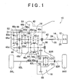
- FIG. 1 is a skeleton diagram useful for explaining the general construction of a vehicular drive system 10 to which the present invention is applied.
- the vehicular drive system 10 is adapted for a FF (front-engine, front-drive) vehicle, and includes an engine 12 as a driving source for running the vehicle, an automatic clutch 14, a transmission (synchromesh transmission) 16, and a differential gear unit 18.
- FF front-engine, front-drive
- the automatic clutch 14 is, for example, a dry single-plate friction clutch as shown in FIG. 2 , and includes a flywheel 22 mounted on a crankshaft 20 of the engine 12, a clutch disc 26 installed on a clutch output shaft 24, and a pressure plate 30 installed on a clutch cover 28.
- the automatic clutch 14 further includes a diaphragm spring 32 that biases the pressure plate 30 toward the flywheel 22 so as to sandwich the clutch disc 26 under pressure between the plate 30 and the flywheel 22 for power transmission, and a release sleeve 38 adapted to be moved leftward in FIG. 2 by a release fork 36 actuated by a clutch release cylinder 34, so as to displace the inner end portion of the diaphragm spring 32 leftward in FIG. 2 to release (or disengage) the clutch 14.
- the clutch release cylinder 34 functions as a clutch actuator for releasing or engaging the automatic clutch 14.
- the transmission 16 is installed, along with the differential gear unit 18, in a common housing 40, to provide a transaxle, such that the transmission 16 and the differential gear unit 18 are immersed in and lubricated by lubricating oil contained in a certain amount in the housing 40.
- the transmission 16 is a so-called constant mesh type parallel-shaft transmission, and a plurality of pairs of shift gears (gear pairs) 46a - 46e having different gear ratios are installed between two parallel shafts, namely, an input shaft 42 and an output shaft 44.
- Each of the shift gear pairs 46a - 46e consists of a first gear mounted on one of the two parallel shafts to be rotatable relative to the shaft, and a second gear mounted on the other of the two shafts such that it cannot rotate relative to the other shaft.
- the transmission 16 is further provided with a two-shaft mesh type transmission mechanism having a plurality of synchromesh clutches (synchromesh devices) 48a - 48e for coupling gears to be synchronized, i.e., the first gears, of the shift gear pairs 46a - 46e, selectively to the first shaft 42 or the output shaft 44.
- the transmission 16 further includes three clutch hub sleeves (engaging sleeves) 50a, 50b, 50c included in the synchromesh clutches 48a - 48e, and three parallel fork shafts 52 (only one of which is shown in FIG. 1 ) provided with three forks 51 (only one of which is shown in FIG. 1 ) that are engaged with the clutch hub sleeves 50a, 50b, 50c to be rotatable relative to the sleeves about the axis of the input shaft 42 or output shaft 44, so as to selectively move the clutch hub sleeves 50a, 50b, 50c in the axial direction of the input shaft 42 or output shaft 44, thereby to establish a selected one of gear positions of the transmission 16.
- the transmission 16 further includes a shift & selector shaft 59 installed in a direction substantially perpendicular to the above-mentioned fork shafts 52.
- the shift & selector shaft 59 is adapted to be mechanically moved in a selecting direction as an axial direction substantially perpendicular to the fork shafts 52, in accordance with the operation of a selector cylinder 76 (which will be described later, referring to FIG. 5 ) that functions as a selector actuator, to be engaged with a selected one of the three fork shafts 52.
- the shift & selector shaft 59 is also adapted to be rotated about the axis substantially perpendicular to the fork shaft 52 in this embodiment, for example, in accordance with the operation of a shift cylinder (hydraulic cylinder) 78 (which will be described later, referring to FIG. 5 ) that functions as a shift actuator, so as to move the fork shaft 52 in the axial direction thereof, thereby to establish a certain gear position of the transmission.
- a shift cylinder hydraulic cylinder
- a pair of reverse gears 54 are mounted on the input shaft 42 and the output shaft 44 such that these gears are not in mesh with each other.
- the transmission 16 is placed in a reverse gear position when a reverse-drive idle gear mounted on a countershaft (not shown) comes into mesh with the pair of reverse gears 54, respectively.
- the input shaft 42 is coupled to the clutch output shaft 24 of the automatic clutch 14 via a spline coupling or joint 55, and an output gear 56, which is mounted on the output shaft 44, meshes with a ring gear 58 of the differential gear unit 18.
- the differential gear unit 18 which is of a bevel gear type, has a pair of side gears 80R, 80L to which drive shafts 82R, 82L are respectively coupled by spline fitting, or the like, so that right and left front wheels (driving wheels of the vehicle) 84R, 84L are rotated or driven by the drive shafts 82R, 82L, respectively.
- FIG. 1 is an exploded view showing the axes of the input shaft 42, output shaft 44 and the ring gear 58 in the same plane.
- the shift & selector shaft 59 is actuated by the selector cylinder 76 to be engaged with a selected one of the three fork shafts 52, so as to be placed in one of three select positions in the selecting direction.
- the shift & selector shaft 59 is placed in one of a first select position in which the shaft 59 can engage with the clutch hub sleeve 50c via the corresponding fork shaft 52 and fork 51, a second select position in which the shaft 59 can engage with the clutch hub sleeve 50b, and a third select position in which the shaft 59 can engage with the clutch hub sleeve 50a.
- the shift & selector shaft 59 is actuated by the shift cylinder 78 to be rotated about the axis substantially perpendicular to the fork shafts 52, as described above, so as to be placed in one of three shift positions.
- the shift & selector shaft 59 is placed in one of a first shift position in which the clutch hub sleeve 50a, 50b, 50c is moved rightward in FIG. 1 via the corresponding fork shaft 52 and fork 51, to be engaged with one of the synchromesh clutches 48a, 48c, 48e, a second shift position in which the clutch hub sleeve 50b, 50c is moved leftward in FIG. 1 to be engaged with the synchromesh clutch 48b or 48d, and a neutral position in which none of the synchromesh clutches 48a - 48e is engaged, to provide a neutral condition.
- the synchromesh clutch 48b In the second shift position of the second shift position, the synchromesh clutch 48b is engaged so as to establish a fourth gear position G4 having the fourth largest speed ratio.
- the speed ratio of the fourth gear position G4 is substantially equal to 1.
- the synchromesh clutch 48a In the first shift position of the third select position, the synchromesh clutch 48a is engaged so as to establish a fifth gear position G5 having the smallest speed ratio.
- the reverse gear position is established.
- the selector cylinder 76 and shift cylinder 78 for moving the fork shafts 52 function as shift actuators for switching or changing the gear positions of the transmission 16 without requiring the driver's operating force or manipulations.
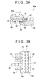
- the synchromesh clutch 48a includes the above-mentioned clutch hub sleeve 50a, a shifting key 62 that is engaged with the clutch hub sleeve 50a by a key spring 60, and a synchronizer ring 64 that is rotated along with the shifting key 62 about the axis of the input shaft 42 with a certain play provided between the synchronizer ring 64 and the shifting key 62.
- the synchromesh clutch 48a further includes engaging teeth 67 comprising outer teeth formed integrally on the input gear 66, or first gear, of the shift gear pair 46a, a coned portion 68 integral with the input gear 66, and a hub 69a (see FIG. 1 ) fixed to the input shaft 42.
- engaging teeth 67 comprising outer teeth formed integrally on the input gear 66, or first gear, of the shift gear pair 46a, a coned portion 68 integral with the input gear 66, and a hub 69a (see FIG. 1 ) fixed to the input shaft 42.
- spline teeth (inner teeth) 70 provided on the inner circumferential surface of the clutch hub sleeve 50a meshing or engaging with spline teeth (outer teeth) provided on the outer circumferential surface of the hub 69a
- the clutch hub sleeve 50a is arranged to constantly rotate as a unit with the input shaft 42 while being movable in the axial direction of the input shaft 42.
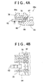
- the synchronizer ring 64 functions as a synchronizing ring for inhibiting movement of the clutch hub sleeve 50a by contacting with the inner teeth of the clutch hub sleeve 50a until the rotational speed of the input gear 66 becomes equal to that of the clutch hub sleeve 50, during the course of moving the clutch hub sleeve 50a (engaging sleeve) toward the engaging teeth 67 of the input gear 66. Then, as shown in FIGS. 4A, 4B , the spline teeth 70 of the clutch hub sleeve 50a come into mesh with spline teeth 72 provided on the synchronizer ring 64, and further into mesh with the engaging teeth 67 of the input gear 66.
- FIGS. 3A, 3B show an unengaged condition, or neutral condition, of the synchromesh clutch 48a
- FIGS. 4A, 4B show an engaged condition of the synchromesh clutch 48a
- FIG. 3A and FIG. 4A are cross-sectional views taken in one plane including the axis of the clutch 48a
- FIG. 3B and FIG. 4B are exploded views showing the conditions of FIG. 3A and FIG. 4A , respectively, except for a cylindrical portion of the clutch hub sleeve 50a, as viewed from the outer periphery of the clutch 48a.
- synchromesh clutches 48b - 48e have substantially the same construction as that of the synchromesh clutch 48a. It is, however, to be noted that the synchromesh clutches 48b and 48c share the clutch hub sleeve 50b, and the synchromesh clutches 48d and 48e share the clutch hub sleeve 50c.
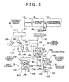
- FIG. 5 is a circuit diagram showing a hydraulic control circuit (HPU: Hydraulic Power Unit) 80 for controlling hydraulic pressures supplied to the clutch release cylinder 34, selector cylinder 76 and the shift cylinder 78.
- the hydraulic control circuit 80 includes an electric motor-driven oil-hydraulic pump 84 that feeds hydraulic fluid under pressure from a reservoir 81, an accumulator 84 that accumulates the hydraulic pressure, or line pressure Pa, supplied from the oil-hydraulic pump 84, and a three-port linear spool type clutch solenoid valve 92 adapted to be placed in a selected one of three positions, namely, a first position where the valve 92 connects an oil chamber 88 of the clutch release cylinder 34 to a main oil channel 89, a second position where the valve 92 disconnects the oil chamber 88 from the main oil channel 89, and a third position where the valve 92 connects the oil chamber 88 to a drain channel 90.
- HPU Hydraulic Power Unit
- the amount (or flow rate) of the hydraulic fluid flowing through the clutch solenoid valve 92 (or the cross-sectional area of the valve 92 through which the fluid flows) can be continuously controlled.
- the connecting (or engaging) speed (or the time required for engagement) can be set to an appropriate speed, according to shift conditions, such as the type of shifting (e.g., upshifting or downshifting), vehicle speed, and the engine speed.
- the hydraulic control circuit 80 also includes a three-port linear spool type linear solenoid valve (main control valve 94) for regulating the master pressure Pm to be applied to the selector cylinder 76 and shift cylinder 78, to a value commensurate with, for example, the input torque of the transmission 16 or the throttle opening.
- main control valve 94 three-port linear spool type linear solenoid valve
- the linear solenoid valve 94 is placed in a selected one of three operating states, namely, a connecting state in which the valve 94 connects the main oil channel 89 to the first oil channel 98, a shutoff state in which the valve 94 disconnects the first oil channel 98 from the main oil channel 89, and a drain state in which the valve 94 connects the first oil channel 98 to the drain channel 90 while disconnecting the first oil channel 98 from the main oil channel 89.
- the hydraulic control circuit 80 further includes an accumulator 100 provided in the first oil channel 98 between the linear solenoid valve 94 and the shift cylinder 78 and selector cylinder 76, for accumulating the hydraulic pressure supplied from the linear solenoid valve 84 while storing a certain amount of the hydraulic fluid, and supplying the stored hydraulic fluid to the shift cylinder 78 after the linear solenoid valve 94 disconnects the first oil channel 98 from the main oil channel 89.
- the hydraulic control circuit 80 further includes stroke sensor 102 and stroke sensor 104 for detecting the operating amounts or operating positions of the selector cylinder 76 and the shift cylinder 78, respectively.
- the hydraulic control circuit 80 further includes a relief valve 108, check valve 110, hydraulic pressure sensor 112 for detecting the line pressure Pa of the hydraulic fluid, hydraulic pressure sensor 113 for detecting the original pressure Pm applied to the selector cylinder 76 and shift cylinder 78, and a strainer 114.
- the linear solenoid valve 94 serving as a control valve supplies the hydraulic fluid to the shift cylinder 78 until one of the synchromesh clutches 48a - 48e, which has been engaged to establish the current gear position, is disengaged and brought into a neutral condition.
- the linear solenoid valve 94 shuts off or stops supply of the hydraulic fluid to the selector cylinder 76 and the shift cylinder 78 when one of the synchromesh clutches 48a - 48e to be engaged for shifting is in a neutral condition in which the shift cylinder 78 is placed at a predetermined operating position before the clutch hub sleeve 50a starts pressing the synchronizer ring 64, prior to a start of engaging of the clutch hub sleeve 50 with the engaging teeth 67, namely, prior to a start of the push-in stroke of the clutch hub sleeve 50.
- the predetermined operating position of the shift cylinder 78 is set to the neutral position of the shift spring 78.
- the neutral position is set at an intermediate position between a position at which the synchronizer ring 64 starts being pressed at one side on the shift stroke of the shift cylinder 78 corresponding to the above-indicated first shift position, and a position at which the synchronizer ring 64 starts being pressed at the other side corresponding to the above-indicated second shift position.
- the accumulator 100 which is a spring loaded accumulator, has a main body 116 in the form of a cylindrical container, an accumulator piston 120 that is slidably fitted in the main body 116 and forms a variable-volume oil chamber 118, and a spring 122 provided on one side of the accumulator piston 120 opposite to the oil chamber 118, for exerting spring force on one face of the accumulator piston 120 to bias the same toward the oil chamber 118.
- the selector cylinder 76 which is a double-acting hydraulic cylinder, has a cylindrical main body or cylinder body 124, a piston 126 slidably fitted in the cylinder body 124, a rod 128 that is joined at one end to the piston 126 and protrudes from the cylinder body 124 to the outside, and first oil chamber 130 and second oil chamber 132 formed in the cylinder body 124 on the opposite sides of the piston 126 such that a part of the rod 128 is located in the first oil chamber 130.
- the piston 126 is biased by a spring (not shown) toward a neutral position corresponding to the second select position of the shift & selector shaft 59.
- a first pressure-receiving area Aa1 of one end face of the piston 126 which faces the first oil chamber 130 is equal to one half of a second pressure-receiving area Aa2 of the other end face of the piston 126 which faces the second oil chamber 132.
- the shift cylinder 78 which is a double-acting hydraulic cylinder, has a cylindrical main body or cylinder body 134, a piston 136 slidably fitted in the cylinder body 134, a rod 138 that is joined at one end to the piston 136 and protrudes from the cylinder body 134 to the outside, and first oil chamber 140 and second oil chamber 142 formed in the cylinder body 134 on the opposite sides of the piston 136 such that a part of the rod 138 is located in the first oil chamber 140.
- the piston 136 is biased by a spring (not shown) toward a neutral position corresponding to the neutral position of the shift & selector shaft 59.
- a first pressure-receiving area Ab1 of one end face of the piston 136 of the shift cylinder 76 which faces the first oil chamber 140 is equal to one half of a second pressure-receiving area Ab2 of the other end face of the piston 136 which faces the second oil chamber 142.
- the selector stroke sensor 102 is connected to the rod 128 of the selector cylinder 76, and functions as a selector stroke detector for detecting the position or distance to/over which the shift & selector shaft 59 is moved in the selecting direction, i.e., in the direction substantially perpendicular to the axial direction of the fork shaft 52, with reference to the neutral position of the selector cylinder 76, for example.
- the shift stroke sensor 104 is connected via a link mechanism (not shown) to the rod 138 of the shift cylinder 78, and functions as a shift stroke detector for detecting the position or amount to/by which the shift & selector shaft 59 is rotated about the axis of the above-indicated selecting direction, with reference to, for example, the neutral position of the shift cylinder 78. In this manner, the shift stroke sensor 104 detects the position or distance to/over which the fork shaft 52 is moved in a direction parallel to the axis of the input shaft 42, with reference to the above-mentioned neutral condition.
- Each of the selector stroke sensor 102 and shift stroke sensor 104 consists of, for example, a potentiometer, a magnetic scale, or the like.
- the potentiometer includes a fixed resistor, and a brush that is moved with the rod 128, 138 while being in sliding contact with the fixed resistor, and is adapted to produce a voltage output proportional to the moving distance or amount of rotation of the shift & selector shaft 59.
- the magnetic scale includes a fixed member having a specified number of magnetized regions per unit distance in one direction, and a magnetic head that is moved in this direction relative to the fixed member while being located close to the fixed member, and is adapted to generate a pulse signal of which the number of pulses corresponds to the above-mentioned moving distance or amount of rotation of the shift & selector shaft 59.
- the first oil channel 98 is connected to the first oil chambers 130, 140 of the selector cylinder 76 and the shift cylinder 78, and a second oil channel 144, which diverges from the first oil channel 98, is connected to the second oil chambers 132, 142 of the selector cylinder 76 and the shift cylinder 78.
- the hydraulic control circuit 80 further includes a selector solenoid valve (switching control valve) 146 and a shift solenoid valve (switching control valve) 148, which are provided in the second oil channel 144.
- the selector solenoid valve 146 is placed in a selected one of three operating states, i.e., a first connecting state in which the second oil chamber 132 of the selector cylinder 76 is connected to the first oil channel 98 via the second oil channel 144, a shutoff state in which the second oil chamber 132 is disconnected from the first oil channel 98, and a second connecting state in which the second oil chamber 132 is connected to the drain channel 90.
- the shift solenoid valve 148 is placed in a selected one of three operating states, i.e., a first connecting state in which the second oil chamber 142 of the shift cylinder 78 is connected to the first oil channel 98 via the second oil channel 144, a shutoff state in which the second oil chamber 142 is disconnected from the first oil channel 98, and a second connecting state in which the second oil chamber 142 is connected to the drain channel 90.
- FIG. 6 which shows a part of the hydraulic control circuit 80 of FIG. 5 , illustrates a condition in which the clutch hub sleeve 50b of the synchromesh clutch 48 that is in a neutral condition is moved to a position corresponding to the second shift position, namely, the rod 138 (piston 136) of the shift cylinder 78 is moved toward the second oil chamber 142 (in the direction of the left-pointing arrow in FIG. 6 ).
- the linear solenoid valve 94 and the selector solenoid valve 146 are in the shutoff states, and the shift solenoid valve 148 is in the second connecting state.
- FIG. 7 which shows a part of the hydraulic control circuit 80 of FIG.
- FIG. 5 illustrates a condition in which the clutch hub sleeve 50b of the synchromesh clutch 48 that is in a neutral condition is moved to a position corresponding to the first shift position, namely, the rod 138 (piston 136) of the shift cylinder 78 is moved toward the first oil chamber 140 (in the direction of the right-pointing arrow in FIG. 7 ).
- the linear solenoid valve 94 and the selector solenoid valve 146 are in the shutoff states, and the shift solenoid valve 148 is in the first connecting state.
- FIG. 7 illustrates a condition of the hydraulic control circuit 80 at time t4 in the time chart of FIG. 9 which will be described later.
- the hydraulic fluid is supplied to the first oil chamber 140 when the shift cylinder 78 is operated from the neutral position to the second shift position, as shown in FIG. 6
- the hydraulic fluid is supplied to the first oil chamber 140 and the second oil chamber 142 when the shift cylinder 78 is operated from the neutral position to the first shift position, as shown in FIG. 7 .
- the first pressure-receiving area Ab1 of one end face of the piston 136 of the shift cylinder 78 which faces the first oil chamber 140 is equal to one half of the second pressure-receiving area Ab2 of the other end face that faces the second oil chamber 142.
- the same hydraulic pressure can be obtained after the operation of the shift cylinder 78 if the operating amount, or operating stroke, of the shift cylinder 78 is the same, irrespective of which (forward or backward) direction in which the shift cylinder 78 is operated, due to the balance between the spring force of the spring (not shown) and the force applied from the hydraulic fluid to the piston 136.
- FIG. 8 which shows a part of the hydraulic control circuit 80 of FIG. 5 , illustrates a condition of the hydraulic control circuit 80 at the time of shifting of the transmission 16.
- the synchromesh clutch 48 that has been engaged to establish the gear position prior to the shifting is released and brought into a neutral condition
- the synchronizer ring 64 of the synchromesh clutch 48b for example, which is to be engaged to establish the gear position after the shifting, starts a synchronizing operation for engagement of the clutch 48b, as shown in FIG. 8.
- FIG. 8 illustrates a condition of the hydraulic control circuit 80 at time t5 in the time chart of FIG. 9 which will be described later.
- two-dot chain lines indicated in the accumulator 100 represent the position of the accumulator piston 120 in the condition of FIG. 7
- Ac[mm 2 ] is the cross-sectional area of the oil chamber 118 of the accumulator 100, namely, the cross-sectional area of the piston 120
- two-dot chain lines indicated in the shift cylinder 78 represent the position of the piston 136 in FIG. 7 , namely, the neutral position of the piston 136
- y[mm] is the operating amount, or displacement, of the piston 136 that is operated from the time when the linear solenoid valve 94 is brought into in a shutoff state while the shift cylinder 78 is in the neutral condition, to the time when the synchronizing operation is started.
- the accumulator 100 is able to control the master pressure Pm [Pa] of the first oil channel 98 at the downstream of the linear solenoid valve 94, by controlling the amount Q [mm 3 ] of the hydraulic fluid that passes through the linear solenoid valve 94.
- the spring loaded accumulator 100 used in this embodiment has characteristics as represented by Equations (1) through (5) as follows.
- Pm Pa Q mm 3 / C mm 3 / Pa
- F N k N / mm ⁇ x mm
- Pm Pa F N / Ac mm 2
- V[mm 3 ] in Equation (2) is the integral of the flow amount Q [mm 3 ], namely, the total amount of the hydraulic fluid that has passed through the linear solenoid valve 94.
- k [N/mm] is the spring constant of the spring 122 of the spring loaded accumulator 100
- x [mm] is the displacement of the spring 122 relative to its free length.
- F [N] in Equation (4) which is indicated by an arrow in FIG. 8 , is the reaction force of the spring 122 applied to the accumulator piston 120, against the hydraulic pressure supplied into the oil chamber 118.
- the compliance C [mm 3 /Pa] in Equation (1) above is a value that is determined as appropriate according to the shift time or period and the performance of the linear solenoid valve 94, within the range between the minimum compliance Cmin [mm 3 /Pa] represented by Equation (6) below, and the maximum compliance Cmax [mm 3 /Pa] represented by Equation (7) below.
- the compliance C which represents the performance of the accumulator 100, is a value (volume/pressure) obtained by dividing the volume of the hydraulic fluid flowing into or flowing out of the accumulator 100 by a difference between the pressures measured before and after the hydraulic fluid flows into or out of the accumulator 100.
- the maximum compliance Cmax is a value that satisfies a condition that engagement of the clutch hub sleeve 50a with the engaging teeth 67 after start of the synchronizing operation, or the push-in stroke, is completed even when no hydraulic fluid is supplied from the linear solenoid valve 94, i.e., no feed-forward control is performed, and a condition that the master pressure Pm is not reduced to around zero when the engagement is completed. If the linear solenoid valve 94 assures high performance, namely, has a high capability of quickly regulating the hydraulic pressure to a certain target pressure with feed-forward control appropriately performed, the above-mentioned maximum compliance Cmax is set to a small value.
- Cmin mm 3 / Pa ⁇ V mm 3 / ⁇ P Pa
- Cmax mm 3 / Pa Qsh mm 3 ⁇ Td 1 / Pa
- ⁇ P is a pressure difference between a first hydraulic pressure Pm1 [Pa] supplied to the shift cylinder 78 that operates the clutch hub sleeve 50 when disengaging the synchromesh clutch 48 that has been engaged to establish the gear position prior to shifting of the transmission, and a second hydraulic pressure Pm2 [Pa] supplied to the shift cylinder 78 when the synchronizer ring 64 of the synchromesh clutch 48 that is to be engaged to establish the gear position after the shifting starts a synchronizing operation so as to engage the synchromesh clutch 48.
- Equation (6) ⁇ V, which is represented by Equation (8) below, is the amount of the hydraulic fluid consumed by the shift cylinder 78 during shifting from the time when the synchromesh clutch 48 is placed in the neutral condition to the start of the synchronizing operation.
- a [mm 2 ] is the cross-sectional area defined by the inner circumference of the main body 134 of the shift cylinder 78, which is substantially equal to the second pressure-receiving area Ab2.
- ⁇ V mm 3 A mm 2 ⁇ y mm
- Equation (7) Qsh [mm 3 ] is the maximum amount of the hydraulic fluid that passes through the shift solenoid valve 148 to be supplied to the shift cylinder 78 during the shifting, from the time when the synchromesh clutch 48 is in the neutral condition to the time when the synchromesh clutch 48 to be engaged to establish the gear position after the shifting is engaged.
- Td[1/Pa] is a response delay value that is set in relation to the performance of the linear solenoid valve 94, and is set to a smaller value as the performance of the valve 94 is higher.
- the accumulator 100 is designed so as to satisfy the above-indicated Equations (1) through (8).
- the pressure to be applied to the synchronizer ring 64, or the above-indicated second hydraulic pressure Pm2 is initially determined from the desired load (allowable load) to be applied to the synchronizer ring 64 during the synchronizing operation, and dimensions of respective parts, and so forth, are determined.
- FIG. 9 illustrates upshifting from the second gear position G2 to the third gear position G3 by way of example.
- the master pressure Pm applied from the linear solenoid valve 94 to the selector cylinder 76 and the shift cylinder 78, the stroke position of the shift cylinder 78 and the stroke position of the selector cylinder 76 are plotted on the same time axis.
- an operation to release the automatic clutch 14 is started in response to a request for shifting made through the operator's manipulation of the shift lever, for example.
- the linear solenoid valve 94 that was in the drain state before time t1 is brought into the connecting state, and the master pressure Pm applied from the linear solenoid valve 94 to the selector cylinder 76 and the shift cylinder 78 starts being regulated to Pm1.
- the selector solenoid valve 146 and the shift solenoid valve 148 are held in the shutoff states. In a period between time t1 and time t2, the operation to release the automatic clutch 14 is completed.
- the shift cylinder 78 is in the neutral position detected based on the operating amount of the shift cylinder 78 measured by the stroke sensor 104, namely, the synchromesh clutch 48 is in a neutral condition.
- the selector solenoid valve 146 is brought into the second connecting state at time t3, and the selector cylinder 76 is placed in the second select position by time t4.
- the selector solenoid valve 146 and the linear solenoid valve 94 are brought into the shutoff states, as shown in FIG. 7 , and the master pressure Pm is automatically reduced from Pm1 to Pm2 as the shift cylinder 76 is moved from the neutral position to a so-called balk position at which the synchronizer ring 64 starts a synchronizing operation.
- the shift cylinder 76 is placed in the balk position as shown in FIG. 8 , and the synchronizing operation of the synchronizer ring 64 is started.
- the synchronizing operation is completed at time t6, and the spline teeth 70 of the clutch hub sleeve 50b are brought into mesh with the spline teeth 72 of the synchronizer ring 64 and the engaging teeth 67 of the input gear 66 by time 7, so that engagement of the synchromesh clutch is completed.
- the hydraulic control circuit 80 of the vehicular synchromesh transmission 16 of this embodiment includes the linear solenoid valve 94 and the accumulator 100.
- the linear solenoid valve 94 supplies a hydraulic pressure to the shift cylinder 78 until one of the synchromesh clutches 48a - 48c, which has been engaged, is disengaged and brought into a neutral condition, and shuts off or stops supply of the hydraulic pressure to the selector cylinder 76 and the shift cylinder 78 when one of the synchromesh clutches 48a-48e is in a neutral condition before the clutch hub sleeve 50a starts pressing the synchronizer ring 64, prior to a start of engagement of the clutch hub sleeve 50a with the engaging teeth 67, i.e., a start of the push-in stroke.
- the accumulator 100 which is provided in the first oil channel 98 between the linear solenoid valve 94 and the shift cylinder 78, stores a certain amount of hydraulic fluid while accumulating the hydraulic pressure supplied from the linear solenoid valve 94, and supplies the stored hydraulic fluid to the shift cylinder 78 after the linear solenoid valve 94 is shut off.
- the hydraulic pressure is supplied from the accumulator 100 to the shift cylinder 78 after the supply of the hydraulic pressure from the linear solenoid valve 94 to the shift cylinder 78 is shut off.
- the hydraulic pressure, or the master pressure Pm, supplied from the accumulator 100 is reduced from the first oil pressure Pm1 to the second oil pressure Pm2 according to the amount of the hydraulic fluid supplied from the accumulator 100.
- the shift cylinder 78 is a double-acting hydraulic cylinder having the cylinder body 134, piston 136 slidably fitted in the cylinder body 134, rod 138 that is joined at one end to the piston 136 and protrudes from the cylinder body 134 to the outside, and the first oil chamber 140 and second oil chamber 142 formed on the opposite sides of the piston 136 within the cylinder body 134 such that a part of the rod 138 is located in the first oil chamber 140.
- the hydraulic control circuit 80 further includes the stroke sensor 104 for detecting the operating amount or operating position of the shift cylinder 78.
- the linear solenoid valve 94 is arranged to shut off supply of the hydraulic pressure to the shift cylinder 78 when the shift cylinder 78 is placed at the predetermined operating position, based on the operating amount or operating position detected by the stroke sensor 104. Accordingly, the hydraulic pressure is supplied from the accumulator 100 to the shift cylinder 78, after the supply of the hydraulic pressure from the linear solenoid valve 94 to the shift cylinder as a hydraulic cylinder is shut off when the shift cylinder 78 is placed at the predetermined operating position, based on the operating amount detected by the stroke sensor 104. Also, the hydraulic pressure supplied from the accumulator 100 is reduced in accordance with the amount of the hydraulic fluid thus supplied. Therefore, when the synchromesh clutch 48a - 48e that has been in a neutral condition starts a synchronizing operation, a hydraulic pressure having an appropriate level is generated to the shift cylinder 78 without delay.
- the first oil channel 98 is connected to the first oil chamber 140 of the shift cylinder 78, and the shift solenoid valve 148 is further provided in the second oil channel 144 that diverges from the first oil channel 98 and is connected to the second oil chamber 142 of the shift cylinder 78.
- the shift solenoid valve 148 is placed in a selected one of the three states, i.e., the first connecting state in which the second oil chamber 142 is connected to the first oil channel 98, the shutoff state in which the second oil chamber 142 is disconnected from the first oil channel 98, and the second connecting state in which the second oil chamber 142 is connected to the drain channel 90.
- the first pressure-receiving area Ab1 of one face of the piston 136 which faces the first oil chamber 140 is equal to one half of the second pressure-receiving area Ab2 of the other face of the piston 136 which faces the second oil chamber 142.
- the shift cylinder 78 can be appropriately operated in either of the above-indicated two directions.
- the accumulator 100 is a spring loaded accumulator having the container-like main body 116, accumulator piston 120 that is slidably fitted in the main body 116 and forms the variable-volume oil chamber 118, and the spring 122 that exerts spring force on one face of the accumulator piston 120 to bias the piston 120 toward the accumulator oil chamber 118.
- the hydraulic pressure accumulated in the spring loaded accumulator 100 and the amount of the hydraulic fluid stored in the accumulator 100 are determined by the characteristics of the spring 122, which advantageously makes it easy to design the accumulator 100.
- each of the shift gear pairs 46a - 46e consists of the input gear 66, or the first gear, which is mounted on one of the two parallel shafts, i.e., the input shaft 42 and the output shaft 44, such that the first gear is rotatable relative to the one shaft, and the second gear mounted on the other of the two parallel shafts such that the second gear cannot rotate relative to the other shaft.
- Each of the synchromesh clutches 48a - 48e includes (a) the engaging teeth 67 comprising the outer teeth formed integrally on the input gear 66, (b) the hub 69a, 69b, 69c fixed to one of the two parallel shafts, (c) the cylindrical clutch hub sleeve 50a, 50b, 50c having inner teeth that mesh with the outer teeth of the hub 69a, 69b, 69c and is actuated by the shift cylinder 78 in the axial direction of one of the two parallel shafts, and (d) the synchronizer ring 64 that contacts with the inner teeth of the clutch hub sleeve 50 so as to inhibit further movement of the clutch hub sleeve 50 until the rotational speed of the engaging teeth 67 becomes equal to that of the clutch hub sleeve 50a, 50b, 50c, during movement of the clutch hub sleeve 50a, 50b, 50c toward the engaging teeth 67.
- the compliance C obtained by dividing the volume of the hydraulic fluid flowing into or out of the accumulator 100 by the difference between the pressures measured before and after the hydraulic fluid flow into or out of the accumulator 100 is set to a value obtained, upon shifting, by dividing the amount ⁇ V of the hydraulic fluid consumed from the time when the shift cylinder 78 is placed at the predetermined operating position to the time when the synchronizing operation is started, by the pressure difference ⁇ P between the first oil pressure Pm1 supplied to the shift cylinder 78 when it actuates the clutch hub sleeve 50 so as to release the synchromesh clutch 48 that has been engaged to establish the gear position before the shifting, and the second oil pressure Pm2 supplied to the shift cylinder 78 when the synchronizer ring 64 of the synchromesh clutch 48 that is to be engaged to establish the gear position after the shifting starts a synchronizing operation so as to engage the synchromesh clutch 48.
- the hydraulic pressure is supplied from the accumulator 100 to the shift cylinder 78, and the hydraulic pressure thus supplied is naturally reduced in accordance with the amount of the hydraulic fluid thus supplied, down to the second oil pressure Pm as a preset target value. Therefore, when the clutch hub sleeve 50 of the synchromesh clutch 48 that has been in a neutral position is pressed against the synchronizer ring 64, namely, when synchronization by the synchromesh clutch 48 is started, the hydraulic pressure having a further appropriate level can be generated to the shift cylinder 78 without delay.
- the above-mentioned predetermined operating position of the shift cylinder 78 is the position at which the synchromesh clutch 48a - 48e is disengaged or released on the shift stroke thereof and is thus placed in a neutral condition.
- the hydraulic pressure is supplied from the accumulator 100 to the shift cylinder 78, and the hydraulic pressure, or the master pressure Pm, supplied from the accumulator 100 is reduced from the first oil pressure Pm1 to the second oil pressure Pm2, in accordance with the amount of the hydraulic fluid thus supplied.
- the driving system of the vehicle is of the FF (front-engine, front-drive) type in the illustrated embodiment
- the invention is not limitedly applied to this type of driving system, but may be favorably applied to vehicles of various driving systems.
- the transmission 16 is a constant mesh type transmission having some gear positions and including two parallel shafts in the illustrated embodiment, the transmission may include three or more shafts. Also, the transmission may be in various other forms; for example, not every gear position needs to be established through engagement of a constant mesh clutch.
- the invention may be applied to the case of downshifting as well as upshifting, and may also be applied to the case of shifting to a gear position that is higher or lower by two steps than the previous gear position, for example, shifting from the second gear position G2 to the fourth gear position G4, as well as shifting by one step.
- each of the synchromesh clutches 48a - 48e is of a synchromesh type having the synchronizer ring 64 in the illustrated embodiment, the invention may be applied to other types of clutches.
- accumulator 100 is a spring loaded accumulator in the illustrated embodiment, an accumulator of another type may be used.
- a hydraulic control circuit of a vehicular synchromesh transmission includes a linear solenoid valve (94) that supplies a hydraulic pressure to a shift cylinder (78) until one of a plurality of synchromesh clutches (48) is placed in a neutral condition, and shuts off the supply before a synchronizing operation is started, and an accumulator (100) provided in a first oil channel (98) between the linear solenoid valve (94) and the shift cylinder (78).
- the accumulator (100) stores a certain amount of hydraulic fluid while accumulating a hydraulic pressure, and functions as a hydraulic pressure source after the linear solenoid valve (94) is shut off.
- the hydraulic pressure' supplied from the accumulator (100) after the shutoff is reduced in accordance with the amount of the hydraulic fluid supplied from the accumulator (100), and a hydraulic pressure of an appropriate level is generated to the shift cylinder (78) without delay when the synchronizing operation of the synchromesh clutch (48) is started.
Landscapes
- Engineering & Computer Science (AREA)
- General Engineering & Computer Science (AREA)
- Mechanical Engineering (AREA)
- Control Of Transmission Device (AREA)
- Gear-Shifting Mechanisms (AREA)
Applications Claiming Priority (1)
| Application Number | Priority Date | Filing Date | Title |
|---|---|---|---|
| JP2008006324A JP4420112B2 (ja) | 2008-01-15 | 2008-01-15 | 車両用同期噛合式変速機の油圧制御回路 |
Publications (3)
| Publication Number | Publication Date |
|---|---|
| EP2080937A2 true EP2080937A2 (de) | 2009-07-22 |
| EP2080937A3 EP2080937A3 (de) | 2012-01-25 |
| EP2080937B1 EP2080937B1 (de) | 2013-02-27 |
Family
ID=40547910
Family Applications (1)
| Application Number | Title | Priority Date | Filing Date |
|---|---|---|---|
| EP09150529A Ceased EP2080937B1 (de) | 2008-01-15 | 2009-01-14 | Hydraulische Steuerschaltung eines Fahrzeugsynchrongetriebes |
Country Status (2)
| Country | Link |
|---|---|
| EP (1) | EP2080937B1 (de) |
| JP (1) | JP4420112B2 (de) |
Cited By (5)
| Publication number | Priority date | Publication date | Assignee | Title |
|---|---|---|---|---|
| CN103988003A (zh) * | 2011-08-02 | 2014-08-13 | 技术推进公司 | 变速箱的液压控制装置、方法和相关的变速箱 |
| EP2647883A3 (de) * | 2012-04-07 | 2017-09-13 | Volkswagen Aktiengesellschaft | Hydraulische Steuerungsvorrichtung |
| CN107882930A (zh) * | 2017-11-06 | 2018-04-06 | 浙江中谷车桥有限公司 | 无离合器电动车机电一体化自动变速箱 |
| EP3450786A1 (de) * | 2017-08-30 | 2019-03-06 | Toyota Jidosha Kabushiki Kaisha | Leistungsübertragungsvorrichtung für fahrzeug |
| DE102014105281B4 (de) | 2013-07-11 | 2023-02-02 | Hyundai Motor Company | Ölpumpensystem eines Hybridfahrzeugs und Verfahren zum Steuern desselben |
Families Citing this family (1)
| Publication number | Priority date | Publication date | Assignee | Title |
|---|---|---|---|---|
| JP7099410B2 (ja) * | 2019-06-28 | 2022-07-12 | トヨタ自動車株式会社 | 同期噛合機構の制御装置 |
Citations (1)
| Publication number | Priority date | Publication date | Assignee | Title |
|---|---|---|---|---|
| JP2004293704A (ja) | 2003-03-27 | 2004-10-21 | Aisin Seiki Co Ltd | 自動変速機の油圧制御装置 |
Family Cites Families (2)
| Publication number | Priority date | Publication date | Assignee | Title |
|---|---|---|---|---|
| US5083646A (en) * | 1989-08-07 | 1992-01-28 | Kabushiki Kaisha Toyoda Jidoshokki Seisakusho | Hydraulic device for operating a clutch in an industrial vehicle |
| GB0024999D0 (en) * | 2000-10-12 | 2000-11-29 | Luk Lamellen & Kupplungsbau | Hydraulic actuation systems |
-
2008
- 2008-01-15 JP JP2008006324A patent/JP4420112B2/ja not_active Expired - Fee Related
-
2009
- 2009-01-14 EP EP09150529A patent/EP2080937B1/de not_active Ceased
Patent Citations (1)
| Publication number | Priority date | Publication date | Assignee | Title |
|---|---|---|---|---|
| JP2004293704A (ja) | 2003-03-27 | 2004-10-21 | Aisin Seiki Co Ltd | 自動変速機の油圧制御装置 |
Cited By (6)
| Publication number | Priority date | Publication date | Assignee | Title |
|---|---|---|---|---|
| CN103988003A (zh) * | 2011-08-02 | 2014-08-13 | 技术推进公司 | 变速箱的液压控制装置、方法和相关的变速箱 |
| CN103988003B (zh) * | 2011-08-02 | 2016-06-08 | 技术推进公司 | 变速箱的液压控制装置、方法和相关的变速箱 |
| EP2647883A3 (de) * | 2012-04-07 | 2017-09-13 | Volkswagen Aktiengesellschaft | Hydraulische Steuerungsvorrichtung |
| DE102014105281B4 (de) | 2013-07-11 | 2023-02-02 | Hyundai Motor Company | Ölpumpensystem eines Hybridfahrzeugs und Verfahren zum Steuern desselben |
| EP3450786A1 (de) * | 2017-08-30 | 2019-03-06 | Toyota Jidosha Kabushiki Kaisha | Leistungsübertragungsvorrichtung für fahrzeug |
| CN107882930A (zh) * | 2017-11-06 | 2018-04-06 | 浙江中谷车桥有限公司 | 无离合器电动车机电一体化自动变速箱 |
Also Published As
| Publication number | Publication date |
|---|---|
| EP2080937B1 (de) | 2013-02-27 |
| JP4420112B2 (ja) | 2010-02-24 |
| EP2080937A3 (de) | 2012-01-25 |
| JP2009168123A (ja) | 2009-07-30 |
Similar Documents
| Publication | Publication Date | Title |
|---|---|---|
| US6832978B2 (en) | Method of controlling a dual clutch transmission | |
| CN100476260C (zh) | 车辆用齿轮式变速机的控制装置、控制方法和控制系统 | |
| JP5211373B2 (ja) | 作業運搬車のデュアルクラッチ式変速装置 | |
| EP3217041B1 (de) | Schmierungssystem für kupplungsmechanismus | |
| US8874333B2 (en) | Control apparatus for automatic transmission | |
| EP2080937B1 (de) | Hydraulische Steuerschaltung eines Fahrzeugsynchrongetriebes | |
| US20090152070A1 (en) | Controller for automatic transmission | |
| US20040186645A1 (en) | Control apparatus and method for friction device of vehicle | |
| EP1190888A2 (de) | Fahrzeuggetriebesystem mit Antriebskupplung | |
| AU631824B2 (en) | Method and apparatus for controlling transmission | |
| US6878095B2 (en) | Automatic-clutch control system of automatic clutch type transmission | |
| JP4621969B2 (ja) | 自動変速機の制御装置 | |
| CN104903623A (zh) | 自动变速器的起步离合器控制装置 | |
| EP1508468B1 (de) | Steuerungsvorrichtung und -verfahren eines Schaltgetriebes | |
| JP4196629B2 (ja) | 自動変速機の油圧制御装置 | |
| JP5947070B2 (ja) | 変速機の制御装置 | |
| JPH09229179A (ja) | 油圧作動式変速機の制御装置 | |
| JP4770363B2 (ja) | 複数クラッチ式変速機の制御装置 | |
| CN111075923A (zh) | 车辆用动力传递装置的控制装置 | |
| JP4210564B2 (ja) | 車両用変速機の制御装置 | |
| JP2007198547A (ja) | 自動変速機の油圧制御装置 | |
| JP2021099106A (ja) | 車両用動力伝達装置の制御装置 | |
| JP2005076805A (ja) | 自動変速機 | |
| JPH0280846A (ja) | 圧力調整弁のオーバストローク防止装置 | |
| JPH0531693B2 (de) |
Legal Events
| Date | Code | Title | Description |
|---|---|---|---|
| PUAI | Public reference made under article 153(3) epc to a published international application that has entered the european phase |
Free format text: ORIGINAL CODE: 0009012 |
|
| 17P | Request for examination filed |
Effective date: 20090114 |
|
| AK | Designated contracting states |
Kind code of ref document: A2 Designated state(s): AT BE BG CH CY CZ DE DK EE ES FI FR GB GR HR HU IE IS IT LI LT LU LV MC MK MT NL NO PL PT RO SE SI SK TR |
|
| AX | Request for extension of the european patent |
Extension state: AL BA RS |
|
| REG | Reference to a national code |
Ref country code: DE Ref legal event code: R079 Ref document number: 602009013573 Country of ref document: DE Free format text: PREVIOUS MAIN CLASS: F16H0061000000 Ipc: F16H0061280000 |
|
| PUAL | Search report despatched |
Free format text: ORIGINAL CODE: 0009013 |
|
| AK | Designated contracting states |
Kind code of ref document: A3 Designated state(s): AT BE BG CH CY CZ DE DK EE ES FI FR GB GR HR HU IE IS IT LI LT LU LV MC MK MT NL NO PL PT RO SE SI SK TR |
|
| AX | Request for extension of the european patent |
Extension state: AL BA RS |
|
| RIC1 | Information provided on ipc code assigned before grant |
Ipc: F16H 61/00 20060101ALI20111219BHEP Ipc: F16H 61/28 20060101AFI20111219BHEP |
|
| GRAC | Information related to communication of intention to grant a patent modified |
Free format text: ORIGINAL CODE: EPIDOSCIGR1 |
|
| GRAP | Despatch of communication of intention to grant a patent |
Free format text: ORIGINAL CODE: EPIDOSNIGR1 |
|
| AKX | Designation fees paid |
Designated state(s): DE FR GB IT |
|
| GRAS | Grant fee paid |
Free format text: ORIGINAL CODE: EPIDOSNIGR3 |
|
| GRAA | (expected) grant |
Free format text: ORIGINAL CODE: 0009210 |
|
| AK | Designated contracting states |
Kind code of ref document: B1 Designated state(s): DE FR GB IT |
|
| RAP1 | Party data changed (applicant data changed or rights of an application transferred) |
Owner name: TOYOTA JIDOSHA KABUSHIKI KAISHA |
|
| REG | Reference to a national code |
Ref country code: GB Ref legal event code: FG4D |
|
| REG | Reference to a national code |
Ref country code: DE Ref legal event code: R096 Ref document number: 602009013573 Country of ref document: DE Effective date: 20130425 |
|
| PLBE | No opposition filed within time limit |
Free format text: ORIGINAL CODE: 0009261 |
|
| STAA | Information on the status of an ep patent application or granted ep patent |
Free format text: STATUS: NO OPPOSITION FILED WITHIN TIME LIMIT |
|
| 26N | No opposition filed |
Effective date: 20131128 |
|
| REG | Reference to a national code |
Ref country code: DE Ref legal event code: R097 Ref document number: 602009013573 Country of ref document: DE Effective date: 20131128 |
|
| REG | Reference to a national code |
Ref country code: DE Ref legal event code: R084 Ref document number: 602009013573 Country of ref document: DE |
|
| REG | Reference to a national code |
Ref country code: GB Ref legal event code: 746 Effective date: 20141023 |
|
| REG | Reference to a national code |
Ref country code: DE Ref legal event code: R084 Ref document number: 602009013573 Country of ref document: DE Effective date: 20141021 |
|
| REG | Reference to a national code |
Ref country code: FR Ref legal event code: PLFP Year of fee payment: 8 |
|
| REG | Reference to a national code |
Ref country code: FR Ref legal event code: PLFP Year of fee payment: 9 |
|
| REG | Reference to a national code |
Ref country code: FR Ref legal event code: PLFP Year of fee payment: 10 |
|
| PGFP | Annual fee paid to national office [announced via postgrant information from national office to epo] |
Ref country code: FR Payment date: 20211217 Year of fee payment: 14 Ref country code: GB Payment date: 20211206 Year of fee payment: 14 |
|
| PGFP | Annual fee paid to national office [announced via postgrant information from national office to epo] |
Ref country code: DE Payment date: 20211130 Year of fee payment: 14 |
|
| PGFP | Annual fee paid to national office [announced via postgrant information from national office to epo] |
Ref country code: IT Payment date: 20211213 Year of fee payment: 14 |
|
| REG | Reference to a national code |
Ref country code: DE Ref legal event code: R119 Ref document number: 602009013573 Country of ref document: DE |
|
| GBPC | Gb: european patent ceased through non-payment of renewal fee |
Effective date: 20230114 |
|
| PG25 | Lapsed in a contracting state [announced via postgrant information from national office to epo] |
Ref country code: GB Free format text: LAPSE BECAUSE OF NON-PAYMENT OF DUE FEES Effective date: 20230114 Ref country code: DE Free format text: LAPSE BECAUSE OF NON-PAYMENT OF DUE FEES Effective date: 20230801 |
|
| PG25 | Lapsed in a contracting state [announced via postgrant information from national office to epo] |
Ref country code: FR Free format text: LAPSE BECAUSE OF NON-PAYMENT OF DUE FEES Effective date: 20230131 |
|
| PG25 | Lapsed in a contracting state [announced via postgrant information from national office to epo] |
Ref country code: IT Free format text: LAPSE BECAUSE OF NON-PAYMENT OF DUE FEES Effective date: 20230114 |