EP2080612B2 - Verteilung von Punktlasten in Wabenverbundplatten - Google Patents
Verteilung von Punktlasten in Wabenverbundplatten Download PDFInfo
- Publication number
- EP2080612B2 EP2080612B2 EP09250096.6A EP09250096A EP2080612B2 EP 2080612 B2 EP2080612 B2 EP 2080612B2 EP 09250096 A EP09250096 A EP 09250096A EP 2080612 B2 EP2080612 B2 EP 2080612B2
- Authority
- EP
- European Patent Office
- Prior art keywords
- section
- panel
- plank
- honeycomb
- core
- Prior art date
- Legal status (The legal status is an assumption and is not a legal conclusion. Google has not performed a legal analysis and makes no representation as to the accuracy of the status listed.)
- Active
Links
- 239000002131 composite material Substances 0.000 claims description 30
- 239000007787 solid Substances 0.000 claims description 13
- 239000000463 material Substances 0.000 claims description 12
- 238000000034 method Methods 0.000 claims description 9
- 239000000853 adhesive Substances 0.000 claims description 8
- 230000001070 adhesive effect Effects 0.000 claims description 8
- 239000006260 foam Substances 0.000 claims description 6
- 238000004519 manufacturing process Methods 0.000 claims description 5
- 239000011347 resin Substances 0.000 claims description 4
- 229920005989 resin Polymers 0.000 claims description 4
- 239000003365 glass fiber Substances 0.000 claims 1
- 239000010410 layer Substances 0.000 description 5
- 238000010276 construction Methods 0.000 description 3
- 239000000835 fiber Substances 0.000 description 3
- 239000004677 Nylon Substances 0.000 description 2
- 239000011152 fibreglass Substances 0.000 description 2
- 238000005187 foaming Methods 0.000 description 2
- 238000009434 installation Methods 0.000 description 2
- 229920001778 nylon Polymers 0.000 description 2
- ISWSIDIOOBJBQZ-UHFFFAOYSA-N phenol group Chemical group C1(=CC=CC=C1)O ISWSIDIOOBJBQZ-UHFFFAOYSA-N 0.000 description 2
- 229920002430 Fibre-reinforced plastic Polymers 0.000 description 1
- 238000005452 bending Methods 0.000 description 1
- 230000015572 biosynthetic process Effects 0.000 description 1
- 238000010586 diagram Methods 0.000 description 1
- 239000011151 fibre-reinforced plastic Substances 0.000 description 1
- 239000000446 fuel Substances 0.000 description 1
- 210000000569 greater omentum Anatomy 0.000 description 1
- 239000011229 interlayer Substances 0.000 description 1
- 238000010030 laminating Methods 0.000 description 1
- 230000003071 parasitic effect Effects 0.000 description 1
- 239000011343 solid material Substances 0.000 description 1
- 239000010935 stainless steel Substances 0.000 description 1
Images


Classifications
-
- B—PERFORMING OPERATIONS; TRANSPORTING
- B32—LAYERED PRODUCTS
- B32B—LAYERED PRODUCTS, i.e. PRODUCTS BUILT-UP OF STRATA OF FLAT OR NON-FLAT, e.g. CELLULAR OR HONEYCOMB, FORM
- B32B3/00—Layered products comprising a layer with external or internal discontinuities or unevennesses, or a layer of non-planar shape; Layered products comprising a layer having particular features of form
- B32B3/10—Layered products comprising a layer with external or internal discontinuities or unevennesses, or a layer of non-planar shape; Layered products comprising a layer having particular features of form characterised by a discontinuous layer, i.e. formed of separate pieces of material
- B32B3/18—Layered products comprising a layer with external or internal discontinuities or unevennesses, or a layer of non-planar shape; Layered products comprising a layer having particular features of form characterised by a discontinuous layer, i.e. formed of separate pieces of material characterised by an internal layer formed of separate pieces of material which are juxtaposed side-by-side
-
- B—PERFORMING OPERATIONS; TRANSPORTING
- B64—AIRCRAFT; AVIATION; COSMONAUTICS
- B64C—AEROPLANES; HELICOPTERS
- B64C1/00—Fuselages; Constructional features common to fuselages, wings, stabilising surfaces or the like
- B64C1/06—Frames; Stringers; Longerons ; Fuselage sections
- B64C1/12—Construction or attachment of skin panels
-
- B—PERFORMING OPERATIONS; TRANSPORTING
- B64—AIRCRAFT; AVIATION; COSMONAUTICS
- B64C—AEROPLANES; HELICOPTERS
- B64C7/00—Structures or fairings not otherwise provided for
-
- Y—GENERAL TAGGING OF NEW TECHNOLOGICAL DEVELOPMENTS; GENERAL TAGGING OF CROSS-SECTIONAL TECHNOLOGIES SPANNING OVER SEVERAL SECTIONS OF THE IPC; TECHNICAL SUBJECTS COVERED BY FORMER USPC CROSS-REFERENCE ART COLLECTIONS [XRACs] AND DIGESTS
- Y10—TECHNICAL SUBJECTS COVERED BY FORMER USPC
- Y10T—TECHNICAL SUBJECTS COVERED BY FORMER US CLASSIFICATION
- Y10T428/00—Stock material or miscellaneous articles
- Y10T428/24—Structurally defined web or sheet [e.g., overall dimension, etc.]
- Y10T428/24149—Honeycomb-like
Definitions
- This disclosure generally relates to composite panels, especially those having honeycomb cores, and deals more particularly with a panel construction that is effective in distributing point loads, as well as a method for making the panels.
- Aerodynamic features on aerospace vehicles may be formed by lightweight composite panels that are attached to the vehicle airframe.
- aerodynamic pressure fairings are often formed from large, reinforced honeycomb panels that may be connected together and attached by struts to an airframe.
- thicker and/or higher density panels are required in order to react loads across the span, however these thicker panels increase the weight of the aircraft.
- US 5,346,367 describes a composite blade construction for a helicopter rotor blade using for the most part fiber reinforced plastic materials in which the major assembly of blade elements is a single step co-cure operation and in which an integral spar/skin carries centrifugal, flapwise and chordwise loads and also incorporates redundant means to carry torsional loads and a honeycomb core carries shear and aerodynamic pressures loads.
- the rotor blade includes a top integrated spar/skin and a bottom integrated spar/skin.
- a web extends span-wise at the mid portion of the blade and two honeycomb cores fill the blade internal area on either side of the web.
- EP 0,624,459 discloses a combination of a thin upper honeycomb core plus a lower honeycomb core of equal or lower density than the upper core which are united by only a thin light weight interlayer within two outer skins.
- the combination provides a low weight hybrid panel with increased durability when the upper surface is subjected to localized compressive loads.
- US 4,273,818 discloses a laminar panel assembly which is specified as particularly for use in space vehicles.
- the laminar panel assembly includes a first and second cover, a supporting core structure interposed between the cover layers and at least one force infeed element disposed within the core structure, the force infeed element including at least one solid central piece and shear webs extending therefrom.
- honeycomb panels described above may be attached to the airframe by composite laminates that are ramped down along the edges of the panel in order to allow attachment of the edges to the airframe by fasteners.
- ramping down the edges of the honeycomb panel to a solid laminate along the panel edges adds weight to the panel.
- the ramped down laminate section must be thicker in order to carry the load, thereby further adding to vehicle weight.
- Embodiments of the disclosure satisfy the need for lightweight, honeycomb panels capable of distributing point loads.
- Point loads applied to medial regions of the panel are distributed by a plank that is incorporated in the core and is bonded to or co-cured with a surrounding section of honeycomb.
- the increased strength and load distribution provided by the plank allows the panel to be at least partially supported by a strut connected between a supporting frame and medial regions of the panel.
- a composite panel comprises a core having first and second sides.
- the core includes a ring shaped first section of honeycomb material and a second section surrounded by and bonded to the ring shaped first section.
- the second section includes laminated plies of composite material forming an essentially solid plank, wherein said first section has a density less than the density of the second section.
- the core further includes a third core section of honeycomb material surrounding and being bonded to the first section of honeycomb material and having a density less than the density of the first section.
- the composite panel further includes laminated plies of composite material bonded to the first and second sides of the core and covering the solid plank.
- the first and second sections may be bonded by a foam adhesive.
- the panel may further comprise means for attaching a support to the panel in the area of the section of solid material.
- the composite panel may be used for aerospace vehicles.
- the laminated plies may include doubler plies overlying the first core section.
- the first core section may be located in a medial region of the panel and may be generally circular in shape.
- an airplane fairing comprises a panel as described above, wherein the second section is located in a medial region of the panel.
- the airplane fairing may further comprise a strut for supporting the panel and means for attaching the strut to the panel in the area of the plank.
- fabricating a composite panel for an aerospace vehicle comprises: making a plank from laminated plies of composite material; forming a core by surrounding the plank with a ring shaped first honeycomb section and surrounding the first honeycomb section with a third core section of honeycomb material, wherein the density of the first honeycomb section is less than the density of the plank and wherein the density of the third core section is less than the density of the first honeycomb section, and co-curing or co-bonding the plank, the first honeycomb section and the third core section; forming a layup by placing layers of composite material on opposite sides of the core; compacting the layup; and, curing the layup.
- the plank may be fabricated by laminating plies of fiber reinforced resin. Bonding the honeycomb layer to the plank may be performed by introducing an adhesive foam between the sides of the honeycomb layer and the sides of the plank.
- the method may further comprise installing a strut attachment on the panel in the area of the plank.
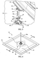
- an aircraft fairing generally indicated by the numeral 20 may include one or more lightweight, composite panels 22 fastened along their peripheries to a supporting frame 24.
- the frame 24 may, in turn, be attached as by struts 26 to the aircraft's airframe (not shown).
- Medial regions 28 of the panel 22 are supported on the frame member 24a ( FIGS. 2 and 3 ) by a strut-like, rigid link 26a.
- the attachment of the link 26a to the medial regions 28 of the panel 22 also results in less deflection or pillowing of the panel 22, which in turn reduces parasitic drag from the fairing 20, thereby improving fuel economy.
- the medial region 28 of the panel 22 is reinforced by a solid laminate plank 56 which functions to transfer pressure loads out of the panel 22 in order to provide moment continuity, and efficiently allow the link 26a to remove transverse shear loads from the panel 22.
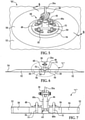
- the link 26a includes clevises 32, 34 and pins 36, 38 at its opposite ends.
- Pins 36, 38 may pass through spherical bearings 35 which connect the link 26a between an attachment fitting 40 and a panel attachment assembly 44.
- the attachment fitting 40 may in turn be secured to the frame member 24a by an angle adaptor 42 which effectively adjusts the position of the axis of the pin 36 relative to the frame member 24a.
- the spherical bearings 35 allow the fairing 20 to move along multiple axes relative to the frame member 24a, thus allowing the fairing 20 to flex somewhat in response to airflow loads and fuselage motion.
- the adjustable panel attachment fitting assembly 44 includes a nut plate 48 that is secured to the inboard face of the panel 22 by fastener bolts 51 which pass through the panel 22 and are held by threaded retainer nuts 50.
- a threaded eyebolt 46 is connected to the link 26a by the pin 38 and clevis 34, and is threadably received within a threaded, cylindrical body 48a forming part of the nut plate 48.
- removal of the bolts 51 allows the nut plate 48 to be rotated in either of two rotational directions, in order to adjust the axial position of the link 26a.
- the fastener bolts 51 pass through four through-holes 86 in the panel 22 which surround a central, countersunk through-hole 60.
- a sleeve 88 which may comprise, for example a corrosion resistant steel, is bonded or swaged within the central through-hole 60.
- the lower end 48b of the cylinder 48a passes through the sleeve 88 and includes a key-like opening 48c that is adapted to receive the end of a tool 90.
- rotation of the tool 90 likewise results in the rotation of the nut plate 48, thereby axially displacing the eyebolt 46 as well as the link 26a.
- Rotation of the nut plate 48 allows a shimless installation and fastener alignment. Since the nut plate 48 is threadably held on the end of the eyebolt 46, the nut plate 48 remains fastened to the link 26a when the fairing 20 is removed for servicing or other purposes.
- the use of the panel attachment fitting assembly 44 allows the fairing panel 20 to be removed and reinstalled without requiring access to the inside of the fairing 20.
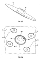
- a circular cover 90 is provided, which may be formed of a flexible, but durable material such as nylon.
- the cover 90 includes a tubular portion 92 that is received within sleeve 88.
- a retainer bolt 92 which also may comprise a nylon material, passes through the center of the cover 90 into the key-like opening 48c in order to hold the cover 90 against the outer surface of the panel 22.
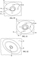
- point loads imposed on the panel 22 resulting from the attachment of the link 26a to medial regions 28 are laterally distributed through at least a portion of the panel 22.
- the medial regions 28 of the panel 22 are effectively reinforced by the plank 56 which forms part of the core 62 of the panel 22.
- the plank 56 may comprise, for example, a solid, rigid material formed by laminated plies of a composite material such as fiber reinforced resin, i.e., a solid laminate.
- the use of a plank 56 formed from a solid laminate allows the panel 22 to carry higher out-of-plane shear loads and bending loads compared to other types of core constructions.
- plank 56 is circular in shape and is slightly larger in diameter than the diameter of the nut plate 48.
- Other geometries, however, are possible, although a circular geometry aids in uniformly transferring moments in any radial direction through the plane of the panel 22.
- the solid plank 56 is effectively embedded in, and forms an integral part of the honeycomb panel core 62, enabling the link 26a or similar strut/tie-rod to be directly attached to the middle of the panel 22 while remaining capable of reacting large out-of-plane loads.
- the nut plate 48 can be directly attached to the plank 56 and then adjusted to fit against the panel 22 from outside of the fairing 20 using the adjustable panel attachment fitting 44.
- the plank 56 may be either precured or uncured (green) when it is inserted into the honeycomb panel core 62. The plank 56 is then co-cured with or co-bonded to the honeycomb core assembly 62 during fabrication of the panel 22.
- the core 62 further includes a ring shaped honeycomb section 58 surrounding and attached to the sides of the plank 56.
- the ring shaped honeycomb section 58 is surrounded by another honeycomb section 52.
- the density of the core section 58 is less than that of the plank 56 but greater than the density of the core section 52.
- the plank 56 comprises 60 laminated plies of fiberglass
- core section 58 comprises a heat resistant phenolic honeycomb having a density of eight pounds per cubic foot
- core section 52 is also a heat resistant phenolic honeycomb having a density of three pounds per cubic foot.
- the honeycomb core section 58 may be attached by co-curing plank 56 and core section 52 using a suitable foam adhesive which forms a splice 84 (see FIG. 8 ).
- FIG. 8 shows additional details of the layers that form the reinforced area 52 on the outer skin 54 of the panel 22.
- the core 62 formed by the co-bonded or co-cured plank 56 and honeycomb sections 52, 58 are sandwiched between laminated plies 64, 66 which may comprise any of various fiber reinforced resins, such as fiberglass.
- the laminated plies 64 may include multiple drop-off plies 70 sandwiched between full plies 68, 72.
- the outer group of laminated plies 66 may include drop-off plies 76 sandwiched between full plies 74, 78.
- the drop-off plies 70-76 in the region overlying the plank 56 and the high density honeycomb section 58 are intended to reinforce the medial regions 28 of the panel 22 where the link 26a is attached to the panel 22.
- a surfacer 66 may be applied to the outboard side of the panel 22, covering the laminated plies 64 in order to achieve a desired smoothness.
- the panel 22 may be fabricated beginning at step 94 where a suitable surfacer 66 is placed over an outer mold line (OML) tool 67.
- OML outer mold line
- the composite plies forming the first ply group 64 are successively stacked on the surfacer 66.
- the core 62 is assembled together with the plank 56 and honeycomb sections 52, 58 using a foaming adhesive as previously described.
- the plank 56 may be either cured or uncured at this stage of the fabrication process.
- Assembly of the core 62 in step 98 may be carried out by forming a first cut-out in honeycomb section 52 having the size and shape of honeycomb section 58, placing section 58 in the cut-out and then bonding the sides of section 52 to the sides of section 58. Similarly, a second cut-out is formed in the honeycomb section 58 that matches the size and shape of the plank 56, following which the plank 56 is placed within the cut-out in section 58. Then, the sides of the plank 56 are attached to the sides of the honeycomb section 58 using a foaming adhesive to complete assembly of the core 62. At step 100, the assembled core 62 is placed on top of the first group of plies 64.
- the plies in the second group 66 are successively laid up over the assembled core 62.
- a suitable release film 80 such as TED-LAR ® is placed over the ply group 66.
- a caul plate 82 is placed on top of the layup.
- the layup is vacuum bagged and compacted, following which the compacted layup and core are co-cured cured at step 110.
- the through-holes 60, 86 are formed in the panel as shown at 112, following which at step 114, the adjustable panel attachment fitting assembly 44 is secured to the panel 22.
Landscapes
- Engineering & Computer Science (AREA)
- Aviation & Aerospace Engineering (AREA)
- Mechanical Engineering (AREA)
- Laminated Bodies (AREA)
Claims (11)
- Verbundwerkstoffplatte (22), die Folgendes umfasst:einen Kern (62), der eine erste und eine zweite Seite aufweist,wobei der Kern Folgendes umfasst:einen ringförmigen ersten Abschnitt (58) aus Wabenmaterial;einen zweiten Abschnitt, der von dem ersten Abschnitt umgeben und mit diesem verklebt ist, wobei der zweite Abschnitt laminierte Lagen aus Verbundwerkstoff aufweist, die eine im Wesentlichen massive Diele (56) bilden und wobei der erste Abschnitt eine Dichte aufweist, die niedriger als die Dichte des zweiten Abschnitts ist; undeinen dritten Kernabschnitt (52) aus Wabenmaterial, der von dem ersten Abschnitt (58) aus Wabenmaterial umgeben und mit diesem verklebt ist und eine Dichte aufweist, die niedriger als die Dichte des ersten Abschnitts ist; undlaminierte Lagen (64, 66) aus Verbundwerkstoff, die mit der ersten und der zweiten Seite des Kerns verklebt sind und die massive Diele bedecken.
- Verbundwerkstoffplatte nach Anspruch 1, wobei die laminierten Lagen der massiven Diele (56) glasfaserverstärktes Harz aufweisen.
- Verbundwerkstoffplatte nach Anspruch 1, wobei der erste Abschnitt (58) mit dem zweiten Abschnitt (56) durch einen Schaumklebstoff verklebt ist und der dritte Kernabschnitt (52) mit dem ersten Abschnitt (58) durch einen Schaumklebstoff verklebt ist.
- Verbundwerkstoffplatte nach Anspruch 1, wobei die laminierten Lagen (64, 66), die die massive Diele bedecken, Lagendopplungen umfassen.
- Verbundwerkstoffplatte nach einem der vorhergehenden Ansprüche, die ferner Folgendes umfasst:ein lastübertragendes Gelenk (26a), das mit der Platte in dem Bereich des zweiten Abschnitts (56) zum Halten der Platte verbunden ist.
- Flugzeugverkleidung, die wenigstens eine Verbundwerkstoffplatte nach Anspruch 1 umfasst, wobei sich der zweite Abschnitt in einem mittleren Bereich (28) der Platte befindet.
- Verfahren zum Herstellen einer Verbundwerkstoffplatte für ein Luftfahrzeug, das die folgenden Schritte umfasst:Herstellen einer Diele (56) aus laminierten Lagen aus Verbundwerkstoff;Bilden eines Kerns (62), indem die Diele (56) mit einem ersten Wabenabschnitt (58) umgeben wird und indem der erste Wabenabschnitt (58) mit einem dritten Kernabschnitt (52) aus Wabenmaterial umgeben wird, wobei die Dichte des ersten Kernabschnitts niedriger als die Dichte der Diele (56) ist und die Dichte des dritten Kernabschnitts (52) niedriger als die Dichte des ersten Wabenabschnitts (58) ist, und gemeinsames Aushärten oder gemeinsames Verkleben der Diele, des ersten Wabenabschnitts (52) und des dritten Kernabschnitts (52, 58);Bilden eines Laminats durch Anordnen von Lagen (64, 66) aus Verbundwerkstoff an gegenüberliegenden Seiten des Kerns;Verdichten des Laminats; undAushärten des Laminats.
- Verfahren nach Anspruch 7, wobei das Verkleben des Wabenabschnitts (58) mit der Diele das Einführen eines Klebeschaums zwischen die Seiten des Wabenabschnitts (58) und die Seiten der Diele (56) umfasst.
- Verfahren nach Anspruch 7 oder Anspruch 8, das ferner den folgenden Schritt umfasst:Ausbilden von Durchgangslöchern (60, 86) in der Diele (26).
- Verfahren nach Anspruch 9, das ferner den folgenden Schritt umfasst:Festmachen einer Montagebaugruppe (44) zum einstellbaren Befestigen der Platte an der Platte.
- Verfahren nach Anspruch 7 oder Anspruch 8, das ferner den folgenden Schritt umfasst:Installieren einer Verstrebungsbefestigung an der Platte in dem Bereich der Diele.
Applications Claiming Priority (1)
| Application Number | Priority Date | Filing Date | Title |
|---|---|---|---|
| US12/017,009 US8418962B2 (en) | 2008-01-19 | 2008-01-19 | Distribution of point loads in honeycomb panels |
Publications (3)
| Publication Number | Publication Date |
|---|---|
| EP2080612A1 EP2080612A1 (de) | 2009-07-22 |
| EP2080612B1 EP2080612B1 (de) | 2018-06-06 |
| EP2080612B2 true EP2080612B2 (de) | 2022-03-23 |
Family
ID=40494886
Family Applications (1)
| Application Number | Title | Priority Date | Filing Date |
|---|---|---|---|
| EP09250096.6A Active EP2080612B2 (de) | 2008-01-19 | 2009-01-15 | Verteilung von Punktlasten in Wabenverbundplatten |
Country Status (3)
| Country | Link |
|---|---|
| US (1) | US8418962B2 (de) |
| EP (1) | EP2080612B2 (de) |
| ES (1) | ES2685274T5 (de) |
Families Citing this family (8)
| Publication number | Priority date | Publication date | Assignee | Title |
|---|---|---|---|---|
| US9586699B1 (en) | 1999-08-16 | 2017-03-07 | Smart Drilling And Completion, Inc. | Methods and apparatus for monitoring and fixing holes in composite aircraft |
| US9625361B1 (en) | 2001-08-19 | 2017-04-18 | Smart Drilling And Completion, Inc. | Methods and apparatus to prevent failures of fiber-reinforced composite materials under compressive stresses caused by fluids and gases invading microfractures in the materials |
| US8418962B2 (en) | 2008-01-19 | 2013-04-16 | The Boeing Company | Distribution of point loads in honeycomb panels |
| US9065171B2 (en) * | 2010-10-06 | 2015-06-23 | The Boeing Company | Antenna support bracket |
| US20130043344A1 (en) * | 2011-08-17 | 2013-02-21 | B/E Aerospace, Inc. | High-strength aircraft interior panel with embedded insert |
| GB201204231D0 (en) * | 2012-03-09 | 2012-04-25 | Airbus Uk Ltd | Space frame structure |
| FR3003233B1 (fr) * | 2013-03-18 | 2016-05-06 | Airbus Operations Sas | Panneau de voilure pour aeronef |
| US9981446B2 (en) | 2013-09-03 | 2018-05-29 | The Boeing Company | Structural inserts for honeycomb structures |
Family Cites Families (39)
| Publication number | Priority date | Publication date | Assignee | Title |
|---|---|---|---|---|
| US2793718A (en) | 1950-01-25 | 1957-05-28 | Glenn L Martin Co | Honeycomb panel and method of making same |
| US3016578A (en) * | 1957-12-11 | 1962-01-16 | Frederick W Rohe | Moldable insert panel and method of assembly |
| US3110064A (en) * | 1958-11-24 | 1963-11-12 | Minnesota Mining & Mfg | Wall securement |
| US3394513A (en) * | 1966-03-14 | 1968-07-30 | Winnebago Ind Inc | Sandwich panel attachment reinforcement |
| US3813186A (en) | 1972-10-10 | 1974-05-28 | Textron Inc | Rotor blade shear reinforcement |
| DE2336541C3 (de) * | 1973-07-18 | 1980-04-24 | Messerschmitt-Boelkow-Blohm Gmbh, 8000 Muenchen | Anordnung zum Einleiten von Kräften in ein flächiges Bauteil mit Sandwichstruktur |
| DE2657542C2 (de) * | 1976-12-18 | 1979-05-17 | Messerschmitt-Boelkow-Blohm Gmbh, 8000 Muenchen | Bauteilecke von hoher Steifigkeit, ihre Verwendung und Verfahren zu ihrer Herstellung |
| US4136846A (en) | 1976-12-20 | 1979-01-30 | Boeing Commercial Airplane Company | Composite structure |
| US4304376A (en) | 1977-12-05 | 1981-12-08 | The Boeing Company | Composite honeycomb core structures and single stage hot bonding method of producing such structures |
| DE2840807C2 (de) * | 1978-09-20 | 1981-12-17 | Messerschmitt-Bölkow-Blohm GmbH, 8000 München | Krafteinleitungselement für ein Sandwichbauteil |
| US4284443A (en) | 1979-02-05 | 1981-08-18 | The Boeing Company | Single stage hot bonding method for producing composite honeycomb core structures |
| US4346134A (en) | 1980-06-30 | 1982-08-24 | The Boeing Company | Honeycomb core assembly including a sacrificial core portion |
| US4565595A (en) | 1981-09-30 | 1986-01-21 | The Boeing Company | Method of making composite aircraft wing |
| WO1984004727A1 (en) | 1983-05-27 | 1984-12-06 | Boeing Co | Lightweight, fire-retardant structural panel |
| US5346367A (en) | 1984-12-21 | 1994-09-13 | United Technologies Corporation | Advanced composite rotor blade |
| US4719727A (en) * | 1985-10-04 | 1988-01-19 | C-Tec, Inc. | Access floor panel |
| JPS62214947A (ja) | 1986-03-17 | 1987-09-21 | マツダ株式会社 | ハニカムパネル構造体の製造法 |
| FR2606703B1 (fr) | 1986-11-19 | 1989-03-31 | Aerospatiale | Procede de fabrication de pieces composites a zones sandwich et monolithiques |
| JPH0225325A (ja) | 1988-07-15 | 1990-01-26 | Hitachi Ltd | サンドイッチ構造体 |
| US5240543A (en) * | 1990-06-11 | 1993-08-31 | Atr International, Inc. | Apparatus for and method of seating a fastener insert in a honeycomb panel |
| US5171099A (en) | 1990-11-01 | 1992-12-15 | The Boeing Company | Apparatus to attach a sandwich panel |
| US5093957A (en) * | 1991-07-08 | 1992-03-10 | Atr International, Inc. | Compression fitting for use in a two-sided honeycomb panel |
| DE4340951A1 (de) | 1992-12-04 | 1994-06-09 | Grumman Aerospace Corp | Einstückiges Triebwerkeinlaß-Schallrohr |
| EP0624459A3 (de) | 1993-05-13 | 1995-04-26 | Ciba Geigy Ag | Verbesserung in der Oberfläche von wabenförmigen Sandwichstrukturen unter Verwendung eines hybriden Kerns um die Haltbarkeit zu verbessern. |
| WO1995018014A1 (fr) | 1993-12-28 | 1995-07-06 | Hitachi, Ltd. | Panneau a nid d'abeilles |
| JP3456087B2 (ja) | 1996-02-26 | 2003-10-14 | 日本軽金属株式会社 | ハニカムパネル |
| FR2747551B1 (fr) | 1996-04-17 | 1998-05-15 | Guilloux Gabriel Albert Marie | Dispositif permettant d'ouvrir les huitres avec un appareil qui les positionne et perce un trou dans le couvercle a l'endroit du muscle, et par ce trou introduire un outil pour couper le muscle et enlever le couvercle |
| JPH09300501A (ja) | 1996-05-15 | 1997-11-25 | Nippon Light Metal Co Ltd | ハニカムパネル |
| JPH1016098A (ja) | 1996-07-08 | 1998-01-20 | Nippon Light Metal Co Ltd | ハニカムパネル |
| JPH10180914A (ja) | 1996-12-25 | 1998-07-07 | Nippon Light Metal Co Ltd | ハニカムパネル |
| US5975237A (en) * | 1997-07-30 | 1999-11-02 | The Boeing Company | Reinforcing structure for engine nacelle acoustic panel |
| US6209824B1 (en) | 1997-09-17 | 2001-04-03 | The Boeing Company | Control surface for an aircraft |
| US6824851B1 (en) * | 1999-10-08 | 2004-11-30 | Milwaukee Composites, Inc. | Panels utilizing a precured reinforced core and method of manufacturing the same |
| US6656299B1 (en) * | 2001-12-19 | 2003-12-02 | Lockheed Martin Corporation | Method and apparatus for structural repair |
| GB0213161D0 (en) | 2002-06-07 | 2002-07-17 | Short Brothers Plc | A fibre reinforced composite component |
| DE20312981U1 (de) | 2003-08-22 | 2003-11-06 | WF Wabenfabrik GmbH, 09114 Chemnitz | Strukturplatte aus Leichtbaumaterial |
| US8640428B2 (en) * | 2004-04-30 | 2014-02-04 | Indian Institute Of Technology, Bombay | Strength enhancing insert assemblies |
| US8709584B2 (en) | 2006-01-31 | 2014-04-29 | Sikorsky Aircraft Corporation | Composite aircraft floor system |
| US8418962B2 (en) | 2008-01-19 | 2013-04-16 | The Boeing Company | Distribution of point loads in honeycomb panels |
-
2008
- 2008-01-19 US US12/017,009 patent/US8418962B2/en active Active
-
2009
- 2009-01-15 EP EP09250096.6A patent/EP2080612B2/de active Active
- 2009-01-15 ES ES09250096T patent/ES2685274T5/es active Active
Also Published As
| Publication number | Publication date |
|---|---|
| US20090184204A1 (en) | 2009-07-23 |
| US8418962B2 (en) | 2013-04-16 |
| EP2080612A1 (de) | 2009-07-22 |
| EP2080612B1 (de) | 2018-06-06 |
| ES2685274T5 (es) | 2022-06-14 |
| ES2685274T3 (es) | 2018-10-08 |
Similar Documents
| Publication | Publication Date | Title |
|---|---|---|
| US11084269B2 (en) | Multi-layer metallic structure and composite-to-metal joint methods | |
| EP2080612B2 (de) | Verteilung von Punktlasten in Wabenverbundplatten | |
| EP2336021B1 (de) | Hutförmige Versteifung mit hohem Abzugsvermögen | |
| EP2703283B1 (de) | Zusammengesetzter Verbundflugzeugflügel | |
| EP2669186B1 (de) | Tragfläche aus Verbundwerkstoff und Verfahren zu deren Herstellung | |
| US8490920B2 (en) | Composite bulkhead and skin construction | |
| EP1979157B1 (de) | Verbundbodensystem für flugzeuge | |
| EP2411267B1 (de) | Integrierter fussboden für flugzeuge mit längsträgern | |
| US20030146346A1 (en) | Tubular members integrated to form a structure | |
| US9144944B1 (en) | Rotor blade spar manufacturing apparatus and method | |
| US10227127B2 (en) | Fiber metal laminate reinforced wing spar for retractable underwing mounted landing gear assemblies | |
| EP3077194A1 (de) | Zusammengefügte und anpassbare verbundanordnung | |
| EP2759470B1 (de) | Kastenstruktur zum tragen von lasten und ihr herstellungsverfahren | |
| EP2650120B1 (de) | Mehrschichtige Metallstruktur | |
| US7997530B2 (en) | Airplane fairing panel adjustable fitting assembly, kit and method | |
| EP3357807B1 (de) | Haftverbindung von flugwerkelementen an massiven einsätzen | |
| EP3945017B1 (de) | Sickenversteifte bewegliche oberflächen | |
| US20240140588A1 (en) | Aircraft wing structure | |
| GB2619072A (en) | Composite core structures for aircraft |
Legal Events
| Date | Code | Title | Description |
|---|---|---|---|
| PUAI | Public reference made under article 153(3) epc to a published international application that has entered the european phase |
Free format text: ORIGINAL CODE: 0009012 |
|
| 17P | Request for examination filed |
Effective date: 20090115 |
|
| AK | Designated contracting states |
Kind code of ref document: A1 Designated state(s): AT BE BG CH CY CZ DE DK EE ES FI FR GB GR HR HU IE IS IT LI LT LU LV MC MK MT NL NO PL PT RO SE SI SK TR |
|
| AX | Request for extension of the european patent |
Extension state: AL BA RS |
|
| 17Q | First examination report despatched |
Effective date: 20090908 |
|
| AKX | Designation fees paid |
Designated state(s): AT BE BG CH CY CZ DE DK EE ES FI FR GB GR HR HU IE IS IT LI LT LU LV MC MK MT NL NO PL PT RO SE SI SK TR |
|
| STAA | Information on the status of an ep patent application or granted ep patent |
Free format text: STATUS: EXAMINATION IS IN PROGRESS |
|
| GRAP | Despatch of communication of intention to grant a patent |
Free format text: ORIGINAL CODE: EPIDOSNIGR1 |
|
| STAA | Information on the status of an ep patent application or granted ep patent |
Free format text: STATUS: GRANT OF PATENT IS INTENDED |
|
| INTG | Intention to grant announced |
Effective date: 20171218 |
|
| GRAS | Grant fee paid |
Free format text: ORIGINAL CODE: EPIDOSNIGR3 |
|
| GRAA | (expected) grant |
Free format text: ORIGINAL CODE: 0009210 |
|
| STAA | Information on the status of an ep patent application or granted ep patent |
Free format text: STATUS: THE PATENT HAS BEEN GRANTED |
|
| AK | Designated contracting states |
Kind code of ref document: B1 Designated state(s): AT BE BG CH CY CZ DE DK EE ES FI FR GB GR HR HU IE IS IT LI LT LU LV MC MK MT NL NO PL PT RO SE SI SK TR |
|
| REG | Reference to a national code |
Ref country code: GB Ref legal event code: FG4D |
|
| REG | Reference to a national code |
Ref country code: CH Ref legal event code: EP Ref country code: AT Ref legal event code: REF Ref document number: 1005596 Country of ref document: AT Kind code of ref document: T Effective date: 20180615 |
|
| REG | Reference to a national code |
Ref country code: IE Ref legal event code: FG4D |
|
| REG | Reference to a national code |
Ref country code: DE Ref legal event code: R096 Ref document number: 602009052646 Country of ref document: DE |
|
| REG | Reference to a national code |
Ref country code: ES Ref legal event code: FG2A Ref document number: 2685274 Country of ref document: ES Kind code of ref document: T3 Effective date: 20181008 |
|
| REG | Reference to a national code |
Ref country code: NL Ref legal event code: MP Effective date: 20180606 |
|
| REG | Reference to a national code |
Ref country code: LT Ref legal event code: MG4D |
|
| PG25 | Lapsed in a contracting state [announced via postgrant information from national office to epo] |
Ref country code: NO Free format text: LAPSE BECAUSE OF FAILURE TO SUBMIT A TRANSLATION OF THE DESCRIPTION OR TO PAY THE FEE WITHIN THE PRESCRIBED TIME-LIMIT Effective date: 20180906 Ref country code: CY Free format text: LAPSE BECAUSE OF FAILURE TO SUBMIT A TRANSLATION OF THE DESCRIPTION OR TO PAY THE FEE WITHIN THE PRESCRIBED TIME-LIMIT Effective date: 20180606 Ref country code: LT Free format text: LAPSE BECAUSE OF FAILURE TO SUBMIT A TRANSLATION OF THE DESCRIPTION OR TO PAY THE FEE WITHIN THE PRESCRIBED TIME-LIMIT Effective date: 20180606 Ref country code: SE Free format text: LAPSE BECAUSE OF FAILURE TO SUBMIT A TRANSLATION OF THE DESCRIPTION OR TO PAY THE FEE WITHIN THE PRESCRIBED TIME-LIMIT Effective date: 20180606 Ref country code: FI Free format text: LAPSE BECAUSE OF FAILURE TO SUBMIT A TRANSLATION OF THE DESCRIPTION OR TO PAY THE FEE WITHIN THE PRESCRIBED TIME-LIMIT Effective date: 20180606 Ref country code: BG Free format text: LAPSE BECAUSE OF FAILURE TO SUBMIT A TRANSLATION OF THE DESCRIPTION OR TO PAY THE FEE WITHIN THE PRESCRIBED TIME-LIMIT Effective date: 20180906 |
|
| PG25 | Lapsed in a contracting state [announced via postgrant information from national office to epo] |
Ref country code: LV Free format text: LAPSE BECAUSE OF FAILURE TO SUBMIT A TRANSLATION OF THE DESCRIPTION OR TO PAY THE FEE WITHIN THE PRESCRIBED TIME-LIMIT Effective date: 20180606 Ref country code: GR Free format text: LAPSE BECAUSE OF FAILURE TO SUBMIT A TRANSLATION OF THE DESCRIPTION OR TO PAY THE FEE WITHIN THE PRESCRIBED TIME-LIMIT Effective date: 20180907 Ref country code: HR Free format text: LAPSE BECAUSE OF FAILURE TO SUBMIT A TRANSLATION OF THE DESCRIPTION OR TO PAY THE FEE WITHIN THE PRESCRIBED TIME-LIMIT Effective date: 20180606 |
|
| REG | Reference to a national code |
Ref country code: AT Ref legal event code: MK05 Ref document number: 1005596 Country of ref document: AT Kind code of ref document: T Effective date: 20180606 |
|
| PG25 | Lapsed in a contracting state [announced via postgrant information from national office to epo] |
Ref country code: NL Free format text: LAPSE BECAUSE OF FAILURE TO SUBMIT A TRANSLATION OF THE DESCRIPTION OR TO PAY THE FEE WITHIN THE PRESCRIBED TIME-LIMIT Effective date: 20180606 |
|
| PG25 | Lapsed in a contracting state [announced via postgrant information from national office to epo] |
Ref country code: SK Free format text: LAPSE BECAUSE OF FAILURE TO SUBMIT A TRANSLATION OF THE DESCRIPTION OR TO PAY THE FEE WITHIN THE PRESCRIBED TIME-LIMIT Effective date: 20180606 Ref country code: EE Free format text: LAPSE BECAUSE OF FAILURE TO SUBMIT A TRANSLATION OF THE DESCRIPTION OR TO PAY THE FEE WITHIN THE PRESCRIBED TIME-LIMIT Effective date: 20180606 Ref country code: IS Free format text: LAPSE BECAUSE OF FAILURE TO SUBMIT A TRANSLATION OF THE DESCRIPTION OR TO PAY THE FEE WITHIN THE PRESCRIBED TIME-LIMIT Effective date: 20181006 Ref country code: AT Free format text: LAPSE BECAUSE OF FAILURE TO SUBMIT A TRANSLATION OF THE DESCRIPTION OR TO PAY THE FEE WITHIN THE PRESCRIBED TIME-LIMIT Effective date: 20180606 Ref country code: CZ Free format text: LAPSE BECAUSE OF FAILURE TO SUBMIT A TRANSLATION OF THE DESCRIPTION OR TO PAY THE FEE WITHIN THE PRESCRIBED TIME-LIMIT Effective date: 20180606 Ref country code: PL Free format text: LAPSE BECAUSE OF FAILURE TO SUBMIT A TRANSLATION OF THE DESCRIPTION OR TO PAY THE FEE WITHIN THE PRESCRIBED TIME-LIMIT Effective date: 20180606 Ref country code: RO Free format text: LAPSE BECAUSE OF FAILURE TO SUBMIT A TRANSLATION OF THE DESCRIPTION OR TO PAY THE FEE WITHIN THE PRESCRIBED TIME-LIMIT Effective date: 20180606 |
|
| PG25 | Lapsed in a contracting state [announced via postgrant information from national office to epo] |
Ref country code: IT Free format text: LAPSE BECAUSE OF FAILURE TO SUBMIT A TRANSLATION OF THE DESCRIPTION OR TO PAY THE FEE WITHIN THE PRESCRIBED TIME-LIMIT Effective date: 20180606 |
|
| REG | Reference to a national code |
Ref country code: DE Ref legal event code: R026 Ref document number: 602009052646 Country of ref document: DE |
|
| PLBI | Opposition filed |
Free format text: ORIGINAL CODE: 0009260 |
|
| PLAX | Notice of opposition and request to file observation + time limit sent |
Free format text: ORIGINAL CODE: EPIDOSNOBS2 |
|
| PLAF | Information modified related to communication of a notice of opposition and request to file observations + time limit |
Free format text: ORIGINAL CODE: EPIDOSCOBS2 |
|
| 26 | Opposition filed |
Opponent name: AIRBUS DEFENCE AND SPACE GMBH Effective date: 20190301 |
|
| PG25 | Lapsed in a contracting state [announced via postgrant information from national office to epo] |
Ref country code: DK Free format text: LAPSE BECAUSE OF FAILURE TO SUBMIT A TRANSLATION OF THE DESCRIPTION OR TO PAY THE FEE WITHIN THE PRESCRIBED TIME-LIMIT Effective date: 20180606 Ref country code: SI Free format text: LAPSE BECAUSE OF FAILURE TO SUBMIT A TRANSLATION OF THE DESCRIPTION OR TO PAY THE FEE WITHIN THE PRESCRIBED TIME-LIMIT Effective date: 20180606 |
|
| PLBB | Reply of patent proprietor to notice(s) of opposition received |
Free format text: ORIGINAL CODE: EPIDOSNOBS3 |
|
| PG25 | Lapsed in a contracting state [announced via postgrant information from national office to epo] |
Ref country code: MC Free format text: LAPSE BECAUSE OF FAILURE TO SUBMIT A TRANSLATION OF THE DESCRIPTION OR TO PAY THE FEE WITHIN THE PRESCRIBED TIME-LIMIT Effective date: 20180606 |
|
| REG | Reference to a national code |
Ref country code: CH Ref legal event code: PL |
|
| PG25 | Lapsed in a contracting state [announced via postgrant information from national office to epo] |
Ref country code: LU Free format text: LAPSE BECAUSE OF NON-PAYMENT OF DUE FEES Effective date: 20190115 |
|
| REG | Reference to a national code |
Ref country code: BE Ref legal event code: MM Effective date: 20190131 |
|
| REG | Reference to a national code |
Ref country code: IE Ref legal event code: MM4A |
|
| PG25 | Lapsed in a contracting state [announced via postgrant information from national office to epo] |
Ref country code: BE Free format text: LAPSE BECAUSE OF NON-PAYMENT OF DUE FEES Effective date: 20190131 |
|
| PG25 | Lapsed in a contracting state [announced via postgrant information from national office to epo] |
Ref country code: LI Free format text: LAPSE BECAUSE OF NON-PAYMENT OF DUE FEES Effective date: 20190131 Ref country code: CH Free format text: LAPSE BECAUSE OF NON-PAYMENT OF DUE FEES Effective date: 20190131 |
|
| REG | Reference to a national code |
Ref country code: DE Ref legal event code: R082 Ref document number: 602009052646 Country of ref document: DE Representative=s name: MAIER, LL.M., MICHAEL C., DE Ref country code: DE Ref legal event code: R082 Ref document number: 602009052646 Country of ref document: DE Representative=s name: BOULT WADE TENNANT LLP, DE |
|
| PG25 | Lapsed in a contracting state [announced via postgrant information from national office to epo] |
Ref country code: IE Free format text: LAPSE BECAUSE OF NON-PAYMENT OF DUE FEES Effective date: 20190115 |
|
| REG | Reference to a national code |
Ref country code: DE Ref legal event code: R082 Ref document number: 602009052646 Country of ref document: DE Representative=s name: BOULT WADE TENNANT LLP, DE |
|
| PG25 | Lapsed in a contracting state [announced via postgrant information from national office to epo] |
Ref country code: TR Free format text: LAPSE BECAUSE OF FAILURE TO SUBMIT A TRANSLATION OF THE DESCRIPTION OR TO PAY THE FEE WITHIN THE PRESCRIBED TIME-LIMIT Effective date: 20180606 |
|
| PG25 | Lapsed in a contracting state [announced via postgrant information from national office to epo] |
Ref country code: MT Free format text: LAPSE BECAUSE OF NON-PAYMENT OF DUE FEES Effective date: 20190115 Ref country code: PT Free format text: LAPSE BECAUSE OF FAILURE TO SUBMIT A TRANSLATION OF THE DESCRIPTION OR TO PAY THE FEE WITHIN THE PRESCRIBED TIME-LIMIT Effective date: 20181008 |
|
| PG25 | Lapsed in a contracting state [announced via postgrant information from national office to epo] |
Ref country code: HU Free format text: LAPSE BECAUSE OF FAILURE TO SUBMIT A TRANSLATION OF THE DESCRIPTION OR TO PAY THE FEE WITHIN THE PRESCRIBED TIME-LIMIT; INVALID AB INITIO Effective date: 20090115 |
|
| PUAH | Patent maintained in amended form |
Free format text: ORIGINAL CODE: 0009272 |
|
| STAA | Information on the status of an ep patent application or granted ep patent |
Free format text: STATUS: PATENT MAINTAINED AS AMENDED |
|
| 27A | Patent maintained in amended form |
Effective date: 20220323 |
|
| AK | Designated contracting states |
Kind code of ref document: B2 Designated state(s): AT BE BG CH CY CZ DE DK EE ES FI FR GB GR HR HU IE IS IT LI LT LU LV MC MK MT NL NO PL PT RO SE SI SK TR |
|
| REG | Reference to a national code |
Ref country code: DE Ref legal event code: R102 Ref document number: 602009052646 Country of ref document: DE |
|
| REG | Reference to a national code |
Ref country code: ES Ref legal event code: DC2A Ref document number: 2685274 Country of ref document: ES Kind code of ref document: T5 Effective date: 20220614 |
|
| PG25 | Lapsed in a contracting state [announced via postgrant information from national office to epo] |
Ref country code: MK Free format text: LAPSE BECAUSE OF FAILURE TO SUBMIT A TRANSLATION OF THE DESCRIPTION OR TO PAY THE FEE WITHIN THE PRESCRIBED TIME-LIMIT Effective date: 20180606 |
|
| P01 | Opt-out of the competence of the unified patent court (upc) registered |
Effective date: 20230516 |
|
| PGFP | Annual fee paid to national office [announced via postgrant information from national office to epo] |
Ref country code: ES Payment date: 20240201 Year of fee payment: 16 |
|
| PGFP | Annual fee paid to national office [announced via postgrant information from national office to epo] |
Ref country code: DE Payment date: 20240129 Year of fee payment: 16 Ref country code: GB Payment date: 20240129 Year of fee payment: 16 |
|
| PGFP | Annual fee paid to national office [announced via postgrant information from national office to epo] |
Ref country code: FR Payment date: 20240125 Year of fee payment: 16 |