EP2079954B1 - Insulated ductwork products - Google Patents
Insulated ductwork products Download PDFInfo
- Publication number
- EP2079954B1 EP2079954B1 EP07823953.0A EP07823953A EP2079954B1 EP 2079954 B1 EP2079954 B1 EP 2079954B1 EP 07823953 A EP07823953 A EP 07823953A EP 2079954 B1 EP2079954 B1 EP 2079954B1
- Authority
- EP
- European Patent Office
- Prior art keywords
- layer
- vapour proof
- ductwork
- channels
- planar
- Prior art date
- Legal status (The legal status is an assumption and is not a legal conclusion. Google has not performed a legal analysis and makes no representation as to the accuracy of the status listed.)
- Active
Links
- 239000010410 layer Substances 0.000 claims description 68
- 230000004888 barrier function Effects 0.000 claims description 34
- 239000000853 adhesive Substances 0.000 claims description 21
- 238000000034 method Methods 0.000 claims description 19
- 239000011241 protective layer Substances 0.000 claims description 18
- 230000001070 adhesive effect Effects 0.000 claims description 16
- 238000009413 insulation Methods 0.000 claims description 15
- 239000000463 material Substances 0.000 claims description 12
- 230000001186 cumulative effect Effects 0.000 claims description 8
- 238000007789 sealing Methods 0.000 claims description 8
- 239000011888 foil Substances 0.000 claims description 7
- 239000000565 sealant Substances 0.000 claims description 7
- 239000006260 foam Substances 0.000 claims description 5
- 239000004820 Pressure-sensitive adhesive Substances 0.000 claims description 4
- 238000005304 joining Methods 0.000 claims description 4
- 238000004519 manufacturing process Methods 0.000 claims description 3
- ISWSIDIOOBJBQZ-UHFFFAOYSA-N phenol group Chemical group C1(=CC=CC=C1)O ISWSIDIOOBJBQZ-UHFFFAOYSA-N 0.000 claims description 3
- 239000002390 adhesive tape Substances 0.000 claims description 2
- 238000005452 bending Methods 0.000 claims description 2
- 238000003825 pressing Methods 0.000 claims description 2
- 230000001681 protective effect Effects 0.000 claims description 2
- 239000000047 product Substances 0.000 description 54
- 239000005030 aluminium foil Substances 0.000 description 5
- 229920003023 plastic Polymers 0.000 description 5
- 239000004033 plastic Substances 0.000 description 5
- 239000012530 fluid Substances 0.000 description 4
- 239000012774 insulation material Substances 0.000 description 4
- 238000004378 air conditioning Methods 0.000 description 3
- 239000011248 coating agent Substances 0.000 description 3
- 238000000576 coating method Methods 0.000 description 3
- 239000007788 liquid Substances 0.000 description 3
- 239000002184 metal Substances 0.000 description 3
- 229910052751 metal Inorganic materials 0.000 description 3
- 150000001398 aluminium Chemical class 0.000 description 2
- 239000004411 aluminium Substances 0.000 description 2
- XAGFODPZIPBFFR-UHFFFAOYSA-N aluminium Chemical compound [Al] XAGFODPZIPBFFR-UHFFFAOYSA-N 0.000 description 2
- 229910052782 aluminium Inorganic materials 0.000 description 2
- 230000000844 anti-bacterial effect Effects 0.000 description 2
- 230000015572 biosynthetic process Effects 0.000 description 2
- 238000004140 cleaning Methods 0.000 description 2
- 238000010276 construction Methods 0.000 description 2
- 201000010099 disease Diseases 0.000 description 2
- 208000037265 diseases, disorders, signs and symptoms Diseases 0.000 description 2
- 229920002681 hypalon Polymers 0.000 description 2
- 238000009434 installation Methods 0.000 description 2
- 239000011810 insulating material Substances 0.000 description 2
- 239000012212 insulator Substances 0.000 description 2
- 229920000573 polyethylene Polymers 0.000 description 2
- 229910000831 Steel Inorganic materials 0.000 description 1
- 230000001413 cellular effect Effects 0.000 description 1
- 239000000428 dust Substances 0.000 description 1
- 239000011152 fibreglass Substances 0.000 description 1
- 230000009970 fire resistant effect Effects 0.000 description 1
- 239000006261 foam material Substances 0.000 description 1
- -1 galvanised sheet Substances 0.000 description 1
- 239000013067 intermediate product Substances 0.000 description 1
- 239000013521 mastic Substances 0.000 description 1
- 238000012986 modification Methods 0.000 description 1
- 230000004048 modification Effects 0.000 description 1
- 229920000582 polyisocyanurate Polymers 0.000 description 1
- 239000011495 polyisocyanurate Substances 0.000 description 1
- 229920002635 polyurethane Polymers 0.000 description 1
- 239000004814 polyurethane Substances 0.000 description 1
- 238000000926 separation method Methods 0.000 description 1
- 229910001220 stainless steel Inorganic materials 0.000 description 1
- 239000010935 stainless steel Substances 0.000 description 1
- 239000010959 steel Substances 0.000 description 1
- 125000000391 vinyl group Chemical group [H]C([*])=C([H])[H] 0.000 description 1
- 229920002554 vinyl polymer Polymers 0.000 description 1
Images


Classifications
-
- F—MECHANICAL ENGINEERING; LIGHTING; HEATING; WEAPONS; BLASTING
- F16—ENGINEERING ELEMENTS AND UNITS; GENERAL MEASURES FOR PRODUCING AND MAINTAINING EFFECTIVE FUNCTIONING OF MACHINES OR INSTALLATIONS; THERMAL INSULATION IN GENERAL
- F16L—PIPES; JOINTS OR FITTINGS FOR PIPES; SUPPORTS FOR PIPES, CABLES OR PROTECTIVE TUBING; MEANS FOR THERMAL INSULATION IN GENERAL
- F16L59/00—Thermal insulation in general
- F16L59/02—Shape or form of insulating materials, with or without coverings integral with the insulating materials
- F16L59/026—Mattresses, mats, blankets or the like
-
- B—PERFORMING OPERATIONS; TRANSPORTING
- B32—LAYERED PRODUCTS
- B32B—LAYERED PRODUCTS, i.e. PRODUCTS BUILT-UP OF STRATA OF FLAT OR NON-FLAT, e.g. CELLULAR OR HONEYCOMB, FORM
- B32B3/00—Layered products comprising a layer with external or internal discontinuities or unevennesses, or a layer of non-planar form; Layered products having particular features of form
- B32B3/26—Layered products comprising a layer with external or internal discontinuities or unevennesses, or a layer of non-planar form; Layered products having particular features of form characterised by a particular shape of the outline of the cross-section of a continuous layer; characterised by a layer with cavities or internal voids ; characterised by an apertured layer
- B32B3/30—Layered products comprising a layer with external or internal discontinuities or unevennesses, or a layer of non-planar form; Layered products having particular features of form characterised by a particular shape of the outline of the cross-section of a continuous layer; characterised by a layer with cavities or internal voids ; characterised by an apertured layer characterised by a layer formed with recesses or projections, e.g. hollows, grooves, protuberances, ribs
-
- E—FIXED CONSTRUCTIONS
- E04—BUILDING
- E04C—STRUCTURAL ELEMENTS; BUILDING MATERIALS
- E04C2/00—Building elements of relatively thin form for the construction of parts of buildings, e.g. sheet materials, slabs, or panels
- E04C2/30—Building elements of relatively thin form for the construction of parts of buildings, e.g. sheet materials, slabs, or panels characterised by the shape or structure
- E04C2/32—Building elements of relatively thin form for the construction of parts of buildings, e.g. sheet materials, slabs, or panels characterised by the shape or structure formed of corrugated or otherwise indented sheet-like material; composed of such layers with or without layers of flat sheet-like material
- E04C2/328—Building elements of relatively thin form for the construction of parts of buildings, e.g. sheet materials, slabs, or panels characterised by the shape or structure formed of corrugated or otherwise indented sheet-like material; composed of such layers with or without layers of flat sheet-like material slightly bowed or folded panels not otherwise provided for
-
- F—MECHANICAL ENGINEERING; LIGHTING; HEATING; WEAPONS; BLASTING
- F16—ENGINEERING ELEMENTS AND UNITS; GENERAL MEASURES FOR PRODUCING AND MAINTAINING EFFECTIVE FUNCTIONING OF MACHINES OR INSTALLATIONS; THERMAL INSULATION IN GENERAL
- F16L—PIPES; JOINTS OR FITTINGS FOR PIPES; SUPPORTS FOR PIPES, CABLES OR PROTECTIVE TUBING; MEANS FOR THERMAL INSULATION IN GENERAL
- F16L21/00—Joints with sleeve or socket
-
- F—MECHANICAL ENGINEERING; LIGHTING; HEATING; WEAPONS; BLASTING
- F16—ENGINEERING ELEMENTS AND UNITS; GENERAL MEASURES FOR PRODUCING AND MAINTAINING EFFECTIVE FUNCTIONING OF MACHINES OR INSTALLATIONS; THERMAL INSULATION IN GENERAL
- F16L—PIPES; JOINTS OR FITTINGS FOR PIPES; SUPPORTS FOR PIPES, CABLES OR PROTECTIVE TUBING; MEANS FOR THERMAL INSULATION IN GENERAL
- F16L59/00—Thermal insulation in general
- F16L59/02—Shape or form of insulating materials, with or without coverings integral with the insulating materials
- F16L59/021—Shape or form of insulating materials, with or without coverings integral with the insulating materials comprising a single piece or sleeve, e.g. split sleeve, two half sleeves
-
- F—MECHANICAL ENGINEERING; LIGHTING; HEATING; WEAPONS; BLASTING
- F16—ENGINEERING ELEMENTS AND UNITS; GENERAL MEASURES FOR PRODUCING AND MAINTAINING EFFECTIVE FUNCTIONING OF MACHINES OR INSTALLATIONS; THERMAL INSULATION IN GENERAL
- F16L—PIPES; JOINTS OR FITTINGS FOR PIPES; SUPPORTS FOR PIPES, CABLES OR PROTECTIVE TUBING; MEANS FOR THERMAL INSULATION IN GENERAL
- F16L59/00—Thermal insulation in general
- F16L59/02—Shape or form of insulating materials, with or without coverings integral with the insulating materials
- F16L59/029—Shape or form of insulating materials, with or without coverings integral with the insulating materials layered
-
- F—MECHANICAL ENGINEERING; LIGHTING; HEATING; WEAPONS; BLASTING
- F16—ENGINEERING ELEMENTS AND UNITS; GENERAL MEASURES FOR PRODUCING AND MAINTAINING EFFECTIVE FUNCTIONING OF MACHINES OR INSTALLATIONS; THERMAL INSULATION IN GENERAL
- F16L—PIPES; JOINTS OR FITTINGS FOR PIPES; SUPPORTS FOR PIPES, CABLES OR PROTECTIVE TUBING; MEANS FOR THERMAL INSULATION IN GENERAL
- F16L59/00—Thermal insulation in general
- F16L59/14—Arrangements for the insulation of pipes or pipe systems
- F16L59/143—Pre-insulated pipes
Definitions
- This invention relates to a method of manufacturing non-planar derivative insulated ductwork, a derivative insulated ductwork and a section of ductwork.
- An example of such pre-formed insulated ductwork is shown in UK Patent Publication number GB1,137,121 to Lo-Dense Fixings (Rugby) Limited which discloses providing longitudinal channels in a plastics foam material with a backing material which can be folded into a square or a circular cross sectioned insulated ducting.
- a method of manufacturing non-planar derivative insulated ductwork comprising an intermediate insulating product, wherein the intermediate insulating product comprises a planar insulating layer having a protective layer on the surface of the planar insulating layer, said protective layer being adapted to reduce flaking or chipping of the planar insulating layer, the method comprising the steps of forming a plurality of parallel channels into the surface of the planar insulating layer, wherein the channels comprise cross-sections with tapered sides and wherein the protective layer on the surface of the planar insulating layer is cut when the channels are formed; applying a vapour proof layer to the resulting surface of the planar insulating layer such that the vapour proof layer bridges the plurality of parallel channels; wherein the vapour proof layer comprises securing means formed on its surface and further comprises sealing means, and wherein the securing means are adapted to secure the vapour proof layer to the protective layer; bending, with subsequent mechanical manipulation, the intermediate insulating product can be
- Described herein is a planar intermediate insulating product which can be formed into a non-planar, derivative insulated ductwork product.
- the derivative insulated ductwork product is typically of sufficient strength such that it can be installed to provide a fluid conduit such as an air conditioning conduit of itself and thereby obviates the time consuming and expensive conventional requirement for metal ductwork to be applied with insulation such as that shown in US Patent Number 6,000,437 .
- the taper enables up to the substantial entirety of the sides of the channels (as existing in the intermediate insulating product) to contact each other when formed into the derivative insulated product, thereby ensuring integrity of the insulation in the derivative insulation product.
- a continuous protective layer is provided on a resulting outermost surface of the insulating layer.
- the channels are preferably formed by routing and optionally, the channels may be at least partially filled with a sealant and/or an adhesive.
- the cumulative internal angles of the channels are typically arranged such that it is possible to bend the intermediate insulating product so as to form the derivative insulated ductwork with a complete polygon cross-section.
- the sealing means comprises a flap member provided at one end of the vapour proof layer and which is arranged to overlap the other end of the vapour proof layer when the intermediate insulating product has been bent to form the non-planar, derivative insulated ductwork such that the vapour proof layer extends greater than 360 degrees around the internal throughbore.
- the vapour proof layer is preferably substantially the same width as the resulting surface of the planar insulating layer to which it is applied, and has a longer length than the resulting surface of the planar insulating layer such that the flap member projects past one end of the planar insulating layer.
- the flap member is integral with and forms an extension of the rest of the vapour proof layer.
- the vapour proof layer preferably comprises a laminated vapour proof barrier and more preferably comprises a laminated foil vapour proof barrier formed from a number of layered sheets.
- the securing means comprises a self-adhesive and more preferably the self-adhesive comprises a pressure sensitive adhesive pre- applied to the resulting outermost surface of the vapour proof layer.
- a further vapour proof layer is applied to the resulting outermost surface of the planar insulating layer such that the said further vapour proof layer forms an outer vapour proof protective barrier to the derivative insulated ductwork.
- a further securing means is provided between the further vapour proof layer and the outermost surface, and the said further securing means preferably comprises an adhesive means initially provided on the inner most surface of the further vapour proof layer.
- the planar insulating layer comprises a substantially rigid material, and more preferably comprises a rigid phenolic foam.
- a derivative insulated ductwork product formed from an intermediate insulating product according to the first aspect described herein.
- a complete polygon cross-section is formed from an intermediate insulating product with cumulative internal angles of the channels such that it was possible to bend the intermediate insulating product so as to form a complete polygonal cross-section.
- the derivative insulated ductwork product is secured along a joining edge by a strip of adhesive tape applied along the joining edges of what was the intermediate insulation product.
- connecting means for connecting a first section of ductwork in accordance with the third aspect described above, to a second section of ductwork in accordance with the third aspect described above, the connecting means comprising:- a first fitting member having an open end for accepting an end of the first section of ductwork; wherein the other end of the first fitting member is connected to a side of a flange member which projects outwardly from the first fitting member; and a second fitting member having an open end for accepting an end of the second section of ductwork; wherein the other end of the second fitting member is connected to a side of a flange member which projects outwardly from the second fitting member; and an internal throughbore which provides a sealed passageway for fluid to travel from a throughbore of the first ductwork, through said internal throughbore and into a throughbore of the second ductwork.
- an exemplary ductwork system comprising two or more sections of ductwork in accordance with the third aspect described above and one or more connecting devices, the connecting devices comprising:- a first fitting member having an open end for accepting an end of the first section of ductwork; wherein the other end of the first fitting member is connected to a side of a first flange member which projects outwardly from the first fitting member; and a second fitting member having an open end for accepting an end of the second section of ductwork; wherein the other end of the second fitting member is connected to a side of a second flange member which projects outwardly from the second fitting member; and an internal throughbore which provides a sealed passageway for fluid to travel from a throughbore of the first ductwork, through said internal throughbore and into a throughbore of the second ductwork.
- the first and second fitting members comprise respective first and second annular rings.
- first and second annular rings each comprise a substantially constant inner diameter and a substantially constant outer diameter.
- the said flange member(s) project radially outwardly from the respective first and second fitting members.
- the outer diameter of the respective first and second fitting member preferably contacts the inner diameter of the respective ductwork and the said one face of the flange member is arranged into butting contact with the end of the respective ductwork.
- the first and second fitting members preferably further comprise a securing means which acts between the fitting members and the respective ductwork to prevent separation of the ductwork from the fitting member in a direction away from the flange member.
- the securing means preferably comprise one or more barb member(s) which point in a direction toward the respective flange member.
- the first and second fitting members may each comprise the same outer diameter. Alternatively, the first and second fitting members may each comprise different outer diameters.
- the flange member projects outwardly from the first and second fitting member by a distance substantially equal to the sidewall thickness of the ducting.
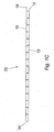
- Fig.1A is a section through a planar slab of insulating product 10.
- the product 10 has a "sandwich" construction with a core 11 of rigid phenolic insulating foam having a topside protective layer 12 and a bottomside protective layer 13, both layers 12 and 13 being in the form of an aluminium foil or fibre glass scrim layer 12, 13.
- foam slabs are, at the time of writing, available from Kingspan Insulation Limited of Herefordshire in the UK in standard sizes of 1200 mm x 2950 mm and 1000 mm x 2950 mm and are typically either 22mm or 33mm thick.
- Alternative core insulating material 11 could also be used such as a polyisocyanurate or a polyurethane.
- the planer slab 10 is formed into an intermediate insulation product 20 according to the first aspect of the present invention by firstly providing the slab 10 with a series of parallel, "V" shaped channels 14 formed therein and with the edges of slab chamfered 15, 15' at the same angle as the sides of the channels 14.
- Such channels 14 and chamfers 15, 15' may be formed in the slab 10 by a CNC router with a V shaped router bit. Where this is the case, the protective layer of material 12 may offer some protection to the core 11 against chipping or flaking during the routing, especially where the core 11 is made of a brittle insulator.
- Fig. 1B shows the intermediate insulation product 20 with optional adhesive sealant 16 deposited in the bases of the channels 14.
- the next step in forming an intermediate insulating product in accordance with the first aspect of the present invention is to apply a vapour barrier 18, having a securing means in the form of self adhesive 18A provided on its underside, to the upper and interrupted surface of the product 10 such that the adhesive 18A secures the vapour barrier 18 to the upper surface 12 of the core 11 such that the vapour barrier 18 spans across all of the channels 14.
- the vapour barrier 18 is preferably a laminated foil vapour barrier 18 and the adhesive 18A is preferably a pressure sensitive adhesive, which is pre-applied to the underside of the laminated foil barrier 18.
- Such a self-adhesive vapour barrier 18 can be commercially sourced.
- the preferred vapour barrier 18 is a five ply laminated aluminium foil vapour barrier available from Venture Tape (®) of Northants, UK sold under the trade name VentureClad 1577CW ®.
- Alternative vapour barriers could also be used such as polythene and a suitable example of such a polythene is Duponts' chlorosulfonated polyethylene products marketed as Hypalon®.
- a further outer layer is preferably attached to the bottomside on the outer surface of the aluminium foil surface 13.
- a further outer layer is also vapour proof to enable the ductwork 30 to be weather proof.
- the vapour outer layer is preferably again a laminated foil vapour barrier provided with a pre-applied pressure sensitive adhesive and such a self-adhesive vapour barrier can be commercially sourced and is more preferably a five ply laminated aluminium foil vapour barrier available from Venture Tape (®) of Northants, UK sold under the trade name VentureClad 1577CW ®.
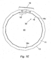
- the intermediate insulation product 20 (with optional adhesive sealant 16) may be rolled up with appropriate mechanical manipulation or by hand whereupon the continuous areas 17 of core 11 deform, enabling the channels 14 to close and a polygonal shaped insulated product 30 to be formed as shown in Fig. 1E .
- a derivative insulated product 30 is then formed which can be used as a ductwork 30 to carry fluid such as air in for example an air conditioning system for a building.
- the adhesive sealant 16 if present ensures a tight and permanent seal between the edges of the channels 14. Surplus adhesive sealant if present, egresses from the closed channels 14 and solidifies at the internal edge of the join between the channels 14.
- the section of the inner lining 18C which bridges the channels 14 will naturally be moved into the channels 14 and thereby form a seal over the channels 14.
- the width of the vapour barrier 18 typically equals the width of the intermediate insulating product 20 although as can be seen in Fig. 1C the length of the vapour barrier 18 is greater than the length of the intermediate insulating product 20 such that a flap member 18' is provided at one end of the intermediate insulating product 20.
- the entire inner throughbore 40 of the ductwork 30 can be sealed with respect to the outside of the ductwork 30 by pressing the inner lining flap 18' (as seen in Fig. 1C as being provided at one end of the vapour barrier 18) with a suitable smooth edged hand tool or machine tool to seal the flap 18' against the other end of the vapour barrier 18.
- the flap 18' (which is integral with the rest of the vapour barrier 18) provides an overlap with the other end of the vapour barrier 18 when the intermediate insulating product has been bent to form the ductwork 30 such that the vapour barrier 18 extends greater than 360 degrees around the inner throughbore.
- the ductwork 30 can be used to carry liquids and/or provides a sealed throughbore 40 such that the risk of any air born bugs/diseases finding shelter to grow is substantially reduced.
- the vapour barrier 18 can be provided with a self cleaning and/or anti-bacterial surface coating and such a surface coating is commercially available from Cytack UK Limited and/or the vapour barrier 18 can be formed of a vinyl base with such an anti-bacterial and/or self cleaning layer applied.
- the vapour barrier 18 is pressed into the channels 14 (when it is applied to the upper surface of the planer product 10 to form the intermediate product 20) by a suitable tool such as a "V" shaped smooth edged hand tool (not shown) such that in the region of 5mm of vapour barrier 18 is stuck to each channel 14.
- a suitable tool such as a "V" shaped smooth edged hand tool (not shown) such that in the region of 5mm of vapour barrier 18 is stuck to each channel 14.
- this strip 19 is the same material as the laminated foil vapour barrier 13 already applied to the underside of the core slab 10 as illustrated in figure 1A and now on the periphery of the formed polygon shaped derivative insulated product or ductwork 30 as illustrated in figure 1E .
- bands such as bands of tape or aluminium or plastic bands could be provided around the outer circumference of the derivative insulting product/ductwork 30 to provide additional strength in order to keep the edges (of the intermediate insulation product 20) together and thereby the polygon shape of the ductwork 30.
- the channels are shown in figures 1A to 1C as perfect V shaped channels. However, embodiments of the present invention are much more preferably provided with the alternative channel cross-sections illustrated in figures 2A and 2B .
- the base of a channel 14 is shown with a small, flat section 120 and in Fig. 2B , it is curved 121.
- the depth of the channels 14 could be varied depending on the strength of the insulating product core 11 and/or the thickness of the material and/or the elasticity of the bottomside protective layer 13 should it need to expand to accommodate deformation for the insulating product core 11.
- the base of the channel 14 could extend to the bottomside protective layer 13 where there would then be no deformation of the insulating core 11 as such, just flexing of the supporting bottomside protective layer 13.
- the cumulative sums of the internal angles of the channels 14 and the angle subtended between both chamfers 15, 15' is approximately 360o.
- the adhesive sealant 18 may partially fill the channel 14 such that the edges of the channel do not fully meet, a complete and structurally sound polygon 30 can be created when the cumulative sum of angles of the channels 14 and the angle subtended between both chamfers 15, 15' exceeds 360o
- the edges of the channels 14, may deform when pushed together, enabling a complete polygon 30 to be created when the cumulative sum of angles of the channels 14 and the angle subtended between both chamfers 15, 15' is less than 360o.
- the taper of the channels 14 is uniform. This need not be the case and indeed appropriate selection of tapers could be used, for example, to provide a polygon shaped derivative insulated ducting product 30 with a degree of eccentricity (e.g. approximating an ellipse).
- the resulting insulating product/ductwork 30 need not be circular but could be, for example, an oval shape having flattened sides to provide a flat oval ductwork (not shown) by leaving the upper and lower flat sections of the ductwork 30 without channels 14.
- the insulating core 11 is shown with two initial protective layers 12, 13.
- the principle of the present invention applies equally to insulator cores 11 with a single protective layer 12.
- the shape of the derivative insulated product 30 described is polygonal, the more channels 14 use to form a polygon, the more it will approximate a circle, especially if the deformation of the core 11 at the base 17 of the channel 14 smoothes the periphery of the polygon.
- the ductwork 30 would be supplied to its site of installation (e.g. a building site) from a factory pre-rolled and as shown in Fig, 1E such that it is ready to be installed on site.
- site of installation e.g. a building site
- a number of connectors are also disclosed and are shown in Figs. 3 -8 .
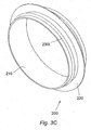
- the first variant of a connector 200 is shown in Fig, 3A, 3B and 3C .
- the connector 200 comprises an annular ring 210 having a constant inner diameter and being provided with an outwardly extending flange shoulder 220 which projects radially outwardly from the mid point of the annular ring 210.
- An outwardly and rearwardly projecting gripping means in the form of a pointed rib or barb 230L, 230R is also provided on each side of the flange ring 220 where the barb 230L, 230R has a sharpened outer point which is pointed in the direction of the flange ring 220.
- the connector 200 is preferably formed of a rigid plastic material such as a Class O (fire resistant) plastic material but it could be formed from other suitable materials and this could be a metal such as galvanised sheet, aluminium sheet, stainless steel, aluminised steel etc., depending upon the end use of the ductwork 30.
- a rigid plastic material such as a Class O (fire resistant) plastic material
- this could be a metal such as galvanised sheet, aluminium sheet, stainless steel, aluminised steel etc., depending upon the end use of the ductwork 30.
- a left hand section of ductwork 30 is pushed on to the left hand part 210L of the annular ring 210 where the outer diameter of the annular ring 210 is chosen such that it is a close fit with the inner diameter of the ductwork 30.
- the ductwork 30 is pushed on to the connector 200 until the end of the ductwork 30 butts against the left hand face of the flange should 220 and the barb 230L projects into and thereby grips the inner diameter of the ductwork 30.
- the angle of the barb 230L is such that it prevents the ductwork 30 from backing off the connector 200.
- An end of an other ductwork 30 is pushed on to the other end 210R of the connector 200 and the radius of the flange 220 is chosen such that it has the same diameter as the outer surface of both sections of ductwork 30 such that a flushed outer joint is provided between the two ends of the ductworks 30 and the flange 220.
- a suitable adhesive such as a mastic, can be applied between the connector 200 and the inner circumference of the ductwork 30 if desired, in order to increase the connection between the two.
- the two ductworks 30 can then be sealed together by applying tape around the outer circumference of the joint such that the tape seals over the joint created between the flange 220 and the two ends of the ductwork 30.
- the ductwork 30 can be cut on site to suit the length required.
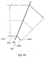
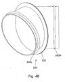
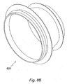
- FIG. 4A shows a connector broadly similar to the connector 200 but formed with a 45° bend between the left hand 310L and right hand 310R sides of the annular ring 310. Bards 330L and 330R are also provided and point towards the flange ring 320 and serve the same purpose as the barbs 230L, 230R and flange ring 220 as described for the connector 200. Moreover, two connectors 300 can be used with a short length of ducting 30 there between to form a 90° bend in a long length of duct tape 30.
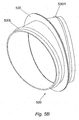
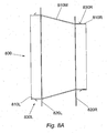
- Fig. 5A shows another type of connector which is broadly similar to the connector 300 of Fig, 4A and B where like components in the connector 500 have been indicated with a numeral prefix 5 instead of numeral pre-fix 3.
- the main difference between the connector 300 and 500 is that the connector 500 has a 30° angle between the two sides 510L and 510R and thus three connectors 500 could be used together with short lengths of ductwork 30 between them in order to make a 90° bend in a long length of a plurality of ductwork sections30 connected in series.
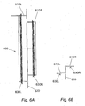
- Figs. 6A and 6B show a broadly similar connector 600 to the connector 200 of Fig, 3A to 3C where like components have been marked with the reference numeral prefix 6 instead of the reference numeral prefix 2.
- the connector 600 there is a difference in the connector 600 in that the right hand side annual ring 610 R is smaller in diameter than the left hand side annular 610R in order that the connector 600 can be used to connect two ductworks 30 having different diameters together.
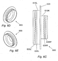
- Figs, 6C, 6D and 6E show a very similar connector 600 to that of Figs. 6A and 6B where the only difference between them is that the connector 600 in Figs. 6C and 6E has two barbs 630L and 630L' on the left hand annular ring 610L and also has two barbs 630R, 630R' on the right hand annular ring 610R in order to increase the gripping force between the connector 600 and the ductworks 30.
- the connector 800 shown in Fig, 8A is broadly similar to the connector 700 and like components have the prefix 8 instead of the prefix 7. However, the connector 800 has a circular cross section at each end 810L and 810R but which are again separated by a tapered transitional diameter section 810M.
- the connector 900 in Fig. 9 is somewhat different from the other connectors in that the left hand side 910L comprises a concave end face and is intended to be inserted into an aperture cut into the side wall of a length of circular ductwork 30 such that the end 910L provides the ability to cut into longitudinal lengths of circular ductwork 30.
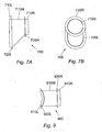
- Figs. 7A and 7B show another form of connector 700 which is broadly similar to the connector 900 shown in Fig. 9 where like components have the prefix 7 instead of the prefix 9.
- the connector 700 has a left hand annular ring 710L which has a flat end face and is oval in cross section, and the right hand side of the flange ring 720L is connected to a tapered transitional diameter section 710M which reduces in diameter from the left hand to the right hand side until it joins the left hand side of the flange ring 720R.
- the flat end face of the left hand annular ring 710L is arranged to be inserted into a like-shaped aperture cut into the planar sidewall of a rectangular section of ductwork 30.
- tape is wound around the joints created by the connectors such that the connectors are sealed with respect to the ductwork lengths 30, and a preferred tape will match the external coating of the ductwork 30.
- the tape 18 can comprise the same material as the additional layer (since it is preferably self adhesive).
- the tape 18 can comprise any other suitable tape such as reinforced Aluminium foil tape available from Kingspan Insulation Limited of Herefordshire in the UK under product number 1524.
Description
- This invention relates to a method of manufacturing non-planar derivative insulated ductwork, a derivative insulated ductwork and a section of ductwork.
- Pre-formed insulated ductwork products for carrying gasses in, for example, air conditioning systems and are used throughout the building and construction industry particularly due to their relatively fast speed of erection and relatively low cost compared to metal or plastic pipe work that must be subsequently lagged. An example of such pre-formed insulated ductwork is shown in UK Patent Publication number
GB1,137,121 US Patent Number 6,148,867 which also discloses providing longitudinal channels in a fibrous and/or cellular foam insulation material with a moisture facing outer material which can be folded into a circular cross sectioned insulated ducting. Other broadly similar systems are disclosed in International Patent Publication numberWO8504922 NL7502320 - However, such conventional systems suffer from the disadvantage that they cannot be used for ducting liquid as the liquid can ruin the insulating material. Furthermore, the open nature of the insulation material to the airflow passing through the ducting can mean that bugs/diseases etc. are more likely to be able to survive and colonise in the shelter of the insulation joints, thus causing an increased health risk. Moreover, the open nature of the insulation material can also mean that dust from the insulation material could become airborne into the air passing along the throughbore, again causing an increased health risk.
- The invention can be further described with respect to claims 1 to 20.
- In accordance with a first aspect, there is provided a method of manufacturing non-planar derivative insulated ductwork comprising an intermediate insulating product, wherein the intermediate insulating product comprises a planar insulating layer having a protective layer on the surface of the planar insulating layer, said protective layer being adapted to reduce flaking or chipping of the planar insulating layer, the method comprising the steps of forming a plurality of parallel channels into the surface of the planar insulating layer, wherein the channels comprise cross-sections with tapered sides and wherein the protective layer on the surface of the planar insulating layer is cut when the channels are formed; applying a vapour proof layer to the resulting surface of the planar insulating layer such that the vapour proof layer bridges the plurality of parallel channels; wherein the vapour proof layer comprises securing means formed on its surface and further comprises sealing means, and wherein the securing means are adapted to secure the vapour proof layer to the protective layer; bending, with subsequent mechanical manipulation, the intermediate insulating product can be bent in regions adjacent the bottom of the channels, thereby causing the channels to substantially close to form a non-planar, derivative insulated ductwork, such that the derivative insulated ductwork has an internal throughbore, and wherein the vapour proof layer forms a vapour proof inner lining to the derivative insulated ductwork; and substantially sealing the inner throughbore with respect to the outside of the derivative insulated ductwork using the sealing means of the vapour proof layer.
- Described herein is a planar intermediate insulating product which can be formed into a non-planar, derivative insulated ductwork product. The derivative insulated ductwork product is typically of sufficient strength such that it can be installed to provide a fluid conduit such as an air conditioning conduit of itself and thereby obviates the time consuming and expensive conventional requirement for metal ductwork to be applied with insulation such as that shown in
US Patent Number 6,000,437 . - Importantly, the taper enables up to the substantial entirety of the sides of the channels (as existing in the intermediate insulating product) to contact each other when formed into the derivative insulated product, thereby ensuring integrity of the insulation in the derivative insulation product.
- Typically, a continuous protective layer is provided on a resulting outermost surface of the insulating layer.
- The channels are preferably formed by routing and optionally, the channels may be at least partially filled with a sealant and/or an adhesive.
- The cumulative internal angles of the channels are typically arranged such that it is possible to bend the intermediate insulating product so as to form the derivative insulated ductwork with a complete polygon cross-section.
- Preferably, the sealing means comprises a flap member provided at one end of the vapour proof layer and which is arranged to overlap the other end of the vapour proof layer when the intermediate insulating product has been bent to form the non-planar, derivative insulated ductwork such that the vapour proof layer extends greater than 360 degrees around the internal throughbore. Moreover, the vapour proof layer is preferably substantially the same width as the resulting surface of the planar insulating layer to which it is applied, and has a longer length than the resulting surface of the planar insulating layer such that the flap member projects past one end of the planar insulating layer. Typically, the flap member is integral with and forms an extension of the rest of the vapour proof layer.
- The vapour proof layer preferably comprises a laminated vapour proof barrier and more preferably comprises a laminated foil vapour proof barrier formed from a number of layered sheets.
- Typically, the securing means comprises a self-adhesive and more preferably the self-adhesive comprises a pressure sensitive adhesive pre- applied to the resulting outermost surface of the vapour proof layer.
- Preferably, a further vapour proof layer is applied to the resulting outermost surface of the planar insulating layer such that the said further vapour proof layer forms an outer vapour proof protective barrier to the derivative insulated ductwork. Preferably, a further securing means is provided between the further vapour proof layer and the outermost surface, and the said further securing means preferably comprises an adhesive means initially provided on the inner most surface of the further vapour proof layer.
- The planar insulating layer comprises a substantially rigid material, and more preferably comprises a rigid phenolic foam.
- According to a second aspect there is also provided a derivative insulated ductwork product formed from an intermediate insulating product according to the first aspect described herein.
- Typically, a complete polygon cross-section is formed from an intermediate insulating product with cumulative internal angles of the channels such that it was possible to bend the intermediate insulating product so as to form a complete polygonal cross-section.
- Preferably, the derivative insulated ductwork product is secured along a joining edge by a strip of adhesive tape applied along the joining edges of what was the intermediate insulation product.
- Further described herein is an exemplary section of ductwork product formed from an intermediate insulating product according to the first aspect described herein by mechanical manipulation of the intermediate insulating product thereof to bend it in regions adjacent the bottom of the channels, thereby causing the channels to close to form the non-planar, derivative insulated ductwork product.
- Further described herein is an exemplary connecting means for connecting a first section of ductwork in accordance with the third aspect described above, to a second section of ductwork in accordance with the third aspect described above, the connecting means comprising:- a first fitting member having an open end for accepting an end of the first section of ductwork; wherein the other end of the first fitting member is connected to a side of a flange member which projects outwardly from the first fitting member; and a second fitting member having an open end for accepting an end of the second section of ductwork; wherein the other end of the second fitting member is connected to a side of a flange member which projects outwardly from the second fitting member; and an internal throughbore which provides a sealed passageway for fluid to travel from a throughbore of the first ductwork, through said internal throughbore and into a throughbore of the second ductwork.
- Further described herein is an exemplary ductwork system comprising two or more sections of ductwork in accordance with the third aspect described above and one or more connecting devices, the connecting devices comprising:- a first fitting member having an open end for accepting an end of the first section of ductwork; wherein the other end of the first fitting member is connected to a side of a first flange member which projects outwardly from the first fitting member; and a second fitting member having an open end for accepting an end of the second section of ductwork; wherein the other end of the second fitting member is connected to a side of a second flange member which projects outwardly from the second fitting member; and an internal throughbore which provides a sealed passageway for fluid to travel from a throughbore of the first ductwork, through said internal throughbore and into a throughbore of the second ductwork.
- Preferably, the first and second fitting members comprise respective first and second annular rings.
- Typically, the first and second annular rings each comprise a substantially constant inner diameter and a substantially constant outer diameter.
- Preferably, the said flange member(s) project radially outwardly from the respective first and second fitting members.
- The outer diameter of the respective first and second fitting member preferably contacts the inner diameter of the respective ductwork and the said one face of the flange member is arranged into butting contact with the end of the respective ductwork.
- The first and second fitting members preferably further comprise a securing means which acts between the fitting members and the respective ductwork to prevent separation of the ductwork from the fitting member in a direction away from the flange member.
- The securing means preferably comprise one or more barb member(s) which point in a direction toward the respective flange member.
- The first and second fitting members may each comprise the same outer diameter. Alternatively, the first and second fitting members may each comprise different outer diameters.
- Preferably, the flange member projects outwardly from the first and second fitting member by a distance substantially equal to the sidewall thickness of the ducting.
-
-
Figs. 1A to 1F are sections illustrating the formation of a derivate insulated product from an intermediate insulation product. -
Figs. 2A and 2B are sections illustrating alternative channel cross-sections of an intermediate insulation product in accordance with the first, second and third aspects of the present invention; andFig. 3A is a side view of a connector where both ductworks have the same internal diameter; -
Fig. 3B is a cross sectional side view through one half of the connector ofFig. 3A ; -
Fig. 3C is a perspective view of the connector atFig. 3A ; -
Fig. 4A is a side view of another embodiment of a connector for connecting two ductworks having the same internal diameter together but at a 45° angle to one another in order to create a 45° bend; -
Fig. 4B is a perspective view of the connector atFig. 4A ; -
Fig. 5A is a side view of another embodiment of a connector for connecting two ductworks having the same internal diameter together but at a 30° angle to one another in order to create a 30°bend; -
Fig. 5B is a perspective view of the connector atFig. 5A ; -
Fig. 6A is a side view of a connector for connecting one ductwork having a larger internal diameter to another ductwork having a smaller internal diameter; -
Fig. 6B is a cross sectional view through the lower half of the connector atFig. 6A ; -
Fig. 6C is a side view of a slightly different embodiment of the connector shown inFig. 6A ; -
Fig. 6D is a first perspective side view of the connector shown inFig. 6C ; -
Fig. 6E is another perspective side view of the connector shown inFig. 6C ; -
Fig. 7A is a side view of a connector in accordance with the fourth aspect of the present invention to break into a square section of ductwork to provide a branch of another section of ductwork;Fig. 7B is an end view of the connector shown inFig. 7A ; -
Fig. 8A is another embodiment of a connector in accordance with a fourth aspect of the present invention for connecting a relatively large circular ductwork to a relatively small diameter circular ductwork; -
Fig. 8B is a perspective view of the connector shown inFig. 8A ; and -
Fig. 9 is a side view of a connector in accordance with the fourth aspect of the present invention to break into a circular section of ductwork to provide a branch of another section of ductwork. -
Fig.1A is a section through a planar slab of insulatingproduct 10. Theproduct 10 has a "sandwich" construction with acore 11 of rigid phenolic insulating foam having a topsideprotective layer 12 and a bottomsideprotective layer 13, bothlayers glass scrim layer product 10 may be commercially sourced, for example, such foam slabs are, at the time of writing, available from Kingspan Insulation Limited of Herefordshire in the UK in standard sizes of 1200 mm x 2950 mm and 1000 mm x 2950 mm and are typically either 22mm or 33mm thick. Alternativecore insulating material 11 could also be used such as a polyisocyanurate or a polyurethane. - Referring to
Fig. 1B , theplaner slab 10 is formed into anintermediate insulation product 20 according to the first aspect of the present invention by firstly providing theslab 10 with a series of parallel, "V" shapedchannels 14 formed therein and with the edges of slab chamfered 15, 15' at the same angle as the sides of thechannels 14. -
Such channels 14 andchamfers slab 10 by a CNC router with a V shaped router bit. Where this is the case, the protective layer ofmaterial 12 may offer some protection to the core 11 against chipping or flaking during the routing, especially where thecore 11 is made of a brittle insulator. - The cumulative sums of the internal angles of the all channels and the angle subtended between both
chamfers Fig. 1B shows theintermediate insulation product 20 with optionaladhesive sealant 16 deposited in the bases of thechannels 14. - The next step in forming an intermediate insulating product in accordance with the first aspect of the present invention is to apply a
vapour barrier 18, having a securing means in the form of self adhesive 18A provided on its underside, to the upper and interrupted surface of theproduct 10 such that the adhesive 18A secures thevapour barrier 18 to theupper surface 12 of the core 11 such that thevapour barrier 18 spans across all of thechannels 14. Thevapour barrier 18 is preferably a laminatedfoil vapour barrier 18 and the adhesive 18A is preferably a pressure sensitive adhesive, which is pre-applied to the underside of thelaminated foil barrier 18. Such a self-adhesive vapour barrier 18 can be commercially sourced. For example, thepreferred vapour barrier 18 is a five ply laminated aluminium foil vapour barrier available from Venture Tape (®) of Northants, UK sold under the trade name VentureClad 1577CW ®. Alternative vapour barriers could also be used such as polythene and a suitable example of such a polythene is Duponts' chlorosulfonated polyethylene products marketed as Hypalon®. - Optionally, where the
ductwork 30 is to be used in external applications (e.g. on the outside of buildings, factories, oil rigs etc.), a further outer layer (not shown) is preferably attached to the bottomside on the outer surface of thealuminium foil surface 13. Preferably, such a further outer layer is also vapour proof to enable theductwork 30 to be weather proof. The vapour outer layer is preferably again a laminated foil vapour barrier provided with a pre-applied pressure sensitive adhesive and such a self-adhesive vapour barrier can be commercially sourced and is more preferably a five ply laminated aluminium foil vapour barrier available from Venture Tape (®) of Northants, UK sold under the trade name VentureClad 1577CW ®. - This results in the formation of the intermediate insulating
product 20. - Thereafter and as illustrated in
Figs. 1D ,1E and 1F , the intermediate insulation product 20 (with optional adhesive sealant 16) may be rolled up with appropriate mechanical manipulation or by hand whereupon thecontinuous areas 17 ofcore 11 deform, enabling thechannels 14 to close and a polygonal shapedinsulated product 30 to be formed as shown inFig. 1E . Thus, a derivativeinsulated product 30 is then formed which can be used as aductwork 30 to carry fluid such as air in for example an air conditioning system for a building. - The
adhesive sealant 16 if present ensures a tight and permanent seal between the edges of thechannels 14. Surplus adhesive sealant if present, egresses from theclosed channels 14 and solidifies at the internal edge of the join between thechannels 14. - Moreover, and as can be best seen in
Fig. 1F , when the intermediate insulatingproduct 20 withvapour barrier 18 attached is rolled up, the section of the inner lining 18C which bridges thechannels 14 will naturally be moved into thechannels 14 and thereby form a seal over thechannels 14. The width of thevapour barrier 18 typically equals the width of the intermediate insulatingproduct 20 although as can be seen inFig. 1C the length of thevapour barrier 18 is greater than the length of the intermediate insulatingproduct 20 such that a flap member 18' is provided at one end of the intermediate insulatingproduct 20. Furthermore, when the intermediate insulatingproduct 20 has been fully rolled up to form theductwork 30, the entireinner throughbore 40 of theductwork 30 can be sealed with respect to the outside of theductwork 30 by pressing the inner lining flap 18' (as seen inFig. 1C as being provided at one end of the vapour barrier 18) with a suitable smooth edged hand tool or machine tool to seal the flap 18' against the other end of thevapour barrier 18. Accordingly, the flap 18' (which is integral with the rest of the vapour barrier 18) provides an overlap with the other end of thevapour barrier 18 when the intermediate insulating product has been bent to form theductwork 30 such that thevapour barrier 18 extends greater than 360 degrees around the inner throughbore. - Consequently, the
ductwork 30 can be used to carry liquids and/or provides a sealedthroughbore 40 such that the risk of any air born bugs/diseases finding shelter to grow is substantially reduced. - Alternatively, and/or additionally, the
vapour barrier 18 can be provided with a self cleaning and/or anti-bacterial surface coating and such a surface coating is commercially available from Cytack UK Limited and/or thevapour barrier 18 can be formed of a vinyl base with such an anti-bacterial and/or self cleaning layer applied. - The
vapour barrier 18 is pressed into the channels 14 (when it is applied to the upper surface of theplaner product 10 to form the intermediate product 20) by a suitable tool such as a "V" shaped smooth edged hand tool (not shown) such that in the region of 5mm ofvapour barrier 18 is stuck to eachchannel 14. - The longitudinal edges of the
intermediate insulation product 20 which have been pushed together are held in place by anadhesive strip 19 of laminated foil vapour barrier. Ideally, thisstrip 19 is the same material as the laminatedfoil vapour barrier 13 already applied to the underside of thecore slab 10 as illustrated infigure 1A and now on the periphery of the formed polygon shaped derivative insulated product orductwork 30 as illustrated infigure 1E . - Optionally and additionally bands such as bands of tape or aluminium or plastic bands could be provided around the outer circumference of the derivative insulting product/
ductwork 30 to provide additional strength in order to keep the edges (of the intermediate insulation product 20) together and thereby the polygon shape of theductwork 30.. - The channels are shown in
figures 1A to 1C as perfect V shaped channels. However, embodiments of the present invention are much more preferably provided with the alternative channel cross-sections illustrated infigures 2A and 2B . InFig. 2A , the base of achannel 14 is shown with a small,flat section 120 and inFig. 2B , it is curved 121. Also, the depth of thechannels 14 could be varied depending on the strength of the insulatingproduct core 11 and/or the thickness of the material and/or the elasticity of the bottomsideprotective layer 13 should it need to expand to accommodate deformation for the insulatingproduct core 11. Conceivably, the base of thechannel 14 could extend to the bottomsideprotective layer 13 where there would then be no deformation of the insulatingcore 11 as such, just flexing of the supporting bottomsideprotective layer 13. - In the above example, it is stated that the cumulative sums of the internal angles of the
channels 14 and the angle subtended between bothchamfers adhesive sealant 18 may partially fill thechannel 14 such that the edges of the channel do not fully meet, a complete and structurallysound polygon 30 can be created when the cumulative sum of angles of thechannels 14 and the angle subtended between bothchamfers channels 14, may deform when pushed together, enabling acomplete polygon 30 to be created when the cumulative sum of angles of thechannels 14 and the angle subtended between bothchamfers - In the above example, the taper of the
channels 14 is uniform. This need not be the case and indeed appropriate selection of tapers could be used, for example, to provide a polygon shaped derivativeinsulated ducting product 30 with a degree of eccentricity (e.g. approximating an ellipse). For example, the resulting insulating product/ductwork 30 need not be circular but could be, for example, an oval shape having flattened sides to provide a flat oval ductwork (not shown) by leaving the upper and lower flat sections of theductwork 30 withoutchannels 14. - Also in the above example, the insulating
core 11 is shown with two initialprotective layers insulator cores 11 with a singleprotective layer 12. - Furthermore, whilst the shape of the derivative
insulated product 30 described is polygonal, themore channels 14 use to form a polygon, the more it will approximate a circle, especially if the deformation of the core 11 at thebase 17 of thechannel 14 smoothes the periphery of the polygon. - Typically, the
ductwork 30 would be supplied to its site of installation (e.g. a building site) from a factory pre-rolled and as shown inFig, 1E such that it is ready to be installed on site. In order to aid installation on site and also to ensure thatindividual ductwork 30 sections can be joined together in a sealed manner, a number of connectors are also disclosed and are shown inFigs. 3 -8 . - The first variant of a
connector 200 is shown inFig, 3A, 3B and3C . Theconnector 200 comprises anannular ring 210 having a constant inner diameter and being provided with an outwardly extendingflange shoulder 220 which projects radially outwardly from the mid point of theannular ring 210. An outwardly and rearwardly projecting gripping means in the form of a pointed rib orbarb flange ring 220 where thebarb flange ring 220. Theconnector 200 is preferably formed of a rigid plastic material such as a Class O (fire resistant) plastic material but it could be formed from other suitable materials and this could be a metal such as galvanised sheet, aluminium sheet, stainless steel, aluminised steel etc., depending upon the end use of theductwork 30. - In use, a left hand section of
ductwork 30 is pushed on to theleft hand part 210L of theannular ring 210 where the outer diameter of theannular ring 210 is chosen such that it is a close fit with the inner diameter of theductwork 30. Theductwork 30 is pushed on to theconnector 200 until the end of theductwork 30 butts against the left hand face of the flange should 220 and thebarb 230L projects into and thereby grips the inner diameter of theductwork 30. The angle of thebarb 230L is such that it prevents theductwork 30 from backing off theconnector 200. An end of another ductwork 30 is pushed on to theother end 210R of theconnector 200 and the radius of theflange 220 is chosen such that it has the same diameter as the outer surface of both sections ofductwork 30 such that a flushed outer joint is provided between the two ends of theductworks 30 and theflange 220. A suitable adhesive, such as a mastic, can be applied between theconnector 200 and the inner circumference of theductwork 30 if desired, in order to increase the connection between the two. The twoductworks 30 can then be sealed together by applying tape around the outer circumference of the joint such that the tape seals over the joint created between theflange 220 and the two ends of theductwork 30. - The
ductwork 30 can be cut on site to suit the length required. - Various other connectors are shown in the drawings.
Fig. 4A shows a connector broadly similar to theconnector 200 but formed with a 45° bend between theleft hand 310L andright hand 310R sides of the annular ring 310.Bards flange ring 320 and serve the same purpose as thebarbs flange ring 220 as described for theconnector 200. Moreover, twoconnectors 300 can be used with a short length ofducting 30 there between to form a 90° bend in a long length ofduct tape 30. -
Fig. 5A shows another type of connector which is broadly similar to theconnector 300 ofFig, 4A and B where like components in theconnector 500 have been indicated with a numeral prefix 5 instead of numeral pre-fix 3. The main difference between theconnector connector 500 has a 30° angle between the twosides connectors 500 could be used together with short lengths ofductwork 30 between them in order to make a 90° bend in a long length of a plurality of ductwork sections30 connected in series. -
Figs. 6A and 6B show a broadlysimilar connector 600 to theconnector 200 ofFig, 3A to 3C where like components have been marked with the reference numeral prefix 6 instead of the reference numeral prefix 2. - However, there is a difference in the
connector 600 in that the right hand sideannual ring 610 R is smaller in diameter than the left hand side annular 610R in order that theconnector 600 can be used to connect twoductworks 30 having different diameters together. -
Figs, 6C, 6D and 6E show a verysimilar connector 600 to that ofFigs. 6A and 6B where the only difference between them is that theconnector 600 inFigs. 6C and 6E has twobarbs annular ring 610L and also has twobarbs annular ring 610R in order to increase the gripping force between theconnector 600 and theductworks 30. - The
connector 800 shown inFig, 8A is broadly similar to theconnector 700 and like components have the prefix 8 instead of the prefix 7. However, theconnector 800 has a circular cross section at eachend transitional diameter section 810M. - The
connector 900 inFig. 9 is somewhat different from the other connectors in that theleft hand side 910L comprises a concave end face and is intended to be inserted into an aperture cut into the side wall of a length ofcircular ductwork 30 such that theend 910L provides the ability to cut into longitudinal lengths ofcircular ductwork 30.Figs. 7A and 7B show another form ofconnector 700 which is broadly similar to theconnector 900 shown inFig. 9 where like components have the prefix 7 instead of the prefix 9. However, theconnector 700 has a left handannular ring 710L which has a flat end face and is oval in cross section, and the right hand side of theflange ring 720L is connected to a taperedtransitional diameter section 710M which reduces in diameter from the left hand to the right hand side until it joins the left hand side of theflange ring 720R. The flat end face of the left handannular ring 710L is arranged to be inserted into a like-shaped aperture cut into the planar sidewall of a rectangular section ofductwork 30. - In all cases, tape is wound around the joints created by the connectors such that the connectors are sealed with respect to the
ductwork lengths 30, and a preferred tape will match the external coating of theductwork 30. For example, if theductwork 30 is supplied with the additional vapour proof outer layer, thetape 18 can comprise the same material as the additional layer (since it is preferably self adhesive). However, if theductwork 30 is supplied without the additional vapour proof outer layer, thetape 18 can comprise any other suitable tape such as reinforced Aluminium foil tape available from Kingspan Insulation Limited of Herefordshire in the UK under product number 1524. - Modifications and improvements to the embodiments of the present inventions described herein may be made by those persons skilled in the relevant art without departing from the scope of the invention, as defined by the appending claims.
Claims (20)
- A method of manufacturing non-planar derivative insulated ductwork (30) comprising an intermediate insulating product (20), wherein the intermediate insulating product (20) comprises a planar insulating layer (11) having a protective layer on the surface of the planar insulating layer, said protective layer being adapted to reduce flaking or chipping of the planar insulating layer, the method comprising the steps of:forming a plurality of parallel channels (14) into the surface of the planar insulating layer (11), wherein the channels (14) comprise cross-sections with tapered sides and wherein the protective layer is provided on the surface of the planar insulating layer prior to forming the channels;applying a vapour proof layer (18) to the resulting surface of the planar insulating layer and pressing the vapour proof layer into the channels by a suitable tool such that the vapour proof layer (18) bridges the plurality of parallel channels (14),wherein the vapour proof layer comprises securing means formed on its surface and further comprises sealing means, and wherein the securing means are adapted to secure the vapour proof layer (18) to the protective layer;bending, with subsequent mechanical manipulation, the intermediate insulating product (20) in regions adjacent the bottom of the channels (14), thereby causing the channels (14) to substantially close to form the non-planar, derivative insulated ductwork, such that the derivative insulated ductwork (30) has an internal throughbore, wherein the vapour proof layer (18) forms a vapour proof inner lining (18C) to the derivative insulated ductwork; andsubstantially sealing the internal throughbore with respect to the outside of the derivative insulated ductwork using the sealing means of the vapour proof layer (18).
- The method as claimed in claim 1, further comprising providing a continuous protective layer on a resulting outermost surface of the insulating layer.
- The method as claimed in claim 1 or claim 2, wherein the channels (14) are formed by routing.
- The method according to any preceding claim, wherein the channels (14) are at least partially filled with a sealant and/or an adhesive.
- The method according to any preceding claim, wherein the cumulative internal angles of the channels (14) are such that it is possible to bend the intermediate insulating product (20) so as to form the derivative insulated ductwork with a complete polygon cross-section.
- The method according to any preceding claim, wherein the planar insulating layer (11) comprises a substantially rigid material.
- The method according to claim 6, wherein the substantially rigid material comprises rigid phenolic foam.
- The method according to any preceding claim, wherein the sealing means comprises a flap member (18') provided at one end of the vapour proof layer (18) and which is arranged to overlap the other end of the vapour proof layer (18) when the intermediate insulating product (20) has been bent to form the non-planar, derivative insulated ductwork (30) such that the vapour proof layer (18) extends greater than 360 degrees around the internal throughbore.
- The method according to claim 8, wherein the flap member (18') is integral with and forms an extension of the rest of the vapour proof layer (18).
- The method according to any preceding claim, wherein the vapour proof layer (18) is substantially the same width as the resulting surface of the planar insulating layer (11) to which it is applied, and has a longer length than the resulting surface of the planar insulating layer (11) such that the flap member (18') projects past one end of the planar insulating layer (11).
- The method according to any preceding claim, wherein the vapour proof layer (18) comprises a laminated vapour proof barrier.
- The method according to claim 11, wherein the vapour proof barrier comprises a laminated foil vapour proof barrier formed from a number of layered sheets.
- The method according to any preceding claim, wherein the securing means comprises a self adhesive.
- The method according to claim 13, wherein the self-adhesive comprises a pressure sensitive adhesive pre-applied to the resulting outermost surface of the vapour proof layer (18).
- The method according to any preceding claim, further comprising the step of applying a further vapour proof layer (18) to the resulting outermost surface of the planar insulating layer (11) such that the said further vapour proof layer (18) forms an outer vapour proof protective barrier to the derivative insulated ductwork.
- The method according to claim 15, wherein a further securing means is provided between the further vapour proof layer (18) and the said outermost surface.
- The method according to claim 16, wherein the said further securing means comprises an adhesive means initially provided on the innermost surface of the further vapour proof layer (18).
- A non-planar derivative insulated ductwork (30) comprising an intermediate insulating product (20) formed by the method according to any of claims 1 to 17.
- A derivative insulated ductwork (30) as claimed in claim 18 with a complete polygon cross-section having been formed from an intermediate insulating product (20) with cumulative internal angles of the channels (14) such that it was possible to bend the intermediate insulating product (20) so as to form a complete polygonal cross-section.
- A derivative insulated ductwork (30) as claimed in claims 18 or 19 and secured along a joining edge by a strip of adhesive tape applied along the joining edges of what was the intermediate insulation product.
Priority Applications (7)
| Application Number | Priority Date | Filing Date | Title |
|---|---|---|---|
| PL07823953T PL2079954T3 (en) | 2006-09-29 | 2007-09-28 | Insulated ductwork products |
| DK11187763.5T DK2416044T3 (en) | 2006-09-29 | 2007-09-28 | Isolated duct system products |
| PL11187763T PL2416044T3 (en) | 2006-09-29 | 2007-09-28 | Insulated ductwork products |
| SI200731664T SI2079954T1 (en) | 2006-09-29 | 2007-09-28 | Insulated ductwork products |
| EP11187763.5A EP2416044B1 (en) | 2006-09-29 | 2007-09-28 | Insulated ductwork products |
| CY20151100548T CY1116749T1 (en) | 2006-09-29 | 2015-06-26 | NETWORK PIPELINE INSULATION |
| CY181101026T CY1120956T1 (en) | 2006-09-29 | 2018-10-05 | PIPELINE SYSTEM INSULATION PRODUCTS |
Applications Claiming Priority (3)
| Application Number | Priority Date | Filing Date | Title |
|---|---|---|---|
| GB0619178A GB2442240A (en) | 2006-09-29 | 2006-09-29 | Insulating products |
| GB0711224A GB2442292B (en) | 2006-09-29 | 2007-06-11 | Insulating ductwork products |
| PCT/GB2007/003692 WO2008038013A2 (en) | 2006-09-29 | 2007-09-28 | Insulated ductwork products |
Related Child Applications (2)
| Application Number | Title | Priority Date | Filing Date |
|---|---|---|---|
| EP11187763.5A Division-Into EP2416044B1 (en) | 2006-09-29 | 2007-09-28 | Insulated ductwork products |
| EP11187763.5A Division EP2416044B1 (en) | 2006-09-29 | 2007-09-28 | Insulated ductwork products |
Publications (2)
| Publication Number | Publication Date |
|---|---|
| EP2079954A2 EP2079954A2 (en) | 2009-07-22 |
| EP2079954B1 true EP2079954B1 (en) | 2015-04-15 |
Family
ID=37434869
Family Applications (2)
| Application Number | Title | Priority Date | Filing Date |
|---|---|---|---|
| EP11187763.5A Active EP2416044B1 (en) | 2006-09-29 | 2007-09-28 | Insulated ductwork products |
| EP07823953.0A Active EP2079954B1 (en) | 2006-09-29 | 2007-09-28 | Insulated ductwork products |
Family Applications Before (1)
| Application Number | Title | Priority Date | Filing Date |
|---|---|---|---|
| EP11187763.5A Active EP2416044B1 (en) | 2006-09-29 | 2007-09-28 | Insulated ductwork products |
Country Status (18)
| Country | Link |
|---|---|
| US (1) | US8950439B2 (en) |
| EP (2) | EP2416044B1 (en) |
| JP (3) | JP2010505083A (en) |
| CN (1) | CN101517296B (en) |
| AU (1) | AU2007301752B2 (en) |
| CA (1) | CA2664046C (en) |
| CY (2) | CY1116749T1 (en) |
| DK (2) | DK2079954T3 (en) |
| EA (1) | EA018837B1 (en) |
| ES (2) | ES2540913T3 (en) |
| GB (4) | GB2442240A (en) |
| HU (2) | HUE040040T2 (en) |
| IL (1) | IL197880A0 (en) |
| LT (1) | LT2416044T (en) |
| PL (2) | PL2079954T3 (en) |
| PT (2) | PT2416044T (en) |
| SI (2) | SI2416044T1 (en) |
| WO (1) | WO2008038013A2 (en) |
Families Citing this family (19)
| Publication number | Priority date | Publication date | Assignee | Title |
|---|---|---|---|---|
| DE102005007201B4 (en) | 2005-02-16 | 2017-03-30 | IMES Grundstücksverwaltung-GmbH | Cover with divided chambers, which can be moved apart on their neighboring walls |
| GB2442240A (en) | 2006-09-29 | 2008-04-02 | Specialist Insulation Ltd | Insulating products |
| GB0906312D0 (en) * | 2009-04-09 | 2009-05-20 | Zircotec Ltd | An article, an intermediate product and a method of making an article |
| FI125279B (en) * | 2011-12-16 | 2015-08-14 | Paroc Group Oy | Pipe insulation |
| US20130291984A1 (en) * | 2012-05-03 | 2013-11-07 | Armacell Enterprise Gmbh | Insulation Assemblies, Insulated Conduit Assemblies, and Related Methods |
| US9291290B2 (en) * | 2012-05-21 | 2016-03-22 | Havaco Technologies | Foldable HVAC conduit and duct collar |
| US8667995B1 (en) | 2012-05-23 | 2014-03-11 | Carl Fanelli | Insulated ducts and insulated ductworks |
| CA2942808C (en) * | 2013-03-15 | 2023-06-13 | Fran Lanciaux | Clad duct and method for producing a clad duct |
| MX2016014453A (en) * | 2014-05-07 | 2017-04-06 | Ronald Dalgarno Michael | Ducting systems. |
| ES2559152B1 (en) * | 2015-11-19 | 2016-10-17 | Protectores Deportivos 2014, S.L. | Security fence guard and manufacturing procedure |
| SI3244118T1 (en) * | 2016-05-10 | 2019-09-30 | Kaimann Gmbh | Shaped article for a non-sag flexible insulation |
| US10689846B2 (en) * | 2016-09-09 | 2020-06-23 | United States Gypsum Company | Shaftwall system using folded panels, and panel |
| US10976070B1 (en) | 2017-03-31 | 2021-04-13 | Albers Mechanical Contractors, Inc. | Foam core duct system protected by metal sleeves with integral flanges |
| JP2020532698A (en) * | 2017-09-05 | 2020-11-12 | オウェンス コーニング インテレクチュアル キャピタル リミテッド ライアビリティ カンパニー | Insulation for pipes |
| US11492019B2 (en) * | 2018-01-31 | 2022-11-08 | Tata Steel Nederland Technology B.V. | Tube segment and tube for evacuated tube transport system |
| US10782046B2 (en) * | 2018-06-20 | 2020-09-22 | Johns Manville | Methods, materials, and equipment to form improved fit duct liner insulation for round and oval HVAC duct systems |
| US10774976B2 (en) * | 2018-09-12 | 2020-09-15 | Johns Manville | Systems and methods for insulating a pipe with a pre-applied vapor-barrier stop |
| WO2022174888A1 (en) * | 2021-02-16 | 2022-08-25 | Dalgarno Ip Ltd | A duct section for a duct distribution system and a method of making a duct section |
| KR20230099395A (en) * | 2021-12-27 | 2023-07-04 | 한국광기술원 | the improved pipe structure with reinforcement rib and manufacturing method thereof |
Citations (1)
| Publication number | Priority date | Publication date | Assignee | Title |
|---|---|---|---|---|
| NL7502320A (en) * | 1974-03-01 | 1975-09-03 | Strulik Wilhelm P | TUBE WITH A HEAT AND SOUND INSULATION FOR REPLACEMENT AIR AND AIR REGULATED IN TEMPERATURE AND HUMIDITY. |
Family Cites Families (66)
| Publication number | Priority date | Publication date | Assignee | Title |
|---|---|---|---|---|
| GB113121A (en) | 1917-01-17 | 1918-01-17 | Thomas Henry Cleathero | Improvements relating to Apparatus for Spraying and for similar purposes. |
| CH228042A (en) * | 1942-09-28 | 1943-07-31 | Ab Mo Och Domsjo Treetex | Plate for forming insulating layers on structures with curved surfaces, in particular pipelines. |
| US2776231A (en) * | 1954-06-28 | 1957-01-01 | Armstrong Cork Co | Segmented insulating covering for pipes and the like |
| US3117902A (en) * | 1958-10-20 | 1964-01-14 | Fastab Insulations Inc | Insulating coverings for enclosures |
| GB949329A (en) * | 1961-05-01 | 1964-02-12 | Bell S Asbestos And Engineerin | Improvements in or relating to the thermal insulation for pipes |
| US3251382A (en) * | 1963-06-24 | 1966-05-17 | Tatsch Richard | Foldable conduit structure |
| US3336951A (en) * | 1964-04-27 | 1967-08-22 | Eagle Picher Co | Grooved insulating material |
| GB1137121A (en) * | 1964-10-21 | 1968-12-18 | Lo Dense Fixings Rugby Ltd | Improvements in and in the manufacture of insulated ducting, tubing or casing |
| US3463691A (en) * | 1965-08-11 | 1969-08-26 | American Standard Inc | Method for forming liquid heat exchange piping system |
| US3557840A (en) * | 1968-05-09 | 1971-01-26 | Atlas Chem Ind | Cellular plastic foam insulation board structures |
| GB1257799A (en) * | 1968-09-04 | 1971-12-22 | ||
| US3687170A (en) * | 1970-10-26 | 1972-08-29 | Ind Insulations Inc | Heat insulating assembly |
| US3955834A (en) * | 1972-02-11 | 1976-05-11 | Aktiebolaget Svenska Flaktfabriken | Apparatus for connecting ducts with a self-sealing joint |
| JPS4941652U (en) * | 1972-07-18 | 1974-04-12 | ||
| GB1414113A (en) | 1974-01-19 | 1975-11-19 | Johns Manville | Air duct and method of making same |
| FR2409855A1 (en) * | 1977-11-24 | 1979-06-22 | Chollet Jacques | Prefabricated refractory elements for lagging or sleeves - which can easily be bent to fit round objects for protection against fire |
| GB2042118A (en) * | 1979-02-13 | 1980-09-17 | Weir Polypac Ltd | Pipe coupling |
| DE3121602A1 (en) * | 1981-05-30 | 1982-12-23 | Erwaeta Bohrtechnik GmbH, 2300 Kiel | Sleeve connection for the ends of in each case two lengths of pipe |
| FI66478C (en) * | 1981-07-06 | 1984-10-10 | Partek Ab | ROERSKAOLELEMENT OCH SAETT ATT FRAMSTAELLA DETSAMMA |
| DE3232277A1 (en) * | 1982-08-31 | 1984-03-01 | Bernd 4902 Bad Salzuflen Friemuth | Pipe insulating element |
| FR2562837B1 (en) * | 1984-04-16 | 1987-06-26 | Mcintosh Jonathan | COMPOSITE CONSTRUCTION ELEMENTS AND METHOD FOR THE PRODUCTION OF MULTI-DIRECTIONAL STRUCTURES BY FORMING AND / OR ASSEMBLY OF SUCH ELEMENTS |
| JPS61143484A (en) | 1984-12-17 | 1986-07-01 | Toyoda Gosei Co Ltd | Sealant for air duct |
| DE3515737A1 (en) | 1985-05-02 | 1986-11-06 | Karl Meinig KG, 7201 Rietheim-Weilheim | FLANGE RING FOR PIPES |
| DE3540712A1 (en) | 1985-11-16 | 1987-05-21 | Hans Zeidler | Heating duct |
| JPS62117458A (en) | 1985-11-18 | 1987-05-28 | Fuji Photo Film Co Ltd | Image pickup system for photograph |
| JPS62117458U (en) * | 1986-01-14 | 1987-07-25 | ||
| US4842908A (en) * | 1987-09-15 | 1989-06-27 | Venture Tape Corp. | Insulation with tape adhering surface |
| JPH0448429Y2 (en) * | 1987-11-13 | 1992-11-16 | ||
| JPH03187384A (en) | 1989-12-15 | 1991-08-15 | Kirin Brewery Co Ltd | Continuous fermentation process and reactor therefor |
| FR2657944B1 (en) * | 1990-02-05 | 1992-09-04 | Texas Ind Insulations | COMPOSITE PLATE INSULATION MATERIAL WITH V-NOTCHES |
| US5219403A (en) * | 1990-02-14 | 1993-06-15 | Gerard C. Murphy | Plastic self-insulating ductwork system |
| JPH0448429A (en) | 1990-06-13 | 1992-02-18 | Matsushita Electric Ind Co Ltd | Digital magnetic recording and reproducing method |
| DE9015484U1 (en) * | 1990-11-12 | 1991-01-31 | Thyssen Polymer Gmbh, 8000 Muenchen, De | |
| JPH05203246A (en) | 1991-09-12 | 1993-08-10 | Glass Master Corp | Cutting and processing device and method of circular duct from duct board and circular air duct manufactured by it |
| JPH05118484A (en) * | 1991-10-28 | 1993-05-14 | Sekisui Chem Co Ltd | Slip joint for duct |
| JPH0738895A (en) | 1993-07-17 | 1995-02-07 | G C Technol Kk | Image encoding device |
| JPH0738895U (en) * | 1993-12-16 | 1995-07-14 | 日東紡績株式会社 | Inorganic fiber insulation tube |
| JPH07293763A (en) | 1994-04-21 | 1995-11-10 | Calsonic Corp | Pipe body connecting structure |
| US5567504A (en) * | 1994-05-31 | 1996-10-22 | Schuller International, Inc. | Glass fiber duct board with coated grooves and the method of making the same |
| CN2211532Y (en) * | 1995-01-20 | 1995-11-01 | 潘锦云 | Polyethylene thermal insulating pipe |
| DK0820568T3 (en) * | 1995-04-13 | 2000-08-28 | Huntsman Ici Chem Llc | Process for the manufacture of non-planar, air-empty insulating plates |
| JPH08326991A (en) | 1995-05-30 | 1996-12-10 | Toray Dow Corning Silicone Co Ltd | Heat shielding cover of heating element and its manufacture |
| US5953818A (en) * | 1995-09-14 | 1999-09-21 | Johns Manville International, Inc. | Method of kerfing insulation boards and duct liners and the like formed from said boards |
| US5918644A (en) * | 1996-05-23 | 1999-07-06 | Haack; C. William | Air duct and method of making same |
| JPH11182784A (en) * | 1997-12-22 | 1999-07-06 | Nichias Corp | Heat insulating material and manufacture therefor |
| US6000437A (en) * | 1998-01-16 | 1999-12-14 | Certain Teed Corporation | Coated liner for curved ducts |
| DE59900006D1 (en) | 1998-02-19 | 2000-09-07 | Wacker Chemie Gmbh | Method for isolating curved surfaces |
| JPH11270781A (en) | 1998-03-20 | 1999-10-05 | Sekisui Chem Co Ltd | Heat insulating material for pipe |
| US6000687A (en) * | 1998-11-19 | 1999-12-14 | Hydra-Lock Corporation | Actuator for hydraulic tool holder |
| US6322111B1 (en) | 1999-01-22 | 2001-11-27 | Lewis & Lambert, L.L.L.P. | Self-sealing coupling connector for air ducts |
| US6196272B1 (en) * | 1999-02-12 | 2001-03-06 | Mary Maureen Davis | Modular insulated pipe |
| US6231927B1 (en) * | 1999-06-08 | 2001-05-15 | Certainteed Corporation | Method of coating insulation boards |
| US6578876B2 (en) * | 2000-12-12 | 2003-06-17 | Good Turns, Llc | Plumbing connection and disconnection system and method |
| AU782876B2 (en) * | 2001-03-20 | 2005-09-08 | Lloyd Linson-Smith Trading As Practool Products | Pipe joining method and apparatus |
| JP2002327953A (en) | 2001-04-27 | 2002-11-15 | Inuma Seisakusho:Kk | Duct connecting joint |
| US6676173B2 (en) * | 2001-11-26 | 2004-01-13 | Talana Investments Limited | Duct joiner and method of manufacture |
| JP2003222289A (en) | 2002-01-25 | 2003-08-08 | Inoac Corp | Soundproof sheet |
| US7140396B2 (en) * | 2002-11-27 | 2006-11-28 | Johns Manville | Air duct containing an organic liner material |
| CN2624022Y (en) * | 2003-03-14 | 2004-07-07 | 武汉大成杜肯工业技术有限公司 | Rubber-plastic thermal insulation material with aluminum foil composite layer |
| JP4157493B2 (en) | 2003-05-26 | 2008-10-01 | TOKiエンジニアリング株式会社 | Pipe fitting |
| WO2005059423A1 (en) * | 2003-12-18 | 2005-06-30 | James Hardie International Finance B.V. | Internally collared pipe joining system |
| US20050218655A1 (en) * | 2004-04-02 | 2005-10-06 | Certain Teed Corporation | Duct board with adhesive coated shiplap tab |
| JP4675069B2 (en) | 2004-07-15 | 2011-04-20 | 株式会社竹中工務店 | Corrugated duct assembly structure |
| US7523964B2 (en) * | 2005-03-24 | 2009-04-28 | Langdon Incorporated | Sealing gasket for ventilation duct system |
| EP1731823A1 (en) * | 2005-06-08 | 2006-12-13 | Single Buoy Moorings Inc. | Cryogenic transfer hose |
| GB2442240A (en) | 2006-09-29 | 2008-04-02 | Specialist Insulation Ltd | Insulating products |
-
2006
- 2006-09-29 GB GB0619178A patent/GB2442240A/en not_active Withdrawn
-
2007
- 2007-06-11 GB GB0711224A patent/GB2442292B/en active Active
- 2007-06-11 GB GB0721882A patent/GB2443734B/en active Active
- 2007-09-28 HU HUE11187763A patent/HUE040040T2/en unknown
- 2007-09-28 US US12/443,363 patent/US8950439B2/en active Active
- 2007-09-28 SI SI200732057T patent/SI2416044T1/en unknown
- 2007-09-28 EP EP11187763.5A patent/EP2416044B1/en active Active
- 2007-09-28 ES ES07823953.0T patent/ES2540913T3/en active Active
- 2007-09-28 HU HUE07823953A patent/HUE026123T2/en unknown
- 2007-09-28 PT PT11187763T patent/PT2416044T/en unknown
- 2007-09-28 ES ES11187763T patent/ES2733831T3/en active Active
- 2007-09-28 DK DK07823953.0T patent/DK2079954T3/en active
- 2007-09-28 AU AU2007301752A patent/AU2007301752B2/en active Active
- 2007-09-28 PL PL07823953T patent/PL2079954T3/en unknown
- 2007-09-28 LT LTEP11187763.5T patent/LT2416044T/en unknown
- 2007-09-28 SI SI200731664T patent/SI2079954T1/en unknown
- 2007-09-28 JP JP2009529764A patent/JP2010505083A/en active Pending
- 2007-09-28 EP EP07823953.0A patent/EP2079954B1/en active Active
- 2007-09-28 EA EA200900498A patent/EA018837B1/en unknown
- 2007-09-28 PL PL11187763T patent/PL2416044T3/en unknown
- 2007-09-28 GB GB0718941A patent/GB2442342B/en active Active
- 2007-09-28 CA CA2664046A patent/CA2664046C/en active Active
- 2007-09-28 PT PT78239530T patent/PT2079954E/en unknown
- 2007-09-28 WO PCT/GB2007/003692 patent/WO2008038013A2/en active Application Filing
- 2007-09-28 CN CN2007800360378A patent/CN101517296B/en active Active
- 2007-09-28 DK DK11187763.5T patent/DK2416044T3/en active
-
2009
- 2009-03-26 IL IL197880A patent/IL197880A0/en unknown
-
2013
- 2013-06-12 JP JP2013124082A patent/JP5996487B2/en active Active
-
2015
- 2015-06-26 CY CY20151100548T patent/CY1116749T1/en unknown
-
2016
- 2016-08-24 JP JP2016163701A patent/JP6622155B2/en active Active
-
2018
- 2018-10-05 CY CY181101026T patent/CY1120956T1/en unknown
Patent Citations (1)
| Publication number | Priority date | Publication date | Assignee | Title |
|---|---|---|---|---|
| NL7502320A (en) * | 1974-03-01 | 1975-09-03 | Strulik Wilhelm P | TUBE WITH A HEAT AND SOUND INSULATION FOR REPLACEMENT AIR AND AIR REGULATED IN TEMPERATURE AND HUMIDITY. |
Also Published As
Similar Documents
| Publication | Publication Date | Title |
|---|---|---|
| EP2079954B1 (en) | Insulated ductwork products | |
| US6953512B2 (en) | Facing for insulation and other applications | |
| EP1891278B1 (en) | An insulating panel | |
| US10422131B2 (en) | Rigid insulating panel and rigid insulation panel assembly | |
| EP1482235B1 (en) | Coated fibrous pipe insulation system | |
| US20210062502A1 (en) | An improved fire-stop insert | |
| CA2585575A1 (en) | Corrugated hose with non-conforming outer layer for dispensing loose-fill insulation | |
| JP4942929B2 (en) | Branch pipe and construction method of branch pipe | |
| EP2618035A1 (en) | Duct element for pipelines used in air conditioning system and fitting pieces for connecting said duct elements | |
| GB2533395A (en) | Fire protective sleeve | |
| WO2022174888A1 (en) | A duct section for a duct distribution system and a method of making a duct section | |
| WO2022017768A1 (en) | Thermally insulated pipe system, thermally insulating pipe section and method for producing a thermally insulating pipe section | |
| JP3142131U (en) | Insulation cover for fittings | |
| AU2017245305A1 (en) | A Duct | |
| IE20060441A1 (en) | An insulating panel |
Legal Events
| Date | Code | Title | Description |
|---|---|---|---|
| PUAI | Public reference made under article 153(3) epc to a published international application that has entered the european phase |
Free format text: ORIGINAL CODE: 0009012 |
|
| 17P | Request for examination filed |
Effective date: 20090428 |
|
| AK | Designated contracting states |
Kind code of ref document: A2 Designated state(s): AT BE BG CH CY CZ DE DK EE ES FI FR GB GR HU IE IS IT LI LT LU LV MC MT NL PL PT RO SE SI SK TR |
|
| 17Q | First examination report despatched |
Effective date: 20091103 |
|
| DAX | Request for extension of the european patent (deleted) | ||
| RAP1 | Party data changed (applicant data changed or rights of an application transferred) |
Owner name: SPIRALITE HOLDINGS LIMITED |
|
| GRAP | Despatch of communication of intention to grant a patent |
Free format text: ORIGINAL CODE: EPIDOSNIGR1 |
|
| INTG | Intention to grant announced |
Effective date: 20141022 |
|
| GRAS | Grant fee paid |
Free format text: ORIGINAL CODE: EPIDOSNIGR3 |
|
| GRAA | (expected) grant |
Free format text: ORIGINAL CODE: 0009210 |
|
| AK | Designated contracting states |
Kind code of ref document: B1 Designated state(s): AT BE BG CH CY CZ DE DK EE ES FI FR GB GR HU IE IS IT LI LT LU LV MC MT NL PL PT RO SE SI SK TR |
|
| REG | Reference to a national code |
Ref country code: GB Ref legal event code: FG4D Ref country code: CH Ref legal event code: EP |
|
| REG | Reference to a national code |
Ref country code: IE Ref legal event code: FG4D |
|
| REG | Reference to a national code |
Ref country code: AT Ref legal event code: REF Ref document number: 722198 Country of ref document: AT Kind code of ref document: T Effective date: 20150515 |
|
| REG | Reference to a national code |
Ref country code: DE Ref legal event code: R096 Ref document number: 602007041087 Country of ref document: DE Effective date: 20150528 |
|
| REG | Reference to a national code |
Ref country code: RO Ref legal event code: EPE |
|
| REG | Reference to a national code |
Ref country code: DK Ref legal event code: T3 Effective date: 20150706 |
|
| REG | Reference to a national code |
Ref country code: ES Ref legal event code: FG2A Ref document number: 2540913 Country of ref document: ES Kind code of ref document: T3 Effective date: 20150714 |
|
| REG | Reference to a national code |
Ref country code: NL Ref legal event code: T3 |
|
| REG | Reference to a national code |
Ref country code: DE Ref legal event code: R082 Ref document number: 602007041087 Country of ref document: DE Representative=s name: OLSWANG GERMANY LLP, DE Ref country code: DE Ref legal event code: R082 Ref document number: 602007041087 Country of ref document: DE Representative=s name: RECHTSANWAELTE DANCKELMANN UND KERST, DE |
|
| REG | Reference to a national code |
Ref country code: CH Ref legal event code: NV Representative=s name: RENTSCH PARTNER AG, CH |
|
| REG | Reference to a national code |
Ref country code: PT Ref legal event code: SC4A Free format text: AVAILABILITY OF NATIONAL TRANSLATION Effective date: 20150630 |
|
| REG | Reference to a national code |
Ref country code: EE Ref legal event code: FG4A Ref document number: E010810 Country of ref document: EE Effective date: 20150701 |
|
| REG | Reference to a national code |
Ref country code: PL Ref legal event code: T3 |
|
| REG | Reference to a national code |
Ref country code: SK Ref legal event code: T3 Ref document number: E 19022 Country of ref document: SK |
|
| REG | Reference to a national code |
Ref country code: GR Ref legal event code: EP Ref document number: 20150401350 Country of ref document: GR Effective date: 20150901 |
|
| REG | Reference to a national code |
Ref country code: DE Ref legal event code: R097 Ref document number: 602007041087 Country of ref document: DE |
|
| PLBE | No opposition filed within time limit |
Free format text: ORIGINAL CODE: 0009261 |
|
| STAA | Information on the status of an ep patent application or granted ep patent |
Free format text: STATUS: NO OPPOSITION FILED WITHIN TIME LIMIT |
|
| 26N | No opposition filed |
Effective date: 20160118 |
|
| REG | Reference to a national code |
Ref country code: HU Ref legal event code: AG4A Ref document number: E026123 Country of ref document: HU |
|
| REG | Reference to a national code |
Ref country code: FR Ref legal event code: PLFP Year of fee payment: 10 |
|
| REG | Reference to a national code |
Ref country code: SE Ref legal event code: TRGR |
|
| REG | Reference to a national code |
Ref country code: AT Ref legal event code: UEP Ref document number: 722198 Country of ref document: AT Kind code of ref document: T Effective date: 20150415 |
|
| PG25 | Lapsed in a contracting state [announced via postgrant information from national office to epo] |
Ref country code: SE Free format text: LAPSE BECAUSE OF FAILURE TO SUBMIT A TRANSLATION OF THE DESCRIPTION OR TO PAY THE FEE WITHIN THE PRESCRIBED TIME-LIMIT Effective date: 20150415 |
|
| REG | Reference to a national code |
Ref country code: FR Ref legal event code: PLFP Year of fee payment: 11 |
|
| REG | Reference to a national code |
Ref country code: CH Ref legal event code: PCAR Free format text: NEW ADDRESS: BELLERIVESTRASSE 203 POSTFACH, 8034 ZUERICH (CH) |
|
| REG | Reference to a national code |
Ref country code: EE Ref legal event code: GB1A Ref document number: E010810 Country of ref document: EE Ref country code: EE Ref legal event code: HC1A Ref document number: E010810 Country of ref document: EE |
|
| REG | Reference to a national code |
Ref country code: CH Ref legal event code: NV Representative=s name: ISLER AND PEDRAZZINI AG, CH Ref country code: CH Ref legal event code: PUE Owner name: KHANSAHEB INDUSTRIES OWNED BY KHANSAHEB INVEST, AE Free format text: FORMER OWNER: SPIRALITE HOLDINGS LIMITED, GB |
|
| REG | Reference to a national code |
Ref country code: DE Ref legal event code: R082 Ref document number: 602007041087 Country of ref document: DE Representative=s name: RECHTSANWAELTE DANCKELMANN UND KERST, DE Ref country code: DE Ref legal event code: R081 Ref document number: 602007041087 Country of ref document: DE Owner name: KHANSAHEB INDUSTRIES OWNED BY KHANSAHEB INVEST, AE Free format text: FORMER OWNER: SPIRALITE HOLDINGS LTD., WEST THURROCK, ESSEX, GB |
|
| REG | Reference to a national code |
Ref country code: BE Ref legal event code: FP Effective date: 20150629 Ref country code: BE Ref legal event code: PD Owner name: KHANSAHEB INDUSTRIES OWNED BY KHANSAHEB INVESTMENT Free format text: DETAILS ASSIGNMENT: CHANGE OF OWNER(S), CESSION; FORMER OWNER NAME: SPIRALITE HOLDINGS LIMITED Effective date: 20180208 |
|
| REG | Reference to a national code |
Ref country code: LU Ref legal event code: PD Owner name: KHANSAHEB INDUSTRIES OWNED BY KHANSAHEB INVESTMENT Free format text: FORMER OWNER: SPIRALITE HOLDINGS LIMITED Effective date: 20180209 |
|
| REG | Reference to a national code |
Ref country code: NL Ref legal event code: PD Owner name: KHANSAHEB INDUSTRIES; AE Free format text: DETAILS ASSIGNMENT: CHANGE OF OWNER(S), ASSIGNMENT; FORMER OWNER NAME: SPIRALITE HOLDINGS LIMITED Effective date: 20180320 |
|
| REG | Reference to a national code |
Ref country code: SI Ref legal event code: SP73 Owner name: KHANSAHEB INDUSTRIES OWNED BY KHANSAHEB; AE Effective date: 20180220 |
|
| REG | Reference to a national code |
Ref country code: FR Ref legal event code: TP Owner name: KHANSAHEB INDUSTRIES, AE Effective date: 20180323 |
|
| REG | Reference to a national code |
Ref country code: ES Ref legal event code: PC2A Owner name: KHANSAHEB INDUSTRIES OWNED BY KHANSAHEB INVESTMENT Effective date: 20180626 Ref country code: ES Ref legal event code: PC2A Effective date: 20180626 |
|
| REG | Reference to a national code |
Ref country code: SK Ref legal event code: PC4A Ref document number: E 19022 Country of ref document: SK Owner name: KHANSAHEB INDUSTRIES OWNED BY KHANSAHEB INVEST, AE Free format text: FORMER OWNER: SPIRALITE HOLDINGS LIMITED, ESSEX, GB Effective date: 20170802 |
|
| REG | Reference to a national code |
Ref country code: FR Ref legal event code: PLFP Year of fee payment: 12 |
|
| REG | Reference to a national code |
Ref country code: AT Ref legal event code: PC Ref document number: 722198 Country of ref document: AT Kind code of ref document: T Owner name: KHANSAHEB INDUSTRIES OWNED BY KHANSAHEB INVEST, AE Effective date: 20181129 |
|
| REG | Reference to a national code |
Ref country code: HU Ref legal event code: GB9C Owner name: KHANSAHEB INDUSTRIES OWNED BY KHANSAHEB INVEST, AE Free format text: FORMER OWNER(S): SPIRALITE HOLDINGS LIMITED, GB |
|
| PG25 | Lapsed in a contracting state [announced via postgrant information from national office to epo] |
Ref country code: SE Free format text: LAPSE BECAUSE OF FAILURE TO SUBMIT A TRANSLATION OF THE DESCRIPTION OR TO PAY THE FEE WITHIN THE PRESCRIBED TIME-LIMIT Effective date: 20150415 |
|
| PGRI | Patent reinstated in contracting state [announced from national office to epo] |
Ref country code: SE Effective date: 20170125 |
|
| PGFP | Annual fee paid to national office [announced via postgrant information from national office to epo] |
Ref country code: CY Payment date: 20220928 Year of fee payment: 16 |
|
| PGFP | Annual fee paid to national office [announced via postgrant information from national office to epo] |
Ref country code: LU Payment date: 20230821 Year of fee payment: 17 |
|
| REG | Reference to a national code |
Ref country code: EE Ref legal event code: HC1A Ref document number: E010810 Country of ref document: EE |
|
| PGFP | Annual fee paid to national office [announced via postgrant information from national office to epo] |
Ref country code: TR Payment date: 20230825 Year of fee payment: 17 Ref country code: RO Payment date: 20230822 Year of fee payment: 17 Ref country code: NL Payment date: 20230927 Year of fee payment: 17 Ref country code: MC Payment date: 20230817 Year of fee payment: 17 Ref country code: IT Payment date: 20230821 Year of fee payment: 17 Ref country code: IE Payment date: 20230818 Year of fee payment: 17 Ref country code: GB Payment date: 20230928 Year of fee payment: 17 Ref country code: FI Payment date: 20230904 Year of fee payment: 17 Ref country code: EE Payment date: 20230821 Year of fee payment: 17 Ref country code: CZ Payment date: 20230920 Year of fee payment: 17 Ref country code: BG Payment date: 20230908 Year of fee payment: 17 Ref country code: AT Payment date: 20230914 Year of fee payment: 17 |
|
| PGFP | Annual fee paid to national office [announced via postgrant information from national office to epo] |
Ref country code: SK Payment date: 20230927 Year of fee payment: 17 Ref country code: SI Payment date: 20230817 Year of fee payment: 17 Ref country code: SE Payment date: 20230927 Year of fee payment: 17 Ref country code: PT Payment date: 20230821 Year of fee payment: 17 Ref country code: PL Payment date: 20230823 Year of fee payment: 17 Ref country code: IS Payment date: 20230828 Year of fee payment: 17 Ref country code: HU Payment date: 20230912 Year of fee payment: 17 Ref country code: GR Payment date: 20230912 Year of fee payment: 17 Ref country code: FR Payment date: 20230913 Year of fee payment: 17 Ref country code: DK Payment date: 20230929 Year of fee payment: 17 Ref country code: DE Payment date: 20230928 Year of fee payment: 17 Ref country code: BE Payment date: 20230925 Year of fee payment: 17 |
|
| PGFP | Annual fee paid to national office [announced via postgrant information from national office to epo] |
Ref country code: MT Payment date: 20230915 Year of fee payment: 17 Ref country code: LV Payment date: 20230818 Year of fee payment: 17 Ref country code: LT Payment date: 20230818 Year of fee payment: 17 |
|
| PGFP | Annual fee paid to national office [announced via postgrant information from national office to epo] |
Ref country code: ES Payment date: 20231004 Year of fee payment: 17 |
|
| PGFP | Annual fee paid to national office [announced via postgrant information from national office to epo] |
Ref country code: CH Payment date: 20231001 Year of fee payment: 17 |