EP2079910B1 - Ring seals for gas sealing and vibration damping - Google Patents
Ring seals for gas sealing and vibration damping Download PDFInfo
- Publication number
- EP2079910B1 EP2079910B1 EP07844284.5A EP07844284A EP2079910B1 EP 2079910 B1 EP2079910 B1 EP 2079910B1 EP 07844284 A EP07844284 A EP 07844284A EP 2079910 B1 EP2079910 B1 EP 2079910B1
- Authority
- EP
- European Patent Office
- Prior art keywords
- vibration damper
- turbine
- male
- wire
- seal
- Prior art date
- Legal status (The legal status is an assumption and is not a legal conclusion. Google has not performed a legal analysis and makes no representation as to the accuracy of the status listed.)
- Active
Links
Images

Classifications
-
- F—MECHANICAL ENGINEERING; LIGHTING; HEATING; WEAPONS; BLASTING
- F02—COMBUSTION ENGINES; HOT-GAS OR COMBUSTION-PRODUCT ENGINE PLANTS
- F02B—INTERNAL-COMBUSTION PISTON ENGINES; COMBUSTION ENGINES IN GENERAL
- F02B37/00—Engines characterised by provision of pumps driven at least for part of the time by exhaust
- F02B37/007—Engines characterised by provision of pumps driven at least for part of the time by exhaust with exhaust-driven pumps arranged in parallel, e.g. at least one pump supplying alternatively
-
- F—MECHANICAL ENGINEERING; LIGHTING; HEATING; WEAPONS; BLASTING
- F02—COMBUSTION ENGINES; HOT-GAS OR COMBUSTION-PRODUCT ENGINE PLANTS
- F02B—INTERNAL-COMBUSTION PISTON ENGINES; COMBUSTION ENGINES IN GENERAL
- F02B37/00—Engines characterised by provision of pumps driven at least for part of the time by exhaust
- F02B37/013—Engines characterised by provision of pumps driven at least for part of the time by exhaust with exhaust-driven pumps arranged in series
-
- F—MECHANICAL ENGINEERING; LIGHTING; HEATING; WEAPONS; BLASTING
- F02—COMBUSTION ENGINES; HOT-GAS OR COMBUSTION-PRODUCT ENGINE PLANTS
- F02B—INTERNAL-COMBUSTION PISTON ENGINES; COMBUSTION ENGINES IN GENERAL
- F02B39/00—Component parts, details, or accessories relating to, driven charging or scavenging pumps, not provided for in groups F02B33/00 - F02B37/00
- F02B39/16—Other safety measures for, or other control of, pumps
-
- F—MECHANICAL ENGINEERING; LIGHTING; HEATING; WEAPONS; BLASTING
- F02—COMBUSTION ENGINES; HOT-GAS OR COMBUSTION-PRODUCT ENGINE PLANTS
- F02B—INTERNAL-COMBUSTION PISTON ENGINES; COMBUSTION ENGINES IN GENERAL
- F02B67/00—Engines characterised by the arrangement of auxiliary apparatus not being otherwise provided for, e.g. the apparatus having different functions; Driving auxiliary apparatus from engines, not otherwise provided for
- F02B67/10—Engines characterised by the arrangement of auxiliary apparatus not being otherwise provided for, e.g. the apparatus having different functions; Driving auxiliary apparatus from engines, not otherwise provided for of charging or scavenging apparatus
-
- F—MECHANICAL ENGINEERING; LIGHTING; HEATING; WEAPONS; BLASTING
- F16—ENGINEERING ELEMENTS AND UNITS; GENERAL MEASURES FOR PRODUCING AND MAINTAINING EFFECTIVE FUNCTIONING OF MACHINES OR INSTALLATIONS; THERMAL INSULATION IN GENERAL
- F16J—PISTONS; CYLINDERS; SEALINGS
- F16J15/00—Sealings
- F16J15/02—Sealings between relatively-stationary surfaces
- F16J15/06—Sealings between relatively-stationary surfaces with solid packing compressed between sealing surfaces
- F16J15/10—Sealings between relatively-stationary surfaces with solid packing compressed between sealing surfaces with non-metallic packing
- F16J15/12—Sealings between relatively-stationary surfaces with solid packing compressed between sealing surfaces with non-metallic packing with metal reinforcement or covering
- F16J15/121—Sealings between relatively-stationary surfaces with solid packing compressed between sealing surfaces with non-metallic packing with metal reinforcement or covering with metal reinforcement
- F16J15/126—Sealings between relatively-stationary surfaces with solid packing compressed between sealing surfaces with non-metallic packing with metal reinforcement or covering with metal reinforcement consisting of additions, e.g. metallic fibres, metallic powders, randomly dispersed in the packing
-
- F—MECHANICAL ENGINEERING; LIGHTING; HEATING; WEAPONS; BLASTING
- F01—MACHINES OR ENGINES IN GENERAL; ENGINE PLANTS IN GENERAL; STEAM ENGINES
- F01D—NON-POSITIVE DISPLACEMENT MACHINES OR ENGINES, e.g. STEAM TURBINES
- F01D25/00—Component parts, details, or accessories, not provided for in, or of interest apart from, other groups
- F01D25/24—Casings; Casing parts, e.g. diaphragms, casing fastenings
-
- Y—GENERAL TAGGING OF NEW TECHNOLOGICAL DEVELOPMENTS; GENERAL TAGGING OF CROSS-SECTIONAL TECHNOLOGIES SPANNING OVER SEVERAL SECTIONS OF THE IPC; TECHNICAL SUBJECTS COVERED BY FORMER USPC CROSS-REFERENCE ART COLLECTIONS [XRACs] AND DIGESTS
- Y02—TECHNOLOGIES OR APPLICATIONS FOR MITIGATION OR ADAPTATION AGAINST CLIMATE CHANGE
- Y02T—CLIMATE CHANGE MITIGATION TECHNOLOGIES RELATED TO TRANSPORTATION
- Y02T10/00—Road transport of goods or passengers
- Y02T10/10—Internal combustion engine [ICE] based vehicles
- Y02T10/12—Improving ICE efficiencies
Definitions
- the present invention relates to a two-stage turbocharging system for an internal combustion engine and more particularly to a cylindrical radial seal between the turbine stages and a vibration damper between the housings.
- Turbochargers are a type of forced induction system. They compress the air flowing into an engine, thus boosting the engine's horsepower without significantly increase its weight. Turbochargers use the exhaust flow from the engine to spin a turbine, which in turn spins an air compressor. Since the turbine spins about 30 times faster than most car engines and it is hooked up to the exhaust, the temperature in the turbine are very high.
- turbochargers do not provide an immediate power boost when you step on the gas, so-called turbo lag or boost lag.
- turbo lag boost lag
- One way to decrease turbo lag is to reduce the diameter of the turbine.
- a smaller turbine does not provide enough boost at high engine speeds. It is also in danger of spinning too quickly at higher engine speeds when lots of exhaust is passing through the turbine.
- a larger turbocharger can provide lots of boost at high engine speeds, but may have bad turbo lag because of how long it takes to accelerate its heavier turbine and compressor.
- Twin-turbo systems have been designed to solve the above problem.
- a twin-turbo system can be a parallel twin-turbo system or a sequential twin-turbo system.
- a parallel twin-turbo system has two small turbos, one being active across the entire revolution range of the engine and the other becoming active at higher RPM.
- a sequential twin-turbo system also called a two-stage turbocharging system, uses two turbochargers of different sizes. The smaller one spins up to speed very quickly, reducing lag, while the bigger one takes over at higher speeds to provide more boost.
- the larger low pressure (LP) and smaller high pressure (HP) turbine housings of a two-stage turbocharging system are connected rigidly by, for example, a V-band connection and slip joint, in order to prevent exhaust gas leak.
- this kind of rigid connection could cause stresses under high temperature due to thermal expansion.
- WO 2004/101971 A1 discloses two turbines arranged in series, both having female connectors, an intermediate tube having two male connectors connecting the two turbines.
- the smaller unit can be cantilevered off the larger unit so it is free to grow under thermal conditions.
- both turbine units are sufficiently large, since this kind of connection does not provide reliable support, both turbine units have to be rigidly mounted to the engine, which means that under thermal growth, large stresses would be created if the mounting flanges were rigid.
- one of the objects of the present disclosure is to provide a connection between the turbine housings in a two-stage turbocharging system, which provides reliable support and at the mean time provides the necessary exhaust gas seal at high and low operating temperatures and also allows for thermal growth of the housings.
- the present disclosure provides a wire mesh device, preferably made of stainless steel and impregnated with vermiculite, graphite or other suitable media, as a radial seal between the turbine stages of a two-stage turbocharging system, which are connected by a male/female joint.
- the impregnated mesh device is in the shape of a thin walled cylindrical ring and is installed under compression inside the male/female joint that connects the two turbine housings.
- This radial seal provides the necessary exhaust gas seal at high and low operating temperatures and at the mean time allows for thermal growth of the housings in that the male/female joint is capable of sliding along its principal axis without destroying the seal.
- This kind of connection also has the benefit that the two turbocharger units could be effectively decoupled and could grow with temperature without causing stress.
- Decoupling the turbocharger units may have a negative effect on first mode frequency since the system was less rigid.
- a second mesh ring preferably also made of stainless steel, in the shape of a flat washer is placed between the housings to act as a vibration damper.
- the second ring is made of similar material as the radial seal, but not impregnated. It has its "elastic modulus" (such as wire diameter and density) tuned to dampen vibration in the range of excitation, thus achieving the modal response necessary in the system.
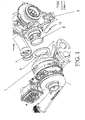
- Figs. 1-2 show the location of the seal 3 and the damper 4 in relation to the high pressure (HP) turbine housing 1 and the low pressure (LP) turbine housing 2 of a two-stage turbocharger.
- the seal 3 and the damper 4 according to the present disclosure can work under the following operating conditions: maximum temperature of approximately 750°C; approximate linear growth between housings of 1-2 mm; material for both castings of the housings 1, 2 is HiSiMo Iron; first mode of frequency is greater than 300 Hz; and minimum number of thermal cycles is approximately 10,000.
- the radial seal 3 can be made of knitted wire mesh of 300 series stainless steel and can have a wire diameter of about 0.20 mm.
- the present disclosure also contemplates the use of other materials based on a number of factors, such as cost (e.g., low carbon steel, 400 series stainless steel, etc.). However, due to moisture content in the exhaust gas and the nature of the iron housings, corrosion may occur which would limit the ability of the housings 1, 2 to grow/shrink as necessary without destroying the seal 3. Higher cost materials (e.g., nickel alloy, austenitic nickel-based superalloys, INCONEL®, etc.) can also be used although the benefit vs. cost should be considered.
- the diameter of the wire used to form the seal 3 can be in the range of 0.15 - 0.30 mm.
- the wire in the seal 3 can act as a skeleton to hold the lubricious material, such as vermiculite, graphite, etc., in a geometric shape and to provide some rigidity.
- the sealing capability of the part can be less sensitive to wire diameter.
- the impregnated mesh device can be in the shape of a thin-walled cylindrical ring and can be installed under compression inside the male/female joint formed by the male coupling structure 10 and the female coupling structure 20 that connect the two turbine housings 1, 2.
- the mesh seal 3 can have a thickness in the range of 3.0 - 6.0 mm and can have a density of 70-80% of wire content.
- the wire mesh seal 3 can be impregnated with vermiculite slurry.
- the seal 3 can also be impregnated with graphite or other suitable media.
- the vermiculite slurry, graphite or other suitable media can have properties as follows:
- the damper 4 can be made of knitted wire mesh, such as of 300 series stainless steel having a wire diameter of about 0.28 mm and a density of about 25%. In a preferred embodiment, the damper 4 is not impregnated. Similar to the seal 3, other lower or higher cost materials may also be used, but the possibility of corrosion and cost should be taken into consideration.
- the wire diameter of the damper 4 can be in the range of 0.10 - 0.40 mm. Unlike in the seal 3, it has been found that the wire diameter can be one of the critical characteristics of the damper 4. Along with density, these two characteristics allow "tuning" of the damper 4 to provide the necessary elastic modulus for thermal growth and vibration damping. Damper density can be dependant on thermal growth, necessary modal response and the wire diameter chosen. For the particular application in which these parts were designed, density should be limited to between 15 and 25%. Depending on the variables described, density could range anywhere from 10 - 80%. Depending on wire diameter, thermal growth and modal response, generally, 2.0 - 10.0 is a preferred range for the thickness of the damper 4.
- Seals have been used in exhaust manifolds and other pipe-type applications, while damper rings have also been used in other applications.
- the inventors of the present disclosure apply the seal 3 and damper 4 of the present disclosure together in a two-stage turbocharging system to decouple the exhaust joint in order to allow thermal growth of the housings 1, 2 while solving the problem of leak and modal response.
- seals have been used in exhaust manifold, it is a common perception that certain seals cannot be used in a turbocharger because the temperature is significantly higher in a turbocharger than in a regular exhaust manifold. Also, the problem of leaking is not as critical in a regular exhaust manifold as in a turbocharger.
Landscapes
- Engineering & Computer Science (AREA)
- General Engineering & Computer Science (AREA)
- Mechanical Engineering (AREA)
- Chemical & Material Sciences (AREA)
- Combustion & Propulsion (AREA)
- Gasket Seals (AREA)
- Supercharger (AREA)
Applications Claiming Priority (2)
| Application Number | Priority Date | Filing Date | Title |
|---|---|---|---|
| US82970206P | 2006-10-17 | 2006-10-17 | |
| PCT/US2007/081362 WO2008048918A1 (en) | 2006-10-17 | 2007-10-15 | Ring seals for gas sealing and vibration damping |
Publications (3)
| Publication Number | Publication Date |
|---|---|
| EP2079910A1 EP2079910A1 (en) | 2009-07-22 |
| EP2079910A4 EP2079910A4 (en) | 2013-07-17 |
| EP2079910B1 true EP2079910B1 (en) | 2015-01-07 |
Family
ID=39314354
Family Applications (1)
| Application Number | Title | Priority Date | Filing Date |
|---|---|---|---|
| EP07844284.5A Active EP2079910B1 (en) | 2006-10-17 | 2007-10-15 | Ring seals for gas sealing and vibration damping |
Country Status (6)
| Country | Link |
|---|---|
| US (1) | US8182206B2 (ja) |
| EP (1) | EP2079910B1 (ja) |
| JP (1) | JP4906924B2 (ja) |
| KR (1) | KR101258685B1 (ja) |
| CN (1) | CN101523027B (ja) |
| WO (1) | WO2008048918A1 (ja) |
Families Citing this family (17)
| Publication number | Priority date | Publication date | Assignee | Title |
|---|---|---|---|---|
| DE102008026025A1 (de) * | 2008-05-30 | 2009-09-03 | Voith Patent Gmbh | Antriebsstrang mit zwei Strömungsmaschinen, insbesondere Turboladern |
| AT507825B1 (de) * | 2009-02-03 | 2011-02-15 | Ge Jenbacher Gmbh & Co Ohg | Stationäre brennkraftmaschine |
| GB2472829B (en) * | 2009-08-20 | 2014-04-02 | Gm Global Tech Operations Inc | Two-stage turbocharged engine system |
| DE102009052167A1 (de) | 2009-11-06 | 2011-05-12 | Mtu Friedrichshafen Gmbh | Rohranordnung |
| DE102011101506B4 (de) * | 2010-05-17 | 2015-06-18 | GM Global Technology Operations LLC (n. d. Ges. d. Staates Delaware) | Motoranordnung und Verfahren zur Herstellung |
| DE102010047464B4 (de) * | 2010-10-06 | 2018-10-31 | Pierburg Gmbh | Befestigungsanordnung |
| JP5879685B2 (ja) | 2010-12-28 | 2016-03-08 | いすゞ自動車株式会社 | 多段過給装置 |
| WO2013033732A1 (en) * | 2011-09-01 | 2013-03-07 | Furnari Joseph | Rotational engine |
| US9109800B2 (en) * | 2011-10-18 | 2015-08-18 | General Electric Company | Quick disengaging field joint for exhaust system components of gas turbine engines |
| US10054005B1 (en) * | 2013-09-24 | 2018-08-21 | Florida Turbine Technologies, Inc | Turbocharger with oil-free hydrostatic bearing |
| DE112015000331B4 (de) | 2014-02-05 | 2022-07-14 | Borgwarner Inc. | Aufladevorrichtung |
| DE102014223415A1 (de) * | 2014-11-17 | 2016-05-19 | Wacker Chemie Ag | Vorrichtung zur Isolierung und Abdichtung von Elektrodenhalterungen in CVD Reaktoren |
| US10563771B2 (en) * | 2016-04-07 | 2020-02-18 | United Technologies Corporation | Wire mesh brush seal windage cover |
| DE102016212249B4 (de) * | 2016-07-05 | 2024-05-02 | Ford Global Technologies, Llc | Zweistufig aufladbare direkteinspritzende Brennkraftmaschine mit Abgasnachbehandlung und Verfahren zum Betreiben einer derartigen Brennkraftmaschine |
| KR20190028541A (ko) * | 2016-07-26 | 2019-03-18 | 플로리다 터빈 테크놀로지스, 인크. | 무급유 유정압 베어링을 구비한 터보차저 |
| DE102018212260A1 (de) * | 2018-07-24 | 2020-01-30 | Continental Automotive Gmbh | Abgasturbolader mit optimiertem akustischen Verhalten |
| EP3967858A1 (de) * | 2020-09-14 | 2022-03-16 | ABB Schweiz AG | Mehrstufige turboladeranordnung |
Family Cites Families (16)
| Publication number | Priority date | Publication date | Assignee | Title |
|---|---|---|---|---|
| CH584351A5 (ja) * | 1974-12-18 | 1977-01-31 | Bbc Brown Boveri & Cie | |
| US4607851A (en) * | 1977-11-30 | 1986-08-26 | Metex Corporation | Method of making composite wire mesh seal |
| DE2965419D1 (en) * | 1979-02-19 | 1983-07-07 | Bbc Brown Boveri & Cie | Exhaust-gas driven turbocharger having two stages |
| US4339922A (en) * | 1979-07-09 | 1982-07-20 | Navarro Bernard J | Dual turbine turbo-supercharger |
| FR2629863B1 (fr) * | 1988-04-12 | 1991-02-08 | Dubois Jacques | Accouplement d'echappement flexible |
| JP2566525B2 (ja) * | 1993-10-18 | 1996-12-25 | 日本ピラー工業株式会社 | 差込みフランジ用ガスケット |
| US6029452A (en) * | 1995-11-15 | 2000-02-29 | Turbodyne Systems, Inc. | Charge air systems for four-cycle internal combustion engines |
| US6464257B1 (en) * | 1997-04-10 | 2002-10-15 | Senior Investments Ag | Vibration decoupler apparatus |
| JP2001262458A (ja) * | 2000-03-15 | 2001-09-26 | Aisin Seiki Co Ltd | ミシン及び縫製物保持装置 |
| US6312022B1 (en) * | 2000-03-27 | 2001-11-06 | Metex Mfg. Corporation | Pipe joint and seal |
| US6357234B1 (en) | 2000-09-21 | 2002-03-19 | Caterpillar Inc. | Turbocharger system with turbines having independently controlled variable nozzles |
| US7017706B2 (en) * | 2001-12-21 | 2006-03-28 | Honeywell International, Inc. | Turbine noise absorber |
| US6921112B2 (en) * | 2002-11-26 | 2005-07-26 | Josif Atansoski | Exhaust vibration decoupling connector |
| CN2615345Y (zh) * | 2003-04-14 | 2004-05-12 | 邱信国 | 高效密封涡轮增压器 |
| SE525218C2 (sv) * | 2003-05-15 | 2004-12-28 | Volvo Lastvagnar Ab | Turboladdarsystem för en förbränningsmotor innefattande två seriellt och väsentligen koncentriskt med rotationsaxlarna placerade turboenheter |
| CN1560441A (zh) * | 2004-03-11 | 2005-01-05 | 孙敏超 | 高增压柴油机用的一种双轴二级涡轮增压器 |
-
2007
- 2007-10-15 KR KR1020097007737A patent/KR101258685B1/ko active IP Right Grant
- 2007-10-15 CN CN2007800363323A patent/CN101523027B/zh not_active Expired - Fee Related
- 2007-10-15 WO PCT/US2007/081362 patent/WO2008048918A1/en active Application Filing
- 2007-10-15 JP JP2009533459A patent/JP4906924B2/ja not_active Expired - Fee Related
- 2007-10-15 EP EP07844284.5A patent/EP2079910B1/en active Active
- 2007-10-15 US US12/442,170 patent/US8182206B2/en active Active
Also Published As
| Publication number | Publication date |
|---|---|
| CN101523027A (zh) | 2009-09-02 |
| JP2010507045A (ja) | 2010-03-04 |
| KR101258685B1 (ko) | 2013-04-30 |
| WO2008048918A1 (en) | 2008-04-24 |
| CN101523027B (zh) | 2011-05-25 |
| US8182206B2 (en) | 2012-05-22 |
| KR20090069177A (ko) | 2009-06-29 |
| EP2079910A4 (en) | 2013-07-17 |
| EP2079910A1 (en) | 2009-07-22 |
| JP4906924B2 (ja) | 2012-03-28 |
| US20090252599A1 (en) | 2009-10-08 |
Similar Documents
| Publication | Publication Date | Title |
|---|---|---|
| EP2079910B1 (en) | Ring seals for gas sealing and vibration damping | |
| US7360362B2 (en) | Two-stage turbocharger system with integrated exhaust manifold and bypass assembly | |
| US8376721B2 (en) | Turbine heat shield assembly | |
| CA2448458C (en) | Turbocharged internal combustion engine | |
| WO2009114568A3 (en) | Exhaust manifold of an internal combustion engine | |
| JP5390605B2 (ja) | 内燃機関のエグゾーストターボチャージャ用タービンハウジング | |
| EP2683925B1 (en) | Method for upgrading an engine, upgrade kit for an engine and internal combustion engine | |
| JP4387411B2 (ja) | 回転軸が事実上同軸の二つの直列に配置したターボユニットを有する内燃エンジンのためのターボコンプレッサシステム | |
| CN107605604B (zh) | 一种可适应内外环机匣非协调热变形的封严及辅助定位结构 | |
| CN1851247B (zh) | 用于内燃机的废气涡轮增压器 | |
| EP2792868B1 (en) | Exhaust turbine supercharger | |
| US20060086090A1 (en) | Vibration limiter for coaxial shafts and compound turbocharger using same | |
| EP2341225A1 (en) | Method for controlling a turbocompound engine apparatus | |
| US11060478B2 (en) | System for an integrated hybrid composite cylinder head and turbine | |
| US10550705B2 (en) | Turbine exhaust seal | |
| EP2612005B1 (en) | Exhaust module and internal combustion engine | |
| US10087940B2 (en) | Exhaust turbine assembly | |
| USH2293H1 (en) | Pivot shaft seal | |
| CN207421585U (zh) | 法兰连接器 | |
| Srivastava et al. | Investigation of a Variable Geometry Turbine Nozzle for Diesel Engine Turbochargers | |
| JP2021113522A (ja) | 補強構造 | |
| JPS6245046Y2 (ja) | ||
| CN114687804A (zh) | 一种涡轮增压器的涡轮轴 | |
| WO2015033844A1 (ja) | タービン、ターボ過給機、内燃機関、及び船舶 |
Legal Events
| Date | Code | Title | Description |
|---|---|---|---|
| PUAI | Public reference made under article 153(3) epc to a published international application that has entered the european phase |
Free format text: ORIGINAL CODE: 0009012 |
|
| 17P | Request for examination filed |
Effective date: 20090422 |
|
| AK | Designated contracting states |
Kind code of ref document: A1 Designated state(s): AT BE BG CH CY CZ DE DK EE ES FI FR GB GR HU IE IS IT LI LT LU LV MC MT NL PL PT RO SE SI SK TR |
|
| RIN1 | Information on inventor provided before grant (corrected) |
Inventor name: CARTER, DAVID Inventor name: CAVAGNARO, AUGUSTINE |
|
| DAX | Request for extension of the european patent (deleted) | ||
| RIC1 | Information provided on ipc code assigned before grant |
Ipc: F02B 37/00 20060101ALI20130605BHEP Ipc: F02B 39/00 20060101AFI20130605BHEP Ipc: F02B 39/16 20060101ALI20130605BHEP Ipc: F02B 37/013 20060101ALI20130605BHEP |
|
| A4 | Supplementary search report drawn up and despatched |
Effective date: 20130613 |
|
| RIC1 | Information provided on ipc code assigned before grant |
Ipc: F02B 39/16 20060101ALI20130607BHEP Ipc: F02B 37/013 20060101ALI20130607BHEP Ipc: F02B 37/00 20060101ALI20130607BHEP Ipc: F02B 39/00 20060101AFI20130607BHEP |
|
| GRAP | Despatch of communication of intention to grant a patent |
Free format text: ORIGINAL CODE: EPIDOSNIGR1 |
|
| RIC1 | Information provided on ipc code assigned before grant |
Ipc: F02B 39/16 20060101ALI20140822BHEP Ipc: F16J 15/12 20060101ALI20140822BHEP Ipc: F02B 67/10 20060101ALI20140822BHEP Ipc: F02B 37/00 20060101ALI20140822BHEP Ipc: F02B 37/013 20060101ALI20140822BHEP Ipc: F02B 39/00 20060101AFI20140822BHEP |
|
| INTG | Intention to grant announced |
Effective date: 20140930 |
|
| GRAS | Grant fee paid |
Free format text: ORIGINAL CODE: EPIDOSNIGR3 |
|
| GRAA | (expected) grant |
Free format text: ORIGINAL CODE: 0009210 |
|
| AK | Designated contracting states |
Kind code of ref document: B1 Designated state(s): AT BE BG CH CY CZ DE DK EE ES FI FR GB GR HU IE IS IT LI LT LU LV MC MT NL PL PT RO SE SI SK TR |
|
| REG | Reference to a national code |
Ref country code: GB Ref legal event code: FG4D |
|
| REG | Reference to a national code |
Ref country code: CH Ref legal event code: EP |
|
| REG | Reference to a national code |
Ref country code: IE Ref legal event code: FG4D |
|
| REG | Reference to a national code |
Ref country code: AT Ref legal event code: REF Ref document number: 705898 Country of ref document: AT Kind code of ref document: T Effective date: 20150215 |
|
| REG | Reference to a national code |
Ref country code: DE Ref legal event code: R096 Ref document number: 602007040000 Country of ref document: DE Effective date: 20150226 |
|
| REG | Reference to a national code |
Ref country code: NL Ref legal event code: VDEP Effective date: 20150107 |
|
| REG | Reference to a national code |
Ref country code: AT Ref legal event code: MK05 Ref document number: 705898 Country of ref document: AT Kind code of ref document: T Effective date: 20150107 |
|
| REG | Reference to a national code |
Ref country code: LT Ref legal event code: MG4D |
|
| PG25 | Lapsed in a contracting state [announced via postgrant information from national office to epo] |
Ref country code: FI Free format text: LAPSE BECAUSE OF FAILURE TO SUBMIT A TRANSLATION OF THE DESCRIPTION OR TO PAY THE FEE WITHIN THE PRESCRIBED TIME-LIMIT Effective date: 20150107 Ref country code: SE Free format text: LAPSE BECAUSE OF FAILURE TO SUBMIT A TRANSLATION OF THE DESCRIPTION OR TO PAY THE FEE WITHIN THE PRESCRIBED TIME-LIMIT Effective date: 20150107 Ref country code: ES Free format text: LAPSE BECAUSE OF FAILURE TO SUBMIT A TRANSLATION OF THE DESCRIPTION OR TO PAY THE FEE WITHIN THE PRESCRIBED TIME-LIMIT Effective date: 20150107 Ref country code: BG Free format text: LAPSE BECAUSE OF FAILURE TO SUBMIT A TRANSLATION OF THE DESCRIPTION OR TO PAY THE FEE WITHIN THE PRESCRIBED TIME-LIMIT Effective date: 20150407 Ref country code: LT Free format text: LAPSE BECAUSE OF FAILURE TO SUBMIT A TRANSLATION OF THE DESCRIPTION OR TO PAY THE FEE WITHIN THE PRESCRIBED TIME-LIMIT Effective date: 20150107 |
|
| PG25 | Lapsed in a contracting state [announced via postgrant information from national office to epo] |
Ref country code: PL Free format text: LAPSE BECAUSE OF FAILURE TO SUBMIT A TRANSLATION OF THE DESCRIPTION OR TO PAY THE FEE WITHIN THE PRESCRIBED TIME-LIMIT Effective date: 20150107 Ref country code: LV Free format text: LAPSE BECAUSE OF FAILURE TO SUBMIT A TRANSLATION OF THE DESCRIPTION OR TO PAY THE FEE WITHIN THE PRESCRIBED TIME-LIMIT Effective date: 20150107 Ref country code: AT Free format text: LAPSE BECAUSE OF FAILURE TO SUBMIT A TRANSLATION OF THE DESCRIPTION OR TO PAY THE FEE WITHIN THE PRESCRIBED TIME-LIMIT Effective date: 20150107 Ref country code: GR Free format text: LAPSE BECAUSE OF FAILURE TO SUBMIT A TRANSLATION OF THE DESCRIPTION OR TO PAY THE FEE WITHIN THE PRESCRIBED TIME-LIMIT Effective date: 20150408 Ref country code: IS Free format text: LAPSE BECAUSE OF FAILURE TO SUBMIT A TRANSLATION OF THE DESCRIPTION OR TO PAY THE FEE WITHIN THE PRESCRIBED TIME-LIMIT Effective date: 20150507 Ref country code: NL Free format text: LAPSE BECAUSE OF FAILURE TO SUBMIT A TRANSLATION OF THE DESCRIPTION OR TO PAY THE FEE WITHIN THE PRESCRIBED TIME-LIMIT Effective date: 20150107 |
|
| REG | Reference to a national code |
Ref country code: DE Ref legal event code: R097 Ref document number: 602007040000 Country of ref document: DE |
|
| PG25 | Lapsed in a contracting state [announced via postgrant information from national office to epo] |
Ref country code: CZ Free format text: LAPSE BECAUSE OF FAILURE TO SUBMIT A TRANSLATION OF THE DESCRIPTION OR TO PAY THE FEE WITHIN THE PRESCRIBED TIME-LIMIT Effective date: 20150107 Ref country code: RO Free format text: LAPSE BECAUSE OF FAILURE TO SUBMIT A TRANSLATION OF THE DESCRIPTION OR TO PAY THE FEE WITHIN THE PRESCRIBED TIME-LIMIT Effective date: 20150107 Ref country code: DK Free format text: LAPSE BECAUSE OF FAILURE TO SUBMIT A TRANSLATION OF THE DESCRIPTION OR TO PAY THE FEE WITHIN THE PRESCRIBED TIME-LIMIT Effective date: 20150107 Ref country code: SK Free format text: LAPSE BECAUSE OF FAILURE TO SUBMIT A TRANSLATION OF THE DESCRIPTION OR TO PAY THE FEE WITHIN THE PRESCRIBED TIME-LIMIT Effective date: 20150107 Ref country code: EE Free format text: LAPSE BECAUSE OF FAILURE TO SUBMIT A TRANSLATION OF THE DESCRIPTION OR TO PAY THE FEE WITHIN THE PRESCRIBED TIME-LIMIT Effective date: 20150107 |
|
| PLBE | No opposition filed within time limit |
Free format text: ORIGINAL CODE: 0009261 |
|
| STAA | Information on the status of an ep patent application or granted ep patent |
Free format text: STATUS: NO OPPOSITION FILED WITHIN TIME LIMIT |
|
| 26N | No opposition filed |
Effective date: 20151008 |
|
| PG25 | Lapsed in a contracting state [announced via postgrant information from national office to epo] |
Ref country code: IT Free format text: LAPSE BECAUSE OF FAILURE TO SUBMIT A TRANSLATION OF THE DESCRIPTION OR TO PAY THE FEE WITHIN THE PRESCRIBED TIME-LIMIT Effective date: 20150107 |
|
| PG25 | Lapsed in a contracting state [announced via postgrant information from national office to epo] |
Ref country code: SI Free format text: LAPSE BECAUSE OF FAILURE TO SUBMIT A TRANSLATION OF THE DESCRIPTION OR TO PAY THE FEE WITHIN THE PRESCRIBED TIME-LIMIT Effective date: 20150107 |
|
| PG25 | Lapsed in a contracting state [announced via postgrant information from national office to epo] |
Ref country code: LU Free format text: LAPSE BECAUSE OF FAILURE TO SUBMIT A TRANSLATION OF THE DESCRIPTION OR TO PAY THE FEE WITHIN THE PRESCRIBED TIME-LIMIT Effective date: 20151015 Ref country code: BE Free format text: LAPSE BECAUSE OF FAILURE TO SUBMIT A TRANSLATION OF THE DESCRIPTION OR TO PAY THE FEE WITHIN THE PRESCRIBED TIME-LIMIT Effective date: 20150107 |
|
| REG | Reference to a national code |
Ref country code: CH Ref legal event code: PL |
|
| GBPC | Gb: european patent ceased through non-payment of renewal fee |
Effective date: 20151015 |
|
| PG25 | Lapsed in a contracting state [announced via postgrant information from national office to epo] |
Ref country code: MC Free format text: LAPSE BECAUSE OF FAILURE TO SUBMIT A TRANSLATION OF THE DESCRIPTION OR TO PAY THE FEE WITHIN THE PRESCRIBED TIME-LIMIT Effective date: 20150107 |
|
| REG | Reference to a national code |
Ref country code: IE Ref legal event code: MM4A |
|
| PG25 | Lapsed in a contracting state [announced via postgrant information from national office to epo] |
Ref country code: CH Free format text: LAPSE BECAUSE OF NON-PAYMENT OF DUE FEES Effective date: 20151031 Ref country code: LI Free format text: LAPSE BECAUSE OF NON-PAYMENT OF DUE FEES Effective date: 20151031 Ref country code: GB Free format text: LAPSE BECAUSE OF NON-PAYMENT OF DUE FEES Effective date: 20151015 |
|
| REG | Reference to a national code |
Ref country code: FR Ref legal event code: ST Effective date: 20160630 |
|
| PG25 | Lapsed in a contracting state [announced via postgrant information from national office to epo] |
Ref country code: FR Free format text: LAPSE BECAUSE OF NON-PAYMENT OF DUE FEES Effective date: 20151102 |
|
| PG25 | Lapsed in a contracting state [announced via postgrant information from national office to epo] |
Ref country code: IE Free format text: LAPSE BECAUSE OF NON-PAYMENT OF DUE FEES Effective date: 20151015 |
|
| PG25 | Lapsed in a contracting state [announced via postgrant information from national office to epo] |
Ref country code: HU Free format text: LAPSE BECAUSE OF FAILURE TO SUBMIT A TRANSLATION OF THE DESCRIPTION OR TO PAY THE FEE WITHIN THE PRESCRIBED TIME-LIMIT; INVALID AB INITIO Effective date: 20071015 |
|
| PG25 | Lapsed in a contracting state [announced via postgrant information from national office to epo] |
Ref country code: CY Free format text: LAPSE BECAUSE OF FAILURE TO SUBMIT A TRANSLATION OF THE DESCRIPTION OR TO PAY THE FEE WITHIN THE PRESCRIBED TIME-LIMIT Effective date: 20150107 |
|
| PG25 | Lapsed in a contracting state [announced via postgrant information from national office to epo] |
Ref country code: TR Free format text: LAPSE BECAUSE OF FAILURE TO SUBMIT A TRANSLATION OF THE DESCRIPTION OR TO PAY THE FEE WITHIN THE PRESCRIBED TIME-LIMIT Effective date: 20150107 Ref country code: MT Free format text: LAPSE BECAUSE OF FAILURE TO SUBMIT A TRANSLATION OF THE DESCRIPTION OR TO PAY THE FEE WITHIN THE PRESCRIBED TIME-LIMIT Effective date: 20150107 |
|
| PG25 | Lapsed in a contracting state [announced via postgrant information from national office to epo] |
Ref country code: PT Free format text: LAPSE BECAUSE OF FAILURE TO SUBMIT A TRANSLATION OF THE DESCRIPTION OR TO PAY THE FEE WITHIN THE PRESCRIBED TIME-LIMIT Effective date: 20150107 |
|
| PGFP | Annual fee paid to national office [announced via postgrant information from national office to epo] |
Ref country code: DE Payment date: 20220914 Year of fee payment: 16 |
|
| P01 | Opt-out of the competence of the unified patent court (upc) registered |
Effective date: 20230327 |