EP2078782A1 - Verfahren zur Herstellung eines Türringes für eine Tür einer frontbeschickbaren Wäschebehandlungsmaschine - Google Patents
Verfahren zur Herstellung eines Türringes für eine Tür einer frontbeschickbaren Wäschebehandlungsmaschine Download PDFInfo
- Publication number
- EP2078782A1 EP2078782A1 EP08022120A EP08022120A EP2078782A1 EP 2078782 A1 EP2078782 A1 EP 2078782A1 EP 08022120 A EP08022120 A EP 08022120A EP 08022120 A EP08022120 A EP 08022120A EP 2078782 A1 EP2078782 A1 EP 2078782A1
- Authority
- EP
- European Patent Office
- Prior art keywords
- torus
- ring
- shaped
- door
- tube
- Prior art date
- Legal status (The legal status is an assumption and is not a legal conclusion. Google has not performed a legal analysis and makes no representation as to the accuracy of the status listed.)
- Granted
Links
- 238000000034 method Methods 0.000 title claims abstract description 26
- 238000004519 manufacturing process Methods 0.000 title claims description 7
- 229910052751 metal Inorganic materials 0.000 claims abstract description 14
- 239000002184 metal Substances 0.000 claims abstract description 14
- 238000005520 cutting process Methods 0.000 claims abstract 2
- 239000011521 glass Substances 0.000 claims description 5
- 239000000463 material Substances 0.000 claims description 4
- 229910000831 Steel Inorganic materials 0.000 claims description 2
- 229910052782 aluminium Inorganic materials 0.000 claims description 2
- XAGFODPZIPBFFR-UHFFFAOYSA-N aluminium Chemical compound [Al] XAGFODPZIPBFFR-UHFFFAOYSA-N 0.000 claims description 2
- 239000010959 steel Substances 0.000 claims description 2
- 238000005452 bending Methods 0.000 claims 1
- 238000003466 welding Methods 0.000 claims 1
- 238000003825 pressing Methods 0.000 abstract description 3
- HCHKCACWOHOZIP-UHFFFAOYSA-N Zinc Chemical compound [Zn] HCHKCACWOHOZIP-UHFFFAOYSA-N 0.000 description 3
- 238000004512 die casting Methods 0.000 description 3
- 239000000203 mixture Substances 0.000 description 3
- 238000000926 separation method Methods 0.000 description 3
- 229910052725 zinc Inorganic materials 0.000 description 3
- 239000011701 zinc Substances 0.000 description 3
- 244000089486 Phragmites australis subsp australis Species 0.000 description 2
- 238000005034 decoration Methods 0.000 description 2
- 238000011161 development Methods 0.000 description 2
- 230000018109 developmental process Effects 0.000 description 2
- 230000000149 penetrating effect Effects 0.000 description 2
- 238000007493 shaping process Methods 0.000 description 2
- 230000007613 environmental effect Effects 0.000 description 1
- 230000003287 optical effect Effects 0.000 description 1
- 238000005498 polishing Methods 0.000 description 1
- 238000005406 washing Methods 0.000 description 1
- 239000002699 waste material Substances 0.000 description 1
Images



Classifications
-
- D—TEXTILES; PAPER
- D06—TREATMENT OF TEXTILES OR THE LIKE; LAUNDERING; FLEXIBLE MATERIALS NOT OTHERWISE PROVIDED FOR
- D06F—LAUNDERING, DRYING, IRONING, PRESSING OR FOLDING TEXTILE ARTICLES
- D06F37/00—Details specific to washing machines covered by groups D06F21/00 - D06F25/00
- D06F37/26—Casings; Tubs
-
- B—PERFORMING OPERATIONS; TRANSPORTING
- B21—MECHANICAL METAL-WORKING WITHOUT ESSENTIALLY REMOVING MATERIAL; PUNCHING METAL
- B21D—WORKING OR PROCESSING OF SHEET METAL OR METAL TUBES, RODS OR PROFILES WITHOUT ESSENTIALLY REMOVING MATERIAL; PUNCHING METAL
- B21D53/00—Making other particular articles
- B21D53/16—Making other particular articles rings, e.g. barrel hoops
Definitions
- the invention relates to a method for producing a door ring for a door of a front loadable laundry treating machine, which is attached from the outside as a cover ring / trim ring on the door glass enclosing, hinged ring.
- Such known from the prior art cover / trim rings are set as an optical termination on the door glass enclosing, hinged ring.
- These known rings are made by a zinc die casting process. They have in particular the disadvantage that they are very high in their production of the material costs, in particular, the execution in zinc die-casting, also in terms of weight, is also unfavorable. It is also known, for example, to replace the zinc die casting solution by a sheet metal solution, wherein the sheet metal door ring is made by a pressing or pressing process. In the case of the metal door ring, however, there is the disadvantage that it has distortion tendencies. This results in drawing marks and grooves, which in turn leads to a high grinding and polishing costs in such covering or decorative rings. In addition, the deep drawing process has the disadvantage that it has high waste costs in the production.
- the invention thus presents the problem of providing a method for producing a door ring for a door of a front loading laundry treating machine, which overcomes the disadvantages, in particular the high material costs are reduced.
- the method according to the invention for producing the covering / ornamental ring comprises the following method steps. First, a pipe with a defined diameter and a defined wall thickness is cut to size. The cut pipe is then bent into a torus to form an annular, hollow body. The abutting ends of the bent tube are then welded together to form a stable, hollow body. Thereafter, at a location of the circumference of the curved torus, a Toruswand penetrating nozzle is attached, which is intended in particular for the introduction of an incompressible medium. Thereafter, the curved torus is placed with the attached nozzle in an at least two-part mold surrounding the curved torus, the opening or the free end of the attached nozzle remains accessible from the outside.
- the torus is subjected to the incompressible medium through the attached neck, in such a way that, in particular, the torus wall bears against the inner wall of the mold, so that a hollow body shaped part is formed, which corresponds to the mold wall.
- the mold is opened again and the molded hollow body removed from the mold, so that a molded hollow body has formed in the manner of a rim. If the molded hollow body is then separated by means of a separating cut in the radial axis or plane, two partial rings are obtained.
- the separation section is placed in the radial axis of symmetry, so that two substantially identical partial rings arise. This gives you with a separating cut two equal partial rings simultaneously.
- the shaped torus in order to obtain correspondingly attachable door rings or cover rings, is separated at the inner and outer edge.
- the shaped torus has at the center of the ring V-shaped legs, are formed on the parallel webs, which merge into a transverse edge forming the outer edge.
- a groove is formed at the intersection of the V-legs, wherein also in each case on the parallel webs outwardly facing grooves are formed out.
- the separating cut is made once in the intersection of the V-legs in the groove, on the other hand, two separating cuts are provided on the outer edge and that here on the grooves, which formed outwardly pointing to the parallel webs are. As rest or as a blend then only remains only the between the two grooves on the outer ring remaining crosspiece, so that here two identical attachable rings can be created with a shaped torus.
- the cover or trim ring is made of a steel tube.
- the trim ring is made of an aluminum material.
- FIG. 1 shows an open door 1 on a front loadable laundry treating machine 2, wherein the door 1 comprises a door glass 4 enclosing ring 5, on the outside of a cover / trim ring 3 is mounted.
- the ring 5 is hinged on one side to the edge of the loading opening on the front wall of the laundry treatment machine 2.
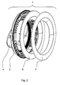
- a retaining ring 6 is attached to the hinged ring 5, on which then finally produced by the method covering / trim ring 3 is recognized.
- the door glass 4 is attached to the ring 5 and has a to the inside of the machine 2 ( Fig. 1 ) pointing vault when the door 1 is closed.
- a metal tube 7 with a defined diameter and a defined wall thickness, as shown in the FIG. 3 7 is cut to a defined length, the length corresponding to the circumference of the yet to be bent torus 8.
- This tube 7 is then, as in the FIG. 4 is bent to a ring or torus 8, so that the ends of the tube 7 abut each other.
- the joint 9 is welded together flush, so that as in the FIG. 4 shown Metallrohrtorus 8 results.
- a penetrating nozzle not shown in detail, attached to the Metallrohrtorus 8, through which then the incompressible medium is pressed. Before this happens, the thus formed and produced torus 8 according to the FIG.
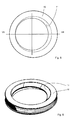
- the corresponding hollow shaped body 10 in front view is in the FIG. 5 shown here, it being conspicuous that the inner ring 11 is formed sickle-shaped.
- This sickle shape designed the opening cross-section of the cover or trim ring 3 such that from the front of the washing machine 2 forth the upper region has a kind of funnel-shaped design, whereas the lower portion of the trim ring 3 is formed flat, so that from top to bottom in the Top view of this sickle shape results.
- the hollow shaped body 10 is shaped as in the FIGS. 5 and 6 shown. This is followed, in particular, by a separation of the shaped hollow body 10, in which case a radial separating cut is made on the hollow shaped body 10 in such a way that two identical partial rings 12.1 and 12.2 result, as shown in FIG FIG. 8 is shown. In this case, the separating cut is made such that the shaped torus 8 is separated at the inner and outer edges.
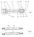
- the shape of the hollow body 10 results in the following shape, which is clear in the sectional view of FIG. 7 where in particular the section line corresponding to the section line VII-VII in the FIG. 5 is shown.
- Diametrically opposite results as a result of the sickle shape, as described above, then the following picture that there the V-shaped legs 13.3 and 13.4 expand to the diametrically opposite side of the ring 3, so that they occupy an almost horizontal position.
- a encircling groove 16 integrally formed, and also according to the outside on the parallel webs 14.1 and 14.2 outwardly facing webs 17.1 and 17.2 are formed, which merge into the, the outer edge forming crosspiece 15, and where now the separating cut, as he is shown in the FIG. 9 , Once through the groove 16 between the V-legs 13.1 and 13.2 and formed by the formed on the outer edge webs 17.1 and 17.2.
- FIG. 9 represents, where again according to the FIG. 2 , the individual elements forming the door 1 are shown in the exploded view.
Landscapes
- Engineering & Computer Science (AREA)
- Textile Engineering (AREA)
- Mechanical Engineering (AREA)
- Main Body Construction Of Washing Machines And Laundry Dryers (AREA)
- Storage Of Web-Like Or Filamentary Materials (AREA)
- Treatment Of Fiber Materials (AREA)
Abstract
Description
- Die Erfindung betrifft ein Verfahren zur Herstellung eines Türringes für eine Tür einer frontbeschickbaren Wäschebehandlungsmaschine, der von außen als Abdeckring /Zierring auf den das Türglas einfassenden, anscharnierten Ring angesetzt wird.
- Derartige aus dem Stand der Technik bekannte Abdeck-/Zierringe werden als optischer Abschluss auf den das Türglas einfassenden, anscharnierten Ring gesetzt. Diese bekannten Ringe werden nach einem Zinkdruckgussverfahren hergestellt. Sie weisen dabei insbesondere den Nachteil auf, dass sie in ihrer Herstellungsart von den Materialkosten sehr hoch ausfallen, wobei insbesondere die Ausführung in Zinkdruckguss, auch was das Gewicht betrifft, ebenfalls ungünstig ist. Auch ist es bekannt, beispielsweise die Zinkdruckguss-Lösung durch eine Blech-Lösung zu ersetzen, wobei der Blechtürring über ein Drück- oder Pressverfahren gefertigt wird. Bei dem Blechtürring ergibt sich jedoch der Nachteil, dass er Verzugsneigungen aufweist. So ergeben sich Ziehspuren und Riefen, was wiederum zu einem hohen Schleif- und Polieraufwand bei derartigen Abdeck- bzw. Zierringen führt. Zudem birgt das Tiefziehverfahren den Nachteil, dass es bei der Fertigung hohe Verschnittkosten aufweist.
- Aus der
DE 10 2006 026 717 A1 ist es bekannt, eine Kunststofftür an der Frontseite mit einem Dekorationsteil aus einer Metallschicht zu versehen. Hierbei wird das Dekorationsteil auf dem Kunststoffrahmen aufgeklebt, wobei hierbei eine besonders hohe Genauigkeit und Sorgfalt bei der Formgebung erforderlich ist, damit im frontseitigen Sichtbereich keine sichtbaren Spalten entstehen. Ferner ist der Kunststoffrahmen außenseitig nicht vollständig abgedeckt, so dass Teile des Kunststoffrahmens den Umgebungseinflüssen ausgesetzt bzw. zumindest für den Benutzer sichtbar sind. - Der Erfindung stellt sich somit das Problem, ein Verfahren zur Herstellung eines Türringes für eine Tür einer frontbeschickbaren Wäschebehandlungsmaschine bereit zu stellen, das die aufgezeigten Nachteile überwindet, wobei insbesondere die hohen Materialkosten reduziert werden.
- Erfindungsgemäß wird dieses Problem durch ein Verfahren mit den Merkmalen des Anspruchs 1 gelöst. Vorteilhafte Weiterbildungen der Erfindung ergeben sich aus den nachfolgenden Unteransprüchen.
- Die mit der Erfindung erreichten Vorteile sind insbesondere darin zu sehen, dass einerseits mit dem erfindungsgemäßen Verfahren eine wesentlich verbesserte Oberflächenqualität des Abdeck-/Zierringes erzielt wird, wobei andererseits Verschnitte so gut wie gänzlich vermieden werden bzw. zumindest sehr gering ausfallen.
- Hierzu umfasst das erfindungsgemäße Verfahren zur Herstellung des Abdeck-/Zierringes folgende Verfahrensschritte. Zunächst wird ein Rohr mit einem definierten Durchmesser sowie einer definierten Wandstärke auf Maß abgelängt. Das abgelängte Rohr wird dann zu einem Torus gebogen, so dass sich ein ringförmiger, hohler Körper bildet. Die voreinander stoßenden Enden des gebogenen Rohres werden dann miteinander verschweißt, so dass ein stabiler, hohler Körper entsteht. Danach wird an einer Stelle des Umfanges des gebogenen Torus ein die Toruswand durchdringender Stutzen angebracht, der insbesondere für das Einbringen eines inkompressiblen Mediums bestimmt ist. Danach wird der gebogene Torus mit dem angesetzten Stutzen in eine zumindest zweiteilige Form eingelegt, die den gebogenen Torus umgibt, wobei die Öffnung bzw. das freie Ende des angesetzten Stutzens von außen zugänglich bleibt. Danach wird durch den angesetzten Stutzen der Torus mit dem inkompressiblen Medium beaufschlagt, in der Art, dass sich insbesondere die Toruswand an die Innenwand der Form anlegt, so dass sich ein Hohlkörperformteil bildet, welches der Formwandung entspricht. Danach wird die Form wieder geöffnet und der geformte Hohlkörper aus der Form herausgenommen, so dass sich ein Formhohlkörper nach Art einer Felge gebildet hat. Wird dann der geformte Hohlkörper mittels eines Trennschnittes in der radialen Achse bzw. Ebene getrennt, so erhält man zwei Teilringe.
- In einer vorteilhaften Ausführung wird der Trennschnitt in der radialen Symmetrieachse gelegt, so dass zwei im Wesentlichen identische Teilringe entstehen. Damit erhält man mit einem Trennschnitt gleichzeitig zwei gleiche Teilringe.
- Nach einer vorteilhaften Weiterbildung der Erfindung, um hier entsprechend ansetzbare Türringe bzw. Abdeckringe zu erhalten, wird der geformte Torus am inneren und äußeren Rand getrennt. Der geformte Torus weist zum Mittelpunkt des Rings V-förmig geformte Schenkel auf, an die parallel verlaufende Stege angeformt sind, die in einen den äußeren Rand bildenden Quersteg übergehen. Dabei wird bei der Formung vorgesehen, dass im Schnittpunkt der V-Schenkel eine Nut eingeformt wird, wobei ebenfalls jeweils an den parallel verlaufenden Stegen nach außen weisende Nuten herausgeformt sind. Um insbesondere einen passgenauen ansetzbaren Zierring zu erhalten, wird daher der Trennschnitt einmal im Schnittpunkt der V-Schenkel in der Nut vorgenommen, wobei andererseits zwei Trennschnitte am Außenrand und zwar hier an den Nuten vorgesehen werden, die an den parallel verlaufenden Stegen nach außen weisend geformt sind. Als Rest bzw. als Verschnitt verbleibt dann lediglich nur der zwischen den beiden Nuten am Außenring verbleibende Quersteg, so dass hier zwei identische ansetzbare Ringe mit einem geformten Torus erstellt werden können.
- In vorteilhafter Weiterbildung der Erfindung ist hierbei der Abdeck- bzw. Zierring aus einem Stahlrohr gefertigt. In einer alternativen Ausführungsform ist der Zierring aus einem Aluminiummaterial gefertigt.
- Ein Ausführungsbeispiel der Erfindung wird anhand der nachstehenden
Figuren 1 bis 9 näher beschrieben; es zeigen: - Figur 1
- eine perspektivische Darstellung einer frontbeschickbaren Wäschebehandlungs- maschine mit geöffneter Tür,
- Figur 2
- eine explosionsartige Darstellung einer anscharnierten Tür einer frontbeschick- baren Wäschebehandlungsmaschine;
- Figur 3
- eine isolierte Darstellung eines Rohres gemäß dem Verfahren;
- Figur 4
- eine weitere perspektivische Darstellung des gebogenen Rohres gemäß dem Verfahren;
- Figur 5
- eine Frontansicht des geformten Torus gemäß dem Verfahren;
- Figur 6
- eine perspektivische Darstellung des geformten Torus gemäß dem Verfahren;
- Figur 7
- eine geschnittene Ansicht des geformten Torus gemäß der Schnittlinie VII-VII in
Figur 5 ; - Figur 8
- eine geschnittene Darstellung des geformten Torus gemäß dem Verfahren nach dem Trennschnitt und
- Figur 9
- eine explosionsartige Darstellung des geformten Abdeck- bzw. Türringes geformt nach dem Verfahren in einer geschnittenen Seitenansicht.
- Die
Figur 1 zeigt eine geöffnete Tür 1 an einer frontbeschickbaren Wäschebehandlungsmaschine 2, wobei die Tür 1 einen ein Türglas 4 einfassenden Ring 5 umfasst, auf den von außen ein Abdeck-/Zierring 3 angebracht ist. Der Ring 5 ist an einer Seite am Rand der Beladungsöffnung an der Frontwand der Wäschebehandlungsmaschine 2 anscharniert. In der isolierten Darstellung derFigur 2 wird deutlich, dass auf den anscharnierten Ring 5 ein Haltering 6 angesetzt ist, auf den dann schlussendlich der nach dem Verfahren hergestellte Abdeck-/Zierring 3 angesetzt wird. Das Türglas 4 ist am Ring 5 befestigt und hat eine zum Inneren der Maschine 2 (Fig. 1 ) weisende Wölbung, wenn die Tür 1 geschlossen ist. - Das Verfahren als solches wird im Einzelnen durch die
Figuren 3 bis 9 dokumentiert. Das Verfahren vollzieht sich dabei wie folgt. - Zunächst wird ein Metallrohr 7 mit einem definierten Durchmesser sowie einer definierten Wandstärke, wie es in der
Figur 3 mit dem Bezugszeichen 7 dargestellt ist, auf eine definierte Länge geschnitten, wobei die Länge dem Umfang des noch zu biegenden Torus 8 entspricht. Dieses Rohr 7 wird dann, wie in derFigur 4 dargestellt ist, zu einem Ring bzw. Torus 8 gebogen, so dass die Enden des Rohres 7 voreinander stoßen. Danach wird die Stoßstelle 9 bündig miteinander verschweißt, so dass sich der wie in derFigur 4 dargestellte Metallrohrtorus 8 ergibt. Danach wird an der Wandung des Metallrohres 7 ein durchsetzender Stutzen, nicht näher dargestellt, an dem Metallrohrtorus 8 angesetzt, durch den dann das inkompressible Medium eingedrückt wird. Bevor dies geschieht, wird der so geformte und hergestellte Torus 8 gemäß derFigur 4 in eine nicht näher dargestellte Form eingesetzt, die hier aus einer Unterform und einer Oberform besteht. Ist die Form geschlossen, so wird durch den Stutzen das inkompressible Medium unter hohem Druck in den Hohlraum des Torus 8 eingedrückt, so dass sich die Wandung des Torus 8 an die Innenwandung der Form anlegt, und sich ein Formhohlkörper 10 gemäß derFigur 6 ergibt, wie er dort in der Perspektive dargestellt ist. - Der entsprechende Formhohlkörper 10 in Frontansicht ist in der
Figur 5 dargestellt, wobei hier auffällig ist, dass der Innenring 11 sichelförmig ausgebildet ist. Diese Sichelform gestaltet den Öffnungsquerschnitt des Abdeck- oder Zierringes 3 derart, dass von der Frontseite der Waschmaschine 2 her der obere Bereich eine Art trichterförmige Ausbildung aufweist, wohingegen der untere Bereich des Zierringes 3 flach ausgebildet ist, so dass sich von oben nach unten in der Draufsicht diese Sichelform ergibt. - Der Formhohlkörper 10 wird so geformt, wie in den
Figuren 5 und 6 dargestellt. Danach erfolgt insbesondere eine Trennung des Formhohlkörpers 10, wobei hier ein radialer Trennschnitt an dem Formhohlkörper 10 derart angesetzt wird, so dass sich zwei identische Teilringe 12.1 und 12.2 ergeben, wie dies in derFigur 8 dargestellt ist. Dabei wird der Trennschnitt derart vollzogen, dass der geformte Torus 8 am inneren und am äußeren Rand getrennt wird. - Infolge der Formgebung des Formhohlkörpers 10 ergibt sich folgende Form, die deutlicher wird in der geschnittenen Ansicht der
Figur 7 , wo insbesondere die Schnittlinie entsprechend der Schnittlinie VII-VII in derFigur 5 dargestellt ist. Dabei ergibt sich für den Formhohlkörper 10, dass er zum Mittelpunkt des Ringes 3 V-förmig geformt wird, wie dies in der rechten Darstellung gezeigt ist, wobei in Verlängerung der V-Schenkel 13.1 und 13.2 parallel verlaufende Stege 14.1 und 14.2 angeformt sind, die in einen den äußeren Rand bildenden Quersteg 15 übergehen. Diametral gegenüber liegend ergibt sich infolge der Sichelform, wie oben beschrieben, dann folgendes Bild, dass dort die V-förmigen Schenkel 13.3 und 13.4 sich zur diametral gegenüber liegenden Seite des Ringes 3 aufweiten, so dass sie eine fast waagerechte Lage einnehmen. Im Schnittpunkt der V-förmigen Schenkel 13.1, 13.2, 13.3 und 13.4 ist dabei eine umlaufende Nut 16 angeformt, wobei auch entsprechend an der Außenseite jeweils an den parallel verlaufenden Stegen 14.1 und 14.2 nach außen weisende Stege 17.1 und 17.2 angeformt sind, die in den, den äußeren Rand bildenden Quersteg 15 übergehen, und wobei nun der Trennschnitt, wie er dargestellt ist in derFigur 9 , einmal durch die Nut 16 zwischen den V-Schenkeln 13.1 und 13.2 und durch die am äußeren Rand ausgeformten Stege 17.1 und 17.2 gelegt wird. Somit verbleibt letztendlich als Verschnitt der Quersteg 15 am äußeren Rand, so dass sich insbesondere ein Abdeck- oder Zierring 3 ergibt, wie er sich in derFigur 9 darstellt, wo nochmals entsprechend derFigur 2 , die einzelnen die Tür 1 bildenden Elemente in der explosionsartigen Darstellung gezeigt sind.
Claims (8)
- Verfahren zur Herstellung eines Türringes für eine Tür (1) einer frontbeschickbaren Wäschebehandlungsmaschine (2), der von außen als Abdeckring/Zierring (3) auf den das Türglas (4) einfassenden, anscharnierten Ring (5) angesetzt wird, wobei die Herstellung des Abdeck- bzw. Zierringes (3) folgende Verfahrensschritte umfasst,- Ablängen eines Metallrohres (7) mit einem definierten Durchmesser sowie einer definierten Wandstärke,- Biegen des Rohres (7) zu einem Torus (8),- Verschweißen der bündig voreinander stehenden Enden des Metallrohrtorus (8),- Anbringung eines Stutzens an dem Metallrohrtorus (8) für das Eindrücken eines inkompressiblen Mediums,- Einbringen des Torus (8) in eine mehrteilige Form,- Beaufschlagen des Torus mit dem inkompressiblen Medium,- Herausnehmen des geformten Torus (8) aus der Form und- Trennen des geformten Torus (8) zu zwei Teilringen (12.1, 12.2).
- Verfahren nach Anspruch 1,
dadurch gekennzeichnet,
dass der geformte Torus (8) zu zwei im wesentlichen identischen Teilringen (12.1, 12.2) getrennt wird. - Verfahren nach Anspruch 1 oder 2,
dadurch gekennzeichnet,
dass der geformte Torus (8) am inneren und äußeren Rand getrennt wird. - Verfahren nach Anspruch 3,
dadurch gekennzeichnet,
dass der geformte Torus (8) zum Mittelpunkt des Rings V-förmig geformt wird, und wobei in Verlängerung der V-Schenkel (13.1, 13.2) parallel verlaufende, umlaufende Stege (14.1, 14.2) geformt werden, die in einen den äußeren Rand bildenden Quersteg (15) übergehen. - Verfahren nach Anspruch 4,
dadurch gekennzeichnet,
dass im Schnittpunkt der V-Schenkel (13.1, 13.2, 13.3, 13.4) eine umlaufende Nut (16) eingeformt wird, in der der innenseitige Trennschnitt vorgenommen wird. - Verfahren nach Anspruch 4,
dadurch gekennzeichnet,
dass jeweils an den parallel verlaufenden Stegen (14.1, 14.2) nach außen weisende Stege (17.1, 17.2) geformt werden, die in den, den äußeren Rand bildenden Quersteg (15) übergehen, und wobei die Trennschnitte am äußeren Rand durch die Nuten (17.1, 17.2) gelegt werden. - Verfahren nach Anspruch 1 bis 6,
dadurch gekennzeichnet,
dass der Abdeck- bzw. Zierring (3) aus einem Stahlrohr gefertigt wird. - Verfahren nach Anspruch 1 bis 6,
dadurch gekennzeichnet,
dass der Abdeck- bzw. Zierring (3) aus einem Rohr aus Aluminiummaterial gefertigt wird.
Applications Claiming Priority (1)
| Application Number | Priority Date | Filing Date | Title |
|---|---|---|---|
| DE102008004395A DE102008004395B3 (de) | 2008-01-14 | 2008-01-14 | Verfahren zur Herstellung eines Türringes für eine Tür einer frontbeschickbaren Wäschebehandlungsmaschine |
Publications (2)
| Publication Number | Publication Date |
|---|---|
| EP2078782A1 true EP2078782A1 (de) | 2009-07-15 |
| EP2078782B1 EP2078782B1 (de) | 2011-01-26 |
Family
ID=40076288
Family Applications (1)
| Application Number | Title | Priority Date | Filing Date |
|---|---|---|---|
| EP08022120A Not-in-force EP2078782B1 (de) | 2008-01-14 | 2008-12-19 | Verfahren zur Herstellung eines Türringes für eine Tür einer frontbeschickbaren Wäschebehandlungsmaschine |
Country Status (4)
| Country | Link |
|---|---|
| EP (1) | EP2078782B1 (de) |
| AT (1) | ATE497048T1 (de) |
| DE (2) | DE102008004395B3 (de) |
| ES (1) | ES2356581T3 (de) |
Cited By (1)
| Publication number | Priority date | Publication date | Assignee | Title |
|---|---|---|---|---|
| CN116117443A (zh) * | 2022-12-08 | 2023-05-16 | 上海工业锅炉(无锡)有限公司 | 一种新型大尺寸u形圈加工工艺 |
Citations (1)
| Publication number | Priority date | Publication date | Assignee | Title |
|---|---|---|---|---|
| DE102006026717A1 (de) | 2005-06-09 | 2007-02-22 | Lg Electronics Inc. | Waschmaschine und Verfahren zum Herstellen der Tür einer solchen |
Family Cites Families (1)
| Publication number | Priority date | Publication date | Assignee | Title |
|---|---|---|---|---|
| DE1280173B (de) * | 1964-08-07 | 1968-10-17 | Westfaelische Metall Industrie | Abdeckring fuer Kraftfahrzeugscheinwerfer mit U-foermigem Profil |
-
2008
- 2008-01-14 DE DE102008004395A patent/DE102008004395B3/de not_active Expired - Fee Related
- 2008-12-19 ES ES08022120T patent/ES2356581T3/es active Active
- 2008-12-19 EP EP08022120A patent/EP2078782B1/de not_active Not-in-force
- 2008-12-19 DE DE502008002463T patent/DE502008002463D1/de active Active
- 2008-12-19 AT AT08022120T patent/ATE497048T1/de active
Patent Citations (1)
| Publication number | Priority date | Publication date | Assignee | Title |
|---|---|---|---|---|
| DE102006026717A1 (de) | 2005-06-09 | 2007-02-22 | Lg Electronics Inc. | Waschmaschine und Verfahren zum Herstellen der Tür einer solchen |
Cited By (1)
| Publication number | Priority date | Publication date | Assignee | Title |
|---|---|---|---|---|
| CN116117443A (zh) * | 2022-12-08 | 2023-05-16 | 上海工业锅炉(无锡)有限公司 | 一种新型大尺寸u形圈加工工艺 |
Also Published As
| Publication number | Publication date |
|---|---|
| DE502008002463D1 (de) | 2011-03-10 |
| DE102008004395B3 (de) | 2009-01-02 |
| EP2078782B1 (de) | 2011-01-26 |
| ATE497048T1 (de) | 2011-02-15 |
| ES2356581T3 (es) | 2011-04-11 |
Similar Documents
| Publication | Publication Date | Title |
|---|---|---|
| EP2083312B1 (de) | Rahmen für eine optische Brille und Verfahren zu dessen Herstellung | |
| WO2013127425A1 (de) | Antriebs-hohlwelle mit flansch und herstellungsverfahren dafür | |
| DE2152062A1 (de) | Verfahren,Pressform und Presssteg zur Herstellung von Kontaktlinsen,insbesondere biegsamen Kontaktlinsen | |
| DE102006031326A1 (de) | Verfahren zur Herstellung eines Faserverbundbauteils für die Luft- und Raumfahrt | |
| EP4437203A1 (de) | Verfahren zur herstellung eines schraubfundamentes | |
| EP2078782B1 (de) | Verfahren zur Herstellung eines Türringes für eine Tür einer frontbeschickbaren Wäschebehandlungsmaschine | |
| DE102015014257A1 (de) | Lenkrad und verfahren zur herstellung eines derartigen lenkrads | |
| EP2377454B1 (de) | Griff für einen Drahtkorb | |
| EP3013493A1 (de) | Werkzeug zum vorformen eines rohrs für ein anschliessendes innenhochdruckumformen, sowie verfahren zur herstellung eines solchen werkzeugs und zur herstellung eines bauteils durch innenhochdruckumformen | |
| DE102012106838A1 (de) | Fahrzeugkarosserie und Formverfahren davon | |
| EP1584452B1 (de) | Verfahren zum Herstellen eines formstabilen, hohlkörperförmigen Elementes mit einem Bodenbereich und Verwendung eines solchen Elementes | |
| EP3221068B1 (de) | Verfahren zur herstellung eines rotationssymmetrischen formkörpers | |
| DE1477052B1 (de) | Verfahren und Vorrichtung zum Anbringen von Haltenocken an vorzugsweise kalibrierten Gleitlagerschalen | |
| DE2425198A1 (de) | Kunststoffueberzogener metallbehaelter und verfahren zur herstellung desselben | |
| DE2632642A1 (de) | Verfahren zur herstellung eines kissens aus schaumstoff mit einem aus wenigstens zwei teilen bestehenden ueberzug | |
| DE102018010142A1 (de) | Verfahren zum Herstellen eines Kunststoff-Formteils mit integralen Haltekomponenten | |
| EP1264756A1 (de) | Verfahren zum Herstellen eines Lenkrades sowie Lenkrad | |
| EP3139778B1 (de) | Formbügel für ein damenbekleidungsstück | |
| DE10108497A1 (de) | Verfahren zur spanlosen Herstellung eines nabenförmigen Ansatzes an einem rotationssymmetrischen Formling | |
| DE202013104000U1 (de) | Griffvorrichtung für ein Fahrzeug | |
| DE3913468A1 (de) | Kunststoffbehaelter, insbesondere becher | |
| DE102013201911A1 (de) | Pressprozess für Faser-Kunststoff-Verbund-Profile | |
| DE837918C (de) | Spinnduese fuer die Herstellung von Kunstseide und Zellwolle sowie Verfahren zur Herstellung der Spinnduese | |
| EP1884442B1 (de) | Herstellungsverfahren für Auskleidungsteile mit Dekorlage | |
| DE202009012050U1 (de) | Formanordnung für ein Rohrstück |
Legal Events
| Date | Code | Title | Description |
|---|---|---|---|
| PUAI | Public reference made under article 153(3) epc to a published international application that has entered the european phase |
Free format text: ORIGINAL CODE: 0009012 |
|
| AK | Designated contracting states |
Kind code of ref document: A1 Designated state(s): AT BE BG CH CY CZ DE DK EE ES FI FR GB GR HR HU IE IS IT LI LT LU LV MC MT NL NO PL PT RO SE SI SK TR |
|
| AX | Request for extension of the european patent |
Extension state: AL BA MK RS |
|
| 17P | Request for examination filed |
Effective date: 20091126 |
|
| AKX | Designation fees paid |
Designated state(s): AT BE BG CH CY CZ DE DK EE ES FI FR GB GR HR HU IE IS IT LI LT LU LV MC MT NL NO PL PT RO SE SI SK TR |
|
| GRAP | Despatch of communication of intention to grant a patent |
Free format text: ORIGINAL CODE: EPIDOSNIGR1 |
|
| GRAS | Grant fee paid |
Free format text: ORIGINAL CODE: EPIDOSNIGR3 |
|
| GRAA | (expected) grant |
Free format text: ORIGINAL CODE: 0009210 |
|
| AK | Designated contracting states |
Kind code of ref document: B1 Designated state(s): AT BE BG CH CY CZ DE DK EE ES FI FR GB GR HR HU IE IS IT LI LT LU LV MC MT NL NO PL PT RO SE SI SK TR |
|
| REG | Reference to a national code |
Ref country code: GB Ref legal event code: FG4D Free format text: NOT ENGLISH |
|
| REG | Reference to a national code |
Ref country code: CH Ref legal event code: EP |
|
| REG | Reference to a national code |
Ref country code: DE Ref legal event code: R084 Ref document number: 502008002463 Country of ref document: DE |
|
| REG | Reference to a national code |
Ref country code: IE Ref legal event code: FG4D Free format text: LANGUAGE OF EP DOCUMENT: GERMAN |
|
| REG | Reference to a national code |
Ref country code: GB Ref legal event code: 746 Effective date: 20110215 |
|
| REF | Corresponds to: |
Ref document number: 502008002463 Country of ref document: DE Date of ref document: 20110310 Kind code of ref document: P |
|
| REG | Reference to a national code |
Ref country code: DE Ref legal event code: R096 Ref document number: 502008002463 Country of ref document: DE Effective date: 20110310 |
|
| REG | Reference to a national code |
Ref country code: ES Ref legal event code: GC2A Effective date: 20110317 |
|
| REG | Reference to a national code |
Ref country code: ES Ref legal event code: FG2A Ref document number: 2356581 Country of ref document: ES Kind code of ref document: T3 Effective date: 20110411 |
|
| REG | Reference to a national code |
Ref country code: NL Ref legal event code: VDEP Effective date: 20110126 |
|
| LTIE | Lt: invalidation of european patent or patent extension |
Effective date: 20110126 |
|
| PG25 | Lapsed in a contracting state [announced via postgrant information from national office to epo] |
Ref country code: HR Free format text: LAPSE BECAUSE OF FAILURE TO SUBMIT A TRANSLATION OF THE DESCRIPTION OR TO PAY THE FEE WITHIN THE PRESCRIBED TIME-LIMIT Effective date: 20110126 Ref country code: NO Free format text: LAPSE BECAUSE OF FAILURE TO SUBMIT A TRANSLATION OF THE DESCRIPTION OR TO PAY THE FEE WITHIN THE PRESCRIBED TIME-LIMIT Effective date: 20110426 Ref country code: SE Free format text: LAPSE BECAUSE OF FAILURE TO SUBMIT A TRANSLATION OF THE DESCRIPTION OR TO PAY THE FEE WITHIN THE PRESCRIBED TIME-LIMIT Effective date: 20110126 Ref country code: PT Free format text: LAPSE BECAUSE OF FAILURE TO SUBMIT A TRANSLATION OF THE DESCRIPTION OR TO PAY THE FEE WITHIN THE PRESCRIBED TIME-LIMIT Effective date: 20110526 Ref country code: LT Free format text: LAPSE BECAUSE OF FAILURE TO SUBMIT A TRANSLATION OF THE DESCRIPTION OR TO PAY THE FEE WITHIN THE PRESCRIBED TIME-LIMIT Effective date: 20110126 Ref country code: GR Free format text: LAPSE BECAUSE OF FAILURE TO SUBMIT A TRANSLATION OF THE DESCRIPTION OR TO PAY THE FEE WITHIN THE PRESCRIBED TIME-LIMIT Effective date: 20110427 Ref country code: IS Free format text: LAPSE BECAUSE OF FAILURE TO SUBMIT A TRANSLATION OF THE DESCRIPTION OR TO PAY THE FEE WITHIN THE PRESCRIBED TIME-LIMIT Effective date: 20110526 Ref country code: LV Free format text: LAPSE BECAUSE OF FAILURE TO SUBMIT A TRANSLATION OF THE DESCRIPTION OR TO PAY THE FEE WITHIN THE PRESCRIBED TIME-LIMIT Effective date: 20110126 |
|
| REG | Reference to a national code |
Ref country code: IE Ref legal event code: FD4D |
|
| PG25 | Lapsed in a contracting state [announced via postgrant information from national office to epo] |
Ref country code: CY Free format text: LAPSE BECAUSE OF FAILURE TO SUBMIT A TRANSLATION OF THE DESCRIPTION OR TO PAY THE FEE WITHIN THE PRESCRIBED TIME-LIMIT Effective date: 20110126 Ref country code: PL Free format text: LAPSE BECAUSE OF FAILURE TO SUBMIT A TRANSLATION OF THE DESCRIPTION OR TO PAY THE FEE WITHIN THE PRESCRIBED TIME-LIMIT Effective date: 20110126 Ref country code: BG Free format text: LAPSE BECAUSE OF FAILURE TO SUBMIT A TRANSLATION OF THE DESCRIPTION OR TO PAY THE FEE WITHIN THE PRESCRIBED TIME-LIMIT Effective date: 20110426 Ref country code: FI Free format text: LAPSE BECAUSE OF FAILURE TO SUBMIT A TRANSLATION OF THE DESCRIPTION OR TO PAY THE FEE WITHIN THE PRESCRIBED TIME-LIMIT Effective date: 20110126 Ref country code: SI Free format text: LAPSE BECAUSE OF FAILURE TO SUBMIT A TRANSLATION OF THE DESCRIPTION OR TO PAY THE FEE WITHIN THE PRESCRIBED TIME-LIMIT Effective date: 20110126 Ref country code: NL Free format text: LAPSE BECAUSE OF FAILURE TO SUBMIT A TRANSLATION OF THE DESCRIPTION OR TO PAY THE FEE WITHIN THE PRESCRIBED TIME-LIMIT Effective date: 20110126 |
|
| PG25 | Lapsed in a contracting state [announced via postgrant information from national office to epo] |
Ref country code: IE Free format text: LAPSE BECAUSE OF FAILURE TO SUBMIT A TRANSLATION OF THE DESCRIPTION OR TO PAY THE FEE WITHIN THE PRESCRIBED TIME-LIMIT Effective date: 20110126 Ref country code: DK Free format text: LAPSE BECAUSE OF FAILURE TO SUBMIT A TRANSLATION OF THE DESCRIPTION OR TO PAY THE FEE WITHIN THE PRESCRIBED TIME-LIMIT Effective date: 20110126 Ref country code: EE Free format text: LAPSE BECAUSE OF FAILURE TO SUBMIT A TRANSLATION OF THE DESCRIPTION OR TO PAY THE FEE WITHIN THE PRESCRIBED TIME-LIMIT Effective date: 20110126 |
|
| PG25 | Lapsed in a contracting state [announced via postgrant information from national office to epo] |
Ref country code: CZ Free format text: LAPSE BECAUSE OF FAILURE TO SUBMIT A TRANSLATION OF THE DESCRIPTION OR TO PAY THE FEE WITHIN THE PRESCRIBED TIME-LIMIT Effective date: 20110126 Ref country code: SK Free format text: LAPSE BECAUSE OF FAILURE TO SUBMIT A TRANSLATION OF THE DESCRIPTION OR TO PAY THE FEE WITHIN THE PRESCRIBED TIME-LIMIT Effective date: 20110126 Ref country code: RO Free format text: LAPSE BECAUSE OF FAILURE TO SUBMIT A TRANSLATION OF THE DESCRIPTION OR TO PAY THE FEE WITHIN THE PRESCRIBED TIME-LIMIT Effective date: 20110126 |
|
| PLBE | No opposition filed within time limit |
Free format text: ORIGINAL CODE: 0009261 |
|
| STAA | Information on the status of an ep patent application or granted ep patent |
Free format text: STATUS: NO OPPOSITION FILED WITHIN TIME LIMIT |
|
| 26N | No opposition filed |
Effective date: 20111027 |
|
| REG | Reference to a national code |
Ref country code: DE Ref legal event code: R097 Ref document number: 502008002463 Country of ref document: DE Effective date: 20111027 |
|
| BERE | Be: lapsed |
Owner name: MIELE & CIE. K.G. Effective date: 20111231 |
|
| PG25 | Lapsed in a contracting state [announced via postgrant information from national office to epo] |
Ref country code: MC Free format text: LAPSE BECAUSE OF NON-PAYMENT OF DUE FEES Effective date: 20111231 |
|
| PG25 | Lapsed in a contracting state [announced via postgrant information from national office to epo] |
Ref country code: BE Free format text: LAPSE BECAUSE OF NON-PAYMENT OF DUE FEES Effective date: 20111231 |
|
| PG25 | Lapsed in a contracting state [announced via postgrant information from national office to epo] |
Ref country code: MT Free format text: LAPSE BECAUSE OF FAILURE TO SUBMIT A TRANSLATION OF THE DESCRIPTION OR TO PAY THE FEE WITHIN THE PRESCRIBED TIME-LIMIT Effective date: 20110126 |
|
| PG25 | Lapsed in a contracting state [announced via postgrant information from national office to epo] |
Ref country code: LU Free format text: LAPSE BECAUSE OF NON-PAYMENT OF DUE FEES Effective date: 20111219 |
|
| REG | Reference to a national code |
Ref country code: CH Ref legal event code: PL |
|
| PG25 | Lapsed in a contracting state [announced via postgrant information from national office to epo] |
Ref country code: TR Free format text: LAPSE BECAUSE OF FAILURE TO SUBMIT A TRANSLATION OF THE DESCRIPTION OR TO PAY THE FEE WITHIN THE PRESCRIBED TIME-LIMIT Effective date: 20110126 |
|
| PG25 | Lapsed in a contracting state [announced via postgrant information from national office to epo] |
Ref country code: LI Free format text: LAPSE BECAUSE OF NON-PAYMENT OF DUE FEES Effective date: 20121231 Ref country code: CH Free format text: LAPSE BECAUSE OF NON-PAYMENT OF DUE FEES Effective date: 20121231 Ref country code: HU Free format text: LAPSE BECAUSE OF FAILURE TO SUBMIT A TRANSLATION OF THE DESCRIPTION OR TO PAY THE FEE WITHIN THE PRESCRIBED TIME-LIMIT Effective date: 20110126 |
|
| REG | Reference to a national code |
Ref country code: AT Ref legal event code: MM01 Ref document number: 497048 Country of ref document: AT Kind code of ref document: T Effective date: 20131219 |
|
| PG25 | Lapsed in a contracting state [announced via postgrant information from national office to epo] |
Ref country code: AT Free format text: LAPSE BECAUSE OF NON-PAYMENT OF DUE FEES Effective date: 20131219 |
|
| REG | Reference to a national code |
Ref country code: FR Ref legal event code: PLFP Year of fee payment: 8 |
|
| REG | Reference to a national code |
Ref country code: FR Ref legal event code: PLFP Year of fee payment: 9 |
|
| REG | Reference to a national code |
Ref country code: FR Ref legal event code: PLFP Year of fee payment: 10 |
|
| PGFP | Annual fee paid to national office [announced via postgrant information from national office to epo] |
Ref country code: FR Payment date: 20171229 Year of fee payment: 10 |
|
| PGFP | Annual fee paid to national office [announced via postgrant information from national office to epo] |
Ref country code: GB Payment date: 20171228 Year of fee payment: 10 |
|
| PGFP | Annual fee paid to national office [announced via postgrant information from national office to epo] |
Ref country code: ES Payment date: 20180124 Year of fee payment: 10 |
|
| PGFP | Annual fee paid to national office [announced via postgrant information from national office to epo] |
Ref country code: IT Payment date: 20171220 Year of fee payment: 10 |
|
| GBPC | Gb: european patent ceased through non-payment of renewal fee |
Effective date: 20181219 |
|
| PG25 | Lapsed in a contracting state [announced via postgrant information from national office to epo] |
Ref country code: IT Free format text: LAPSE BECAUSE OF NON-PAYMENT OF DUE FEES Effective date: 20181219 Ref country code: FR Free format text: LAPSE BECAUSE OF NON-PAYMENT OF DUE FEES Effective date: 20181231 |
|
| PG25 | Lapsed in a contracting state [announced via postgrant information from national office to epo] |
Ref country code: GB Free format text: LAPSE BECAUSE OF NON-PAYMENT OF DUE FEES Effective date: 20181219 |
|
| REG | Reference to a national code |
Ref country code: ES Ref legal event code: FD2A Effective date: 20200204 |
|
| PG25 | Lapsed in a contracting state [announced via postgrant information from national office to epo] |
Ref country code: ES Free format text: LAPSE BECAUSE OF NON-PAYMENT OF DUE FEES Effective date: 20181220 |
|
| PGFP | Annual fee paid to national office [announced via postgrant information from national office to epo] |
Ref country code: DE Payment date: 20221231 Year of fee payment: 15 |
|
| P01 | Opt-out of the competence of the unified patent court (upc) registered |
Effective date: 20230529 |
|
| REG | Reference to a national code |
Ref country code: DE Ref legal event code: R119 Ref document number: 502008002463 Country of ref document: DE |
|
| PG25 | Lapsed in a contracting state [announced via postgrant information from national office to epo] |
Ref country code: DE Free format text: LAPSE BECAUSE OF NON-PAYMENT OF DUE FEES Effective date: 20240702 |
|
| PG25 | Lapsed in a contracting state [announced via postgrant information from national office to epo] |
Ref country code: DE Free format text: LAPSE BECAUSE OF NON-PAYMENT OF DUE FEES Effective date: 20240702 |