EP2077894B1 - Neural stimulation system with laryngeal activity sensor - Google Patents
Neural stimulation system with laryngeal activity sensor Download PDFInfo
- Publication number
- EP2077894B1 EP2077894B1 EP07837286A EP07837286A EP2077894B1 EP 2077894 B1 EP2077894 B1 EP 2077894B1 EP 07837286 A EP07837286 A EP 07837286A EP 07837286 A EP07837286 A EP 07837286A EP 2077894 B1 EP2077894 B1 EP 2077894B1
- Authority
- EP
- European Patent Office
- Prior art keywords
- stimulation
- neural stimulation
- neural
- activity
- laryngeal activity
- Prior art date
- Legal status (The legal status is an assumption and is not a legal conclusion. Google has not performed a legal analysis and makes no representation as to the accuracy of the status listed.)
- Not-in-force
Links
Images


Classifications
-
- A—HUMAN NECESSITIES
- A61—MEDICAL OR VETERINARY SCIENCE; HYGIENE
- A61N—ELECTROTHERAPY; MAGNETOTHERAPY; RADIATION THERAPY; ULTRASOUND THERAPY
- A61N1/00—Electrotherapy; Circuits therefor
- A61N1/18—Applying electric currents by contact electrodes
- A61N1/32—Applying electric currents by contact electrodes alternating or intermittent currents
- A61N1/36—Applying electric currents by contact electrodes alternating or intermittent currents for stimulation
- A61N1/3605—Implantable neurostimulators for stimulating central or peripheral nerve system
- A61N1/36053—Implantable neurostimulators for stimulating central or peripheral nerve system adapted for vagal stimulation
-
- A—HUMAN NECESSITIES
- A61—MEDICAL OR VETERINARY SCIENCE; HYGIENE
- A61B—DIAGNOSIS; SURGERY; IDENTIFICATION
- A61B5/00—Measuring for diagnostic purposes; Identification of persons
- A61B5/103—Measuring devices for testing the shape, pattern, colour, size or movement of the body or parts thereof, for diagnostic purposes
- A61B5/11—Measuring movement of the entire body or parts thereof, e.g. head or hand tremor or mobility of a limb
- A61B5/1104—Measuring movement of the entire body or parts thereof, e.g. head or hand tremor or mobility of a limb induced by stimuli or drugs
-
- A—HUMAN NECESSITIES
- A61—MEDICAL OR VETERINARY SCIENCE; HYGIENE
- A61B—DIAGNOSIS; SURGERY; IDENTIFICATION
- A61B5/00—Measuring for diagnostic purposes; Identification of persons
- A61B5/24—Detecting, measuring or recording bioelectric or biomagnetic signals of the body or parts thereof
- A61B5/316—Modalities, i.e. specific diagnostic methods
- A61B5/388—Nerve conduction study, e.g. detecting action potential of peripheral nerves
-
- A—HUMAN NECESSITIES
- A61—MEDICAL OR VETERINARY SCIENCE; HYGIENE
- A61B—DIAGNOSIS; SURGERY; IDENTIFICATION
- A61B5/00—Measuring for diagnostic purposes; Identification of persons
- A61B5/68—Arrangements of detecting, measuring or recording means, e.g. sensors, in relation to patient
- A61B5/6801—Arrangements of detecting, measuring or recording means, e.g. sensors, in relation to patient specially adapted to be attached to or worn on the body surface
- A61B5/6813—Specially adapted to be attached to a specific body part
- A61B5/6822—Neck
-
- A—HUMAN NECESSITIES
- A61—MEDICAL OR VETERINARY SCIENCE; HYGIENE
- A61B—DIAGNOSIS; SURGERY; IDENTIFICATION
- A61B5/00—Measuring for diagnostic purposes; Identification of persons
- A61B5/72—Signal processing specially adapted for physiological signals or for diagnostic purposes
- A61B5/7203—Signal processing specially adapted for physiological signals or for diagnostic purposes for noise prevention, reduction or removal
-
- A—HUMAN NECESSITIES
- A61—MEDICAL OR VETERINARY SCIENCE; HYGIENE
- A61N—ELECTROTHERAPY; MAGNETOTHERAPY; RADIATION THERAPY; ULTRASOUND THERAPY
- A61N1/00—Electrotherapy; Circuits therefor
- A61N1/02—Details
- A61N1/04—Electrodes
- A61N1/05—Electrodes for implantation or insertion into the body, e.g. heart electrode
- A61N1/0551—Spinal or peripheral nerve electrodes
-
- A—HUMAN NECESSITIES
- A61—MEDICAL OR VETERINARY SCIENCE; HYGIENE
- A61N—ELECTROTHERAPY; MAGNETOTHERAPY; RADIATION THERAPY; ULTRASOUND THERAPY
- A61N1/00—Electrotherapy; Circuits therefor
- A61N1/18—Applying electric currents by contact electrodes
- A61N1/32—Applying electric currents by contact electrodes alternating or intermittent currents
- A61N1/36—Applying electric currents by contact electrodes alternating or intermittent currents for stimulation
- A61N1/3605—Implantable neurostimulators for stimulating central or peripheral nerve system
- A61N1/3606—Implantable neurostimulators for stimulating central or peripheral nerve system adapted for a particular treatment
- A61N1/36114—Cardiac control, e.g. by vagal stimulation
-
- A—HUMAN NECESSITIES
- A61—MEDICAL OR VETERINARY SCIENCE; HYGIENE
- A61N—ELECTROTHERAPY; MAGNETOTHERAPY; RADIATION THERAPY; ULTRASOUND THERAPY
- A61N1/00—Electrotherapy; Circuits therefor
- A61N1/18—Applying electric currents by contact electrodes
- A61N1/32—Applying electric currents by contact electrodes alternating or intermittent currents
- A61N1/36—Applying electric currents by contact electrodes alternating or intermittent currents for stimulation
- A61N1/362—Heart stimulators
- A61N1/365—Heart stimulators controlled by a physiological parameter, e.g. heart potential
- A61N1/36514—Heart stimulators controlled by a physiological parameter, e.g. heart potential controlled by a physiological quantity other than heart potential, e.g. blood pressure
- A61N1/36542—Heart stimulators controlled by a physiological parameter, e.g. heart potential controlled by a physiological quantity other than heart potential, e.g. blood pressure controlled by body motion, e.g. acceleration
-
- A—HUMAN NECESSITIES
- A61—MEDICAL OR VETERINARY SCIENCE; HYGIENE
- A61N—ELECTROTHERAPY; MAGNETOTHERAPY; RADIATION THERAPY; ULTRASOUND THERAPY
- A61N1/00—Electrotherapy; Circuits therefor
- A61N1/18—Applying electric currents by contact electrodes
- A61N1/32—Applying electric currents by contact electrodes alternating or intermittent currents
- A61N1/36—Applying electric currents by contact electrodes alternating or intermittent currents for stimulation
- A61N1/372—Arrangements in connection with the implantation of stimulators
- A61N1/37211—Means for communicating with stimulators
- A61N1/37235—Aspects of the external programmer
- A61N1/37247—User interfaces, e.g. input or presentation means
-
- A—HUMAN NECESSITIES
- A61—MEDICAL OR VETERINARY SCIENCE; HYGIENE
- A61N—ELECTROTHERAPY; MAGNETOTHERAPY; RADIATION THERAPY; ULTRASOUND THERAPY
- A61N1/00—Electrotherapy; Circuits therefor
- A61N1/18—Applying electric currents by contact electrodes
- A61N1/32—Applying electric currents by contact electrodes alternating or intermittent currents
- A61N1/36—Applying electric currents by contact electrodes alternating or intermittent currents for stimulation
- A61N1/372—Arrangements in connection with the implantation of stimulators
- A61N1/37211—Means for communicating with stimulators
- A61N1/37252—Details of algorithms or data aspects of communication system, e.g. handshaking, transmitting specific data or segmenting data
- A61N1/37288—Communication to several implantable medical devices within one patient
Definitions
- This document relates generally to neural stimulation and particularly to a system and method for optimizing vagal nerve stimulation using an activity sensor that senses a signal indicative of laryngeal activity.
- Vagal nerve stimulation has been applied to modulate various physiologic functions and treat various diseases.
- One example is the modulation of cardiac functions in a patient suffering heart failure or myocardial infarction.
- the myocardium is innervated with sympathetic and parasympathetic nerves including the cardiac branches of the vagus nerve. Activities in the vagus nerve, including artificially applied electrical stimuli, modulate the heart rate and contractility (strength of the myocardial contractions).
- Electrical stimulation applied to the vagus nerve is known to decrease the heart rate and the contractility, lengthening the systolic phase of a cardiac cycle, and shortening the diastolic phase of the cardiac cycle. This ability of the vagal nerve stimulation is utilized, for example, to control myocardial remodeling.
- vagal nerve stimulation is also know to be effective in treating disorders including, but not limited to, depression, anorexia nervosa/eating disorders, pancreatic function, epilepsy, hypertension, inflammatory disease, and diabetes.
- the intended therapy outcomes of vagal nerve stimulation in treating such disorders may be difficult to measure, either acutely or chronically, for purposes of therapy titration or optimization. Therefore, there is a need for titrating or optimizing vagal nerve stimulation using parameters other than the intended therapy outcomes.
- US 5 275 159 discloses a detection and recording apparatus comprising a laryngeal microphone fastened with a strap to the neck of a patient so that it lies against the larynx.
- a neural stimulation system delivers neural stimulation to the vagus nerve and senses a signal indicative of laryngeal activity resulting from the neural stimulation.
- the signal indicative of laryngeal activity is used, for example, to guide electrode placement, determine stimulation threshold, detect lead/electrode problems, detect neural injury, and monitor healing processing following the electrode placement inside the body of a patient.
- a neural stimulation system includes an activity sensor and a neural stimulation analyzer.
- the activity sensor senses a signal indicative of laryngeal activity.
- the neural stimulation analyzer includes a laryngeal activity input to receive the signal indicative of laryngeal activity, a neural stimulation input to receive a signal indicative of the delivery of the neural stimulation to the vagus nerve, and a processing circuit.
- the processing circuit processes the signal indicative of laryngeal activity for analyzing the neural stimulation system using the signal indicative of laryngeal activity.
- a transvenous lead is used to deliver vagal nerve stimulation for controlling cardiac remodeling.
- the transvenous lead includes one or more electrodes at its distal end to be placed within an internal jugular vein adjacent to the vagus nerve in the cervical region.
- the internal jugular vein is a large vessel providing for a wide range of possible electrode positions. It is practically difficult to use effects of the vagal nerve stimulation in cardiac remodeling for guidance in the electrode placement and stimulation parameter adjustment.
- vagal nerve stimulation causes vibration of the larynx through the recurrent laryngeal nerves, which are branches of the vagus nerve that innervate the larynx.
- laryngeal activity including the magnitude and frequency of the vibration of the larynx, provides for an indication of whether the vagus nerve is activated by neural stimulation. This allows for optimization of therapy without the need to monitor and analyze the target response (such as cardiac remodeling) of the vagal nerve stimulation.
- vagal nerve stimulation includes delivery of electrical pulses to the vagus nerve to artificially elicit action potentials in that nerve.
- vagal nerve stimulation includes delivery of any form of energy that is capable of eliciting or modulating neural activities in the nervous system, such as mechanical, thermal, optical, chemical, and biological energies.
- the present subject matter is applicable to neural stimulation systems providing for activation and/or inhibition of the vagus nerve for treatment of various disorders including, but not limited to, cardiac remodeling, depression, anorexia nervosa/eating disorders, pancreatic function, epilepsy, hypertension, inflammatory disease, and diabetes.
- the present subject matter is applicable to any system providing for vagal nerve stimulation in which the neural stimulation results in detectable laryngeal activity.
- While delivery of neural stimulation through a transvenous lead having one or more electrodes placed in an internal jugular vein adjacent to the vagus nerve in the cervical region is specifically discussed in this document as an example, the present subject matter is applicable to any lead and/or electrode configuration and placement for vagal nerve stimulation. Optimization of electrode placement and stimulation parameters using laryngeal activity is particularly useful when the target response of the neural stimulation is difficult to measure acutely and/or when the intended stimulation site is difficult to locate precisely without a substantially invasive surgical procedure.
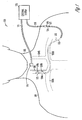
- FIG. 1 is an illustration of an embodiment of a neural stimulation system 100 and portions of an environment in which system 100 is used.
- System 100 includes an activity sensor 110 for sensing laryngeal activity, a transvenous lead 112 for delivering vagal nerve stimulation, and an external system 120 coupled to activity sensor 110 via a cable 111 and coupled to lead 112 via a cable 118.
- External system 120 allows for optimization of the vagal nerve stimulation using the sensed laryngeal activity.
- Lead 112 is a transvenous lead having a proximal end 114, a distal end 113, and an elongate body 115 coupled between proximal end 114 and distal end 113.
- Proximal end 114 includes a connector 117.
- distal end 113 includes stimulation electrodes 116A-B.
- a body 101 includes a neck 102, a right internal jugular vein 104A, a left internal jugular vein 104B, a right subclavian vein 105A, and a left subclavian vein 105B.
- Lead 112 is inserted using techniques similar to those employed in implanting cardiac pacing leads.
- distal end 113 enters the left subclavian vein 105B through an incision, advances in the subclavian veins 105B and then 105A toward right internal jugular vein 104A, enters right internal jugular vein 104A, advances in right internal jugular vein 104A until electrodes 116A-B reach one or more vagal nerve stimulation sites.
- stimulation electrodes 116A-B are positioned, and repositioned when necessary, using lead 112 and/or a lead insertion tool such as a stylet, a guide wire, or a guide catheter.
- Electrodes 116A-B allow neural stimulation to be delivered to a vagus nerve 106, which is adjacent to right internal jugular vein 104A in the cervical region.
- Activity sensor 110 is placed on the neck over the larynx to sense a signal indicative of laryngeal activity.
- the laryngeal activity is used as a measure of response of vagus nerve 106 to the neural stimulation delivered to vagus nerve 106.
- the laryngeal activity is monitored for placement of stimulation electrodes such as electrodes 116A-B, optimization of stimulation parameter such as those controlling stimulation intensity (e.g., stimulation amplitude, frequency, duration, and duty cycle), and detection or monitoring of various events that affect the response of vagal nerve 106 to the neural stimulation.
- proximal end 114 remains outside of body 101, such as during an operation of implantation of lead 112 and an implantable medical device such as one discussed below with reference to FIG. 2 .
- This allows electrodes 116A-B to be placed as desired before connecting proximal end 114 to the implantable medical device.
- Proximal end 114 includes a connector 117 coupled to a connector 119 of cable 118 to allow delivery of the neural stimulation from external system 120.
- External system 120 allows a user such as a physician or other caregiver to control the delivery of neural stimulation via lead 112 and monitor the signal indicative of larynx sensed by activity sensor 110.
- the configuration of system 100 shown in FIG. 1 is an example presented for illustrative purposes.
- the present subject matter generally includes monitoring and optimization of vagal nerve stimulation delivered using any electrode configuration using any signal that indicates laryngeal activity resulting from the vagal nerve stimulation.
- lead 112 may include one or more stimulation electrodes, and an electrode pair for delivering the neural stimulation may include two electrodes on lead 112 or an electrode on lead 112 and a reference electrode not necessarily adjacent to the vagus nerve.
- the reference electrode is a skin patch electrode for acute use.
- stimulation electrodes on lead 112 one or more nerve cuff electrodes each surrounding vagus nerve 106 are used.
- electrodes 116A-B are placed in the left interval jugular vein 104B.
- distal end 113 enters the left subclavian vein 105B or right subclavian vein 105A through an incision; enters left internal jugular vein 104B from right subclavian vein 105A, advances in left internal jugular vein 104B until electrodes 116A-B reach one or more vagal nerve stimulation sites.
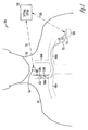
- FIG. 2 is an illustration of an embodiment of a neural stimulation system 200 and portions of the environment in which system 200 is used.
- System 200 differs from system 100 primarily in that the neural stimulation is delivered from an implantable medical device 222 implanted in body 101.
- FIGS. 1 and 2 illustrate different stages of implantation and use of an implantable neural stimulation system.
- FIG. 1 illustrates a system setup in the middle of an implantation procedure during which lead 112 is inserted with electrodes 116A-B placed to achieve desirable performance of vagal nerve stimulation.
- FIG. 1 illustrates a system setup in the middle of an implantation procedure during which lead 112 is inserted with electrodes 116A-B placed to achieve desirable performance of vagal nerve stimulation.
- FIG. 2 illustrates the system set-up after the implantable neural stimulation system is fully implanted, such as during the end stage of the implantation procedure when the implantable neural stimulation system is programmed for chronic use or during a follow-up examination during which the implantable neural stimulation system is adjusted if necessary.
- An activity sensor 210 represents an embodiment of activity sensor 110 that is capable of communicating with an external system 220 via a wireless link.
- activity sensor 110 and external system 220 are electrically connected using a cable, and a communication link 211 represents the cable.
- activity sensor 110 and external system 220 are wirelessly coupled through telemetry such as a radio-frequency electromagnetic telemetry link, and communication link 211 represents the telemetry link.
- Implantable medical device 222 delivers the neural stimulation through one or both of electrodes 116A-B. After electrodes 116A-B are placed, proximal end 114 of lead 112 is connected to implantable medical device 222 via connector 117.
- the housing of implantable medical device 222 functions as a reference electrode, and the neural stimulation can be delivered using any pair of electrodes selected from electrodes 116A-B and the housing of implantable medical device 222.
- neural activity in vagus nerve 106 is sensed using any pair of electrodes selected from electrodes 116A-B and the housing of implantable medical device 222.
- implantable medical device 222 in addition to the neural stimulation circuit, implantable medical device 222 includes other monitoring or therapeutic circuits or devices such as one or more of cardiac pacemaker, cardioverter/defibrillator, drug delivery device, and biological therapy device.
- External system 220 provides for control of and communication with implantable medical device 222 by the user.
- External system 220 and implantable medical device 222 are communicatively coupled via a telemetry link 218.
- external system 220 includes a programmer.
- external system 220 is a patient management system including an external device communicating with implantable medical device 222 via telemetry link 218, a remote device in a remote location, and a telecommunication network linking the external device and the remote device.
- telemetry link 218 is an inductive telemetry link. In an alternative embodiment, telemetry link 218 is a far-field radio-frequency telemetry link.
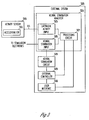
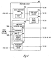
- FIG. 3 is a block diagram illustrating an embodiment of portions of a circuit of system 100, including an activity sensor 310 coupled to an external system 320 by cable 111.
- Activity sensor 310 is an embodiment of activity sensor 110 and includes an accelerometer 331 to sense an acceleration signal being the signal indicative of laryngeal activity.
- Accelerometer 331 has characteristics suitable for sensing the magnitude and frequency of vibrations of the larynx that indicate activity in the vagus nerve when vagal nerve stimulation is delivered.
- accelerometer 331 represents a plurality of accelerometers allowing for selection of an acceleration signal as the signal indicative of laryngeal activity based on the signal quality.
- External system 320 includes a neural stimulation analyzer 324, a neural stimulation circuit 328, an external controller 329, and a user interface 330.
- Neural stimulation analyzer 324 includes a laryngeal activity input 325, a neural stimulation input 326, and a processing circuit 327.
- Laryngeal activity input 325 receives the signal indicative of laryngeal activity from activity sensor 310 via cable 111.
- Neural stimulation input 326 receives a signal indicative of the delivery of the neural stimulation to the vagus nerve.
- Processing circuit 327 processes the signal indicative of laryngeal activity for analyzing the operation and performance of system 100 using that signal.
- Neural stimulation circuit 328 delivers the neural stimulation to stimulation electrodes such as electrodes 116A-B.
- External controller 329 controls overall operation of external system 320, including the delivery of the neural stimulation from neural stimulation circuit 328.
- User interface 330 allows the user to control the neural stimulation and monitor the response of the vagus nerve to the neural stimulation using the signal indicative of laryngeal activity.
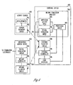
- FIG. 4 is a block diagram illustrating an embodiment of portion of a circuit of system 200, including an activity sensor 410 coupled to an external system 420 via communication link 211 and an implantable medical device 422 coupled to external system 420 via telemetry link 218.
- Activity sensor 410 is an embodiment of activity 210 and includes accelerometer 331 and a sensor telemetry circuit 432.
- communication link 211 is a telemetry link.
- Sensor telemetry circuit 432 transmits the sensed signal indicative of laryngeal activity to external system 420 via telemetry link 211.
- communication link 211 is a cable providing an electrical connection between accelerometer 331 and laryngeal activity input 325.
- External system 420 includes neural stimulation analyzer 324, external telemetry circuit 438, external controller 429, and user interface 330.
- External telemetry circuit 438 receives the signal indicative of laryngeal activity from activity sensor 410 via communication link 211 and communicates with implantable medical device 422 via telemetry link 218 to control the neural stimulation delivered from implantable medical device 422.
- External controller 429 controls overall operation of external system 420, including the transmission of commands for controlling the neural stimulation delivered from the implantable medical device 422.
- Implantable medical device 422 includes a neural stimulation circuit 434, an implant controller 435, and an implant telemetry circuit 436.
- Neural stimulation circuit 434 delivers the neural stimulation through stimulation electrodes such as electrodes 116A-B.
- Implant controller 435 controls the delivery of the neural stimulation and is responsive to the commands transmitted from external system 420.
- Implant telemetry circuit 436 receives the commands from external system 420 via telemetry link 218 and when needed, transmits signals to external system 420 via telemetry link 218.
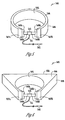
- FIG. 5 is an illustration of an embodiment of a laryngeal activity sensor assembly 540 that allows for a substantially stable attachment of an activity sensor on a patient's neck over the larynx.
- Laryngeal activity sensor assembly 540 includes an activity sensor 510 and a neck-bracing structure configured to hold activity sensor 510 on the neck over the larynx.
- Activity sensor 510 senses the signal indicative of laryngeal activity and represents any of activity sensors 110, 210, 310, and 410.
- a cable 511 is connected to activity sensor 510 and has a connector 542 to provide electrical connections between activity sensor 510 and external system 120 or 320.
- cable 511 is detachably coupled to activity sensor 510.
- activity sensor 510 is communicatively coupled to external system 220 or 420 via telemetry, and cable 511 is not needed.
- Laryngeal activity sensor assembly 540 includes a neck brace 544 that is configured to wrap around a substantial portion of the neck and limits the movement of the neck.
- Neck brace 544 includes two ends 547A-B that are separated by a substantial gap over an anterior portion of the neck.
- neck brace 544 is made of a material selected to limit the sensing of noise by activity sensor 510 by damping vibrations of environmental sources such as vibrations from equipment and activity of medical personnel.
- neck brace 544 is made of a substantially soft material such as foam.
- Neck brace 544 has an interior surface 545 and an exterior surface 546. Interior surface 545 is configured for contacting the neck.
- neck brace 544 has a substantially even thickness between interior surface 545 and exterior surface 546. This thickness is, for example, between approximately 10 mm and 80 mm.
- Laryngeal activity sensor assembly 540 further includes two brackets 548-B each affixed onto one of ends 547A-B. Straps 549A-B are coupled to brackets 548A-B and activity sensor 510. In one embodiment, straps 549A-B represent different portions of a single strap. In another embodiment, straps 549A-B represent two straps each coupled between activity sensor 510 and one of brackets 548A-B. Straps 549A-B are configured to press activity sensor 510 on the neck over the larynx for a substantially stable sensor placement. In one embodiment, straps 549A-B are stretchable elastic straps.
- At least one of straps 549A-B is releasably coupled to one of brackets 547A-B. In one embodiment, straps 549A-B are coupled to the brackets in a way allowing adjustment of a position of activity sensor 510 in cranial/caudal directions.
- neck brace 544 is shaped to fit over the patient's head and/or shoulders to further limit the relative movement between activity sensor 510 and the larynx.
- the edge of neck brace 544 that is toward the caudal direction when worn by a patient includes a contour that approximately fits over the patient's shoulders. This provides additional stability of sensor placement when the patient is sitting while the signal indicative of laryngeal activity is sensed.
- FIG. 6 is an illustration of an embodiment of a laryngeal activity sensor assembly 640, which is an alternative embodiment to laryngeal activity sensor assembly 540.
- Laryngeal activity sensor assembly 640 is similar to laryngeal activity sensor assembly 540 except for a neck brace 644, which is made of a material similar or identical to that of neck brace 544 but has a shape that is substantially different from that of neck brace 544.
- Neck brace 644 includes two ends 647A-B that are separated by a substantial gap over an anterior portion of the neck. Brackets 548A-B are each affixed to one of ends 647A-B.
- Neck brace 644 has an interior surface 645 and an exterior surface 646. Interior surface 644 is configured for contacting the neck. Exterior surface 646 is configured to increase stability of the sensor placement by further limiting movement of the neck. In one embodiment, as illustrated in FIG. 6 , exterior surface 646 has a flat back portion 650 over the posterior portion of the neck.
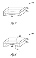
- FIG. 7 is an illustration of an embodiment of an activity sensor 710.
- Activity sensor 710 is an embodiment of activity sensor 510 that includes an accelerometer 731 affixed onto a sensor base 754.
- Accelerometer sensor 731 represents a specific embodiment of accelerometer 331 and senses the signal indicative of laryngeal activity.
- Sensor base 754 is configured to be an interface between accelerometer sensor 731 and the neck, and has a surface 755 curved to fit onto the neck.
- FIG. 8 is an illustration of an embodiment of an activity sensor 810.
- Activity sensor 810 is an embodiment of activity sensor 710 and includes accelerometer 731 and a sensor base 854.
- Sensor base 854 has a surface 855 curved to fit onto the neck of a male patient over part of his thyroid cartilage.
- surface 855 includes a recess 856 on one end and a notch 857 at the other end for fitting over part of the thyroid cartilage.
- FIG. 9 is a block diagram illustrating an embodiment of a processing circuit 927, which is a specific embodiment of processing circuit 327.
- Processing circuit 927 includes a signal conditioning circuit 960, a stimulation threshold analyzer 962, a lead status analyzer 966, a neural injury analyzer 968, and a presentation processing circuit 970.
- Signal conditioning circuit 960 conditions the signal indicative of laryngeal activity for analysis or presentation purposes.
- Signal conditioning circuit 960 increases the signal-to-noise ratio of the signal indicative of laryngeal activity, where the signal includes components of the signal indicative of laryngeal activity that result from the vagal nerve stimulation, and the noise includes components of the signal indicative of laryngeal activity that is not an effect of the vagal nerve stimulation.
- Signal conditioning circuit 960 includes a filter 961 that filters out the noise. In one embodiment, filter 961 has a passband selected based on the frequency at which neural stimulation pulses are delivered to the vagus nerve.
- Stimulation threshold analyzer 962 automatically measures a stimulation threshold associated with each pair of stimulation electrodes via which the neural stimulation is delivered to the vagus nerve, such as stimulation electrodes 116A-B.
- the stimulation threshold is the minimum stimulation intensity at which the neural stimulation activates the vagus nerve.
- Stimulation threshold analyzer 962 includes a comparator 963 and a stimulation intensity controller 964.
- Comparator 963 includes a first input 963A to receive an amplitude of the signal indicative of laryngeal activity, a second input 963B to receive a nerve capture threshold, and an output 963C that indicates a nerve capture when the amplitude of the signal indicative of laryngeal activity exceeds the nerve capture threshold.
- an amplitude of the signal indicative of laryngeal activity that exceeds the nerve capture threshold is the indication that the neural stimulation has elicited action potentials propagating in the vagus nerve.
- the nerve capture threshold is determined empirically based a patient population or each individual patient.
- Stimulation intensity controller 964 adjusts the stimulation intensity of the neural stimulation such that a plurality of stimulation intensities may be tested, and stimulation threshold analyzer 962 automatically determines the stimulation threshold by selecting the tested minimum stimulation intensity that results in a nerve capture.
- the stimulation intensity is controlled by stimulation amplitude (voltage or current) and/or stimulation pulse width.
- Stimulation intensity controller 964 adjusts the stimulation intensity by adjusting the stimulation amplitude, the stimulation pulse width, or both. In one embodiment, stimulation intensity controller 964 increases the stimulation intensity from an initial intensity until the nerve capture is indicated or a specified maximum stimulation intensity is reached. If the maximum stimulation intensity is reached before the nerve capture is indicated, the stimulation electrodes are repositioned before the determination of the stimulation threshold continues. In one embodiment, stimulation threshold analyzer 962 presents the minimum capture intensity at which the nerve capture is indicated when the stimulation intensity is being increased as the stimulation threshold. In another embodiment, after the minimum capture intensity is reached, stimulation intensity controller 964 decreases the stimulation intensity from that minimum capture intensity until the nerve capture is no longer indicated. Stimulation threshold analyzer 962 presents the minimum stimulation intensity at which the nerve capture is indicated when the stimulation intensity is being decreased as the stimulation threshold.
- Lead status analyzer 966 detects dislodgment or breakage of a lead for delivering the neural stimulation, such as lead 112, by detecting a substantial change in the stimulation threshold between two stimulation threshold measurements. In one embodiment, upon detection of the dislodgment or breakage of the lead, lead status analyzer 966 produces a warning signal or message to be presented to the user through user interface 330.
- Neural injury analyzer 968 detects a nerve injury by monitoring the change in the stimulation threshold and/or the change in the amplitude of the signal indicative of laryngeal activity over time.
- the laryngeal nerves include efferent nerve fibers.
- a neural injury occurring in the nervous path between the stimulation site and the larynx is indicated by absence or weakening of laryngeal response to the vagal nerve stimulation.
- a weakened laryngeal response may serve as an early indication of the neural injury. Appropriate treatments may be applied in response, thereby preventing the neural injury from progressing to a degree associated with a major functional impairment.
- neural injury analyzer 968 monitors the change in the stimulation threshold over time, determines the speed of the change in the stimulation threshold, and detects a neural injury based on the speed of the change in the stimulation threshold. In another embodiment, neural injury analyzer 968 monitors the amplitude of the signal indicative of laryngeal activity in response to delivering the neural stimulation at a specified stimulation intensity over time, determines the speed of the change in the amplitude of the signal indicative of laryngeal activity, and detects a neural injury based on the speed of the change in the amplitude of the signal indicative of laryngeal activity. In another embodiment, neural injury analyzer 968 detects a substantial change in neural conduction velocity as an indication of neural injury.
- neural injury analyzer 968 measures the neural conduction velocity as the ratio of a neural conduction time to an estimated neural conduction distance, and detects a neural injury based on the change in the neural conduction velocity over time.
- the neural conduction time is the time interval between the delivery of a stimulus and the beginning of the elicited response in the signal indicative of laryngeal activity.
- neural injury analyzer 968 measures the neural conduction time being the time interval between the delivery of a stimulus and the beginning of the elicited response in the signal indicative of laryngeal activity, and detects a neural injury based on the change in the neural conduction time over time.
- neural injury analyzer 968 upon detection of a possible neural injury, produces a warning signal or message to be presented to the user through user interface 330.
- Presentation processing circuit 970 processes the signal indicative of laryngeal activity for presentation to the user in one or more forms through user interface 330. In one embodiment, presentation processing circuit 970 also processes other signals, messages, and/or indicators related to laryngeal activity, lead status, neural injury, and/or other related information for presentation to the user through user interface 330.
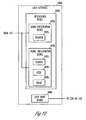
- FIG. 10 is a block diagram illustrating an embodiment of a user interface 1030.
- User interface 1030 is a specific embodiment of user interface 330 and includes a presentation device 1072 and a user input device 1080.
- Presentation device 1072 presents indicators of the laryngeal activity and the neural stimulation in one or more forms.
- User input device 1080 allows the user to control the neural stimulation by entering commands and parameters, and to control presentation device 1080 by choosing how the laryngeal activity and the neural stimulation are indicated.
- presentation device 1072 includes an audio presentation device 1074 and a visual presentation device 1076.
- Audio presentation device 1074 includes a speaker 1075 that generates an audible tone indicative of the laryngeal activity.
- the audible tone has a pitch indicative a frequency at which the larynx vibrates and/or a magnitude of the laryngeal activity.
- the audible tone has a pitch indicative the frequency at which the larynx vibrates and a volume indicative of the magnitude of the laryngeal activity.
- the stimulation frequency the frequency at which the electrical pulses are delivered
- the muscular response in the larynx may change from a twitch response to a tentatic response (which means the muscle stays contracted during the delivery of an entire pulse train).
- the stimulation frequency is selected such that the delivery of the electrical pulses elicits a twitch response but not a tentatic response.
- the frequency at which the larynx vibrates is the stimulation frequency
- the magnitude of the laryngeal activity is a function of the stimulation intensity.
- Visual presentation device 1076 includes a screen 1077, light-emitting diodes (LEDs) 1078, and a gauge 1079.
- Screen 1077 displays the signal indicative of laryngeal activity and a signal indicative of the neural stimulation. Examples of the signal indicative of the neural stimulation include neural stimulation markers and a neural signal indicative of vagal nerve activity sensed by the stimulation electrodes such as electrodes 116A-B.
- screen 1077 further displays one or more sensed physiological signals such as electrocardiogram (ECG) and various signals, messages, and/or indicators related to laryngeal activity, lead status, neural injury, and/or other related information.
- LEDs 1078 are each turned on when the amplitude of the signal indicative of laryngeal activity exceeds a predetermined threshold.
- a plurality of different thresholds each associated with one or more of LEDs 1078 allows for selective lighting of each of LEDs 1078 according to the amplitude of the signal indicative of laryngeal activity.
- Gauge 1079 indicates the magnitude of the laryngeal activity.
- gauge 1079 is in the form of an image displayed in screen 1077. In another embodiment, gauge 1079 is a device separated from screen 1077.
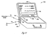
- FIG. 11 is an illustration of an external programmer 1120, which is an embodiment of external system 120, 220, 320, or 420.
- external programmer 1120 includes speaker 1075, screen 1077, LEDs 1078, and gauge 1079.
- external programmer 1120 includes any one or more of speaker 1075, screen 1077, LEDs 1078, and gauge 1079.
- screen 1077 includes a trace of the signal indicative of laryngeal activity, a signal indicative of the neural stimulation, a trace and an ECG signal, and an area 1182 displaying the various signals, messages, and/or indicators related to laryngeal activity, lead status, neural injury, and/or other related information.
- Programmer 1120 receives the signal indicative of laryngeal activity and controls the neural stimulation by allowing the user to enter commands and parameters.
- programmer 1120 includes a sensor input 1184 and a stimulation output 1185.
- Activity sensor 510 senses the signal indicative of laryngeal activity and transmits the sensed signal to programmer 1120 through cable 511 and connector 542, which is detachably connected to sensor input 1184.
- Cable 118 with a connector 1187 detachably connected to stimulation output 1185 and connector 119 provides for connection to stimulation electrodes such as stimulation electrodes 116A-B on lead 112. This allows for delivery of the neural stimulation from a neural stimulation circuit of programmer 1120.
- programmer 1120 is also capable of receiving the signal indicative of laryngeal activity from activity sensor 510 via telemetry. In one embodiment, programmer 1120 is also capable of controlling the delivery of the neural stimulation from a neural stimulation circuit of an implantable medical device via telemetry.
- FIG. 12 is a flow chart illustrating an embodiment of a method 1200, which does not not form part of the invention, for analyzing effect of neural stimulation using a signal indicative of laryngeal activity.
- method 1200 is performed by systems 100 or 200.
- the signal indicative of laryngeal activity is sensed at 1210.
- the neural stimulation is delivered to the vagus nerve at 1220.
- the signal indicative of laryngeal activity is conditioned at 1230, to isolate laryngeal activity resulting from the delivery of the neural stimulation from other components of the sensed signal indicative of laryngeal activity.
- An effect of the delivery of the neural stimulation is analyzed at 1240 using the signal indicative of laryngeal activity.
- Indicators of the laryngeal activity and the delivery of the neural stimulation are presented at 1250.
- an audible tone indicative of the laryngeal activity is generated.
- the audible tone has a pitch indicative a magnitude of the laryngeal activity.
- the audible tone has a pitch indicative a frequency at which the larynx vibrates and a volume indicative of a magnitude of the laryngeal activity.
- a visual indication of the laryngeal activity is produced. Examples of the visual indication include traces of the signal indicative of laryngeal activity, a signal indicative of the neural stimulation, and a gauge indicative of magnitude of the laryngeal activity.
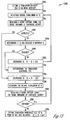
- FIG. 13 is a flow chart illustrating an embodiment of a method 1300, which does not form part of the invention, for automatically determining a stimulation threshold for the neural stimulation using the signal indicative of laryngeal activity.
- the stimulation threshold is indicative of the minimum stimulation intensity required to capture the vagus nerve.
- method 1300 is performed by stimulation threshold analyzer 962.
- the stimulation intensity (SI) of the neural stimulation is set to an initial intensity at 1310.
- the initial intensity is an empirically determined parameter.
- the initial intensity is selected by the user.
- the SI is controlled by the (voltage or current) and the pulse width of each of the electrical pulses.
- the neural stimulation is delivered to the vagus nerve at the SI at 1312.
- a nerve capture is being detected using the signal indicative of laryngeal activity at 1314, by comparing the amplitude of the signal indicative of laryngeal activity to a nerve capture threshold.
- the nerve capture is detected at 1316 if the amplitude of the signal indicative of laryngeal activity exceeds the nerve capture threshold.
- the stimulation electrodes are repositioned, or other approaches must be taken to increase the specified maximum SI and/or decease the stimulation threshold, at 1324.
- the stimulation electrodes are "repositioned", or selected, electronically.
- the neural stimulation is delivered to the vagus nerve using an active set of stimulation electrodes electronically selected from multiple available sets of stimulation electrodes, and electronically repositioning means electronically selecting a different set of available stimulation electrodes to be the active set of stimulation electrodes. If the SI has not reached the specified maximum SI at 1320, the SI is increased by ⁇ SI at 1322, and method 1300 returns to 1312 to continue therefrom.
- the stimulation threshold is determined as a voltage of an electrical pulse at a specified pulse width. In a specific embodiment, ⁇ SI is about 0.2 V.
- the current SI is the minimum capture intensity at which the nerve capture is detected as the stimulation intensity is being increased.
- the SI is decreased from that minimum capture intensity, with ⁇ SI' being the decrement step, at 1326.
- ⁇ SI' and ⁇ SI are set to the same value.
- ⁇ SI' is about 0.2 V.
- the neural stimulation is delivered at the (decreased) SI at 1328.
- a nerve capture is being detected using the signal indicative of laryngeal activity at 1330, by comparing the amplitude of the signal indicative of laryngeal activity to the nerve capture threshold.
- the nerve capture is detected at 1332 if the amplitude of the signal indicative of laryngeal activity exceeds the nerve capture threshold.
- method 1300 returns to 1326 to further decrease the SI and continue therefrom. If the nerve capture is not detected at 1332, the SI prior to the last decrease at 1326 is set to the stimulation threshold at 1334. That is, the stimulation threshold (ST) is the current SI (after 1326) plus ⁇ SI'.
- FIG. 14 is a flow chart illustrating an embodiment of a method 1400, which does not form part of the invention, for monitoring and titrating the neural stimulation acutely and chronically using the signal indicative of laryngeal activity.
- Method 1400 is performed during and after the implantation of an implantable neural stimulation system. In one embodiment, method 1400 is performed with systems 100 and/or 200.
- the signal indicative of laryngeal activity is sensed at 1410.
- the neural stimulation is delivered to the vagus nerve at 1420.
- the laryngeal activity indicates the response of the vagus nerve to the neural stimulation.
- the response depends on, for example, the position of the stimulation electrodes, stimulation parameters, condition of the neural stimulation system such as condition of the leads and/or stimulation electrodes, existence and progress of neural injury, and healing of tissue surrounding the stimulation electrodes following implantation of the stimulation electrodes.
- the delivery of the neural stimulation is optimized during the implantation of an implantable medical device at 1430. This includes, for example, positioning a stimulation electrode at 1432 and optimizing stimulation parameters associated with that stimulation electrode at 1434. In various embodiments, 1432 and 1434 are performed for each stimulation electrode or each pair of stimulation electrodes.
- the stimulation electrode is placed for delivering the neural stimulation to the vagus nerve using the signal indicative of laryngeal activity. In one embodiment, the stimulation electrode is incorporated onto the distal end of a transvenous lead. The transvenous lead is inserted into the vascular system such that the stimulation electrode is in a position within an approximate target region in an internal jugular vein.
- a stimulation threshold is determined automatically, such as by performing method 1300, for that position using the signal indicative of laryngeal activity. If the stimulation threshold is not satisfactory, the stimulation electrode is placed in another position within the approximate target region, and the stimulation threshold is determined for the new position. The repositioning and threshold determination are repeated until a satisfactory stimulation threshold is obtained. In one embodiment, the repositioning is performed electronically.
- the neural stimulation is delivered using an active stimulation electrode electronically selected from a plurality of available stimulation electrodes, and placing a stimulation electrode in another position means electronically selecting an available stimulation electrode placed in another position to be the active stimulation electrode.
- a minimal electrical current is delivered to the vagus nerve using the stimulation electrode.
- the amplitude is kept low but sufficient to produce laryngeal activity that can be sensed.
- the amplitude of the signal indicative of laryngeal activity is monitored while the stimulation electrode is moved to evaluate positions within the approximate target region.
- the stimulation electrode is positioned permanently in the location associated with a maximum amplitude of the signal indicative of laryngeal activity.
- the stimulation parameters associated with the stimulation electrode are optimized at 1434. In one embodiment, this includes determining the stimulation threshold associated with the stimulation electrode automatically, such as by performing method 1300, for the permanent position of the stimulation electrode.
- the stimulation intensity associated with the stimulation electrode is programmed for chronic use based on the stimulation threshold, such as by setting the stimulation intensity to a value exceeding the stimulation threshold by a predetermined margin.
- the delivery of the neural stimulation is monitored and titrated after the device implantation at 1440. This includes, for example, optimizing stimulation parameters at 1442, monitoring a lead or stimulation electrode status at 1444, detecting a neural injury at 1446, and monitoring a healing process at 1448.
- 1440, or any portion thereof is performed by the user during a follow-up examination according a specified schedule, such as on an approximately periodic basis.
- the stimulation parameters are optimized at 1442. In one embodiment, this includes determining the stimulation threshold associated with each stimulation electrode automatically, such as by performing method 1300. If the stimulation threshold associated with an electrode has changed substantially from the previous measurement, the stimulation intensity associated with that stimulation electrode is adjusted based on the new stimulation threshold, such as by setting the stimulation intensity to a value exceeding the new stimulation threshold by a predetermined margin.
- the lead or stimulation electrode status is monitored at 1444. This includes, for example, detection of possible displacement, dislodgement, and breakage of the lead. A possible lead problem is indicated by a substantial, abnormal change in the stimulation threshold between measurements of the stimulation threshold.
- a neural injury is detected at 1446.
- the neural injury is detected by monitoring the change in the stimulation threshold over time.
- a possible neural injury is indicated by a detected abnormal speed of change in the stimulation threshold.
- the neural injury is detected by monitoring the amplitude of the signal indicative of laryngeal activity in response to delivering neural stimulation at a specified stimulation intensity over time.
- a possible neural injury is indicated by a detected abnormal speed of the change in the amplitude of the signal indicative of laryngeal activity.
- the neural injury detection at 1446 allows for early discovery of a neural injury that needs immediate treatment to prevent from developing into a major functional impairment.
- a healing process is monitored at 1448. After the implantation of the implantable medical device and the lead or stimulation electrodes, it may take weeks or months for the tissue injured during the implantation to heal and the interface between the body and the implanted system to stabilize. This healing process is monitored by monitoring the change in the stimulation threshold over time.
- a stabilized stimulation threshold is an indication that the healing process may have substantially completed.
Landscapes
- Health & Medical Sciences (AREA)
- Life Sciences & Earth Sciences (AREA)
- Engineering & Computer Science (AREA)
- General Health & Medical Sciences (AREA)
- Biomedical Technology (AREA)
- Veterinary Medicine (AREA)
- Public Health (AREA)
- Animal Behavior & Ethology (AREA)
- Medical Informatics (AREA)
- Heart & Thoracic Surgery (AREA)
- Physics & Mathematics (AREA)
- Molecular Biology (AREA)
- Surgery (AREA)
- Pathology (AREA)
- Biophysics (AREA)
- Neurosurgery (AREA)
- Neurology (AREA)
- Signal Processing (AREA)
- Physiology (AREA)
- Medicinal Chemistry (AREA)
- Bioinformatics & Cheminformatics (AREA)
- Dentistry (AREA)
- Oral & Maxillofacial Surgery (AREA)
- Chemical & Material Sciences (AREA)
- Artificial Intelligence (AREA)
- Computer Vision & Pattern Recognition (AREA)
- Psychiatry (AREA)
- Nuclear Medicine, Radiotherapy & Molecular Imaging (AREA)
- Radiology & Medical Imaging (AREA)
- Electrotherapy Devices (AREA)
Applications Claiming Priority (2)
| Application Number | Priority Date | Filing Date | Title |
|---|---|---|---|
| US11/469,551 US7801603B2 (en) | 2006-09-01 | 2006-09-01 | Method and apparatus for optimizing vagal nerve stimulation using laryngeal activity |
| PCT/US2007/018696 WO2008030348A1 (en) | 2006-09-01 | 2007-08-24 | Neural stimulation system with laryngeal activity sensor |
Publications (2)
| Publication Number | Publication Date |
|---|---|
| EP2077894A1 EP2077894A1 (en) | 2009-07-15 |
| EP2077894B1 true EP2077894B1 (en) | 2011-05-11 |
Family
ID=38814470
Family Applications (1)
| Application Number | Title | Priority Date | Filing Date |
|---|---|---|---|
| EP07837286A Not-in-force EP2077894B1 (en) | 2006-09-01 | 2007-08-24 | Neural stimulation system with laryngeal activity sensor |
Country Status (8)
| Country | Link |
|---|---|
| US (2) | US7801603B2 (enExample) |
| EP (1) | EP2077894B1 (enExample) |
| JP (1) | JP5215309B2 (enExample) |
| CN (1) | CN101528302B (enExample) |
| AT (1) | ATE508766T1 (enExample) |
| AU (1) | AU2007293449B2 (enExample) |
| ES (1) | ES2366416T3 (enExample) |
| WO (1) | WO2008030348A1 (enExample) |
Families Citing this family (135)
| Publication number | Priority date | Publication date | Assignee | Title |
|---|---|---|---|---|
| US20100331883A1 (en) | 2004-10-15 | 2010-12-30 | Schmitz Gregory P | Access and tissue modification systems and methods |
| US9247952B2 (en) | 2004-10-15 | 2016-02-02 | Amendia, Inc. | Devices and methods for tissue access |
| US8617163B2 (en) | 2004-10-15 | 2013-12-31 | Baxano Surgical, Inc. | Methods, systems and devices for carpal tunnel release |
| US20110190772A1 (en) | 2004-10-15 | 2011-08-04 | Vahid Saadat | Powered tissue modification devices and methods |
| US8257356B2 (en) | 2004-10-15 | 2012-09-04 | Baxano, Inc. | Guidewire exchange systems to treat spinal stenosis |
| US8062300B2 (en) | 2006-05-04 | 2011-11-22 | Baxano, Inc. | Tissue removal with at least partially flexible devices |
| US8430881B2 (en) * | 2004-10-15 | 2013-04-30 | Baxano, Inc. | Mechanical tissue modification devices and methods |
| US20090171381A1 (en) * | 2007-12-28 | 2009-07-02 | Schmitz Gregory P | Devices, methods and systems for neural localization |
| US9101386B2 (en) | 2004-10-15 | 2015-08-11 | Amendia, Inc. | Devices and methods for treating tissue |
| US8221397B2 (en) | 2004-10-15 | 2012-07-17 | Baxano, Inc. | Devices and methods for tissue modification |
| US8048080B2 (en) * | 2004-10-15 | 2011-11-01 | Baxano, Inc. | Flexible tissue rasp |
| US7578819B2 (en) | 2005-05-16 | 2009-08-25 | Baxano, Inc. | Spinal access and neural localization |
| AU2005295589B2 (en) | 2004-10-15 | 2009-12-03 | Baxano, Inc. | Devices and methods for tissue removal |
| US7857813B2 (en) | 2006-08-29 | 2010-12-28 | Baxano, Inc. | Tissue access guidewire system and method |
| US7959577B2 (en) * | 2007-09-06 | 2011-06-14 | Baxano, Inc. | Method, system, and apparatus for neural localization |
| US8092456B2 (en) | 2005-10-15 | 2012-01-10 | Baxano, Inc. | Multiple pathways for spinal nerve root decompression from a single access point |
| US8062298B2 (en) | 2005-10-15 | 2011-11-22 | Baxano, Inc. | Flexible tissue removal devices and methods |
| US8366712B2 (en) | 2005-10-15 | 2013-02-05 | Baxano, Inc. | Multiple pathways for spinal nerve root decompression from a single access point |
| US9610459B2 (en) | 2009-07-24 | 2017-04-04 | Emkinetics, Inc. | Cooling systems and methods for conductive coils |
| US9339641B2 (en) | 2006-01-17 | 2016-05-17 | Emkinetics, Inc. | Method and apparatus for transdermal stimulation over the palmar and plantar surfaces |
| US20100168501A1 (en) * | 2006-10-02 | 2010-07-01 | Daniel Rogers Burnett | Method and apparatus for magnetic induction therapy |
| US7801603B2 (en) * | 2006-09-01 | 2010-09-21 | Cardiac Pacemakers, Inc. | Method and apparatus for optimizing vagal nerve stimulation using laryngeal activity |
| US9005102B2 (en) | 2006-10-02 | 2015-04-14 | Emkinetics, Inc. | Method and apparatus for electrical stimulation therapy |
| US10786669B2 (en) | 2006-10-02 | 2020-09-29 | Emkinetics, Inc. | Method and apparatus for transdermal stimulation over the palmar and plantar surfaces |
| US11224742B2 (en) | 2006-10-02 | 2022-01-18 | Emkinetics, Inc. | Methods and devices for performing electrical stimulation to treat various conditions |
| US9089707B2 (en) * | 2008-07-02 | 2015-07-28 | The Board Of Regents, The University Of Texas System | Systems, methods and devices for paired plasticity |
| US8192436B2 (en) | 2007-12-07 | 2012-06-05 | Baxano, Inc. | Tissue modification devices |
| US8382667B2 (en) | 2010-10-01 | 2013-02-26 | Flint Hills Scientific, Llc | Detecting, quantifying, and/or classifying seizures using multimodal data |
| US8337404B2 (en) | 2010-10-01 | 2012-12-25 | Flint Hills Scientific, Llc | Detecting, quantifying, and/or classifying seizures using multimodal data |
| US8571643B2 (en) | 2010-09-16 | 2013-10-29 | Flint Hills Scientific, Llc | Detecting or validating a detection of a state change from a template of heart rate derivative shape or heart beat wave complex |
| US9549704B1 (en) * | 2008-03-28 | 2017-01-24 | Sandia Corporation | Neural interface methods and apparatus to provide artificial sensory capabilities to a subject |
| US8398641B2 (en) | 2008-07-01 | 2013-03-19 | Baxano, Inc. | Tissue modification devices and methods |
| US8409206B2 (en) * | 2008-07-01 | 2013-04-02 | Baxano, Inc. | Tissue modification devices and methods |
| US9314253B2 (en) | 2008-07-01 | 2016-04-19 | Amendia, Inc. | Tissue modification devices and methods |
| WO2010009093A2 (en) | 2008-07-14 | 2010-01-21 | Baxano, Inc | Tissue modification devices |
| JP5427233B2 (ja) | 2008-07-08 | 2014-02-26 | カーディアック ペースメイカーズ, インコーポレイテッド | 迷走神経刺激を送達する医療システム |
| WO2010051500A1 (en) * | 2008-10-31 | 2010-05-06 | Medtronic, Inc. | Therapy system including cardiac rhythm therapy and neurostimulation capabilities |
| WO2010054116A1 (en) * | 2008-11-10 | 2010-05-14 | Cardiac Pacemakers, Inc. | Distal end converter for a medical device lead |
| US9370654B2 (en) | 2009-01-27 | 2016-06-21 | Medtronic, Inc. | High frequency stimulation to block laryngeal stimulation during vagal nerve stimulation |
| EP2405823A4 (en) | 2009-03-13 | 2012-07-04 | Baxano Inc | DEVICES AND METHODS FOR FLEXIBLE NERVOUSING |
| WO2010138228A1 (en) * | 2009-05-26 | 2010-12-02 | Cardiac Pacemakers, Inc. | Helically formed coil for a neural cuff electrode |
| US8394102B2 (en) | 2009-06-25 | 2013-03-12 | Baxano, Inc. | Surgical tools for treatment of spinal stenosis |
| US8588906B2 (en) * | 2009-07-15 | 2013-11-19 | Cardiac Pacemakers, Inc. | Physiological vibration detection in an implanted medical device |
| US8301241B2 (en) | 2009-07-15 | 2012-10-30 | Cardiac Pacemakers, Inc. | Remote pace detection in an implantable medical device |
| AU2010273544B2 (en) | 2009-07-15 | 2013-05-02 | Cardiac Pacemakers, Inc. | Remote sensing in an implantable medical device |
| JP2013508119A (ja) | 2009-10-26 | 2013-03-07 | エムキネティクス, インコーポレイテッド | 神経、筋肉および身体組織の電磁刺激のための方法および装置 |
| US8914115B2 (en) * | 2009-12-03 | 2014-12-16 | Medtronic, Inc. | Selecting therapy cycle parameters based on monitored brain signal |
| JP5624672B2 (ja) | 2010-04-15 | 2014-11-12 | カーディアック ペースメイカーズ, インコーポレイテッド | 断続的神経刺激による過渡反応を使用する自律神経調節 |
| US8639327B2 (en) | 2010-04-29 | 2014-01-28 | Medtronic, Inc. | Nerve signal differentiation in cardiac therapy |
| US8562536B2 (en) | 2010-04-29 | 2013-10-22 | Flint Hills Scientific, Llc | Algorithm for detecting a seizure from cardiac data |
| US8831732B2 (en) | 2010-04-29 | 2014-09-09 | Cyberonics, Inc. | Method, apparatus and system for validating and quantifying cardiac beat data quality |
| US8649871B2 (en) | 2010-04-29 | 2014-02-11 | Cyberonics, Inc. | Validity test adaptive constraint modification for cardiac data used for detection of state changes |
| US8406868B2 (en) | 2010-04-29 | 2013-03-26 | Medtronic, Inc. | Therapy using perturbation and effect of physiological systems |
| WO2011153027A1 (en) * | 2010-06-03 | 2011-12-08 | Cardiac Pacemakers, Inc. | System for controlling target of neurostimulation using temporal parameters |
| US8509919B2 (en) * | 2010-06-03 | 2013-08-13 | Cardiac Pacemakers, Inc. | Spatially selective vagus nerve stimulation |
| WO2011159545A2 (en) | 2010-06-18 | 2011-12-22 | Cardiac Pacemakers, Inc. | Neurostimulation system with control using evoked responses |
| WO2012012432A1 (en) | 2010-07-19 | 2012-01-26 | Cardiac Pacemakers, Inc. | Minimally invasive lead system for vagus nerve stimulation |
| US8641646B2 (en) | 2010-07-30 | 2014-02-04 | Cyberonics, Inc. | Seizure detection using coordinate data |
| US20120041773A1 (en) * | 2010-08-12 | 2012-02-16 | Patrik Kunz | Computerized system for adaptive radiation therapy |
| EP3002037B1 (en) | 2010-09-15 | 2018-06-06 | Cardiac Pacemakers, Inc. | Automatic selection of lead configuration for a neural stimulation lead |
| US12383190B2 (en) | 2011-03-04 | 2025-08-12 | Flint Hills Scientific, Llc | Detecting, assessing and managing extreme seizure events |
| US8684921B2 (en) | 2010-10-01 | 2014-04-01 | Flint Hills Scientific Llc | Detecting, assessing and managing epilepsy using a multi-variate, metric-based classification analysis |
| US9393415B2 (en) * | 2010-12-29 | 2016-07-19 | Cardiac Pacemakers, Inc. | Systems and methods for using electrical impedance for neuro cardiac therapy |
| US9393417B2 (en) * | 2010-12-29 | 2016-07-19 | Cardiac Pacemakers, Inc. | Systems and methods for using sensed pressure for neuro cardiac therapy |
| US8725259B2 (en) * | 2011-01-19 | 2014-05-13 | Medtronic, Inc. | Vagal stimulation |
| US8706223B2 (en) | 2011-01-19 | 2014-04-22 | Medtronic, Inc. | Preventative vagal stimulation |
| US8718763B2 (en) | 2011-01-19 | 2014-05-06 | Medtronic, Inc. | Vagal stimulation |
| US8781582B2 (en) | 2011-01-19 | 2014-07-15 | Medtronic, Inc. | Vagal stimulation |
| WO2012103224A1 (en) | 2011-01-25 | 2012-08-02 | Medtronic, Inc. | Target therapy delivery site selection |
| US9504390B2 (en) | 2011-03-04 | 2016-11-29 | Globalfoundries Inc. | Detecting, assessing and managing a risk of death in epilepsy |
| US9498162B2 (en) | 2011-04-25 | 2016-11-22 | Cyberonics, Inc. | Identifying seizures using heart data from two or more windows |
| US9402550B2 (en) | 2011-04-29 | 2016-08-02 | Cybertronics, Inc. | Dynamic heart rate threshold for neurological event detection |
| US9026214B2 (en) | 2011-06-23 | 2015-05-05 | Cardiac Pacemakers, Inc. | Systems and methods for avoiding aspiration during autonomic modulation therapy |
| WO2013003278A1 (en) | 2011-06-28 | 2013-01-03 | Cardiac Pacemakers, Inc. | Strain relief feature for an implantable medical device lead |
| JP2014521400A (ja) | 2011-07-07 | 2014-08-28 | カーディアック ペースメイカーズ, インコーポレイテッド | 植え込み型医療装置リード用の絶縁および安定機構 |
| JP5849158B2 (ja) * | 2011-08-23 | 2016-01-27 | カーディアック ペースメイカーズ, インコーポレイテッド | 迷走神経の捕捉を検出するシステムおよび方法 |
| EP2564897A1 (en) * | 2011-08-31 | 2013-03-06 | St. Jude Medical AB | System for determining pacing settings |
| US10206591B2 (en) | 2011-10-14 | 2019-02-19 | Flint Hills Scientific, Llc | Seizure detection methods, apparatus, and systems using an autoregression algorithm |
| US8600505B2 (en) | 2011-12-07 | 2013-12-03 | Cyberonics, Inc. | Implantable device for facilitating control of electrical stimulation of cervical vagus nerves for treatment of chronic cardiac dysfunction |
| US8918190B2 (en) | 2011-12-07 | 2014-12-23 | Cyberonics, Inc. | Implantable device for evaluating autonomic cardiovascular drive in a patient suffering from chronic cardiac dysfunction |
| US8918191B2 (en) | 2011-12-07 | 2014-12-23 | Cyberonics, Inc. | Implantable device for providing electrical stimulation of cervical vagus nerves for treatment of chronic cardiac dysfunction with bounded titration |
| US8630709B2 (en) | 2011-12-07 | 2014-01-14 | Cyberonics, Inc. | Computer-implemented system and method for selecting therapy profiles of electrical stimulation of cervical vagus nerves for treatment of chronic cardiac dysfunction |
| US10188856B1 (en) | 2011-12-07 | 2019-01-29 | Cyberonics, Inc. | Implantable device for providing electrical stimulation of cervical vagus nerves for treatment of chronic cardiac dysfunction |
| US9345885B2 (en) * | 2011-12-07 | 2016-05-24 | Med-El Elektromedizinische Geraete Gmbh | Pacemaker for unilateral vocal cord autoparalysis |
| US8577458B1 (en) | 2011-12-07 | 2013-11-05 | Cyberonics, Inc. | Implantable device for providing electrical stimulation of cervical vagus nerves for treatment of chronic cardiac dysfunction with leadless heart rate monitoring |
| AU2012347510B2 (en) * | 2011-12-07 | 2015-09-17 | Med-El Elektromedizinische Geraete Gmbh | Stimulation system and method for voice lift |
| US9731131B2 (en) | 2011-12-07 | 2017-08-15 | Med-El Elektromedizinische Geraete Gmbh | Pacemaker for unilateral vocal cord autoparalysis |
| US20130165994A1 (en) * | 2011-12-27 | 2013-06-27 | David J. Ternes | Maintaining stimulation therapy efficacy |
| US8700150B2 (en) | 2012-01-17 | 2014-04-15 | Cyberonics, Inc. | Implantable neurostimulator for providing electrical stimulation of cervical vagus nerves for treatment of chronic cardiac dysfunction with bounded titration |
| US8571654B2 (en) | 2012-01-17 | 2013-10-29 | Cyberonics, Inc. | Vagus nerve neurostimulator with multiple patient-selectable modes for treating chronic cardiac dysfunction |
| AU2013230648B2 (en) * | 2012-03-05 | 2017-06-15 | Lungpacer Medical Inc. | Transvascular nerve stimulation apparatus and methods |
| US9855431B2 (en) * | 2012-03-19 | 2018-01-02 | Cardiac Pacemakers, Inc. | Systems and methods for monitoring for nerve damage |
| US8903509B2 (en) | 2012-03-21 | 2014-12-02 | Cardiac Pacemakers Inc. | Systems and methods for stimulation of vagus nerve |
| US10448839B2 (en) | 2012-04-23 | 2019-10-22 | Livanova Usa, Inc. | Methods, systems and apparatuses for detecting increased risk of sudden death |
| US9681836B2 (en) | 2012-04-23 | 2017-06-20 | Cyberonics, Inc. | Methods, systems and apparatuses for detecting seizure and non-seizure states |
| US8688212B2 (en) | 2012-07-20 | 2014-04-01 | Cyberonics, Inc. | Implantable neurostimulator-implemented method for managing bradycardia through vagus nerve stimulation |
| US9283379B2 (en) | 2012-10-02 | 2016-03-15 | Cardiac Pacemakers, Inc. | Pinch to open cuff electrode |
| EP2903686B1 (en) | 2012-10-02 | 2018-10-24 | Cardiac Pacemakers, Inc. | Pinch to open cuff electrode |
| CN103785105B (zh) * | 2012-10-30 | 2016-08-17 | 苏州景昱医疗器械有限公司 | 一种病人控制器、植入式神经刺激系统及反馈调节方法 |
| US8923964B2 (en) | 2012-11-09 | 2014-12-30 | Cyberonics, Inc. | Implantable neurostimulator-implemented method for enhancing heart failure patient awakening through vagus nerve stimulation |
| US9452290B2 (en) | 2012-11-09 | 2016-09-27 | Cyberonics, Inc. | Implantable neurostimulator-implemented method for managing tachyarrhythmia through vagus nerve stimulation |
| US9643008B2 (en) | 2012-11-09 | 2017-05-09 | Cyberonics, Inc. | Implantable neurostimulator-implemented method for enhancing post-exercise recovery through vagus nerve stimulation |
| US9295401B2 (en) * | 2012-11-27 | 2016-03-29 | Cadwell Laboratories, Inc. | Neuromonitoring systems and methods |
| JP6026674B2 (ja) | 2012-12-28 | 2016-11-16 | カーディアック ペースメイカーズ, インコーポレイテッド | 刺激カフ及び埋め込み器具 |
| US10220211B2 (en) | 2013-01-22 | 2019-03-05 | Livanova Usa, Inc. | Methods and systems to diagnose depression |
| WO2014126857A1 (en) | 2013-02-13 | 2014-08-21 | Cardiac Pacemakers, Inc. | Cuff electrode with integrated tendril |
| US9440074B2 (en) * | 2013-02-18 | 2016-09-13 | Cardiac Pacemakers, Inc. | Method and system for indicating neurostimulation delivery |
| US9643011B2 (en) | 2013-03-14 | 2017-05-09 | Cyberonics, Inc. | Implantable neurostimulator-implemented method for managing tachyarrhythmic risk during sleep through vagus nerve stimulation |
| EP2968910A4 (en) * | 2013-03-15 | 2016-11-02 | Emkinetics Inc | METHOD AND APPARATUS FOR TRANSDERMAL STIMULATION ON PALMARY AND PLANTAIRE SURFACES |
| FR3004652A1 (fr) * | 2013-04-19 | 2014-10-24 | Sorin Crm Sas | Dispositif medical implantable actif pour le traitement de l'insuffisance cardiaque avec stimulation du nerf vague |
| US11229789B2 (en) | 2013-05-30 | 2022-01-25 | Neurostim Oab, Inc. | Neuro activator with controller |
| EP3441109A1 (en) | 2013-05-30 | 2019-02-13 | Graham H. Creasey | Flexible dermal patch for a topical nerve stimulator system |
| US9999773B2 (en) | 2013-10-30 | 2018-06-19 | Cyberonics, Inc. | Implantable neurostimulator-implemented method utilizing multi-modal stimulation parameters |
| US9511228B2 (en) | 2014-01-14 | 2016-12-06 | Cyberonics, Inc. | Implantable neurostimulator-implemented method for managing hypertension through renal denervation and vagus nerve stimulation |
| US9409024B2 (en) | 2014-03-25 | 2016-08-09 | Cyberonics, Inc. | Neurostimulation in a neural fulcrum zone for the treatment of chronic cardiac dysfunction |
| US9272143B2 (en) | 2014-05-07 | 2016-03-01 | Cyberonics, Inc. | Responsive neurostimulation for the treatment of chronic cardiac dysfunction |
| US9713719B2 (en) | 2014-04-17 | 2017-07-25 | Cyberonics, Inc. | Fine resolution identification of a neural fulcrum for the treatment of chronic cardiac dysfunction |
| US9950169B2 (en) | 2014-04-25 | 2018-04-24 | Cyberonics, Inc. | Dynamic stimulation adjustment for identification of a neural fulcrum |
| US9415224B2 (en) | 2014-04-25 | 2016-08-16 | Cyberonics, Inc. | Neurostimulation and recording of physiological response for the treatment of chronic cardiac dysfunction |
| US10130809B2 (en) | 2014-06-13 | 2018-11-20 | Nervana, LLC | Transcutaneous electrostimulator and methods for electric stimulation |
| US9782584B2 (en) | 2014-06-13 | 2017-10-10 | Nervana, LLC | Transcutaneous electrostimulator and methods for electric stimulation |
| US9770599B2 (en) | 2014-08-12 | 2017-09-26 | Cyberonics, Inc. | Vagus nerve stimulation and subcutaneous defibrillation system |
| US9737716B2 (en) | 2014-08-12 | 2017-08-22 | Cyberonics, Inc. | Vagus nerve and carotid baroreceptor stimulation system |
| US9533153B2 (en) | 2014-08-12 | 2017-01-03 | Cyberonics, Inc. | Neurostimulation titration process |
| US9504832B2 (en) | 2014-11-12 | 2016-11-29 | Cyberonics, Inc. | Neurostimulation titration process via adaptive parametric modification |
| US11077301B2 (en) | 2015-02-21 | 2021-08-03 | NeurostimOAB, Inc. | Topical nerve stimulator and sensor for bladder control |
| KR101834780B1 (ko) | 2016-03-30 | 2018-03-06 | 연세대학교 원주산학협력단 | 후두신경용 자극 신호 출력 장치 및 방법 |
| WO2018098409A1 (en) * | 2016-11-28 | 2018-05-31 | Med-El Elektromedizinische Geraete Gmbh | Respiration monitoring sensor for a laryngeal pacemaker |
| CN106725465A (zh) * | 2016-12-20 | 2017-05-31 | 杨洪 | 运动神经监测机构 |
| WO2019094365A1 (en) | 2017-11-07 | 2019-05-16 | Neurostim Oab, Inc. | Non-invasive nerve activator with adaptive circuit |
| CN113195044B (zh) * | 2018-12-18 | 2022-08-09 | 赛纳吉亚医疗公司 | 用于刺激迷走神经的植入式刺激设备的控制系统 |
| CA3144957A1 (en) | 2019-06-26 | 2020-12-30 | Neurostim Technologies Llc | Non-invasive nerve activator with adaptive circuit |
| CN110353635B (zh) * | 2019-08-06 | 2020-07-17 | 浙江大学 | 颈部手术神经检测装置 |
| WO2021126921A1 (en) | 2019-12-16 | 2021-06-24 | Neurostim Solutions, Llc | Non-invasive nerve activator with boosted charge delivery |
| CN114904138A (zh) * | 2022-04-22 | 2022-08-16 | 北京汇鑫宇通电子技术有限公司 | 一种睡眠呼吸诊疗系统、系统的运行方法和诊疗设备 |
Family Cites Families (16)
| Publication number | Priority date | Publication date | Assignee | Title |
|---|---|---|---|---|
| US4817628A (en) * | 1985-10-18 | 1989-04-04 | David L. Zealear | System and method for evaluating neurological function controlling muscular movements |
| US5111814A (en) * | 1990-07-06 | 1992-05-12 | Thomas Jefferson University | Laryngeal pacemaker |
| DE4138702A1 (de) * | 1991-03-22 | 1992-09-24 | Madaus Medizin Elektronik | Verfahren und vorrichtung zur diagnose und quantitativen analyse von apnoe und zur gleichzeitigen feststellung anderer erkrankungen |
| US5263491A (en) * | 1992-05-12 | 1993-11-23 | William Thornton | Ambulatory metabolic monitor |
| US5590241A (en) * | 1993-04-30 | 1996-12-31 | Motorola Inc. | Speech processing system and method for enhancing a speech signal in a noisy environment |
| US20020169485A1 (en) * | 1995-10-16 | 2002-11-14 | Neuropace, Inc. | Differential neurostimulation therapy driven by physiological context |
| US5865759A (en) * | 1997-04-11 | 1999-02-02 | Texon Technologies Ltd. | Method and apparatus for non-invasive assessment of cardiac function by monitoring acceleration of the heart |
| JP2004524125A (ja) * | 2001-04-05 | 2004-08-12 | メド−エル・エレクトロメディツィニシェ・ゲラーテ・ゲーエムベーハー | 両側声帯自律麻痺のためのペースメーカー |
| US6721603B2 (en) * | 2002-01-25 | 2004-04-13 | Cyberonics, Inc. | Nerve stimulation as a treatment for pain |
| US7110820B2 (en) * | 2002-02-05 | 2006-09-19 | Tcheng Thomas K | Responsive electrical stimulation for movement disorders |
| AU2003901025A0 (en) * | 2003-02-28 | 2003-03-20 | The University Of Melbourne | Cochlear implant found processing method and system |
| AU2004226596C1 (en) * | 2003-04-02 | 2010-09-16 | Neurostream Technologies General Partnership | Implantable nerve signal sensing and stimulation device for treating foot drop and other neurological disorders |
| US8126559B2 (en) * | 2004-11-30 | 2012-02-28 | Cardiac Pacemakers, Inc. | Neural stimulation with avoidance of inappropriate stimulation |
| US7801601B2 (en) * | 2006-01-27 | 2010-09-21 | Cyberonics, Inc. | Controlling neuromodulation using stimulus modalities |
| US7801603B2 (en) | 2006-09-01 | 2010-09-21 | Cardiac Pacemakers, Inc. | Method and apparatus for optimizing vagal nerve stimulation using laryngeal activity |
| US8209013B2 (en) * | 2006-09-14 | 2012-06-26 | Cardiac Pacemakers, Inc. | Therapeutic electrical stimulation that avoids undesirable activation |
-
2006
- 2006-09-01 US US11/469,551 patent/US7801603B2/en active Active
-
2007
- 2007-08-24 AT AT07837286T patent/ATE508766T1/de not_active IP Right Cessation
- 2007-08-24 CN CN2007800402900A patent/CN101528302B/zh not_active Expired - Fee Related
- 2007-08-24 JP JP2009526650A patent/JP5215309B2/ja not_active Expired - Fee Related
- 2007-08-24 ES ES07837286T patent/ES2366416T3/es active Active
- 2007-08-24 WO PCT/US2007/018696 patent/WO2008030348A1/en not_active Ceased
- 2007-08-24 EP EP07837286A patent/EP2077894B1/en not_active Not-in-force
- 2007-08-24 AU AU2007293449A patent/AU2007293449B2/en not_active Ceased
-
2010
- 2010-08-31 US US12/872,408 patent/US8290584B2/en not_active Expired - Fee Related
Also Published As
| Publication number | Publication date |
|---|---|
| AU2007293449A1 (en) | 2008-03-13 |
| WO2008030348A1 (en) | 2008-03-13 |
| ES2366416T3 (es) | 2011-10-20 |
| CN101528302A (zh) | 2009-09-09 |
| EP2077894A1 (en) | 2009-07-15 |
| US7801603B2 (en) | 2010-09-21 |
| JP2010502275A (ja) | 2010-01-28 |
| CN101528302B (zh) | 2012-07-04 |
| US8290584B2 (en) | 2012-10-16 |
| US20080058874A1 (en) | 2008-03-06 |
| US20100324628A1 (en) | 2010-12-23 |
| AU2007293449B2 (en) | 2011-09-15 |
| ATE508766T1 (de) | 2011-05-15 |
| JP5215309B2 (ja) | 2013-06-19 |
Similar Documents
| Publication | Publication Date | Title |
|---|---|---|
| EP2077894B1 (en) | Neural stimulation system with laryngeal activity sensor | |
| US9731135B2 (en) | Automatic selection of lead configuration for a neural stimulation lead | |
| US8818524B2 (en) | Method for detecting vagus capture | |
| EP3352842B1 (en) | Systems for monitoring autonomic health | |
| US9055880B2 (en) | Method and apparatus for determining an in vivo position of an esophageal catheter | |
| EP2658602B1 (en) | Neuro cardiac therapy using electrical impedance | |
| EP2457616A1 (en) | Percutaneous neurostimulator for modulating cardiovascular function | |
| US20080281372A1 (en) | Neural stimulation system analyzer | |
| EP2446924A1 (en) | Transcutaneous neurostimulator for modulating cardiovascular function | |
| EP3002036A1 (en) | Neurostimulation system with control using evoked responses | |
| EP2813262A1 (en) | Apparatus and method for spinal cord stimulation to treat pain | |
| US20150273215A1 (en) | Systems and methods for assessment of pain and other parameters during trial neurostimulation |
Legal Events
| Date | Code | Title | Description |
|---|---|---|---|
| PUAI | Public reference made under article 153(3) epc to a published international application that has entered the european phase |
Free format text: ORIGINAL CODE: 0009012 |
|
| 17P | Request for examination filed |
Effective date: 20090326 |
|
| AK | Designated contracting states |
Kind code of ref document: A1 Designated state(s): AT BE BG CH CY CZ DE DK EE ES FI FR GB GR HU IE IS IT LI LT LU LV MC MT NL PL PT RO SE SI SK TR |
|
| AX | Request for extension of the european patent |
Extension state: AL BA HR MK RS |
|
| 17Q | First examination report despatched |
Effective date: 20090929 |
|
| GRAP | Despatch of communication of intention to grant a patent |
Free format text: ORIGINAL CODE: EPIDOSNIGR1 |
|
| DAX | Request for extension of the european patent (deleted) | ||
| GRAS | Grant fee paid |
Free format text: ORIGINAL CODE: EPIDOSNIGR3 |
|
| GRAA | (expected) grant |
Free format text: ORIGINAL CODE: 0009210 |
|
| AK | Designated contracting states |
Kind code of ref document: B1 Designated state(s): AT BE BG CH CY CZ DE DK EE ES FI FR GB GR HU IE IS IT LI LT LU LV MC MT NL PL PT RO SE SI SK TR |
|
| REG | Reference to a national code |
Ref country code: GB Ref legal event code: FG4D |
|
| REG | Reference to a national code |
Ref country code: CH Ref legal event code: EP |
|
| REG | Reference to a national code |
Ref country code: IE Ref legal event code: FG4D |
|
| REG | Reference to a national code |
Ref country code: CH Ref legal event code: NV Representative=s name: ISLER & PEDRAZZINI AG |
|
| REG | Reference to a national code |
Ref country code: DE Ref legal event code: R096 Ref document number: 602007014565 Country of ref document: DE Effective date: 20110622 |
|
| REG | Reference to a national code |
Ref country code: NL Ref legal event code: T3 |
|
| REG | Reference to a national code |
Ref country code: SE Ref legal event code: TRGR |
|
| REG | Reference to a national code |
Ref country code: ES Ref legal event code: FG2A Ref document number: 2366416 Country of ref document: ES Kind code of ref document: T3 Effective date: 20111020 |
|
| PG25 | Lapsed in a contracting state [announced via postgrant information from national office to epo] |
Ref country code: PT Free format text: LAPSE BECAUSE OF FAILURE TO SUBMIT A TRANSLATION OF THE DESCRIPTION OR TO PAY THE FEE WITHIN THE PRESCRIBED TIME-LIMIT Effective date: 20110912 Ref country code: LT Free format text: LAPSE BECAUSE OF FAILURE TO SUBMIT A TRANSLATION OF THE DESCRIPTION OR TO PAY THE FEE WITHIN THE PRESCRIBED TIME-LIMIT Effective date: 20110511 |
|
| PG25 | Lapsed in a contracting state [announced via postgrant information from national office to epo] |
Ref country code: BE Free format text: LAPSE BECAUSE OF FAILURE TO SUBMIT A TRANSLATION OF THE DESCRIPTION OR TO PAY THE FEE WITHIN THE PRESCRIBED TIME-LIMIT Effective date: 20110511 Ref country code: FI Free format text: LAPSE BECAUSE OF FAILURE TO SUBMIT A TRANSLATION OF THE DESCRIPTION OR TO PAY THE FEE WITHIN THE PRESCRIBED TIME-LIMIT Effective date: 20110511 Ref country code: CY Free format text: LAPSE BECAUSE OF FAILURE TO SUBMIT A TRANSLATION OF THE DESCRIPTION OR TO PAY THE FEE WITHIN THE PRESCRIBED TIME-LIMIT Effective date: 20110511 Ref country code: GR Free format text: LAPSE BECAUSE OF FAILURE TO SUBMIT A TRANSLATION OF THE DESCRIPTION OR TO PAY THE FEE WITHIN THE PRESCRIBED TIME-LIMIT Effective date: 20110812 Ref country code: IS Free format text: LAPSE BECAUSE OF FAILURE TO SUBMIT A TRANSLATION OF THE DESCRIPTION OR TO PAY THE FEE WITHIN THE PRESCRIBED TIME-LIMIT Effective date: 20110911 Ref country code: LV Free format text: LAPSE BECAUSE OF FAILURE TO SUBMIT A TRANSLATION OF THE DESCRIPTION OR TO PAY THE FEE WITHIN THE PRESCRIBED TIME-LIMIT Effective date: 20110511 Ref country code: AT Free format text: LAPSE BECAUSE OF FAILURE TO SUBMIT A TRANSLATION OF THE DESCRIPTION OR TO PAY THE FEE WITHIN THE PRESCRIBED TIME-LIMIT Effective date: 20110511 Ref country code: SI Free format text: LAPSE BECAUSE OF FAILURE TO SUBMIT A TRANSLATION OF THE DESCRIPTION OR TO PAY THE FEE WITHIN THE PRESCRIBED TIME-LIMIT Effective date: 20110511 |
|
| PG25 | Lapsed in a contracting state [announced via postgrant information from national office to epo] |
Ref country code: MT Free format text: LAPSE BECAUSE OF FAILURE TO SUBMIT A TRANSLATION OF THE DESCRIPTION OR TO PAY THE FEE WITHIN THE PRESCRIBED TIME-LIMIT Effective date: 20110511 |
|
| PG25 | Lapsed in a contracting state [announced via postgrant information from national office to epo] |
Ref country code: EE Free format text: LAPSE BECAUSE OF FAILURE TO SUBMIT A TRANSLATION OF THE DESCRIPTION OR TO PAY THE FEE WITHIN THE PRESCRIBED TIME-LIMIT Effective date: 20110511 Ref country code: CZ Free format text: LAPSE BECAUSE OF FAILURE TO SUBMIT A TRANSLATION OF THE DESCRIPTION OR TO PAY THE FEE WITHIN THE PRESCRIBED TIME-LIMIT Effective date: 20110511 |
|
| PG25 | Lapsed in a contracting state [announced via postgrant information from national office to epo] |
Ref country code: PL Free format text: LAPSE BECAUSE OF FAILURE TO SUBMIT A TRANSLATION OF THE DESCRIPTION OR TO PAY THE FEE WITHIN THE PRESCRIBED TIME-LIMIT Effective date: 20110511 Ref country code: RO Free format text: LAPSE BECAUSE OF FAILURE TO SUBMIT A TRANSLATION OF THE DESCRIPTION OR TO PAY THE FEE WITHIN THE PRESCRIBED TIME-LIMIT Effective date: 20110511 Ref country code: DK Free format text: LAPSE BECAUSE OF FAILURE TO SUBMIT A TRANSLATION OF THE DESCRIPTION OR TO PAY THE FEE WITHIN THE PRESCRIBED TIME-LIMIT Effective date: 20110511 Ref country code: SK Free format text: LAPSE BECAUSE OF FAILURE TO SUBMIT A TRANSLATION OF THE DESCRIPTION OR TO PAY THE FEE WITHIN THE PRESCRIBED TIME-LIMIT Effective date: 20110511 |
|
| PLBE | No opposition filed within time limit |
Free format text: ORIGINAL CODE: 0009261 |
|
| STAA | Information on the status of an ep patent application or granted ep patent |
Free format text: STATUS: NO OPPOSITION FILED WITHIN TIME LIMIT |
|
| PG25 | Lapsed in a contracting state [announced via postgrant information from national office to epo] |
Ref country code: MC Free format text: LAPSE BECAUSE OF NON-PAYMENT OF DUE FEES Effective date: 20110831 |
|
| 26N | No opposition filed |
Effective date: 20120214 |
|
| REG | Reference to a national code |
Ref country code: IE Ref legal event code: MM4A |
|
| REG | Reference to a national code |
Ref country code: DE Ref legal event code: R097 Ref document number: 602007014565 Country of ref document: DE Effective date: 20120214 |
|
| PG25 | Lapsed in a contracting state [announced via postgrant information from national office to epo] |
Ref country code: IE Free format text: LAPSE BECAUSE OF NON-PAYMENT OF DUE FEES Effective date: 20110824 |
|
| PG25 | Lapsed in a contracting state [announced via postgrant information from national office to epo] |
Ref country code: LU Free format text: LAPSE BECAUSE OF NON-PAYMENT OF DUE FEES Effective date: 20110824 |
|
| PG25 | Lapsed in a contracting state [announced via postgrant information from national office to epo] |
Ref country code: BG Free format text: LAPSE BECAUSE OF FAILURE TO SUBMIT A TRANSLATION OF THE DESCRIPTION OR TO PAY THE FEE WITHIN THE PRESCRIBED TIME-LIMIT Effective date: 20110811 |
|
| PG25 | Lapsed in a contracting state [announced via postgrant information from national office to epo] |
Ref country code: TR Free format text: LAPSE BECAUSE OF FAILURE TO SUBMIT A TRANSLATION OF THE DESCRIPTION OR TO PAY THE FEE WITHIN THE PRESCRIBED TIME-LIMIT Effective date: 20110511 |
|
| PG25 | Lapsed in a contracting state [announced via postgrant information from national office to epo] |
Ref country code: HU Free format text: LAPSE BECAUSE OF FAILURE TO SUBMIT A TRANSLATION OF THE DESCRIPTION OR TO PAY THE FEE WITHIN THE PRESCRIBED TIME-LIMIT Effective date: 20110511 |
|
| REG | Reference to a national code |
Ref country code: FR Ref legal event code: PLFP Year of fee payment: 9 |
|
| REG | Reference to a national code |
Ref country code: DE Ref legal event code: R082 Ref document number: 602007014565 Country of ref document: DE Representative=s name: PETERREINS SCHLEY PATENT- UND RECHTSANWAELTE P, DE Ref country code: DE Ref legal event code: R082 Ref document number: 602007014565 Country of ref document: DE Representative=s name: PETERREINS SCHLEY PATENT- UND RECHTSANWAELTE, DE |
|
| REG | Reference to a national code |
Ref country code: FR Ref legal event code: PLFP Year of fee payment: 10 |
|
| PGFP | Annual fee paid to national office [announced via postgrant information from national office to epo] |
Ref country code: CH Payment date: 20160812 Year of fee payment: 10 |
|
| PGFP | Annual fee paid to national office [announced via postgrant information from national office to epo] |
Ref country code: SE Payment date: 20160811 Year of fee payment: 10 |
|
| PGFP | Annual fee paid to national office [announced via postgrant information from national office to epo] |
Ref country code: ES Payment date: 20160712 Year of fee payment: 10 |
|
| REG | Reference to a national code |
Ref country code: FR Ref legal event code: PLFP Year of fee payment: 11 |
|
| PGFP | Annual fee paid to national office [announced via postgrant information from national office to epo] |
Ref country code: NL Payment date: 20170814 Year of fee payment: 11 |
|
| REG | Reference to a national code |
Ref country code: CH Ref legal event code: PL |
|
| PG25 | Lapsed in a contracting state [announced via postgrant information from national office to epo] |
Ref country code: CH Free format text: LAPSE BECAUSE OF NON-PAYMENT OF DUE FEES Effective date: 20170831 Ref country code: LI Free format text: LAPSE BECAUSE OF NON-PAYMENT OF DUE FEES Effective date: 20170831 Ref country code: SE Free format text: LAPSE BECAUSE OF NON-PAYMENT OF DUE FEES Effective date: 20170825 |
|
| REG | Reference to a national code |
Ref country code: ES Ref legal event code: FD2A Effective date: 20181029 |
|
| PG25 | Lapsed in a contracting state [announced via postgrant information from national office to epo] |
Ref country code: ES Free format text: LAPSE BECAUSE OF NON-PAYMENT OF DUE FEES Effective date: 20170825 |
|
| REG | Reference to a national code |
Ref country code: NL Ref legal event code: MM Effective date: 20180901 |
|
| GBPC | Gb: european patent ceased through non-payment of renewal fee |
Effective date: 20180824 |
|
| PG25 | Lapsed in a contracting state [announced via postgrant information from national office to epo] |
Ref country code: NL Free format text: LAPSE BECAUSE OF NON-PAYMENT OF DUE FEES Effective date: 20180901 |
|
| PG25 | Lapsed in a contracting state [announced via postgrant information from national office to epo] |
Ref country code: FR Free format text: LAPSE BECAUSE OF NON-PAYMENT OF DUE FEES Effective date: 20180831 |
|
| PG25 | Lapsed in a contracting state [announced via postgrant information from national office to epo] |
Ref country code: GB Free format text: LAPSE BECAUSE OF NON-PAYMENT OF DUE FEES Effective date: 20180824 |
|
| PGFP | Annual fee paid to national office [announced via postgrant information from national office to epo] |
Ref country code: DE Payment date: 20200812 Year of fee payment: 14 |
|
| PGFP | Annual fee paid to national office [announced via postgrant information from national office to epo] |
Ref country code: IT Payment date: 20200713 Year of fee payment: 14 |
|
| REG | Reference to a national code |
Ref country code: DE Ref legal event code: R119 Ref document number: 602007014565 Country of ref document: DE |
|
| PG25 | Lapsed in a contracting state [announced via postgrant information from national office to epo] |
Ref country code: IT Free format text: LAPSE BECAUSE OF NON-PAYMENT OF DUE FEES Effective date: 20210824 Ref country code: DE Free format text: LAPSE BECAUSE OF NON-PAYMENT OF DUE FEES Effective date: 20220301 |