EP2575961B1 - System for spatially selective vagus nerve stimulation - Google Patents
System for spatially selective vagus nerve stimulation Download PDFInfo
- Publication number
- EP2575961B1 EP2575961B1 EP11725562.0A EP11725562A EP2575961B1 EP 2575961 B1 EP2575961 B1 EP 2575961B1 EP 11725562 A EP11725562 A EP 11725562A EP 2575961 B1 EP2575961 B1 EP 2575961B1
- Authority
- EP
- European Patent Office
- Prior art keywords
- stimulation
- vagus nerve
- electrode
- electrical stimulation
- branch
- Prior art date
- Legal status (The legal status is an assumption and is not a legal conclusion. Google has not performed a legal analysis and makes no representation as to the accuracy of the status listed.)
- Not-in-force
Links
Images


Classifications
-
- A—HUMAN NECESSITIES
- A61—MEDICAL OR VETERINARY SCIENCE; HYGIENE
- A61N—ELECTROTHERAPY; MAGNETOTHERAPY; RADIATION THERAPY; ULTRASOUND THERAPY
- A61N1/00—Electrotherapy; Circuits therefor
- A61N1/18—Applying electric currents by contact electrodes
- A61N1/32—Applying electric currents by contact electrodes alternating or intermittent currents
- A61N1/36—Applying electric currents by contact electrodes alternating or intermittent currents for stimulation
- A61N1/3605—Implantable neurostimulators for stimulating central or peripheral nerve system
- A61N1/36053—Implantable neurostimulators for stimulating central or peripheral nerve system adapted for vagal stimulation
-
- A—HUMAN NECESSITIES
- A61—MEDICAL OR VETERINARY SCIENCE; HYGIENE
- A61N—ELECTROTHERAPY; MAGNETOTHERAPY; RADIATION THERAPY; ULTRASOUND THERAPY
- A61N1/00—Electrotherapy; Circuits therefor
- A61N1/18—Applying electric currents by contact electrodes
- A61N1/32—Applying electric currents by contact electrodes alternating or intermittent currents
- A61N1/36—Applying electric currents by contact electrodes alternating or intermittent currents for stimulation
- A61N1/3605—Implantable neurostimulators for stimulating central or peripheral nerve system
- A61N1/3606—Implantable neurostimulators for stimulating central or peripheral nerve system adapted for a particular treatment
- A61N1/36114—Cardiac control, e.g. by vagal stimulation
-
- A—HUMAN NECESSITIES
- A61—MEDICAL OR VETERINARY SCIENCE; HYGIENE
- A61N—ELECTROTHERAPY; MAGNETOTHERAPY; RADIATION THERAPY; ULTRASOUND THERAPY
- A61N1/00—Electrotherapy; Circuits therefor
- A61N1/18—Applying electric currents by contact electrodes
- A61N1/32—Applying electric currents by contact electrodes alternating or intermittent currents
- A61N1/36—Applying electric currents by contact electrodes alternating or intermittent currents for stimulation
- A61N1/3605—Implantable neurostimulators for stimulating central or peripheral nerve system
- A61N1/36128—Control systems
- A61N1/36146—Control systems specified by the stimulation parameters
- A61N1/36167—Timing, e.g. stimulation onset
-
- A—HUMAN NECESSITIES
- A61—MEDICAL OR VETERINARY SCIENCE; HYGIENE
- A61B—DIAGNOSIS; SURGERY; IDENTIFICATION
- A61B5/00—Measuring for diagnostic purposes; Identification of persons
- A61B5/24—Detecting, measuring or recording bioelectric or biomagnetic signals of the body or parts thereof
-
- A—HUMAN NECESSITIES
- A61—MEDICAL OR VETERINARY SCIENCE; HYGIENE
- A61B—DIAGNOSIS; SURGERY; IDENTIFICATION
- A61B5/00—Measuring for diagnostic purposes; Identification of persons
- A61B5/24—Detecting, measuring or recording bioelectric or biomagnetic signals of the body or parts thereof
- A61B5/316—Modalities, i.e. specific diagnostic methods
- A61B5/389—Electromyography [EMG]
-
- A—HUMAN NECESSITIES
- A61—MEDICAL OR VETERINARY SCIENCE; HYGIENE
- A61B—DIAGNOSIS; SURGERY; IDENTIFICATION
- A61B5/00—Measuring for diagnostic purposes; Identification of persons
- A61B5/40—Detecting, measuring or recording for evaluating the nervous system
- A61B5/4029—Detecting, measuring or recording for evaluating the nervous system for evaluating the peripheral nervous systems
-
- A—HUMAN NECESSITIES
- A61—MEDICAL OR VETERINARY SCIENCE; HYGIENE
- A61N—ELECTROTHERAPY; MAGNETOTHERAPY; RADIATION THERAPY; ULTRASOUND THERAPY
- A61N1/00—Electrotherapy; Circuits therefor
- A61N1/02—Details
- A61N1/04—Electrodes
- A61N1/05—Electrodes for implantation or insertion into the body, e.g. heart electrode
- A61N1/0551—Spinal or peripheral nerve electrodes
- A61N1/0556—Cuff electrodes
Description
- This document relates generally to neurostimulation and more particularly to spatially selective vagus nerve stimulation for substantially activating one or more target nerve branches without substantially activating one or more non-target nerve branches.
- Vagus nerve stimulation (VNS) has been applied to modulate various physiologic functions and treat various diseases. One example is the modulation of cardiac functions in a patient suffering heart failure or myocardial infarction. The myocardium is innervated with sympathetic and parasympathetic nerves including the cardiac branches of the vagus nerve. Activities in the vagus nerve, including artificially applied electrical stimuli, modulate the heart rate and contractility (strength of the myocardial contractions). Electrical stimulation applied to the vagus nerve is known to decrease the heart rate and the contractility, lengthening the systolic phase of a cardiac cycle, and shortening the diastolic phase of the cardiac cycle. This ability of VNS is utilized, for example, to control myocardial remodeling.
- In addition to treating cardiac disorders such as myocardial remodeling, VNS is also known to be effective in treating disorders including, but not limited to, depression, anorexia nervosa/eating disorders, pancreatic function, epilepsy, hypertension, inflammatory disease, and diabetes. Because many physiological functions are controlled or affected by the neural activities in the vagus nerve, there is a need to control VNS for the desirable functional outcome while minimizing side effects.
-
WO 2010/031406 A1 discloses a medical device for analyzing cardiac related input signals. The device is capable of receiving an ECG-signal and a nerve activity signal, such as vagus nerve signal in order to detect a cardiac related neural activity, such as epilepsy. The device is programmed for detecting a trigger feature (e.g. the R-peak) in the signal and extracting a nerve activity signal segment from the nerve activity signal in response to detecting the trigger feature. An activity related feature is generated either based on a combined signal obtained from a number of nerve activity signal segments, or as a segment-based activity related feature obtained from a number of nerve activity signal segments. Moreover, the device is adapted for comparing the activity related feature to a predefine criterion in order to detect the cardiac related neural activity. - By targeting on selected branches or fascicles of a vagus nerve using electrode placement and/or selection, delivery of electrical stimulation pulses is controlled to substantially activate one or more target branches of the vagus nerve without substantially activating one or more non-target branches.
- The invention is defined by claim 1. Preferred embodiments are defined by the dependent claims. Any disclosed methods or embodiments not falling under the scope of the appended claims are merely exemplary and do not fall within the scope of the present invention.
- In one embodiment, electrical stimulation pulses are delivered to an electrode placed on or adjacent to a first branch of the vagus nerve. The first branch is separate from a second branch of the vagus nerve and selected to allow for substantial activation of one or more target branches of the vagus nerve by the electrical stimulation pulses without substantially activating the second branch.
- In one embodiment, electrical stimulation pulses are delivered to an electrode placed on a portion of a cervical vagus nerve trunk or a portion of a thoracic vagus nerve (tVN). The delivery of the electrical stimulation pulses is controlled such that one or more target branches of the vagus nerve are activated by the electrical stimulation pulses without causing contraction of a laryngeal muscle innervated by a recurrent laryngeal nerve (RLN).
- In one embodiment, a system for stimulating the vagus nerve includes an electrode, a neural sensing circuit, a myoelectric sensing circuit, and a neurostimulator. The electrode is placed on a first branch of the vagus nerve to allow for delivery of electrical stimulation pulses to the first branch. The neural sensing circuit senses a stimulation-evoked electroneurographic (ENG) signal representative of a response of the vagus nerve to the electrical stimulation pulses. The myoelectric sensing circuit senses a stimulation-evoked electromyographic (EMG) signal representative of a response of a muscle to the electrical stimulation pulses, the muscle innervated by a second branch of the vagus nerve. The neurostimulator includes a stimulation circuit and a stimulation control circuit. The stimulation circuit delivers the electrical stimulation pulses to the first branch through the electrode. The stimulation control circuit controls the delivery of the electrical stimulation pulses using a plurality of stimulation parameters and includes a parameter adjuster that allows for adjustment of one or more stimulation parameters of the plurality of stimulation parameters using the ENG signal and the EMG signal.
- This Summary is an overview of some of the teachings of the present application and not intended to be an exclusive or exhaustive treatment of the present subject matter. Further details about the present subject matter are found in the detailed description and appended claims. The scope of the present invention is defined by the appended claims and their legal equivalents.
- The drawings illustrate generally, by way of example, various embodiments discussed in the present document. The drawings are for illustrative purposes only and may not be to scale.
-
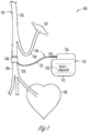
FIG. 1 is an illustration of an embodiment of a vagus nerve stimulation (VNS) system and portions of an environment in which the VNS system is used. -
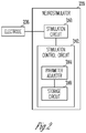
FIG. 2 is a block diagram illustrating an embodiment of an electrode and a neurostimulator of the VNS system. -
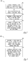
FIG. 3 is a flow chart illustrating an embodiment of a method of spatially selective VNS. -
FIG. 4 is a flow chart illustrating another embodiment of a method of spatially selective VNS. -
FIG. 5 is an illustration of a system for testing the method ofFIG. 4 . -
FIGS. 6A and 6B are illustrations of results of testing the method ofFIG. 4 . -
FIG. 7 is a flow chart illustrating an embodiment of another method of spatially selective VNS. - In the following detailed description, reference is made to the accompanying drawings which form a part hereof, and in which is shown by way of illustration specific embodiments in which the invention may be practiced. The following detailed description provides examples, and the scope of the present invention is defined by the appended claims and their legal equivalents.
- It should be noted that references to "an", "one", or "various" embodiments in this disclosure are not necessarily to the same embodiment, and such references contemplate more than one embodiment.
- This document discusses a method and system for stimulating the vagus nerve to modulate one or more target functions while minimizing stimulation-evoked side effects. Vagus nerve stimulation (VNS) has been used for the treatment of neurological disorders including depression and epilepsy. VNS is also investigated for treatment of various disorders such as Alzheimer's disease, anxiety, heart failure, and obesity.
- The vagus nerve originates in the medulla and targets multiple organs in a person's body through a complex functional innervation pattern. There are both efferent and afferent nerve fibers within the vagus nerve trunk that convey neural activities to and from visceral organs such as the esophagus, gastrointestinal tract, kidney and pancreas (abdominal branch of vagus), thoracic organs such as the heart and lungs (thoracic branch of vagus), and voluntary muscles of the neck and multiple segments of the upper airway (recurrent laryngeal nerve, RLN). Such complexity has been significantly limiting the effectiveness of VNS and the overall patient population that may benefit from this therapy.
- The difficulty in therapeutic application of VNS is further complicated by the total number of fibers within the vagus nerve trunk and the distribution of nerve fibers having different diameter. In an adult dog, which has been used as an animal model for the human vagus nerve, the cervical vagus nerve trunk contains approximately 20,000 myelinated neurons and an even greater number of unmyelinated neurons. Both the human and canine vagus nerves also share a common classification scheme defined by the diameter of nerve fibers. This is based on the classical designation of A (myelinated), B (myelinated parasympathetic) and C (unmyelinated) type fibers, as summarized in Table 1.
Table 1. Summary of Vagus Nerve Fiber Type Properties. A-Fibers B-Fibers C-Fibers Diameter (µm) 5-20 1-3 0.2-2 Myelinated Yes Yes No Conduction Velocity (m/s) 30-120 3-20 0.3-2 Per-Unit Latencies (ms/cm) 0.08-0.3 0.5-3.3 5-33.3 - Currently, a typical site of electrode implantation for VNS therapy is at the cervical spinal level between the thyroid cartilage and the sternum of the patient. At this location, the vagus nerve contains a wide array of nerve fibers, as summarized in Table 1. As a result, stimulation parameters used for VNS therapy are largely determined by titrating the various temporal properties of the electrical pulses (e.g., amplitude, frequency, duty cycle). Various studies applying VNS to animal models and human patients led to the establishment of recommended clinical parameters for antiepileptic and other applications of VNS. However, stimulation-evoked side effects, such as voice hoarseness, coughing, and pain, remain a problem in applying VNS therapy. These unwanted effects of VNS result from (1) the reversed recruitment order of myelinated nerve fibers during electrical stimulation (i.e., lower activation threshold for larger diameter fibers) and (2) the vast majority of larger diameter fibers within the vagus nerve innervate the voice box and upper airway via the RLN. Delivering electrical stimulation to the vagus nerve through bipolar helical nerve cuff electrode, for example, is known to result in non-selective activation of all nerve fibers within the nerve trunk, and hence little control over unintended generation of side-effects including unintended laryngeal activities.
- The present method and system provide for spatially selective activation of vagus nerve branches to maximize overall therapeutic efficacy of VNS. In this document, "spatially selective activation of vagus nerve branches" refers to activation of one or more selected (or specified) vagus nerve branches by delivering electrical stimulation to a space, such as a particular segment or branch of the vagus nerve, identified to allow for activation of the one or more selected vagus nerve branches without causing an unwanted side effect such as activated of a non-selected vagus nerve branch. By targeting on selected branches or fascicles of the vagus nerve using electrode placement and/or selection, the electrical stimulation is delivered to activate one or more target nerve pathways while minimizing activation of one or more non-target nerve pathways associated with stimulation-evoked side effects. In one embodiment, VNS is delivered to a thoracic vagus nerve (tVN) in a location separate from the RLN to allow placement of an electrode on the tVN but isolated from the RLN, such that the delivery of the electrical stimulation through this electrode results in desirable modulation of cardiovascular functions without evoking unwanted laryngeal activities. Surgical separation of a portion of the tVN from the RLN may be required to create adequate space for such electrode placement. In another embodiment, the topographical organization of the nerve fascicles of the cervical vagus nerve trunk allows target selection using a single multi-contact nerve electrode. The contacts in the nerve electrode are selected for delivering VNS to result in the desirable modulation of cardiovascular functions without evoking the unwanted side effects caused by activation of one or more non-targeted fibers of the vagus nerve. While efferent laryngeal muscle contraction is discussed as a specific example of the unwanted side effects to be avoided using the present method and system, the present subject matter applies to control of unwanted side effects by spatially selective activation of vagus nerve branches. Another example of such unwanted side effects to be avoided using the present method and system includes airway reflexes evoked by (1) direct activation of afferent RLN fibers and/or (2) indirect activation of afferent RLN activity generated by efferent laryngeal muscle contractions.
-
FIG. 1 is an illustration of an embodiment of aVNS system 100 and portions of an environment in whichsystem 100 is used.FIG. 1 shows a portion of avagus nerve 101 having segments or branches including a cervicalvagus nerve trunk 102, atVN 104, and anRLN 106. In the illustrated embodiment, the physical separation betweentVN 104 andRLN 106 after they diverge from cervicalvagus nerve trunk 102 allows placement of astimulation electrode 136 ontVN 104.Electrode 136 allows for delivery of VNS totVN 104, which innervates thoracic organs, including aheart 105, and abdominal organs through further branches of the vagus nerve, without activating the RLN, which innervates laryngeal muscles (represented inFIG. 1 by a laryngeal muscle 107). The physical separation betweentVN 104 andRLN 106 may be created or partially created by surgery to allow for proper placement ofelectrode 136 without affecting neural conduction within these nerve branches. In one embodiment,tVN 104 andRLN 106 are longitudinally separated by dissecting the portion of the vagus nerve trunk including these two branches to the location where fibers oftVN 104 andRLN 106 diverge, at approximately the level of the subclavian artery. In one embodiment,electrode 136 is placed ontVN 104 within about one centimeter from the location wheretVN 104 andRLN 106 diverge. - While the
application involving tVN 104 andRLN 106 as illustrated inFIG. 1 is discussed as a specific example in this document, the present method may apply to other branches of the vagus nerve or other nerves being targets of neurostimulation. In various embodiments, a portion of a nerve trunk such as a vagus nerve trunk including a first branch and a second branch is dissected to separate the first and second branches. The first branch controls one or more physiological functions of a patient. The second branch controls one or more other physiological functions of the patient. The first branch includes the stimulation site to which the electrical stimulation is delivered. The second branch is a non-target branch that is not intended to be activated by the electrical stimulation pulses. The one or more target branches, which include but are not limited to the first branch, are intended to be activated by the electrical stimulation. The stimulation electrode is placed on the first branch to allow for delivery of electrical stimulation to activate one or more target branches of the nerve trunk (including the first branch) without activating the second branch. - In the illustrated embodiment,
system 100 includes an implantablemedical device 110 electrically coupled toelectrode 136 through animplantable lead 130. Implantablemedical device 110 includes aneurostimulator 120 encapsulated by animplantable housing 112, and aheader 114 attached toimplantable housing 112 and providing for connection to lead 130.Neurostimulator 120 is discussed below with reference toFIG. 2 . In one embodiment, implantablemedical device 110 is a neurostimulator. In other embodiments, in addition toneurostimulator 120, implantablemedical device 110 includes one or more of a cardiac pacemaker, a cardioverter/defibrillator, a drug delivery device, a biologic therapy device, and any other monitoring or therapeutic devices. In the illustrated embodiment, lead 130 includes aproximal end 132, adistal end 133, and anelongate body 131 coupled betweenproximal end 132 anddistal end 133.Proximal end 132 is configured to be connected to implantablemedical device 110.Distal end 133 includes, or is otherwise coupled to,electrode 136.Electrode 136 is a bipolar nerve cuff electrode. In another embodiment,electrode 136 is a monopolar nerve cuff electrode, and another electrode such as a portion ofimplantable housing 112 is used. In various embodiments,electrode 136 includes any form of electrode that allows for activation oftVN 104 by electrical stimulation delivered fromneurostimulator 120. - While
FIG. 1 illustrates the embodiment in which the placement ofelectrode 136 ontVN 104 allows for VNS to modulate cardiovascular functions without evoking unwanted laryngeal activities, the present subject matter generally includes selective activation of vagus nerve branches by selecting the sites to which the electrical stimulation pulses are delivered through multiple electrodes or a multi-contact electrode. For example, a multi-contact electrode may be placed in cervicalvagus nerve trunk 102, cranial to the location wheretVN 104 andRLN 106 diverge. Stimulation is delivered through various combination of contacts of the multi-contact electrode to select one or more contacts allowing for the VNS to substantially activatetVN 104 without substantially activatingRLN 106. -
FIG. 2 is a block diagram illustrating an embodiment of anelectrode 236 and aneurostimulator 220.Electrode 236 represents an embodiment ofelectrode 136.Neurostimulator 220 represents an embodiment ofneurostimulator 120. -
Neurostimulator 220 includes astimulation circuit 240 and astimulation control circuit 242.Stimulation circuit 240 produces electrical stimulation pulses and delivers the electrical stimulation pulses toelectrode 236.Stimulation control circuit 242 controls the delivery of the electrical stimulation pulses using a plurality of stimulation parameters and includes aparameter adjuster 244 and astorage circuit 246.Parameter adjuster 244 allows for adjustment of one or more stimulation parameters of the plurality of stimulation parameters such that the intensity of the electrical stimulation pulses is provided for substantially activating one or more target branches of a nerve such as the vagus nerve without substantially activating one or more non-target branches of the nerve. In one embodiment, the plurality of stimulation parameters includes pulse amplitude, pulse width, pulse frequency, duty cycle, cycle unit, and stimulation duration. The pulse amplitude is the amplitude of each electrical stimulation pulse specified as voltage (e.g., for constant-voltage pulse) or current (e.g., for constant-current pulse). The pulse width is the duration of each electrical stimulation pulse. The pulse frequency is the frequency at which the electrical stimulation pulses are delivered and may also be specified as an inter-pulse interval being the time interval between successive pulses. The duty cycle is the ratio of a stimulation interval to the cycle unit. The electrical stimulation pulses are delivered during only the stimulation interval. The stimulation duration is the duration of a delivery of neurostimulation therapy. The cycle unit and the stimulation durations may be specified by time or number of pulses, and the duty cycles may be specified by time or number of pulses in each cycle unit. For example, "pulses delivered at a pulse frequency of 20 Hz at a duty cycle of 10% and a unit cycle of 1 second" is equivalent to "pulses delivered at a pulse frequency of 20 Hz at a duty cycle of 2 pulses per unit cycle of 20 pulses". -
Storage circuit 246 stores values for the plurality of stimulation parameters. In one embodiment,storage circuit 246 stores values of the one or more stimulation parameters selected to substantially activate the one or more target branches of the nerve without substantially activating the one or more non-target branches of the nerve. In one embodiment, a value of the pulse amplitude is selected to substantially activate the one or more target branches of the nerve without substantially activating the one or more non-target branches of the nerve, and stored instorage circuit 246. - In various embodiments, the circuit of
neurostimulator 220, including its various elements discussed in this document, is implemented using a combination of hardware and software. In various embodiments,stimulation control circuit 242 may be implemented using an application-specific circuit constructed to perform one or more particular functions or a general-purpose circuit programmed to perform such function(s). Such a general-purpose circuit includes, but is not limited to, a microprocessor or a portion thereof, a microcontroller or portions thereof, and a programmable logic circuit or a portion thereof. -
FIG. 3 is a flow chart illustrating an embodiment of amethod 300 of spatially selective VNS. In one embodiment,method 300 is performed usingsystem 100 including its embodiments discussed in this document. - At 310, if necessary for electrode placement, a portion of the vagus nerve including a first branch and a second branch is longitudinally dissected and separated, without damaging the normal neural conduction in these branches. At 320, an electrode, such as a nerve cuff electrode, is placed on or adjacent to the first branch.
- At 330, electrical stimulation pulses are delivered to the first branch through the electrode placed on the first branch. At 340, the delivery of the electrical stimulation pulses is controlled to substantially activate one or more target branches of the vagus nerve, including the first branch, without substantially activating the second branch. This includes adjusting one or more stimulation parameters controlling the intensity of the electrical stimulation pulses. In one embodiment, the one or more stimulation parameters are determined by monitoring neural signals and/or myoelectric signals indicative of the activation of the one or more target branches and the second branch. Surgical separation at 310 is not necessary if the electrode can be placed on or adjacent to the first branch to allow substantial activation of the one or more target branches of the vagus nerve, including the first branch, without substantially activating the second branch. In this document, substantially activating a nerve means causing a detectable stimulation-evoked neural response. Such stimulation-evoked neural response may be detected, for example, by sensing neural traffic in the nerve and/or sensing a signal indicative of a physiological function modulated by the neural traffic.
-
FIG. 4 is a flow chart illustrating an embodiment of amethod 400 of spatially selective VNS.Method 400 includes an embodiment ofmethod 300 with the first branch of the vagusnerve being tVN 104 and the second branch of the vagusnerve being RLN 106. In one embodiment,method 400 is performed usingsystem 100 including its embodiments discussed in this document. - At 410, electrical stimulation pulses are delivered to
tVN 104, which has been longitudinally separated fromRLN 106. At 420, the intensity of the electrical stimulation pulses is controlled for substantially activating one or more target branches of the vagus nerve without causing contraction of a laryngeal muscle that is innervated byRLN 106. - In one embodiment, this intensity is determined by sensing signals representative and/or indicative of the neural responses to the delivery of the stimulation pulses. For example, a stimulation-evoked electroneurographic (ENG) signal representative of a response of the cervical vagus nerve trunk to the electrical stimulation pulses is sensed, and a stimulation-evoked electromyographic (EMG) indicative of the response of the RLN to the electrical stimulation pulses is sensed. The one or more target branches of the vagus nerve are considered to be substantially activated when the amplitude of the ENG signal exceeds a specified ENG threshold. The contraction of a laryngeal muscle is not considered to be occurring, or the RLN is not considered to be activated, when the amplitude of the EMG signal does not exceed a specified EMG threshold. In one embodiment, the intensity of the electrical stimulation pulses is determined by adjusting the pulse amplitude and/or the pulse width and observing the effect of the adjustment on the amplitude of the ENG signal and the amplitude of the EMG signal.
-
FIG. 5 is an illustration of asystem 500 fortesting method 400. Thevagus nerve 101 is dissected distally to approximately the level of the subclavian artery where multiple branches of the vagus nerve trunk can be separated and identified.RLN 106 and the remaining part of the vagus nerve (tVN 104) are isolated and instrumented with individual nerve cuff electrodes 538 (on or adjacent to RLN 106) and 536 (on or adjacent to tVN 104). A tripolarnerve cuff electrode 566 is implanted on cervicalvagus nerve trunk 102 to record antidromic ENG activity, and anelectrode 556 including a pair of insulated stainless steel wires was inserted into laryngeal muscle 107 (e.g., the posterior cricoarytenoid muscle) to measure laryngeal EMG. - A
first neurostimulator 520A is electrically connected to electrode 536 to deliver electrical stimulation pulses totVN 104. Asecond neurostimulator 520B is electrically connected to electrode 538 to deliver electrical stimulation pulses toRLN 106. An example for each offirst neurostimulator 520A andsecond neurostimulator 520B is neurostimulator 220 as discussed above. For the purpose of the test,first neurostimulator 520A andsecond neurostimulator 520B may include one device being used asfirst neurostimulator 520A andsecond neurostimulator 520B at different times, or two devices that can be used concurrently or at different times.First neurostimulator 520A andsecond neurostimulator 520B may each be an implantable device or an external device that is electrically coupled to the corresponding electrode via an implantable or percutaneous lead. Aneural sensing circuit 560 is electrically coupled toelectrode 566 and senses a stimulation-evoked ENG signal representative of a response of cervicalvagus nerve trunk 102 to the electrical stimulation pulses delivered totVN 104 and the electrical stimulation pulses delivered toRLN 106. AnENG parameter producer 562 produces an amplitude of the ENG signal indicative of the response of cervicalvagus nerve trunk 102 using the sensed ENG signal. Amyoelectric sensing circuit 550 is electrically coupled toelectrode 556 and senses a stimulation-evoked EMG signal indicative of the response to the electrical stimulation pulses delivered totVN 104 and the electrical stimulation pulses delivered toRLN 106. AnEMG parameter producer 552 produces an amplitude of the EMG signal indicative of the response of the laryngeal muscle using the sensed EMG signal. -
FIGS. 6A and 6B are illustrations of results oftesting method 400. The feasibility of selectively activating individual branches of the vagus nerve was investigated using a canine model andsystem 500.FIGS. 6A and 6B show recruitment curves obtained by recording the stimulation-evoked ENG and EMG activities, which demonstrates a clear separation of nerves innervating the larynx from those of the vagus nerve that continued distally into the thorax.FIG. 6A shows that during selective RLN stimulation (through electrode 538), the concomitant activation of low-threshold A-fibers (current = 0.5 mA) and laryngeal EMG activity indicates a strong correlation between these large diameter fibers and muscles of the larynx. In contrast,FIG. 6B shows that selective stimulation of the tVN (throughelectrode 536, for which a monopolar nerve cuff electrode was used) has a significantly higher threshold for activating ENG activity (current = 2 mA), which reaches a plateau at approximately 4 mA. The activation of laryngeal EMG activity above 4 mA indicates that the threshold at which the tVN stimulation current spills over into the adjacent RLN branch, thus indicating a need to adjust stimulation intensity. - These results show that the anatomical divergence of multiple branches of the vagus nerve allows for selectively stimulating specific subsets of nerves within the vagus nerve to achieve desirable therapeutic effects while minimizing side-effects. The topographical organization of the nerve fascicles also allows for use of a single multi-contact nerve electrode as the neural interface for an implanted device.
- In various embodiments, spatially selective VNS is applied by selecting a stimulation site on a specific nerve branch and a stimulation intensity to substantially activate the one or more target branches of the vagus nerve without substantially activating one or more non-target branches of the vagus nerve. A nerve is substantially activated when the stimulation-evoked neural response is detectable (such as when the amplitude of an ENG signal is at or above a specified ENG threshold) or when a stimulation-evoked response being a physiological function controlled by the nerve is detectable (such as when the amplitude of the EMG signal is at or above a specified EMG threshold). Likewise, a nerve is not substantially activated when the stimulation-evoked neural response is not detectable (such as when the amplitude of an ENG signal is below a specified ENG threshold) or when a stimulation-evoked response being a physiological function controlled by the nerve is detectable (such as when the amplitude of the EMG signal is below a specified EMG threshold).
-
FIG. 7 is a flow chart illustrating an embodiment of amethod 700 of spatially selective VNS. In one embodiment,method 700 is performed usingsystem 100 including its embodiments discussed in this document, withelectrode 136 being a multi-contact electrode. - At 710, a multi-contact electrode is placed on cervical
vagus nerve trunk 102 cranial to the location wheretVN 104 andRLN 106 diverge. The contacts of the multi-contact electrode are distributed to allow selective stimulation of the fascicles of cervicalvagus nerve trunk 102. At 720, one or more contacts of the multi-contact electrode are selected for substantially activating one or more target branches of the vagus nerve without causing contraction of a laryngeal muscle that is innervated byRLN 106. Electrical stimulation pulses are delivered through various contacts or combination of contacts to identify the one or more contacts to be selected.Stimulation control circuit 242 controls the delivery of the electrical stimulation pulses using the plurality of stimulation parameters including one or more stimulation parameters specifying the selection of the one or more contacts of the multi-contact electrode.Parameter adjuster 244 adjusts the one or more stimulation parameters during the process of selecting the one or more contacts. The one or more stimulation parameters specifying the one or more contact selected at completion of this process are stored instorage circuit 246 for the subsequent VNS therapy. - In one embodiment, the electrical stimulation pulses are delivered using at least two contacts of the multi-contact electrode used as a bipolar electrode. In another embodiment, the electrical stimulation pulses are delivered using at least one contact of the multi-contact electrode used as a monopolar electrode and a separate electrode.
- In one embodiment, this process of selecting the one or more contacts includes sensing signals representative and/or indicative of the neural responses to the delivery of the stimulation pulses. For example, a stimulation-evoked electroneurographic (ENG) signal representative of a response of the cervical vagus nerve trunk to the electrical stimulation pulses is sensed, and a stimulation-evoked electromyographic (EMG) indicative of the response of the RLN to the electrical stimulation pulses is sensed. The one or more target branches of the vagus nerve are considered to be substantially activated when the amplitude of the ENG signal exceeds a specified ENG threshold. The contraction of a laryngeal muscle is not considered to be occurring, or the RLN is not considered to be activated, when the amplitude of the EMG signal does not exceed a specified EMG threshold. In one embodiment, the process of selecting the one or more contacts includes sweeping through various contacts and/or combination of contacts of the multi-contact electrode and observing the effect of the adjustment on the amplitude of the ENG signal and the amplitude of the EMG signal.
- It is to be understood that the above detailed description is intended to be illustrative, and not restrictive. Other embodiments will be apparent to those of skill in the art upon reading and understanding the above description. The scope of the invention should, therefore, be determined with reference to the appended claims.
Claims (8)
- A system (500) for stimulating a vagus nerve having multiple branches, the system comprising:a first electrode (536) configured to be placed on a first branch of the vagus nerve to allow for delivery of electrical stimulation pulses to the first branch;a second electrode (538) configured to be placed on a second branch of the vagus nerve to allow for delivery of electrical stimulation pulses to the second branch;a neural sensing circuit (560) configured to sense a stimulation-evoked electroneurographic (ENG) signal representative of a response of the vagus nerve to the electrical stimulation pulses;an ENG-sensing electrode (566) being a tripolar nerve cuff electrode coupled to the neural sensing circuit for sensing the stimulation-evoked ENG signal;an ENG parameter producer (562) configured to produce an amplitude of the ENG signal;a myoelectric sensing circuit (550) configured to sense a stimulation-evoked electromyographic (EMG) signal representative of a response of a muscle to the electrical stimulation pulses, the muscle innervated by a second branch of the vagus nerve;an EMG-sensing electrode (556) including a pair of wires coupled to the myoelectric sensing circuit for sensing the stimulation-evoked EMG signal;an EMG parameter producer (552) configured to produce an amplitude of the EMG signal; anda first neurostimulator (220, 520A) and a second neurostimulator (220, 520B), each including:a stimulation circuit (240) configured to deliver the electrical stimulation pulses to the branch of the vagus nerve through the electrode; anda stimulation control circuit (242) configured to control the delivery of the electrical stimulation pulses using a plurality of stimulation parameters, the stimulation control circuit including a parameter adjuster (244) configured to allow for adjustment of one or more stimulation parameters of the plurality of stimulation parameters using the ENG signal and the EMG signal,wherein the stimulation circuit (240) of the first neurostimulator (220, 520A) is configured to deliver the electrical stimulation pulses to the first branch of the vagus nerve and the stimulation circuit (240) of the second neurostimulator (220, 520B) is configured to deliver the electrical stimulation pulses to the second branch of the vagus nerve.
- The system according to claim 1, wherein the first electrode (536) comprises a cuff electrode.
- The system according to any of claims 1 and 2, wherein the stimulation control circuit comprises a storage circuit (246) configured to store the one or more stimulation parameters adjusted for an amplitude of the ENG signal exceeding a specified ENG threshold and an amplitude of the EMG signal below a specified EMG threshold.
- The system of claim 1, wherein the parameter adjuster (244) is configured to adjust a pulse amplitude being an amplitude of each pulse of the electrical stimulation pulses.
- The system of claim 1, wherein the parameter adjuster (244) is configured to adjust a pulse width being a duration of each pulse of the electrical stimulation pulses.
- The system of claim 1, wherein the parameter adjuster (244) is configured to adjust a pulse frequency being a frequency at which the electrical stimulation pulses are delivered.
- The system of claim 1, wherein the parameter adjuster (244) is configured to adjust a duty cycle at which the electrical stimulation pulses are delivered.
- The system of claim1, wherein the first neurostimulator (520A) and the second neurostimulator (520B) include one device configured to be used as first neurostimulator (520A) and second neurostimulator (520B) at different times, or two devices that are configured to be used concurrently or at different times.
Applications Claiming Priority (2)
| Application Number | Priority Date | Filing Date | Title |
|---|---|---|---|
| US35118110P | 2010-06-03 | 2010-06-03 | |
| PCT/US2011/037726 WO2011153024A1 (en) | 2010-06-03 | 2011-05-24 | System for spatially selective vagus nerve stimulation |
Publications (2)
| Publication Number | Publication Date |
|---|---|
| EP2575961A1 EP2575961A1 (en) | 2013-04-10 |
| EP2575961B1 true EP2575961B1 (en) | 2018-08-29 |
Family
ID=44627009
Family Applications (1)
| Application Number | Title | Priority Date | Filing Date |
|---|---|---|---|
| EP11725562.0A Not-in-force EP2575961B1 (en) | 2010-06-03 | 2011-05-24 | System for spatially selective vagus nerve stimulation |
Country Status (4)
| Country | Link |
|---|---|
| US (2) | US8509919B2 (en) |
| EP (1) | EP2575961B1 (en) |
| JP (1) | JP5769036B2 (en) |
| WO (1) | WO2011153024A1 (en) |
Families Citing this family (41)
| Publication number | Priority date | Publication date | Assignee | Title |
|---|---|---|---|---|
| EP1909694B1 (en) | 2005-07-25 | 2014-06-11 | Rainbow Medical Ltd. | Electrical stimulation of blood vessels |
| CA2676119C (en) | 2007-01-29 | 2021-01-19 | Simon Fraser University | Transvascular nerve stimulation apparatus and methods |
| AU2008297476B2 (en) | 2007-09-13 | 2011-09-15 | Cardiac Pacemakers, Inc. | Systems for avoiding neural stimulation habituation |
| US8538535B2 (en) | 2010-08-05 | 2013-09-17 | Rainbow Medical Ltd. | Enhancing perfusion by contraction |
| US9005106B2 (en) | 2008-01-31 | 2015-04-14 | Enopace Biomedical Ltd | Intra-aortic electrical counterpulsation |
| JP5769036B2 (en) | 2010-06-03 | 2015-08-26 | カーディアック ペースメイカーズ, インコーポレイテッド | System for spatially selective vagus nerve stimulation |
| US9980645B1 (en) * | 2011-06-21 | 2018-05-29 | Case Western Reserve University | High-contact density electrode and fabrication technique for an implantable cuff design |
| US9526637B2 (en) | 2011-09-09 | 2016-12-27 | Enopace Biomedical Ltd. | Wireless endovascular stent-based electrodes |
| CN107126622A (en) | 2012-03-05 | 2017-09-05 | 西蒙·弗雷瑟大学 | neural stimulation system |
| US9855431B2 (en) | 2012-03-19 | 2018-01-02 | Cardiac Pacemakers, Inc. | Systems and methods for monitoring for nerve damage |
| EP2863987B1 (en) | 2012-06-21 | 2023-08-02 | Lungpacer Medical Inc. | Transvascular diaphragm pacing systems |
| CN105899166B (en) | 2013-11-06 | 2018-07-06 | 伊诺佩斯生医有限公司 | The intravascular electrode based on stent of radio-type |
| US9242088B2 (en) | 2013-11-22 | 2016-01-26 | Simon Fraser University | Apparatus and methods for assisted breathing by transvascular nerve stimulation |
| EP3096835B1 (en) | 2014-01-21 | 2019-08-07 | Lungpacer Medical Inc. | Systems for optimization of multi-electrode nerve pacing |
| US9974597B2 (en) * | 2014-03-19 | 2018-05-22 | Boston Scientific Scimed, Inc. | Systems and methods for assessing and treating tissue |
| EP2946806B1 (en) | 2014-05-19 | 2016-07-27 | Sorin CRM SAS | Active implantable medical device with automatic optimisation of the configuration of a multi-electrode stimulation probe, in particular a probe for selective stimulation of the vagus nerve |
| US9782584B2 (en) | 2014-06-13 | 2017-10-10 | Nervana, LLC | Transcutaneous electrostimulator and methods for electric stimulation |
| US10130809B2 (en) | 2014-06-13 | 2018-11-20 | Nervana, LLC | Transcutaneous electrostimulator and methods for electric stimulation |
| US10646715B2 (en) | 2014-07-23 | 2020-05-12 | United States Government As Represented By The Department Of Veterans Affairs | Parasympathetic activation by vagus nerve stimulation |
| AU2015301401B2 (en) | 2014-08-15 | 2020-01-16 | Axonics Modulation Technologies, Inc. | Electromyographic lead positioning and stimulation titration in a nerve stimulation system for treatment of overactive bladder |
| US9855423B2 (en) | 2014-08-15 | 2018-01-02 | Axonics Modulation Technologies, Inc. | Systems and methods for neurostimulation electrode configurations based on neural localization |
| US10092762B2 (en) | 2014-08-15 | 2018-10-09 | Axonics Modulation Technologies, Inc. | Integrated electromyographic clinician programmer for use with an implantable neurostimulator |
| WO2016182894A1 (en) * | 2015-05-08 | 2016-11-17 | Duke University | Systems and methods for spinal cord stimulation |
| CN108882885A (en) | 2016-01-20 | 2018-11-23 | 赛博恩特医疗器械公司 | The control of vagal stimulation |
| US11471681B2 (en) | 2016-01-20 | 2022-10-18 | Setpoint Medical Corporation | Batteryless implantable microstimulators |
| US10293164B2 (en) | 2017-05-26 | 2019-05-21 | Lungpacer Medical Inc. | Apparatus and methods for assisted breathing by transvascular nerve stimulation |
| US20190001126A1 (en) | 2017-06-30 | 2019-01-03 | Lungpacer Medical Inc. | Devices and methods for prevention, moderation, and/or treatment of cognitive injury |
| US10195429B1 (en) | 2017-08-02 | 2019-02-05 | Lungpacer Medical Inc. | Systems and methods for intravascular catheter positioning and/or nerve stimulation |
| US10940308B2 (en) | 2017-08-04 | 2021-03-09 | Lungpacer Medical Inc. | Systems and methods for trans-esophageal sympathetic ganglion recruitment |
| US11173307B2 (en) | 2017-08-14 | 2021-11-16 | Setpoint Medical Corporation | Vagus nerve stimulation pre-screening test |
| US11260229B2 (en) | 2018-09-25 | 2022-03-01 | The Feinstein Institutes For Medical Research | Methods and apparatuses for reducing bleeding via coordinated trigeminal and vagal nerve stimulation |
| EP3877043A4 (en) | 2018-11-08 | 2022-08-24 | Lungpacer Medical Inc. | Stimulation systems and related user interfaces |
| AU2020272128A1 (en) * | 2019-04-12 | 2021-12-09 | Setpoint Medical Corporation | Vagus nerve stimulation to treat neurodegenerative disorders |
| WO2020232333A1 (en) | 2019-05-16 | 2020-11-19 | Lungpacer Medical Inc. | Systems and methods for sensing and stimulation |
| US11439829B2 (en) | 2019-05-24 | 2022-09-13 | Axonics, Inc. | Clinician programmer methods and systems for maintaining target operating temperatures |
| US11848090B2 (en) | 2019-05-24 | 2023-12-19 | Axonics, Inc. | Trainer for a neurostimulator programmer and associated methods of use with a neurostimulation system |
| US11771900B2 (en) | 2019-06-12 | 2023-10-03 | Lungpacer Medical Inc. | Circuitry for medical stimulation systems |
| US11938324B2 (en) | 2020-05-21 | 2024-03-26 | The Feinstein Institutes For Medical Research | Systems and methods for vagus nerve stimulation |
| WO2022077439A1 (en) * | 2020-10-16 | 2022-04-21 | 深圳先进技术研究院 | Wearable infrared navigation ultrasonic stimulation system |
| EP4333972A1 (en) * | 2021-05-07 | 2024-03-13 | Battelle Memorial Institute | Distributed device control and wearable system for vagus nerve stimulation |
| US11400299B1 (en) | 2021-09-14 | 2022-08-02 | Rainbow Medical Ltd. | Flexible antenna for stimulator |
Family Cites Families (23)
| Publication number | Priority date | Publication date | Assignee | Title |
|---|---|---|---|---|
| US5700282A (en) * | 1995-10-13 | 1997-12-23 | Zabara; Jacob | Heart rhythm stabilization using a neurocybernetic prosthesis |
| WO1997045160A1 (en) | 1996-05-31 | 1997-12-04 | Southern Illinois University | Methods of modulating aspects of brain neural plasticity by vagus nerve stimulation |
| US6341236B1 (en) | 1999-04-30 | 2002-01-22 | Ivan Osorio | Vagal nerve stimulation techniques for treatment of epileptic seizures |
| US6466822B1 (en) | 2000-04-05 | 2002-10-15 | Neuropace, Inc. | Multimodal neurostimulator and process of using it |
| US6892098B2 (en) * | 2001-04-26 | 2005-05-10 | Biocontrol Medical Ltd. | Nerve stimulation for treating spasticity, tremor, muscle weakness, and other motor disorders |
| GB2388966A (en) | 2002-05-24 | 2003-11-26 | Cbs Products Ltd | Cable blowing machine |
| US7203548B2 (en) * | 2002-06-20 | 2007-04-10 | Advanced Bionics Corporation | Cavernous nerve stimulation via unidirectional propagation of action potentials |
| US7174218B1 (en) * | 2003-08-12 | 2007-02-06 | Advanced Bionics Corporation | Lead extension system for use with a microstimulator |
| US20050137645A1 (en) | 2003-12-05 | 2005-06-23 | Juha Voipio | Novel method for the adjustment of human and animal vagus nerve stimulation |
| WO2006102591A2 (en) * | 2005-03-24 | 2006-09-28 | Vanderbilt University | Respiratory triggered, bilateral laryngeal stimulator to restore normal ventilation in vocal fold paralysis |
| US8036750B2 (en) * | 2005-06-13 | 2011-10-11 | Cardiac Pacemakers, Inc. | System for neural control of respiration |
| US7672728B2 (en) * | 2005-12-28 | 2010-03-02 | Cardiac Pacemakers, Inc. | Neural stimulator to treat sleep disordered breathing |
| US8103341B2 (en) * | 2006-08-25 | 2012-01-24 | Cardiac Pacemakers, Inc. | System for abating neural stimulation side effects |
| US8050765B2 (en) | 2006-08-30 | 2011-11-01 | Cardiac Pacemakers, Inc. | Method and apparatus for controlling neural stimulation during disordered breathing |
| US8121692B2 (en) | 2006-08-30 | 2012-02-21 | Cardiac Pacemakers, Inc. | Method and apparatus for neural stimulation with respiratory feedback |
| US7801603B2 (en) * | 2006-09-01 | 2010-09-21 | Cardiac Pacemakers, Inc. | Method and apparatus for optimizing vagal nerve stimulation using laryngeal activity |
| US8233982B2 (en) * | 2007-02-21 | 2012-07-31 | Cardiac Pacemakers, Inc. | Systems and methods for treating supraventricular arrhythmias |
| JP5189654B2 (en) * | 2007-12-12 | 2013-04-24 | カーディアック ペースメイカーズ, インコーポレイテッド | A stimulation system that transmits neural stimulation from the pulmonary artery |
| JP5276119B2 (en) * | 2008-02-14 | 2013-08-28 | カーディアック ペースメイカーズ, インコーポレイテッド | Method and apparatus for detection of phrenic stimulation |
| WO2010005482A1 (en) | 2008-07-08 | 2010-01-14 | Cardiac Pacemakers, Inc. | Systems for delivering vagal nerve stimulation |
| WO2010031406A1 (en) * | 2008-09-19 | 2010-03-25 | Aalborg Universitet | Cardiac related neural activity |
| WO2010051499A1 (en) * | 2008-10-31 | 2010-05-06 | Medtronic, Inc. | Therapy system including cardiac rhythm therapy and neurostimulation capabilities |
| JP5769036B2 (en) | 2010-06-03 | 2015-08-26 | カーディアック ペースメイカーズ, インコーポレイテッド | System for spatially selective vagus nerve stimulation |
-
2011
- 2011-05-24 JP JP2013513215A patent/JP5769036B2/en not_active Expired - Fee Related
- 2011-05-24 EP EP11725562.0A patent/EP2575961B1/en not_active Not-in-force
- 2011-05-24 US US13/114,626 patent/US8509919B2/en active Active
- 2011-05-24 WO PCT/US2011/037726 patent/WO2011153024A1/en active Application Filing
-
2013
- 2013-07-30 US US13/954,959 patent/US8942824B2/en not_active Expired - Fee Related
Also Published As
| Publication number | Publication date |
|---|---|
| US20110301658A1 (en) | 2011-12-08 |
| EP2575961A1 (en) | 2013-04-10 |
| US20130310893A1 (en) | 2013-11-21 |
| JP5769036B2 (en) | 2015-08-26 |
| US8509919B2 (en) | 2013-08-13 |
| JP2013530747A (en) | 2013-08-01 |
| WO2011153024A1 (en) | 2011-12-08 |
| US8942824B2 (en) | 2015-01-27 |
Similar Documents
| Publication | Publication Date | Title |
|---|---|---|
| EP2575961B1 (en) | System for spatially selective vagus nerve stimulation | |
| US9630010B2 (en) | Vagus nerve stimulation with target effects controlled by adjusting temporal parameters | |
| US10080899B2 (en) | Systems and methods for treating autonomic instability and medical conditions associated therewith | |
| US8594805B2 (en) | Systems to detect vagus capture | |
| US8874218B2 (en) | Neurostimulation with signal duration determined by a cardiac cycle | |
| CA2653110C (en) | Microburst electrical stimulation of cranial nerves for the treatment of medical conditions | |
| AU2012202408B2 (en) | Microburst electrical stimulation of cranial nerves for the treatment of medical conditions |
Legal Events
| Date | Code | Title | Description |
|---|---|---|---|
| PUAI | Public reference made under article 153(3) epc to a published international application that has entered the european phase |
Free format text: ORIGINAL CODE: 0009012 |
|
| 17P | Request for examination filed |
Effective date: 20121221 |
|
| AK | Designated contracting states |
Kind code of ref document: A1 Designated state(s): AL AT BE BG CH CY CZ DE DK EE ES FI FR GB GR HR HU IE IS IT LI LT LU LV MC MK MT NL NO PL PT RO RS SE SI SK SM TR |
|
| DAX | Request for extension of the european patent (deleted) | ||
| STAA | Information on the status of an ep patent application or granted ep patent |
Free format text: STATUS: EXAMINATION IS IN PROGRESS |
|
| 17Q | First examination report despatched |
Effective date: 20170823 |
|
| GRAP | Despatch of communication of intention to grant a patent |
Free format text: ORIGINAL CODE: EPIDOSNIGR1 |
|
| STAA | Information on the status of an ep patent application or granted ep patent |
Free format text: STATUS: GRANT OF PATENT IS INTENDED |
|
| INTG | Intention to grant announced |
Effective date: 20180418 |
|
| RIN1 | Information on inventor provided before grant (corrected) |
Inventor name: YOO, PAUL B. Inventor name: HINCAPIE ORDONEZ, JUAN GABRIEL Inventor name: GRILL, WARREN M. |
|
| GRAS | Grant fee paid |
Free format text: ORIGINAL CODE: EPIDOSNIGR3 |
|
| GRAA | (expected) grant |
Free format text: ORIGINAL CODE: 0009210 |
|
| STAA | Information on the status of an ep patent application or granted ep patent |
Free format text: STATUS: THE PATENT HAS BEEN GRANTED |
|
| AK | Designated contracting states |
Kind code of ref document: B1 Designated state(s): AL AT BE BG CH CY CZ DE DK EE ES FI FR GB GR HR HU IE IS IT LI LT LU LV MC MK MT NL NO PL PT RO RS SE SI SK SM TR |
|
| REG | Reference to a national code |
Ref country code: GB Ref legal event code: FG4D |
|
| REG | Reference to a national code |
Ref country code: CH Ref legal event code: EP |
|
| REG | Reference to a national code |
Ref country code: AT Ref legal event code: REF Ref document number: 1034422 Country of ref document: AT Kind code of ref document: T Effective date: 20180915 |
|
| REG | Reference to a national code |
Ref country code: IE Ref legal event code: FG4D |
|
| REG | Reference to a national code |
Ref country code: DE Ref legal event code: R096 Ref document number: 602011051507 Country of ref document: DE |
|
| REG | Reference to a national code |
Ref country code: NL Ref legal event code: MP Effective date: 20180829 |
|
| REG | Reference to a national code |
Ref country code: LT Ref legal event code: MG4D |
|
| PG25 | Lapsed in a contracting state [announced via postgrant information from national office to epo] |
Ref country code: LT Free format text: LAPSE BECAUSE OF FAILURE TO SUBMIT A TRANSLATION OF THE DESCRIPTION OR TO PAY THE FEE WITHIN THE PRESCRIBED TIME-LIMIT Effective date: 20180829 Ref country code: IS Free format text: LAPSE BECAUSE OF FAILURE TO SUBMIT A TRANSLATION OF THE DESCRIPTION OR TO PAY THE FEE WITHIN THE PRESCRIBED TIME-LIMIT Effective date: 20181229 Ref country code: GR Free format text: LAPSE BECAUSE OF FAILURE TO SUBMIT A TRANSLATION OF THE DESCRIPTION OR TO PAY THE FEE WITHIN THE PRESCRIBED TIME-LIMIT Effective date: 20181130 Ref country code: RS Free format text: LAPSE BECAUSE OF FAILURE TO SUBMIT A TRANSLATION OF THE DESCRIPTION OR TO PAY THE FEE WITHIN THE PRESCRIBED TIME-LIMIT Effective date: 20180829 Ref country code: NO Free format text: LAPSE BECAUSE OF FAILURE TO SUBMIT A TRANSLATION OF THE DESCRIPTION OR TO PAY THE FEE WITHIN THE PRESCRIBED TIME-LIMIT Effective date: 20181129 Ref country code: BG Free format text: LAPSE BECAUSE OF FAILURE TO SUBMIT A TRANSLATION OF THE DESCRIPTION OR TO PAY THE FEE WITHIN THE PRESCRIBED TIME-LIMIT Effective date: 20181129 Ref country code: NL Free format text: LAPSE BECAUSE OF FAILURE TO SUBMIT A TRANSLATION OF THE DESCRIPTION OR TO PAY THE FEE WITHIN THE PRESCRIBED TIME-LIMIT Effective date: 20180829 Ref country code: FI Free format text: LAPSE BECAUSE OF FAILURE TO SUBMIT A TRANSLATION OF THE DESCRIPTION OR TO PAY THE FEE WITHIN THE PRESCRIBED TIME-LIMIT Effective date: 20180829 Ref country code: SE Free format text: LAPSE BECAUSE OF FAILURE TO SUBMIT A TRANSLATION OF THE DESCRIPTION OR TO PAY THE FEE WITHIN THE PRESCRIBED TIME-LIMIT Effective date: 20180829 |
|
| REG | Reference to a national code |
Ref country code: AT Ref legal event code: MK05 Ref document number: 1034422 Country of ref document: AT Kind code of ref document: T Effective date: 20180829 |
|
| PG25 | Lapsed in a contracting state [announced via postgrant information from national office to epo] |
Ref country code: HR Free format text: LAPSE BECAUSE OF FAILURE TO SUBMIT A TRANSLATION OF THE DESCRIPTION OR TO PAY THE FEE WITHIN THE PRESCRIBED TIME-LIMIT Effective date: 20180829 Ref country code: LV Free format text: LAPSE BECAUSE OF FAILURE TO SUBMIT A TRANSLATION OF THE DESCRIPTION OR TO PAY THE FEE WITHIN THE PRESCRIBED TIME-LIMIT Effective date: 20180829 Ref country code: AL Free format text: LAPSE BECAUSE OF FAILURE TO SUBMIT A TRANSLATION OF THE DESCRIPTION OR TO PAY THE FEE WITHIN THE PRESCRIBED TIME-LIMIT Effective date: 20180829 |
|
| PG25 | Lapsed in a contracting state [announced via postgrant information from national office to epo] |
Ref country code: CZ Free format text: LAPSE BECAUSE OF FAILURE TO SUBMIT A TRANSLATION OF THE DESCRIPTION OR TO PAY THE FEE WITHIN THE PRESCRIBED TIME-LIMIT Effective date: 20180829 Ref country code: AT Free format text: LAPSE BECAUSE OF FAILURE TO SUBMIT A TRANSLATION OF THE DESCRIPTION OR TO PAY THE FEE WITHIN THE PRESCRIBED TIME-LIMIT Effective date: 20180829 Ref country code: EE Free format text: LAPSE BECAUSE OF FAILURE TO SUBMIT A TRANSLATION OF THE DESCRIPTION OR TO PAY THE FEE WITHIN THE PRESCRIBED TIME-LIMIT Effective date: 20180829 Ref country code: PL Free format text: LAPSE BECAUSE OF FAILURE TO SUBMIT A TRANSLATION OF THE DESCRIPTION OR TO PAY THE FEE WITHIN THE PRESCRIBED TIME-LIMIT Effective date: 20180829 Ref country code: ES Free format text: LAPSE BECAUSE OF FAILURE TO SUBMIT A TRANSLATION OF THE DESCRIPTION OR TO PAY THE FEE WITHIN THE PRESCRIBED TIME-LIMIT Effective date: 20180829 Ref country code: RO Free format text: LAPSE BECAUSE OF FAILURE TO SUBMIT A TRANSLATION OF THE DESCRIPTION OR TO PAY THE FEE WITHIN THE PRESCRIBED TIME-LIMIT Effective date: 20180829 |
|
| PG25 | Lapsed in a contracting state [announced via postgrant information from national office to epo] |
Ref country code: SM Free format text: LAPSE BECAUSE OF FAILURE TO SUBMIT A TRANSLATION OF THE DESCRIPTION OR TO PAY THE FEE WITHIN THE PRESCRIBED TIME-LIMIT Effective date: 20180829 Ref country code: DK Free format text: LAPSE BECAUSE OF FAILURE TO SUBMIT A TRANSLATION OF THE DESCRIPTION OR TO PAY THE FEE WITHIN THE PRESCRIBED TIME-LIMIT Effective date: 20180829 Ref country code: SK Free format text: LAPSE BECAUSE OF FAILURE TO SUBMIT A TRANSLATION OF THE DESCRIPTION OR TO PAY THE FEE WITHIN THE PRESCRIBED TIME-LIMIT Effective date: 20180829 |
|
| REG | Reference to a national code |
Ref country code: DE Ref legal event code: R097 Ref document number: 602011051507 Country of ref document: DE |
|
| PLBE | No opposition filed within time limit |
Free format text: ORIGINAL CODE: 0009261 |
|
| STAA | Information on the status of an ep patent application or granted ep patent |
Free format text: STATUS: NO OPPOSITION FILED WITHIN TIME LIMIT |
|
| PGFP | Annual fee paid to national office [announced via postgrant information from national office to epo] |
Ref country code: IT Payment date: 20190527 Year of fee payment: 9 Ref country code: DE Payment date: 20190514 Year of fee payment: 9 |
|
| 26N | No opposition filed |
Effective date: 20190531 |
|
| PG25 | Lapsed in a contracting state [announced via postgrant information from national office to epo] |
Ref country code: SI Free format text: LAPSE BECAUSE OF FAILURE TO SUBMIT A TRANSLATION OF THE DESCRIPTION OR TO PAY THE FEE WITHIN THE PRESCRIBED TIME-LIMIT Effective date: 20180829 |
|
| REG | Reference to a national code |
Ref country code: CH Ref legal event code: PL |
|
| GBPC | Gb: european patent ceased through non-payment of renewal fee |
Effective date: 20190524 |
|
| PG25 | Lapsed in a contracting state [announced via postgrant information from national office to epo] |
Ref country code: CH Free format text: LAPSE BECAUSE OF NON-PAYMENT OF DUE FEES Effective date: 20190531 Ref country code: LI Free format text: LAPSE BECAUSE OF NON-PAYMENT OF DUE FEES Effective date: 20190531 Ref country code: MC Free format text: LAPSE BECAUSE OF FAILURE TO SUBMIT A TRANSLATION OF THE DESCRIPTION OR TO PAY THE FEE WITHIN THE PRESCRIBED TIME-LIMIT Effective date: 20180829 |
|
| REG | Reference to a national code |
Ref country code: BE Ref legal event code: MM Effective date: 20190531 |
|
| PG25 | Lapsed in a contracting state [announced via postgrant information from national office to epo] |
Ref country code: LU Free format text: LAPSE BECAUSE OF NON-PAYMENT OF DUE FEES Effective date: 20190524 |
|
| PG25 | Lapsed in a contracting state [announced via postgrant information from national office to epo] |
Ref country code: TR Free format text: LAPSE BECAUSE OF FAILURE TO SUBMIT A TRANSLATION OF THE DESCRIPTION OR TO PAY THE FEE WITHIN THE PRESCRIBED TIME-LIMIT Effective date: 20180829 |
|
| PG25 | Lapsed in a contracting state [announced via postgrant information from national office to epo] |
Ref country code: IE Free format text: LAPSE BECAUSE OF NON-PAYMENT OF DUE FEES Effective date: 20190524 Ref country code: GB Free format text: LAPSE BECAUSE OF NON-PAYMENT OF DUE FEES Effective date: 20190524 |
|
| PG25 | Lapsed in a contracting state [announced via postgrant information from national office to epo] |
Ref country code: BE Free format text: LAPSE BECAUSE OF NON-PAYMENT OF DUE FEES Effective date: 20190531 |
|
| PG25 | Lapsed in a contracting state [announced via postgrant information from national office to epo] |
Ref country code: PT Free format text: LAPSE BECAUSE OF FAILURE TO SUBMIT A TRANSLATION OF THE DESCRIPTION OR TO PAY THE FEE WITHIN THE PRESCRIBED TIME-LIMIT Effective date: 20181229 Ref country code: FR Free format text: LAPSE BECAUSE OF NON-PAYMENT OF DUE FEES Effective date: 20190531 |
|
| REG | Reference to a national code |
Ref country code: DE Ref legal event code: R119 Ref document number: 602011051507 Country of ref document: DE |
|
| PG25 | Lapsed in a contracting state [announced via postgrant information from national office to epo] |
Ref country code: CY Free format text: LAPSE BECAUSE OF FAILURE TO SUBMIT A TRANSLATION OF THE DESCRIPTION OR TO PAY THE FEE WITHIN THE PRESCRIBED TIME-LIMIT Effective date: 20180829 Ref country code: DE Free format text: LAPSE BECAUSE OF NON-PAYMENT OF DUE FEES Effective date: 20201201 |
|
| PG25 | Lapsed in a contracting state [announced via postgrant information from national office to epo] |
Ref country code: MT Free format text: LAPSE BECAUSE OF FAILURE TO SUBMIT A TRANSLATION OF THE DESCRIPTION OR TO PAY THE FEE WITHIN THE PRESCRIBED TIME-LIMIT Effective date: 20180829 Ref country code: HU Free format text: LAPSE BECAUSE OF FAILURE TO SUBMIT A TRANSLATION OF THE DESCRIPTION OR TO PAY THE FEE WITHIN THE PRESCRIBED TIME-LIMIT; INVALID AB INITIO Effective date: 20110524 |
|
| PG25 | Lapsed in a contracting state [announced via postgrant information from national office to epo] |
Ref country code: IT Free format text: LAPSE BECAUSE OF NON-PAYMENT OF DUE FEES Effective date: 20200524 |
|
| PG25 | Lapsed in a contracting state [announced via postgrant information from national office to epo] |
Ref country code: MK Free format text: LAPSE BECAUSE OF FAILURE TO SUBMIT A TRANSLATION OF THE DESCRIPTION OR TO PAY THE FEE WITHIN THE PRESCRIBED TIME-LIMIT Effective date: 20180829 |