EP2076451B1 - Sealed single-dose break-open package - Google Patents
Sealed single-dose break-open package Download PDFInfo
- Publication number
- EP2076451B1 EP2076451B1 EP07734593A EP07734593A EP2076451B1 EP 2076451 B1 EP2076451 B1 EP 2076451B1 EP 07734593 A EP07734593 A EP 07734593A EP 07734593 A EP07734593 A EP 07734593A EP 2076451 B1 EP2076451 B1 EP 2076451B1
- Authority
- EP
- European Patent Office
- Prior art keywords
- sheet
- incision
- plastic material
- sealed single
- sealed
- Prior art date
- Legal status (The legal status is an assumption and is not a legal conclusion. Google has not performed a legal analysis and makes no representation as to the accuracy of the status listed.)
- Active
Links
- 239000000463 material Substances 0.000 claims abstract description 82
- 229920003023 plastic Polymers 0.000 claims abstract description 56
- 239000004033 plastic Substances 0.000 claims abstract description 56
- 229920002457 flexible plastic Polymers 0.000 claims abstract description 21
- 239000004698 Polyethylene Substances 0.000 claims description 29
- 229920000573 polyethylene Polymers 0.000 claims description 29
- 229920000139 polyethylene terephthalate Polymers 0.000 claims description 25
- 239000005020 polyethylene terephthalate Substances 0.000 claims description 25
- -1 polypropylene Polymers 0.000 claims description 15
- 229910052782 aluminium Inorganic materials 0.000 claims description 14
- 239000004411 aluminium Substances 0.000 claims description 14
- 239000004743 Polypropylene Substances 0.000 claims description 12
- 229920001155 polypropylene Polymers 0.000 claims description 12
- XAGFODPZIPBFFR-UHFFFAOYSA-N aluminium Chemical compound [Al] XAGFODPZIPBFFR-UHFFFAOYSA-N 0.000 claims description 9
- 239000004793 Polystyrene Substances 0.000 claims description 7
- 229920008790 Amorphous Polyethylene terephthalate Polymers 0.000 claims description 6
- 230000004888 barrier function Effects 0.000 claims description 6
- 239000004676 acrylonitrile butadiene styrene Substances 0.000 claims description 4
- 239000005026 oriented polypropylene Substances 0.000 claims description 4
- 239000004800 polyvinyl chloride Substances 0.000 claims description 4
- 230000002093 peripheral effect Effects 0.000 claims description 3
- 239000004952 Polyamide Substances 0.000 claims description 2
- 229920002647 polyamide Polymers 0.000 claims description 2
- 238000007789 sealing Methods 0.000 description 43
- 239000000047 product Substances 0.000 description 26
- 238000012856 packing Methods 0.000 description 9
- 229920002223 polystyrene Polymers 0.000 description 4
- 238000011144 upstream manufacturing Methods 0.000 description 4
- 239000007788 liquid Substances 0.000 description 3
- XECAHXYUAAWDEL-UHFFFAOYSA-N acrylonitrile butadiene styrene Chemical compound C=CC=C.C=CC#N.C=CC1=CC=CC=C1 XECAHXYUAAWDEL-UHFFFAOYSA-N 0.000 description 2
- 229920000122 acrylonitrile butadiene styrene Polymers 0.000 description 2
- 238000005452 bending Methods 0.000 description 2
- 239000006071 cream Substances 0.000 description 2
- 239000003599 detergent Substances 0.000 description 2
- 235000013305 food Nutrition 0.000 description 2
- 238000010438 heat treatment Methods 0.000 description 2
- 239000012263 liquid product Substances 0.000 description 2
- 238000004519 manufacturing process Methods 0.000 description 2
- 229920000915 polyvinyl chloride Polymers 0.000 description 2
- 230000001105 regulatory effect Effects 0.000 description 2
- 235000015067 sauces Nutrition 0.000 description 2
- 230000001276 controlling effect Effects 0.000 description 1
- 239000006260 foam Substances 0.000 description 1
- 230000005484 gravity Effects 0.000 description 1
- 235000008960 ketchup Nutrition 0.000 description 1
- 235000010746 mayonnaise Nutrition 0.000 description 1
- 239000008268 mayonnaise Substances 0.000 description 1
- 230000003287 optical effect Effects 0.000 description 1
- 239000000843 powder Substances 0.000 description 1
- 239000002453 shampoo Substances 0.000 description 1
- 239000002884 skin cream Substances 0.000 description 1
- 239000000344 soap Substances 0.000 description 1
Images


Classifications
-
- B—PERFORMING OPERATIONS; TRANSPORTING
- B65—CONVEYING; PACKING; STORING; HANDLING THIN OR FILAMENTARY MATERIAL
- B65D—CONTAINERS FOR STORAGE OR TRANSPORT OF ARTICLES OR MATERIALS, e.g. BAGS, BARRELS, BOTTLES, BOXES, CANS, CARTONS, CRATES, DRUMS, JARS, TANKS, HOPPERS, FORWARDING CONTAINERS; ACCESSORIES, CLOSURES, OR FITTINGS THEREFOR; PACKAGING ELEMENTS; PACKAGES
- B65D75/00—Packages comprising articles or materials partially or wholly enclosed in strips, sheets, blanks, tubes, or webs of flexible sheet material, e.g. in folded wrappers
- B65D75/52—Details
- B65D75/58—Opening or contents-removing devices added or incorporated during package manufacture
- B65D75/5827—Tear-lines provided in a wall portion
- B65D75/585—Tear-lines provided in a wall portion the tear-lines being broken by deformation or bending
-
- B—PERFORMING OPERATIONS; TRANSPORTING
- B65—CONVEYING; PACKING; STORING; HANDLING THIN OR FILAMENTARY MATERIAL
- B65B—MACHINES, APPARATUS OR DEVICES FOR, OR METHODS OF, PACKAGING ARTICLES OR MATERIALS; UNPACKING
- B65B61/00—Auxiliary devices, not otherwise provided for, for operating on sheets, blanks, webs, binding material, containers or packages
- B65B61/04—Auxiliary devices, not otherwise provided for, for operating on sheets, blanks, webs, binding material, containers or packages for severing webs, or for separating joined packages
- B65B61/06—Auxiliary devices, not otherwise provided for, for operating on sheets, blanks, webs, binding material, containers or packages for severing webs, or for separating joined packages by cutting
-
- B—PERFORMING OPERATIONS; TRANSPORTING
- B65—CONVEYING; PACKING; STORING; HANDLING THIN OR FILAMENTARY MATERIAL
- B65B—MACHINES, APPARATUS OR DEVICES FOR, OR METHODS OF, PACKAGING ARTICLES OR MATERIALS; UNPACKING
- B65B9/00—Enclosing successive articles, or quantities of material, e.g. liquids or semiliquids, in flat, folded, or tubular webs of flexible sheet material; Subdividing filled flexible tubes to form packages
- B65B9/02—Enclosing successive articles, or quantities of material between opposed webs
- B65B9/023—Packaging fluent material
-
- B—PERFORMING OPERATIONS; TRANSPORTING
- B65—CONVEYING; PACKING; STORING; HANDLING THIN OR FILAMENTARY MATERIAL
- B65B—MACHINES, APPARATUS OR DEVICES FOR, OR METHODS OF, PACKAGING ARTICLES OR MATERIALS; UNPACKING
- B65B9/00—Enclosing successive articles, or quantities of material, e.g. liquids or semiliquids, in flat, folded, or tubular webs of flexible sheet material; Subdividing filled flexible tubes to form packages
- B65B9/02—Enclosing successive articles, or quantities of material between opposed webs
- B65B9/04—Enclosing successive articles, or quantities of material between opposed webs one or both webs being formed with pockets for the reception of the articles, or of the quantities of material
-
- B—PERFORMING OPERATIONS; TRANSPORTING
- B65—CONVEYING; PACKING; STORING; HANDLING THIN OR FILAMENTARY MATERIAL
- B65D—CONTAINERS FOR STORAGE OR TRANSPORT OF ARTICLES OR MATERIALS, e.g. BAGS, BARRELS, BOTTLES, BOXES, CANS, CARTONS, CRATES, DRUMS, JARS, TANKS, HOPPERS, FORWARDING CONTAINERS; ACCESSORIES, CLOSURES, OR FITTINGS THEREFOR; PACKAGING ELEMENTS; PACKAGES
- B65D75/00—Packages comprising articles or materials partially or wholly enclosed in strips, sheets, blanks, tubes, or webs of flexible sheet material, e.g. in folded wrappers
- B65D75/28—Articles or materials wholly enclosed in composite wrappers, i.e. wrappers formed by associating or interconnecting two or more sheets or blanks
- B65D75/30—Articles or materials enclosed between two opposed sheets or blanks having their margins united, e.g. by pressure-sensitive adhesive, crimping, heat-sealing, or welding
-
- B—PERFORMING OPERATIONS; TRANSPORTING
- B65—CONVEYING; PACKING; STORING; HANDLING THIN OR FILAMENTARY MATERIAL
- B65D—CONTAINERS FOR STORAGE OR TRANSPORT OF ARTICLES OR MATERIALS, e.g. BAGS, BARRELS, BOTTLES, BOXES, CANS, CARTONS, CRATES, DRUMS, JARS, TANKS, HOPPERS, FORWARDING CONTAINERS; ACCESSORIES, CLOSURES, OR FITTINGS THEREFOR; PACKAGING ELEMENTS; PACKAGES
- B65D75/00—Packages comprising articles or materials partially or wholly enclosed in strips, sheets, blanks, tubes, or webs of flexible sheet material, e.g. in folded wrappers
- B65D75/52—Details
- B65D75/58—Opening or contents-removing devices added or incorporated during package manufacture
-
- B—PERFORMING OPERATIONS; TRANSPORTING
- B65—CONVEYING; PACKING; STORING; HANDLING THIN OR FILAMENTARY MATERIAL
- B65D—CONTAINERS FOR STORAGE OR TRANSPORT OF ARTICLES OR MATERIALS, e.g. BAGS, BARRELS, BOTTLES, BOXES, CANS, CARTONS, CRATES, DRUMS, JARS, TANKS, HOPPERS, FORWARDING CONTAINERS; ACCESSORIES, CLOSURES, OR FITTINGS THEREFOR; PACKAGING ELEMENTS; PACKAGES
- B65D2221/00—Small packaging specially adapted for product samples, single-use packages or échantillons
Definitions
- the present invention relates to a sealed single-dose break-open package. Such a package is disclosed in US-A-4 762 230 .
- a sealed single-dose package normally comprises a sealed sachet defining a sealed inner pocket containing a dose of a liquid product (e.g. sauce, such as ketchup, or liquid detergent) or a cream (e.g. sauce, such as mayonnaise, or skin cream).
- a liquid product e.g. sauce, such as ketchup, or liquid detergent
- a cream e.g. sauce, such as mayonnaise, or skin cream.
- tear-open sachets that are both easy to open (i.e. with little effort) and yet strong enough to prevent them from being torn open accidentally (thus resulting in severe soiling, given the type of products contained in the sachets).
- the problem is further compounded in the case of sachets of detergents (soap, shower or bath foam, shampoo) which are normally opened with wet hands, thus reducing grip.
- tear-open sachets of the above type are unhygienic, on account of the product, once the sachet is torn open, invariably coming into contact with the outer surface of the sachet close to the tear line (this obviously only applies to food products).
- Patent US6041930B1 describes a package formed from a sheet of semirigid plastic material and a sheet of flexible plastic material superimposed and sealed to each other to define a sealed pocket containing a dose of the product; and the sheet of semirigid plastic material has a straight central incision for guiding controlled breakage of the sheet of semirigid plastic material.
- the user simply grips the package with the fingers of one hand, and bends the package to break the sheet of semirigid plastic material along the incision. By so doing, the product flows smoothly and hygienically out of the package, by not coming into contact with the outer surface of the package.
- Patent US6041930B1 proposes a packing machine, in which a strip of semirigid plastic material and a strip of flexible plastic material are unwound off respective reels and superimposed at a first longitudinal sealing station, where a metering device feeds the product between the two strips, which are then immediately sealed laterally and longitudinally (i.e. parallel to the strips) to form a tube containing the product. Downstream from the longitudinal sealing station, a further transverse sealing station seals the strips transversely (i.e. perpendicular to the strips) to form along a tube a number of pockets, each containing a dose of product. And finally, downstream from the transverse sealing station, a cutting station cuts the two strips transversely to separate the sealed single-dose packages successively.
- the sealed single-dose packages produced on the packing machine described above are of poor quality, by having weak transverse seals and containing a large amount of air. It is important to note that a large amount of air inside a sealed single-dose package seriously affects the appearance of the package and, in the case of a food product, greatly reduces the shelf lie of the product.
- Package 1 comprises a rectangular sheet 2 of semirigid plastic material; and a sheet 3 of flexible plastic material superimposed on and sealed to sheet 2 of semirigid plastic material to form a sealed pocket 4 containing a dose of a product 5 (liquid, cream, or powder).
- a product 5 liquid, cream, or powder
- Sheet 2 of semirigid plastic material has a central incision 6 extending crosswise to sheet 2 of semirigid plastic material (i.e. parallel to a short side of sheet 2 of semirigid plastic material) to guide controlled breakage of sheet 2 along incision 6 and form an outlet for product 5 through sheet 2.
- the user simply grips package 1 with the fingers of one hand, and bends package 1 to break sheet 2 of semirigid plastic material along incision 6, so that product 5 flows smoothly and hygienically out of package 5, by not coming into contact with the outer surface of package 1 (i.e. sheet 2 of semirigid plastic material).
- incision 6 varies in depth lengthwise to break sheet 2 of semirigid plastic material gradually along incision 6. More specifically, incision 6 is deepest along a central portion of incision 6. In other words, breakage of sheet 2 of semirigid plastic material along incision 6 is always gradual, i.e. proportional to the extent to which package 1 is bent, so that, when package 1 is bent relatively lightly, sheet 2 of semirigid plastic material only breaks along the central portion of incision 6, and, as package 1 is bent further, breakage of sheet 2 of semirigid plastic material also extends to the peripheral portions of incision 6.
- incision 6 has a V-shaped cross section.
- incision 6 has a W-shaped cross section.
- incision 6 has a constant first depth along the peripheral portions, and a constant second depth, greater than the first depth, along the central portion.
- incision 6 is formed symmetrically on both sides of sheet 2 of semirigid plastic material.
- incision 6 is only formed on one side of sheet 2 of semirigid plastic material.
- sheet 2 of semirigid plastic material is a laminate, and comprises an outer first supporting layer and an inner heat-sealable second layer (i.e. contacting sheet 3 of flexible plastic material).
- a further insulating or barrier layer may be provided between the supporting layer and the heat-sealable layer to ensure impermeability to air and/or light.
- the supporting layer of sheet 2 of semirigid plastic material may comprise one of the following materials: polystyrene (PS), polyvinyl chloride (PVC), acrylonitrile butadiene styrene (ABS), amorphous polyethylene terephthalate (APET), or polypropylene (PP), and is of a thickness ranging between 300 microns and 700 microns.
- PS polystyrene
- PVC polyvinyl chloride
- ABS acrylonitrile butadiene styrene
- APET amorphous polyethylene terephthalate
- PP polypropylene
- the heat-sealable layer of sheet 2 of semirigid plastic may comprise one of the following material: polyethylene (PE) or polypropylene (PP), and is of a thickness ranging between 20 microns and 50 microns.
- PE polyethylene
- PP polypropylene
- Table 1 below shows the possible material and thickness combinations of sheet 2 of semirigid plastic material.
- TABLE 1 Sheet 2 of semirigid plastic material
- the supporting layer of sheet 2 of semirigid plastic material comprises 450-micron-thick polystyrene (PS), and the heat-sealable layer of sheet 2 of semirigid plastic material comprises 35-micron-thick polyethylene (PE).
- PS polystyrene
- PE polyethylene
- sheet 2 of semirigid plastic material has a thickness of about 485 microns, a typical weight of about 500 g/m 2 , a typical break load of about 16 N/mm 2 , and a typical modulus of elasticity of about 2200 N/mm 2 .
- sheet 3 of flexible plastic material comprises a laminate of two, three, or four layers.
- the layers of sheet 3 of flexible plastic material may comprise: polyethylene terephthalate (PET), polyethylene (PE), polyethylene with a barrier layer (PE BARRIER), metalized polyethylene terephthalate (PETM), aluminium (ALU), oriented polypropylene (OPP), oriented polyamide (OPA).
- PET polyethylene terephthalate
- PE polyethylene
- PE BARRIER polyethylene with a barrier layer
- PETM metalized polyethylene terephthalate
- ALU aluminium
- OPP oriented polypropylene
- OPA oriented polyamide
- Table 2 below shows the possible material and thickness combinations of sheet 3 of flexible plastic material.
- Sheet 3 of flexible plastic material 1 Type of laminate Thickness (microns) PET - PE PET 12 ö 30 / PE 20 ö 150 PET - PE BARRIERA PET 12 ö 30 / PE 30 ö 150 PET BARRIERA - PE PET 12 ö 30 / PE 20 ö 150 PET - PETM - PE PET 12 ö 30 / PETM 12 ö 23 / PE 20 ö 150 PET - ALU - PE PET 12 ö 30 / ALU 6 ö 30 / PE 20 ö 150 OPP - ALU - PE OPP 15 ö 3 / ALU 6 ö 30 / PE 20 ö 150 OPA - ALU - PE OPA 15 ö 30 / ALU 6 ö 30 / PE 20 ö 150 PET - ALU - PET - PE PET 12 ö 30 / ALU 6 ö 30 / PE 20 ö 150 PET - PET BARRIERA - PE PET 12
- sheet 2 of semirigid plastic material is of a depth ranging between 75 and 150 microns, and, for example, of 100 microns; and the difference between the maximum and minimum depth of incision 6 ranges between 50 and 150 microns, and is, for example, 100 microns.
- incision 6 is straight and parallel to the short side of sheet 2 of semirigid plastic material.
- incision 6 may be shaped differently, e.g. may be curved (e.g. in the form of an arc of a circle or an arc of an ellipse), or may be V-shaped, U-shaped, or L-shaped.
- incision 6 may be inclined, i.e. may slope with respect to the sides of sheet 2 of semirigid plastic material.
- the portions of sheets 2 and 3 heat sealed to each other and surrounding pocket 4 are knurled on top (i.e. on sheet 3 of flexible plastic material).
- the knurling is defined by a number of ribs extending parallel to the short side of package 1.
- Each rib is typically 0.20 mm (more generally, 0.10 mm to 0.30 mm) in height, and has a triangular (i.e. inverted-V-shaped) cross section with a vertex angle of typically 60° (more generally, of 45° to 75°).
- the ribs are typically spaced 1.5 mm (more generally, 1 mm to 2 mm) apart.
- the knurling on the parallel short sides of the portions of sheets 2 and 3 surrounding pocket 4 may differ from the knurling on the parallel long sides, perpendicular to the short sides, of the portions of sheets 2 and 3 surrounding pocket 4.
- Package 1 as described above has numerous advantages : it is cheap and easy to produce, while at the same time enabling easy, intuitive control of the outflow of product 5. More specifically, easy control of the outflow of product 5 is achieved by virtue of the difference in thickness of incision 6, which means breakage of sheet 2 of semirigid plastic material is initially limited to the central portion of incision 6, and only later extends along the rest of incision 6. A small break in sheet 2 of semirigid plastic material can thus be formed easily and intuitively to form a small outlet through which product 5 flows slowly. Obviously, fast outflow of product 5 can be achieved by simply increasing the size of the break in sheet 2 of semirigid plastic material, i.e. increasing the size of the outlet, by simply bending package 1 further.
- Number 7 in Figure 11 indicates as a whole a packing machine for producing sealed single-dose packages 1 as described above and as shown in Figures 1 and 2 .
- Packing machine 7 comprises a frame 8, which rests on the floor on a number of supporting feet 9, and supports two unwinding devices 10 and 11.
- Unwinding device 10 supports a reel 12, from which a strip 13 of semirigid plastic material is gradually unwound and fed to a forming station 16; and unwinding device 11 supports a reel 14, from which a strip 15 of flexible plastic material is unwound and also fed to forming station 16.
- a powered traction device 17 between unwinding device 10 and forming station 16 comprises two powered rollers 18 for feeding strip 13 of semirigid plastic material continuously to forming station 16.
- a powered traction device 19 between unwinding device 11 and forming station 16 comprises two powered rollers 20 for feeding strip 15 of flexible plastic material continuously to forming station 16.
- a scoring device 21 scores strip 13 of semirigid plastic material transversely to form, along strip 13 of semirigid plastic material, a succession of incisions 6.
- strip 13 of semirigid plastic material is fed continuously through scoring device 21.
- two tensioning feed rollers 22 are provided upstream from scoring device 21, and are movable in opposition to elastic means to allow temporary stoppage of strip 13 of semirigid plastic material inside scoring device 21.
- tensioning feed rollers 22 are fitted to the opposite ends of a supporting arm 23 hinged to rotate freely about a central axis of rotation 24; and one end of supporting arm 23 is connected to a pneumatic cylinder 25, which pushes on supporting arm 23 to keep strip 13 of semirigid plastic material taut.
- scoring device 21 comprises two parallel, facing scoring plates 26, which are movable towards each other to grip strip 13 of semirigid plastic material, and are fitted with respective interchangeable scoring members 27. More specifically, scoring member 27 of each scoring plate 26 is connected to scoring plate 26 by a dovetail joint and at least one screw. It is important to note that, depending on the form of incision 6 to be made, both scoring members 27 may comprise sharp blades (not shown), or one scoring member 27 may comprise a sharp blade, and the other scoring member 27 may comprise a contrast surface.
- scoring device 21 comprises a fixed frame 28 supporting four cylindrical guide members 29, which extend through respective through holes 30 formed in scoring plates 26, so that scoring plates 26 slide along guide members 29. Scoring device 21 also comprises two linear actuators 31 (typically, pneumatic or hydraulic cylinders) which push scoring plates 26 towards each other.
- linear actuators 31 typically, pneumatic or hydraulic cylinders
- a longitudinal sealing device 32 seals the two strips 13, 15 longitudinally to each other (both laterally and centrally) to form two side by side tubes 33.
- Longitudinal sealing device 32 preferably comprises a cylindrical-section contrast roller 34; and three cylindrical-section, electrically heated sealing rollers 35 fitted to a common shaft 36. Sealing rollers 35 are preferably movable along common shaft 36 to permit fast adjustment of the axial position of the rollers to the width of strips 13 and 15 for sealing.
- a metering device 37 upstream from longitudinal sealing device 32 feeds a measure of a product inside each tube 33 between strip 13 of semirigid plastic material and strip 15 of flexible plastic material.
- a transverse sealing device 38 downstream from metering device 37 seals the two strips 13 and 15 to each other transversely to form, along each tube 33, a number of pockets 4 ( Figure 1 ), each containing a dose of product.
- Metering device 37 preferably comprises two product feed conduits 39, each having a vertical end portion which comes out between longitudinal sealing device 32 and transverse sealing device 38, and is located between sealing rollers 35 of longitudinal sealing device 32.
- transverse sealing device 40 downstream from transverse sealing device 38 provides for further transverse sealing of strips 13 and 15. More specifically, transverse sealing device 38 forms a narrow preliminary transverse seal of strips 13 and 15, and further transverse sealing device 40 forms a further, wide final transverse seal of strips 13 and 15. Sealing strips 13 and 15 transversely in two separate successive steps produces high-quality, extremely strong transverse seals, and sealed single-dose packages 1 with no air inside. The latter result is achieved by virtue of transverse sealing device 38 only having to form a narrow preliminary transverse seal of strips 13 and 15, and so being able to operate extremely fast and prevent air entering each tube 33.
- transverse sealing device 38 provides for simply forming a not necessarily strong or good-quality preliminary transverse seal of strips 13 and 15 as fast as possible; and, immediately after, further transverse sealing device 40 forms a final transverse seal of strips 13 and 15 with no speed requirement involved.
- sealing devices 32, 38, 40 are aligned vertically and successively beneath one another.
- the wide final transverse seal is 4 to 5 mm wide, and the narrow preliminary transverse seal is 1 to 3 mm wide.
- the wide final transverse seal is preferably about twice the width of the narrow preliminary transverse seal.
- the wide final transverse seal is about 5 mm wide, and the narrow preliminary transverse seal is about 2.5 mm wide.
- the actual size of the transverse and longitudinal seals may obviously differ from those suggested above, depending on the characteristics of strips 13 and 15, of the product, and of the sealed single-dose packages 1 being produced.
- each transverse sealing device 38, 40 comprises a cylindrical-section contrast roller 41; and an electrically heated sealing roller 42 having an equilateral-triangular section and cooperating with contrast roller 41.
- the vertices of each sealing roller 42 are bevelled (flattened) to form on sealing roller 42 three sealing surfaces 43 at 120° with respect to one another.
- a cutting device 44 downstream from forming station 16 cuts each tube 33 transversely to separate sealed single-dose packages 1 successively.
- cutting device 44 punch-cuts each tube 33 to separate sealed single-dose packages 1 successively.
- cutting device 44 also comprises a punch (not shown) for also perforating each sealed single-dose package 1 to form a through hole by which to hang sealed single-dose package 1.
- Cutting device 44 comprises a fixed frame 45; a fixed contrast plate 46 fitted to frame 45; a cutting plate 47 movable back and forth to and from contrast plate 46 and supporting a number of knives; and an actuator 48 for moving cutting plate 47 back and forth to and from contrast plate 46.
- Fixed frame 45 supports four cylindrical guide members 49 extending through respective through holes (not shown) in cutting plate 47, so that cutting plate 47 slides along guide members 49.
- Actuator 48 preferably comprises a rotary electric motor 50, which moves cutting plate 47 back and forth via a connecting rod 51.
- sealed single-dose packages 1 drop by force of gravity onto an output belt conveyor 52 underneath cutting device 44. Downstream from cutting device 44, a shredding device 53 is preferably provided to shred the remains of tubes 33 once sealed single-dose packages 1 are separated; and the shredded remains of tubes 33 are collected in a bin (not shown) underneath shredding device 53.
- strips 13 and 15 are fed continuously through sealing devices 32, 38, 40 (i.e. through forming station 16) and in steps through cutting device 44.
- a traction device 54 having two powered step-operated rollers 55, is provided between forming station 16 and cutting device 44.
- strips 13 and 15 are preprinted, and have reference marks which are read by optical sensors to synchronize operation so that the printed areas are centred correctly on the finished sealed single-dose packages 1.
- the reference marks are preferably printed in the areas of strips 13, 15 discarded by cutting device 44, and so do not form part of the finished sealed single-dose packages 1.
- a further embodiment comprises a heating device 56 (shown schematically by a dash line in Figure 11 ) upstream from forming station 16 to heat and increase the flexibility of strip 15 of flexible plastic material.
- Heating strip 15 of flexible plastic material beforehand temporarily increases the flexibility of strip 15 of flexible plastic material, so that a larger amount of product can be fed into pocket 4 to obtain a highly attractive sealed single-dose package 1.
- each sealing roller 35 has circumferential grooves, which are spaced apart with the same spacing as the knurling ribs, and negatively reproduce the shape of the knurling ribs; and the outer surface of at least sealing roller 42 of transverse sealing device 40 has circumferential grooves, which are spaced apart with the same spacing as the knurling ribs, and negatively reproduce the shape of the knurling ribs.
- only the outer surface of sealing roller 42 of transverse sealing device 40 has circumferential grooves, while sealing roller 42 of transverse sealing device 38 has no circumferential grooves.
- the outer surfaces of sealing rollers 42 of both transverse sealing devices 38 and 40 have circumferential grooves.
- Packing machine 7 described above has two side by side, parallel-operating production lines, but may obviously comprise a different number of side by side, parallel-operating production lines (e.g. one or three or four), depending on the output required.
- Packing machine 7 described above has numerous advantages : it is cheap and easy to produce, while at the same time producing sealed single-dose packages 1 of superior quality, with extremely strong transverse seals, and containing very little air.
Landscapes
- Engineering & Computer Science (AREA)
- Mechanical Engineering (AREA)
- Chemical & Material Sciences (AREA)
- Composite Materials (AREA)
- Packages (AREA)
- Containers And Plastic Fillers For Packaging (AREA)
- Bag Frames (AREA)
- Medical Preparation Storing Or Oral Administration Devices (AREA)
- Control And Other Processes For Unpacking Of Materials (AREA)
- Cartons (AREA)
- Package Specialized In Special Use (AREA)
- Containers And Packaging Bodies Having A Special Means To Remove Contents (AREA)
Abstract
Description
- The present invention relates to a sealed single-dose break-open package. Such a package is disclosed in
US-A-4 762 230 . - A sealed single-dose package normally comprises a sealed sachet defining a sealed inner pocket containing a dose of a liquid product (e.g. sauce, such as ketchup, or liquid detergent) or a cream (e.g. sauce, such as mayonnaise, or skin cream). The sachet is torn open and, for this reason, has a small incision to tear it open easily.
- It is extremely difficult, however, to achieve tear-open sachets that are both easy to open (i.e. with little effort) and yet strong enough to prevent them from being torn open accidentally (thus resulting in severe soiling, given the type of products contained in the sachets). The problem is further compounded in the case of sachets of detergents (soap, shower or bath foam, shampoo) which are normally opened with wet hands, thus reducing grip. Moreover, tear-open sachets of the above type are unhygienic, on account of the product, once the sachet is torn open, invariably coming into contact with the outer surface of the sachet close to the tear line (this obviously only applies to food products).
- To eliminate the above drawbacks, a break-open as opposed to tear-open package has been proposed. One example of a sealed single-dose break-open package is illustrated in Patent
US6041930B1 , which describes a package formed from a sheet of semirigid plastic material and a sheet of flexible plastic material superimposed and sealed to each other to define a sealed pocket containing a dose of the product; and the sheet of semirigid plastic material has a straight central incision for guiding controlled breakage of the sheet of semirigid plastic material. In actual use, to open the package, the user simply grips the package with the fingers of one hand, and bends the package to break the sheet of semirigid plastic material along the incision. By so doing, the product flows smoothly and hygienically out of the package, by not coming into contact with the outer surface of the package. - In a sealed single-dose break-open package of the type described in Patent
US6041930B1 , however, the product flows out extremely fast, with no possibility of regulating flow, particularly in the case of a liquid (i.e. low-density) product. This drawback is substantially due to the sheet of semirigid plastic material being broken instantaneously along practically the whole incision, thus forming a very large outlet. - By way of a solution to the problem, i.e. to permit more controllable outflow of the product, a V-shaped incision has been proposed, as described in Patent
US6945391B2 . In this case, breakage of the sheet of semirigid plastic material should be limited initially to the central part of the incision (i.e. the tip of the "V") and then extend along the rest of the incision, so that the user should be able to form a break, and hence a small outlet, limited to the central part of the incision. Various tests, however, show the solution proposed in PatentUS6945391B2 also fails to effectively solve the problem of controlling outflow of the product easily and intuitively, particularly in the case of a liquid product. - To produce a sealed single-dose break-open package, Patent
US6041930B1 proposes a packing machine, in which a strip of semirigid plastic material and a strip of flexible plastic material are unwound off respective reels and superimposed at a first longitudinal sealing station, where a metering device feeds the product between the two strips, which are then immediately sealed laterally and longitudinally (i.e. parallel to the strips) to form a tube containing the product. Downstream from the longitudinal sealing station, a further transverse sealing station seals the strips transversely (i.e. perpendicular to the strips) to form along a tube a number of pockets, each containing a dose of product. And finally, downstream from the transverse sealing station, a cutting station cuts the two strips transversely to separate the sealed single-dose packages successively. - The sealed single-dose packages produced on the packing machine described above, however, are of poor quality, by having weak transverse seals and containing a large amount of air. It is important to note that a large amount of air inside a sealed single-dose package seriously affects the appearance of the package and, in the case of a food product, greatly reduces the shelf lie of the product.
- It is an object of the present invention to provide a sealed single-dose break-open package designed to eliminate the aforementioned drawbacks, and which, in particular, is cheap and easy to produce.
- According to the present invention, there is provided a sealed single-dose break-open package as claimed in the accompanying Claims.
- A number of non-limiting embodiments of the present invention will be described by way of example with reference to the accompanying drawings, in which:
-
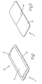
Figure 1 shows a topside view in perspective of a sealed single-dose break-open package in accordance with the present invention; -
Figure 2 shows an underside view in perspective of theFigure 1 package; -
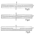
Figure 3 shows a lateral section, along an incision, of theFigure 1 package; -
Figures 4-8 show lateral sections, along an incision, of variations of theFigure 1 package; -
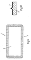
Figure 9 shows a plan view of a variation of theFigure 1 package; -
Figure 10 shows a cross section of a detail of theFigure 9 package; -
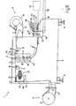
Figure 11 shows a schematic front view, with parts removed for clarity, of a packing machine, for producing theFigure 1 package; -
Figure 12 shows a schematic view in perspective, with parts removed for clarity, of a scoring station of theFigure 11 packing machine; -
Figure 13 shows a schematic front view, with parts removed for clarity, of theFigure 12 scoring station; -
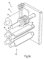
Figure 14 shows a schematic view in perspective, with parts removed for clarity, of a sealing station of theFigure 11 packing machine; -
Figure 15 shows a schematic front view, with parts removed for clarity, of theFigure 14 sealing station; -
Figure 16 shows a schematic side view, with parts removed for clarity, of theFigure 14 sealing station. - Number 1 in
Figures 1 and 2 indicates as a whole a sealed single-dose break-open package. Package 1 comprises arectangular sheet 2 of semirigid plastic material; and asheet 3 of flexible plastic material superimposed on and sealed tosheet 2 of semirigid plastic material to form a sealed pocket 4 containing a dose of a product 5 (liquid, cream, or powder). -
Sheet 2 of semirigid plastic material has acentral incision 6 extending crosswise tosheet 2 of semirigid plastic material (i.e. parallel to a short side ofsheet 2 of semirigid plastic material) to guide controlled breakage ofsheet 2 alongincision 6 and form an outlet forproduct 5 throughsheet 2. In other words, in actual use, to open package 1, the user simply grips package 1 with the fingers of one hand, and bends package 1 to breaksheet 2 of semirigid plastic material alongincision 6, so thatproduct 5 flows smoothly and hygienically out ofpackage 5, by not coming into contact with the outer surface of package 1 (i.e. sheet 2 of semirigid plastic material). - As shown in
Figures 3-8 ,incision 6 varies in depth lengthwise to breaksheet 2 of semirigid plastic material gradually alongincision 6. More specifically,incision 6 is deepest along a central portion ofincision 6. In other words, breakage ofsheet 2 of semirigid plastic material alongincision 6 is always gradual, i.e. proportional to the extent to which package 1 is bent, so that, when package 1 is bent relatively lightly,sheet 2 of semirigid plastic material only breaks along the central portion ofincision 6, and, as package 1 is bent further, breakage ofsheet 2 of semirigid plastic material also extends to the peripheral portions ofincision 6. - In
Figures 3 and7 ,incision 6 has a V-shaped cross section. - In
Figures 4 and8 ,incision 6 has a W-shaped cross section. - In
Figures 5 and6 ,incision 6 has a constant first depth along the peripheral portions, and a constant second depth, greater than the first depth, along the central portion. - In
Figures 3, 4 ,6 and 8 ,incision 6 is formed symmetrically on both sides ofsheet 2 of semirigid plastic material. Alternatively, inFigures 5 and7 ,incision 6 is only formed on one side ofsheet 2 of semirigid plastic material. - In a preferred non-limiting embodiment,
sheet 2 of semirigid plastic material is a laminate, and comprises an outer first supporting layer and an inner heat-sealable second layer (i.e. contacting sheet 3 of flexible plastic material). A further insulating or barrier layer may be provided between the supporting layer and the heat-sealable layer to ensure impermeability to air and/or light. - The supporting layer of
sheet 2 of semirigid plastic material may comprise one of the following materials: polystyrene (PS), polyvinyl chloride (PVC), acrylonitrile butadiene styrene (ABS), amorphous polyethylene terephthalate (APET), or polypropylene (PP), and is of a thickness ranging between 300 microns and 700 microns. - The heat-sealable layer of
sheet 2 of semirigid plastic may comprise one of the following material: polyethylene (PE) or polypropylene (PP), and is of a thickness ranging between 20 microns and 50 microns. - Table 1 below shows the possible material and thickness combinations of
sheet 2 of semirigid plastic material.TABLE 1 - Sheet 2 of semirigid plastic materialType of laminate Thickness (microns) PS - PE PS 300 ö 700 PE 20ö 50PS - PP PS 300 ö 700 PP 20ö 50PVC - PE PVC 300 ö 700 PE 20ö 50ABS - PE ABS 300 ö 700 PE 20ö 50APET - PE APET 300 ö 700 PE 20ö 50PP - PE PP 300 ö 700 PE 20ö 50 - In a preferred embodiment, the supporting layer of
sheet 2 of semirigid plastic material comprises 450-micron-thick polystyrene (PS), and the heat-sealable layer ofsheet 2 of semirigid plastic material comprises 35-micron-thick polyethylene (PE). In which case,sheet 2 of semirigid plastic material has a thickness of about 485 microns, a typical weight of about 500 g/m2, a typical break load of about 16 N/mm2, and a typical modulus of elasticity of about 2200 N/mm2. - In a preferred non-limiting embodiment,
sheet 3 of flexible plastic material comprises a laminate of two, three, or four layers. - The layers of
sheet 3 of flexible plastic material may comprise: polyethylene terephthalate (PET), polyethylene (PE), polyethylene with a barrier layer (PE BARRIER), metalized polyethylene terephthalate (PETM), aluminium (ALU), oriented polypropylene (OPP), oriented polyamide (OPA). - Table 2 below shows the possible material and thickness combinations of
sheet 3 of flexible plastic material.TABLE 2 - Sheet 3 of flexible plastic material1 Type of laminate Thickness (microns) PET - PE PET 12 ö 30 /PE 20 ö 150PET - PE BARRIERA PET 12 ö 30 /PE 30 ö 150PET BARRIERA - PE PET 12 ö 30 / PE 20 ö 150PET - PETM - PE PET 12 ö 30 / PETM 12ö 23 / PE 20 ö 150PET - ALU - PE PET 12 ö 30 / ALU 6ö 30 /PE 20 ö 150OPP - ALU - PE OPP 15 ö 3 / ALU 6ö 30 /PE 20 ö 150OPA - ALU - PE OPA 15 ö 30 /ALU 6ö 30 /PE 20 ö 150PET - ALU - PET - PE PET 12 ö 30 / ALU 6ö 30 /PE 20 ö 150PET - PET BARRIERA - PE PET 12 ö 30 / PET BARR 12ö 30 /PE 20 ö 150PET - ALU - OPA - PE PET 12 ö 30 / OPA 15ö 30 / ALU 6ö 30 /PE 20 ö 150 - In a preferred non-limiting embodiment, at the maximum depth of
incision 6,sheet 2 of semirigid plastic material is of a depth ranging between 75 and 150 microns, and, for example, of 100 microns; and the difference between the maximum and minimum depth ofincision 6 ranges between 50 and 150 microns, and is, for example, 100 microns. - In the embodiments shown in the attached drawings,
incision 6 is straight and parallel to the short side ofsheet 2 of semirigid plastic material. In other embodiments not shown,incision 6 may be shaped differently, e.g. may be curved (e.g. in the form of an arc of a circle or an arc of an ellipse), or may be V-shaped, U-shaped, or L-shaped. In other embodiments not shown,incision 6 may be inclined, i.e. may slope with respect to the sides ofsheet 2 of semirigid plastic material. - In one possible embodiment shown in
Figures 9 and 10 , the portions ofsheets sheet 3 of flexible plastic material). The knurling is defined by a number of ribs extending parallel to the short side of package 1. Each rib is typically 0.20 mm (more generally, 0.10 mm to 0.30 mm) in height, and has a triangular (i.e. inverted-V-shaped) cross section with a vertex angle of typically 60° (more generally, of 45° to 75°). The ribs are typically spaced 1.5 mm (more generally, 1 mm to 2 mm) apart. - It is important to note that the knurling on the parallel short sides of the portions of
sheets sheets - The knurling of the heat-sealed portions of
sheets - (particularly when pocket 4 contains a corrosive product 5).
- Package 1 as described above has numerous advantages : it is cheap and easy to produce, while at the same time enabling easy, intuitive control of the outflow of
product 5. More specifically, easy control of the outflow ofproduct 5 is achieved by virtue of the difference in thickness ofincision 6, which means breakage ofsheet 2 of semirigid plastic material is initially limited to the central portion ofincision 6, and only later extends along the rest ofincision 6. A small break insheet 2 of semirigid plastic material can thus be formed easily and intuitively to form a small outlet through whichproduct 5 flows slowly. Obviously, fast outflow ofproduct 5 can be achieved by simply increasing the size of the break insheet 2 of semirigid plastic material, i.e. increasing the size of the outlet, by simply bending package 1 further. - In other words, in package 1 described above, breakage of
sheet 2 of semirigid plastic material alongincision 6 is always gradual, i.e. proportional to the extent to which package 1 is bent, so that outflow ofproduct 5 can be regulated easily and intuitively by simply bending package 1 accordingly. -
Number 7 inFigure 11 indicates as a whole a packing machine for producing sealed single-dose packages 1 as described above and as shown inFigures 1 and 2 . -
Packing machine 7 comprises aframe 8, which rests on the floor on a number of supportingfeet 9, and supports two unwindingdevices device 10 supports areel 12, from which astrip 13 of semirigid plastic material is gradually unwound and fed to a formingstation 16; and unwindingdevice 11 supports areel 14, from which astrip 15 of flexible plastic material is unwound and also fed to formingstation 16. - A
powered traction device 17 between unwindingdevice 10 and formingstation 16 comprises two poweredrollers 18 for feedingstrip 13 of semirigid plastic material continuously to formingstation 16. And similarly, apowered traction device 19 between unwindingdevice 11 and formingstation 16 comprises two poweredrollers 20 for feedingstrip 15 of flexible plastic material continuously to formingstation 16. - Upstream from forming
station 16, a scoringdevice 21 scores strip 13 of semirigid plastic material transversely to form, alongstrip 13 of semirigid plastic material, a succession ofincisions 6. - In a preferred embodiment,
strip 13 of semirigid plastic material is fed continuously through scoringdevice 21. For which purpose, two tensioningfeed rollers 22 are provided upstream from scoringdevice 21, and are movable in opposition to elastic means to allow temporary stoppage ofstrip 13 of semirigid plastic material inside scoringdevice 21. Preferably, tensioningfeed rollers 22 are fitted to the opposite ends of a supportingarm 23 hinged to rotate freely about a central axis ofrotation 24; and one end of supportingarm 23 is connected to apneumatic cylinder 25, which pushes on supportingarm 23 to keepstrip 13 of semirigid plastic material taut. - As shown in
Figures 12 and 13 , scoringdevice 21 comprises two parallel, facing scoringplates 26, which are movable towards each other to gripstrip 13 of semirigid plastic material, and are fitted with respectiveinterchangeable scoring members 27. More specifically, scoringmember 27 of each scoringplate 26 is connected to scoringplate 26 by a dovetail joint and at least one screw. It is important to note that, depending on the form ofincision 6 to be made, both scoringmembers 27 may comprise sharp blades (not shown), or one scoringmember 27 may comprise a sharp blade, and the other scoringmember 27 may comprise a contrast surface. - In a preferred embodiment, scoring
device 21 comprises a fixedframe 28 supporting fourcylindrical guide members 29, which extend through respective throughholes 30 formed in scoringplates 26, so that scoringplates 26 slide alongguide members 29. Scoringdevice 21 also comprises two linear actuators 31 (typically, pneumatic or hydraulic cylinders) which push scoringplates 26 towards each other. - As shown in
Figures 11 ,14 ,15 and 16 , at formingstation 16,strip 13 of semirigid plastic material is superimposed onstrip 15 of flexible plastic material, and alongitudinal sealing device 32 seals the twostrips side tubes 33.Longitudinal sealing device 32 preferably comprises a cylindrical-section contrast roller 34; and three cylindrical-section, electricallyheated sealing rollers 35 fitted to acommon shaft 36.Sealing rollers 35 are preferably movable alongcommon shaft 36 to permit fast adjustment of the axial position of the rollers to the width ofstrips - At forming
station 16, ametering device 37 upstream fromlongitudinal sealing device 32 feeds a measure of a product inside eachtube 33 betweenstrip 13 of semirigid plastic material andstrip 15 of flexible plastic material. Atransverse sealing device 38 downstream frommetering device 37 seals the twostrips tube 33, a number of pockets 4 (Figure 1 ), each containing a dose of product.Metering device 37 preferably comprises twoproduct feed conduits 39, each having a vertical end portion which comes out betweenlongitudinal sealing device 32 andtransverse sealing device 38, and is located between sealingrollers 35 oflongitudinal sealing device 32. - A further
transverse sealing device 40 downstream fromtransverse sealing device 38 provides for further transverse sealing ofstrips transverse sealing device 38 forms a narrow preliminary transverse seal ofstrips transverse sealing device 40 forms a further, wide final transverse seal ofstrips transverse sealing device 38 only having to form a narrow preliminary transverse seal ofstrips tube 33. In other words,transverse sealing device 38 provides for simply forming a not necessarily strong or good-quality preliminary transverse seal ofstrips device 40 forms a final transverse seal ofstrips - In a preferred embodiment shown in the attached drawings, sealing
devices - In a preferred embodiment, the wide final transverse seal is 4 to 5 mm wide, and the narrow preliminary transverse seal is 1 to 3 mm wide. The wide final transverse seal is preferably about twice the width of the narrow preliminary transverse seal. For example, the wide final transverse seal is about 5 mm wide, and the narrow preliminary transverse seal is about 2.5 mm wide. The actual size of the transverse and longitudinal seals may obviously differ from those suggested above, depending on the characteristics of
strips - In a preferred embodiment, each
transverse sealing device section contrast roller 41; and an electricallyheated sealing roller 42 having an equilateral-triangular section and cooperating withcontrast roller 41. The vertices of each sealingroller 42 are bevelled (flattened) to form on sealingroller 42 three sealingsurfaces 43 at 120° with respect to one another. - A cutting
device 44 downstream from formingstation 16 cuts eachtube 33 transversely to separate sealed single-dose packages 1 successively. Preferably, cuttingdevice 44 punch-cuts eachtube 33 to separate sealed single-dose packages 1 successively. If necessary, cuttingdevice 44 also comprises a punch (not shown) for also perforating each sealed single-dose package 1 to form a through hole by which to hang sealed single-dose package 1. - Cutting
device 44 comprises a fixedframe 45; a fixedcontrast plate 46 fitted to frame 45; a cuttingplate 47 movable back and forth to and fromcontrast plate 46 and supporting a number of knives; and anactuator 48 for moving cuttingplate 47 back and forth to and fromcontrast plate 46. Fixedframe 45 supports fourcylindrical guide members 49 extending through respective through holes (not shown) in cuttingplate 47, so that cuttingplate 47 slides alongguide members 49.Actuator 48 preferably comprises a rotaryelectric motor 50, which moves cuttingplate 47 back and forth via a connectingrod 51. - Once detached from
tubes 33, sealed single-dose packages 1 drop by force of gravity onto anoutput belt conveyor 52 underneath cuttingdevice 44. Downstream from cuttingdevice 44, ashredding device 53 is preferably provided to shred the remains oftubes 33 once sealed single-dose packages 1 are separated; and the shredded remains oftubes 33 are collected in a bin (not shown) underneath shreddingdevice 53. - In a preferred embodiment, strips 13 and 15 are fed continuously through sealing
devices device 44. For which purpose, atraction device 54, having two powered step-operatedrollers 55, is provided between formingstation 16 and cuttingdevice 44. - In a preferred embodiment, strips 13 and 15 are preprinted, and have reference marks which are read by optical sensors to synchronize operation so that the printed areas are centred correctly on the finished sealed single-dose packages 1. The reference marks are preferably printed in the areas of
strips device 44, and so do not form part of the finished sealed single-dose packages 1. - A further embodiment comprises a heating device 56 (shown schematically by a dash line in
Figure 11 ) upstream from formingstation 16 to heat and increase the flexibility ofstrip 15 of flexible plastic material.Heating strip 15 of flexible plastic material beforehand temporarily increases the flexibility ofstrip 15 of flexible plastic material, so that a larger amount of product can be fed into pocket 4 to obtain a highly attractive sealed single-dose package 1. - To form the knurling shown in
Figures 9 and 10 , the outer surface of each sealingroller 35 has circumferential grooves, which are spaced apart with the same spacing as the knurling ribs, and negatively reproduce the shape of the knurling ribs; and the outer surface of at least sealingroller 42 oftransverse sealing device 40 has circumferential grooves, which are spaced apart with the same spacing as the knurling ribs, and negatively reproduce the shape of the knurling ribs. In one possible embodiment, only the outer surface of sealingroller 42 oftransverse sealing device 40 has circumferential grooves, while sealingroller 42 oftransverse sealing device 38 has no circumferential grooves. Alternatively, the outer surfaces of sealingrollers 42 of bothtransverse sealing devices -
Packing machine 7 described above has two side by side, parallel-operating production lines, but may obviously comprise a different number of side by side, parallel-operating production lines (e.g. one or three or four), depending on the output required. -
Packing machine 7 described above has numerous advantages : it is cheap and easy to produce, while at the same time producing sealed single-dose packages 1 of superior quality, with extremely strong transverse seals, and containing very little air.
Claims (15)
- A sealed single-dose break-open package (1) comprising:a first sheet (2) of semirigid plastic material;a second sheet (3) of flexible plastic material superimposed on and sealed to the first sheet (2) of semirigid plastic material to define a sealed pocket (4) containing a dose of a product (5); andan incision (6) formed in the first sheet (2) of semirigid plastic material to guide controlled breakage of the first sheet (2) along the incision (6) and form an outlet opening for the product (5) through the first sheet (2);the sealed single-dose package (1) being characterized in that the incision (6) varies in depth lengthwise to break the first sheet (2) gradually along the incision (6).
- A sealed single-dose package (1) as claimed in Claim 1, wherein the incision (6) is of maximum depth along a central portion of the incision (6).
- A sealed single-dose package (1) as claimed in Claim 2, wherein the incision (6) has a V-shaped cross section.
- A sealed single-dose package (1) as claimed in Claim 2, wherein the incision (6) has a W-shaped cross section.
- A sealed single-dose package (1) as claimed in Claim 2, wherein the incision (6) has a constant first depth along peripheral portions, and a constant second depth, greater than the first depth, along the central portion.
- A sealed single-dose package (1) as claimed in one of Claims 1 to 5, wherein, at the maximum depth of the incision (6), the first sheet (2) of semirigid plastic material has a thickness ranging between 75 and 150 microns.
- A sealed single-dose package (1) as claimed in Claim 6, wherein, at the maximum depth of the incision (6), the first sheet (2) of semirigid plastic material has a thickness of 100 microns.
- A sealed single-dose package (1) as claimed in one of Claims 1 to 7, wherein the difference between the maximum depth of the incision (6) and the minimum depth of the incision (6) ranges between 50 and 150 microns.
- A sealed single-dose package (1) as claimed in Claim 8, wherein the difference between the maximum depth of the incision (6) and the minimum depth of the incision (6) is 100 microns.
- A sealed single-dose package (1) as claimed in one of Claims 1 to 9, wherein:the first sheet (2) of semirigid plastic material is defined by a laminate comprising a first outer supporting
layer and a second inner heat-sealable layer;
a further insulating or barrier layer is provided between the supporting layer and the heat-sealable layer;
the supporting layer of the first sheet (2) of semirigid plastic material comprises one of the following materials: polystyrene (PS), polyvinyl chloride (PVC), acrylonitrile butadiene styrene (ABS), amorphous polyethylene terephthalate (APET), polypropylene (PP); and
the heat-sealable layer of the first sheet (2) of semirigid plastic material comprises one of the following materials: polyethylene (PE) or polypropylene (PP). - A sealed single-dose package (1) as claimed in one of Claims 1 to 10, wherein the second sheet (3) of flexible plastic material is laminated; and the layers of the second sheet (3) of flexible plastic material may comprise: polyethylene terephthalate (PET), polyethylene (PE), polyethylene with a barrier layer (PE BARRIER), metalized polyethylene terephthalate (PETM), aluminium (ALU), oriented polypropylene (OPP), oriented polyamide (OPA).
- A sealed single-dose package (1) as claimed in one of Claims 1 to 11, wherein the portions of the first and second sheet (3, 4) surrounding the pocket (4) and sealed to each other are knurled.
- A sealed single-dose package (1) as claimed in Claim 12, wherein the knurling is formed on the topside of the second sheet (3) of flexible plastic material.
- A sealed single-dose package (1) as claimed in Claim 12 or 13, wherein the knurling is defined by a number of ribs extending parallel to the short side of the package (1).
- A sealed single-dose package (1) as claimed in Claim 14, wherein:each rib is of a height ranging between 0.10 mm and 0.30 mm;the ribs are spaced 1 mm to 2 mm apart; andeach rib has a triangular cross section with a vertex angle ranging between 45° and 75°.
Priority Applications (1)
| Application Number | Priority Date | Filing Date | Title |
|---|---|---|---|
| PL07734593T PL2076451T3 (en) | 2006-09-28 | 2007-05-18 | Sealed single-dose break-open package |
Applications Claiming Priority (4)
| Application Number | Priority Date | Filing Date | Title |
|---|---|---|---|
| ITBO20060666 ITBO20060666A1 (en) | 2006-09-28 | 2006-09-28 | PACKAGING AND PACKAGING MACHINE TO CREATE A SINGLE PACKAGE WITH BREAKING OPENING |
| IT000665A ITBO20060665A1 (en) | 2006-09-28 | 2006-09-28 | SINGLE-DOSE SEALED PACKAGE WITH BREAK OPENING |
| ITBO20070083 ITBO20070083A1 (en) | 2007-02-14 | 2007-02-14 | SINGLE-DOSE SEALED PACKAGE WITH BREAK OPENING |
| PCT/IB2007/001285 WO2008038074A2 (en) | 2006-09-28 | 2007-05-18 | Sealed single-dose break-open package, and packing method and machine for producing a single-dose break-open package |
Publications (2)
| Publication Number | Publication Date |
|---|---|
| EP2076451A2 EP2076451A2 (en) | 2009-07-08 |
| EP2076451B1 true EP2076451B1 (en) | 2010-06-30 |
Family
ID=38670021
Family Applications (1)
| Application Number | Title | Priority Date | Filing Date |
|---|---|---|---|
| EP07734593A Active EP2076451B1 (en) | 2006-09-28 | 2007-05-18 | Sealed single-dose break-open package |
Country Status (14)
| Country | Link |
|---|---|
| US (1) | US8069985B2 (en) |
| EP (1) | EP2076451B1 (en) |
| JP (1) | JP5244111B2 (en) |
| KR (1) | KR101348326B1 (en) |
| AT (1) | ATE472490T1 (en) |
| AU (1) | AU2007301633B2 (en) |
| BR (1) | BRPI0715256B1 (en) |
| DE (1) | DE602007007507D1 (en) |
| ES (1) | ES2346809T3 (en) |
| NZ (1) | NZ576441A (en) |
| PL (1) | PL2076451T3 (en) |
| PT (1) | PT2076451E (en) |
| WO (1) | WO2008038074A2 (en) |
| ZA (1) | ZA200902794B (en) |
Families Citing this family (40)
| Publication number | Priority date | Publication date | Assignee | Title |
|---|---|---|---|---|
| ES2351237T3 (en) | 2007-09-17 | 2011-02-01 | The Tapemark Company | DISTRIBUTION CONTAINER WITH APPLICATOR. |
| US8028837B2 (en) | 2008-12-18 | 2011-10-04 | Kimberly-Clark Worldwide, Inc. | Break-open package with shaped die cut for storing and dispensing substrates |
| ITMO20090004A1 (en) | 2009-01-13 | 2010-07-14 | Paolo Mesini | PACKAGING MACHINE FOR THE PRODUCTION OF SINGLE-DOSE PACKAGES WITH BREAKING OPENING |
| MX2012008263A (en) * | 2010-01-14 | 2012-08-03 | Procter & Gamble | Method for treating a stained fabric. |
| CA2690279C (en) | 2010-01-14 | 2013-11-12 | The Procter & Gamble Company | Apparatus for treating a stain in clothing |
| US8425136B2 (en) * | 2010-01-14 | 2013-04-23 | The Procter & Gamble Company | Apparatus for treating a stain in clothing |
| CA2690296C (en) | 2010-01-14 | 2014-07-22 | The Procter & Gamble Company | Apparatus for treating a stain in clothing |
| US20120304600A1 (en) * | 2011-05-31 | 2012-12-06 | Ward Kraft, Inc. | Containment Device And Method Of Use |
| ITMO20110258A1 (en) * | 2011-10-11 | 2013-04-12 | Mepar Societa A Responsabilita Li Mitata | SINGLE-DOSE SEALED PACKAGE WITH BREAKING OPENING AND METHOD FOR THE CREATION OF A SINGLE-DOSE SEALED PACKAGE WITH BREAKING OPENING |
| ITBO20120080A1 (en) | 2012-02-20 | 2013-08-21 | Diapack Ltd | SINGLE-DOSE SEALED PACKAGE WITH BREAKING OPENING AND PROVIDING INVITATION |
| CN102717922B (en) * | 2012-07-06 | 2013-12-04 | 柳真 | Flexible automatic packing production line for inflammables and explosives |
| US9327044B2 (en) * | 2013-01-25 | 2016-05-03 | The Procter & Gamble Company | Method for delivering a volatile fluid to the atmosphere |
| US9327043B2 (en) * | 2013-01-25 | 2016-05-03 | The Procter & Gamble Company | Device for delivering a volatile fluid to the atmosphere |
| CA2915926A1 (en) | 2013-06-17 | 2014-12-24 | Zobele Holding Spa | Container |
| CN105764809B (en) * | 2013-11-12 | 2018-09-04 | 高露洁-棕榄公司 | The oral care implement of packaging and its deployment method |
| BR112016009968A2 (en) * | 2013-11-12 | 2017-10-10 | Colgate Palmolive Co | packaged oral hygiene implement and opening method |
| EP2944579B1 (en) | 2014-04-22 | 2017-03-22 | Easysnap Technology S.r.l. | Incision unit to manufacture a single-dose break-open package |
| US10131479B2 (en) | 2014-04-30 | 2018-11-20 | Easysnap Technology S.R.L. | Sealed single-dose break-open package suited to be opened vertically |
| US20150335586A1 (en) | 2014-05-20 | 2015-11-26 | R.P. Scherer Technologies, Llc | Capsule dispensing container |
| CN107405418A (en) * | 2015-03-19 | 2017-11-28 | 约翰逊父子公司 | Composite membrane |
| WO2016210342A1 (en) | 2015-06-26 | 2016-12-29 | C.R. Bard, Inc. | Topical substance application device including applicator |
| US10793813B2 (en) | 2016-05-06 | 2020-10-06 | Gpcp Ip Holdings Llc | Dispersible packaging for toilet paper moistener product |
| BR112018006447B1 (en) | 2016-08-03 | 2022-11-01 | Future Labo Co., Ltd | FLEX-OPEN PACKAGING, METHOD FOR MANUFACTURING FLEX-OPEN PACKAGING |
| JP7416717B2 (en) * | 2018-01-09 | 2024-01-17 | ブイ-シェイプス エス.アール.エル. | Sealed single-dose break-open package and manufacturing method thereof |
| IT201700149752A1 (en) * | 2018-01-09 | 2019-07-09 | V Shapes S R L | SINGLE-DOSE SEALED PACKAGING WITH BREAK-OPENING AND RELATIVE PRODUCTION METHOD |
| IT201700149766A1 (en) * | 2018-01-09 | 2019-07-09 | V Shapes S R L | SINGLE-DOSE SEALED PACKAGING WITH BREAK-OPENING AND RELATIVE PRODUCTION METHOD |
| IT201800003287A1 (en) * | 2018-03-05 | 2019-09-05 | V Shapes S R L | ENGRAVING STATION FOR PACKAGING MACHINE AND RELATIVE ENGRAVING METHOD |
| IT201800003352A1 (en) * | 2018-03-07 | 2019-09-07 | Easysnap Tech S R L | SEALED PACKAGING WITH BREAK-OPENING IN A CORNER |
| US10800587B2 (en) | 2018-06-29 | 2020-10-13 | Henkel IP & Holding GmbH | Separatable agent doses |
| IT201900009036A1 (en) | 2019-06-14 | 2020-12-14 | V Shapes S R L | SINGLE-DOSE SEALED PACKAGING WITH BREAK-OPENING, DEVICE AND METHOD OF CONSTRUCTION |
| IT201900019854A1 (en) * | 2019-10-28 | 2021-04-28 | Guala Pack Spa | DISPOSABLE PACKAGING WITH BREAK-OPENING |
| KR20210094384A (en) | 2020-01-21 | 2021-07-29 | 삼성전자주식회사 | Apparatus and method for measuring in-situ crosslink density and crosslinked product and method of forming the same |
| IT202100000578A1 (en) | 2021-01-14 | 2022-07-14 | Noople S R L | SINGLE-DOSE SEALED PACK WITH MULTILAYER SHEET. |
| IT202100003137A1 (en) | 2021-02-12 | 2022-08-12 | V Shapes S R L | ENGRAVING UNIT, ENGRAVING METHOD AND PACKAGING EQUIPMENT |
| IT202100003449A1 (en) | 2021-02-16 | 2022-08-16 | V Shapes S R L | PACKAGING EQUIPMENT WITH TREATMENT UNIT AND METHOD FOR THE PRODUCTION OF A SINGLE-DOSE SEALED PACK |
| IT202100004106A1 (en) | 2021-02-23 | 2022-08-23 | V Shapes S R L | PRINTING UNIT FOR PACKAGING EQUIPMENT, APPARATUS AND METHOD FOR THE PRODUCTION OF A SINGLE-DOSE SEALED PACK. |
| US11542460B2 (en) | 2021-04-14 | 2023-01-03 | Henkel Ag & Co. Kgaa | Multi-chamber detergent single dose packs with detachable and reattachable functionality and methods of using the same |
| IT202100010379A1 (en) | 2021-04-23 | 2022-10-23 | Easysnap Tech S R L | SINGLE-DOSE SEALED PACKAGE WITH BREAK OPENING |
| IT202100017756A1 (en) | 2021-07-06 | 2023-01-06 | Easysnap Tech S R L | METHOD FOR CREATING A SINGLE-DOSE SEALED PACK WITH RIP OPENING |
| KR102362291B1 (en) * | 2021-07-28 | 2022-02-14 | 주식회사 명성에이앤티 | Liquid storage package with incision line formed |
Family Cites Families (16)
| Publication number | Priority date | Publication date | Assignee | Title |
|---|---|---|---|---|
| US2215705A (en) * | 1938-05-31 | 1940-09-24 | Mid West Bottle Cap Co | Bottle cap package |
| FR73761E (en) * | 1958-06-20 | 1960-09-05 | Seab | Automatic machine for packaging liquid or other products |
| US3075684A (en) * | 1961-01-30 | 1963-01-29 | Gen Foods Corp | Easy to open carton |
| FR1476746A (en) * | 1966-02-26 | 1967-04-14 | Azolacq Soc Chimique D Engrais | Automatic bagging process and machine |
| US3472368A (en) * | 1968-10-04 | 1969-10-14 | Harold R Hellstrom | Quick-opening blister packets |
| US4236652A (en) * | 1979-03-20 | 1980-12-02 | American Can Company | Dispenser package |
| US4762230A (en) * | 1986-10-08 | 1988-08-09 | Warner-Lambert Company | Tear oriented package |
| AU1208192A (en) * | 1991-05-21 | 1992-12-30 | Ary S. Chernomorsky | Condom package |
| DK170039B1 (en) * | 1993-03-26 | 1995-05-08 | Soeren Moesmann | A package, especially a bag of flexible material with an opener |
| DE69620644T2 (en) * | 1995-08-04 | 2002-08-08 | Thornton Investmments Ltd., Sydenham | TACKABLE BAG |
| AU779865B2 (en) | 1999-12-14 | 2005-02-17 | Flexi-Pac (Proprietary) Limited | Containers and method for manufacturing containers |
| US6863960B2 (en) * | 1999-12-21 | 2005-03-08 | The Procter & Gamble Company | User-activatible substance delivery system |
| JP4610045B2 (en) | 2000-05-23 | 2011-01-12 | 株式会社ディスペンパックジャパン | Half-cut forming device |
| JP2002284238A (en) * | 2001-03-28 | 2002-10-03 | Deisupenpakku Japan:Kk | Package |
| JP2003321062A (en) * | 2002-04-26 | 2003-11-11 | Tendou Seiyaku Kk | Packaging body and method for packaging article |
| US7506762B2 (en) * | 2003-12-02 | 2009-03-24 | The Tapemark Company | Dispensing package |
-
2007
- 2007-05-18 JP JP2009529785A patent/JP5244111B2/en active Active
- 2007-05-18 AT AT07734593T patent/ATE472490T1/en active
- 2007-05-18 NZ NZ576441A patent/NZ576441A/en unknown
- 2007-05-18 EP EP07734593A patent/EP2076451B1/en active Active
- 2007-05-18 AU AU2007301633A patent/AU2007301633B2/en active Active
- 2007-05-18 US US11/913,737 patent/US8069985B2/en active Active
- 2007-05-18 PL PL07734593T patent/PL2076451T3/en unknown
- 2007-05-18 WO PCT/IB2007/001285 patent/WO2008038074A2/en active Application Filing
- 2007-05-18 BR BRPI0715256A patent/BRPI0715256B1/en active IP Right Grant
- 2007-05-18 ES ES07734593T patent/ES2346809T3/en active Active
- 2007-05-18 KR KR1020097008640A patent/KR101348326B1/en active IP Right Grant
- 2007-05-18 DE DE602007007507T patent/DE602007007507D1/de active Active
- 2007-05-18 PT PT07734593T patent/PT2076451E/en unknown
-
2009
- 2009-04-23 ZA ZA2009/02794A patent/ZA200902794B/en unknown
Also Published As
| Publication number | Publication date |
|---|---|
| AU2007301633A1 (en) | 2008-04-03 |
| US20100059402A1 (en) | 2010-03-11 |
| EP2076451A2 (en) | 2009-07-08 |
| ES2346809T3 (en) | 2010-10-20 |
| JP5244111B2 (en) | 2013-07-24 |
| KR20090089290A (en) | 2009-08-21 |
| BRPI0715256B1 (en) | 2018-12-04 |
| WO2008038074A2 (en) | 2008-04-03 |
| PT2076451E (en) | 2010-11-03 |
| BRPI0715256A8 (en) | 2017-10-03 |
| ATE472490T1 (en) | 2010-07-15 |
| KR101348326B1 (en) | 2014-01-06 |
| AU2007301633B2 (en) | 2012-03-08 |
| US8069985B2 (en) | 2011-12-06 |
| PL2076451T3 (en) | 2010-12-31 |
| NZ576441A (en) | 2010-12-24 |
| DE602007007507D1 (en) | 2010-08-12 |
| WO2008038074A3 (en) | 2008-06-26 |
| AU2007301633A2 (en) | 2009-06-25 |
| WO2008038074A8 (en) | 2008-08-21 |
| JP2010504888A (en) | 2010-02-18 |
| ZA200902794B (en) | 2010-02-24 |
| BRPI0715256A2 (en) | 2012-12-25 |
Similar Documents
| Publication | Publication Date | Title |
|---|---|---|
| EP2076451B1 (en) | Sealed single-dose break-open package | |
| CA2534025C (en) | Packaging machine for producing tubular bags and the thus produced tubular bags | |
| EP2853496B1 (en) | Drug dividing and packaging device | |
| CN101568477B (en) | Sealed single-dose break-open package | |
| WO2013054169A1 (en) | Single-dose sealed pack with break opening and method for the manufacture of a single-dose sealed pack with break opening | |
| US8739504B2 (en) | Packaging method and apparatus | |
| CA3086965C (en) | Apparatus and method for producing a sealed single-dose break-open package | |
| CA2603147C (en) | Sealed single-dose break-open package, and packing method and machine for producing a single-dose break-open package | |
| JP2022520064A (en) | Equipment and methods for producing tubular packaging | |
| KR101132725B1 (en) | A cutting line processing apparatus of packing bag and the packing bag thereby | |
| RU2427516C2 (en) | Sealed throw-away one-portion container | |
| JP2010285181A (en) | Wind-packaging machine | |
| WO2022091155A1 (en) | Cutting unit for making single-dose packages | |
| EP1882581B1 (en) | A method of applying tear tapes to a packaging material, a method of packaging coffee, a device for applying tear tapes to a packaging material and a packaging machine for packaging coffee | |
| EP1166980B1 (en) | A process for cutting flat sheets for making wrappers for a pasty product | |
| AU2012219023B2 (en) | Envelope manufacturing process | |
| CN116157334A (en) | Method and machine for manufacturing packages | |
| NZ614332B2 (en) | Envelope manufacturing process | |
| TWM338662U (en) | Patch-manufacturing packing machine |
Legal Events
| Date | Code | Title | Description |
|---|---|---|---|
| PUAI | Public reference made under article 153(3) epc to a published international application that has entered the european phase |
Free format text: ORIGINAL CODE: 0009012 |
|
| 17P | Request for examination filed |
Effective date: 20090331 |
|
| AK | Designated contracting states |
Kind code of ref document: A2 Designated state(s): AT BE BG CH CY CZ DE DK EE ES FI FR GB GR HU IE IS IT LI LT LU LV MC MT NL PL PT RO SE SI SK TR |
|
| AX | Request for extension of the european patent |
Extension state: AL BA HR MK RS |
|
| GRAP | Despatch of communication of intention to grant a patent |
Free format text: ORIGINAL CODE: EPIDOSNIGR1 |
|
| RTI1 | Title (correction) |
Free format text: SEALED SINGLE-DOSE BREAK-OPEN PACKAGE |
|
| DAX | Request for extension of the european patent (deleted) | ||
| GRAS | Grant fee paid |
Free format text: ORIGINAL CODE: EPIDOSNIGR3 |
|
| TPAC | Observations filed by third parties |
Free format text: ORIGINAL CODE: EPIDOSNTIPA |
|
| GRAA | (expected) grant |
Free format text: ORIGINAL CODE: 0009210 |
|
| AK | Designated contracting states |
Kind code of ref document: B1 Designated state(s): AT BE BG CH CY CZ DE DK EE ES FI FR GB GR HU IE IS IT LI LT LU LV MC MT NL PL PT RO SE SI SK TR |
|
| REG | Reference to a national code |
Ref country code: CH Ref legal event code: EP Ref country code: GB Ref legal event code: FG4D |
|
| REG | Reference to a national code |
Ref country code: IE Ref legal event code: FG4D |
|
| REF | Corresponds to: |
Ref document number: 602007007507 Country of ref document: DE Date of ref document: 20100812 Kind code of ref document: P |
|
| REG | Reference to a national code |
Ref country code: NL Ref legal event code: T3 |
|
| REG | Reference to a national code |
Ref country code: RO Ref legal event code: EPE |
|
| REG | Reference to a national code |
Ref country code: CH Ref legal event code: NV Representative=s name: HEPP WENGER RYFFEL AG |
|
| REG | Reference to a national code |
Ref country code: ES Ref legal event code: FG2A Ref document number: 2346809 Country of ref document: ES Kind code of ref document: T3 |
|
| PG25 | Lapsed in a contracting state [announced via postgrant information from national office to epo] |
Ref country code: LT Free format text: LAPSE BECAUSE OF FAILURE TO SUBMIT A TRANSLATION OF THE DESCRIPTION OR TO PAY THE FEE WITHIN THE PRESCRIBED TIME-LIMIT Effective date: 20100630 Ref country code: SE Free format text: LAPSE BECAUSE OF FAILURE TO SUBMIT A TRANSLATION OF THE DESCRIPTION OR TO PAY THE FEE WITHIN THE PRESCRIBED TIME-LIMIT Effective date: 20100630 |
|
| REG | Reference to a national code |
Ref country code: PT Ref legal event code: SC4A Free format text: AVAILABILITY OF NATIONAL TRANSLATION Effective date: 20100929 |
|
| LTIE | Lt: invalidation of european patent or patent extension |
Effective date: 20100630 |
|
| PG25 | Lapsed in a contracting state [announced via postgrant information from national office to epo] |
Ref country code: SI Free format text: LAPSE BECAUSE OF FAILURE TO SUBMIT A TRANSLATION OF THE DESCRIPTION OR TO PAY THE FEE WITHIN THE PRESCRIBED TIME-LIMIT Effective date: 20100630 Ref country code: FI Free format text: LAPSE BECAUSE OF FAILURE TO SUBMIT A TRANSLATION OF THE DESCRIPTION OR TO PAY THE FEE WITHIN THE PRESCRIBED TIME-LIMIT Effective date: 20100630 Ref country code: LV Free format text: LAPSE BECAUSE OF FAILURE TO SUBMIT A TRANSLATION OF THE DESCRIPTION OR TO PAY THE FEE WITHIN THE PRESCRIBED TIME-LIMIT Effective date: 20100630 |
|
| REG | Reference to a national code |
Ref country code: PL Ref legal event code: T3 |
|
| PG25 | Lapsed in a contracting state [announced via postgrant information from national office to epo] |
Ref country code: EE Free format text: LAPSE BECAUSE OF FAILURE TO SUBMIT A TRANSLATION OF THE DESCRIPTION OR TO PAY THE FEE WITHIN THE PRESCRIBED TIME-LIMIT Effective date: 20100630 |
|
| PG25 | Lapsed in a contracting state [announced via postgrant information from national office to epo] |
Ref country code: SK Free format text: LAPSE BECAUSE OF FAILURE TO SUBMIT A TRANSLATION OF THE DESCRIPTION OR TO PAY THE FEE WITHIN THE PRESCRIBED TIME-LIMIT Effective date: 20100630 Ref country code: CY Free format text: LAPSE BECAUSE OF FAILURE TO SUBMIT A TRANSLATION OF THE DESCRIPTION OR TO PAY THE FEE WITHIN THE PRESCRIBED TIME-LIMIT Effective date: 20100630 Ref country code: IS Free format text: LAPSE BECAUSE OF FAILURE TO SUBMIT A TRANSLATION OF THE DESCRIPTION OR TO PAY THE FEE WITHIN THE PRESCRIBED TIME-LIMIT Effective date: 20101030 |
|
| PG25 | Lapsed in a contracting state [announced via postgrant information from national office to epo] |
Ref country code: DK Free format text: LAPSE BECAUSE OF FAILURE TO SUBMIT A TRANSLATION OF THE DESCRIPTION OR TO PAY THE FEE WITHIN THE PRESCRIBED TIME-LIMIT Effective date: 20100630 |
|
| PLBE | No opposition filed within time limit |
Free format text: ORIGINAL CODE: 0009261 |
|
| STAA | Information on the status of an ep patent application or granted ep patent |
Free format text: STATUS: NO OPPOSITION FILED WITHIN TIME LIMIT |
|
| PG25 | Lapsed in a contracting state [announced via postgrant information from national office to epo] |
Ref country code: GR Free format text: LAPSE BECAUSE OF FAILURE TO SUBMIT A TRANSLATION OF THE DESCRIPTION OR TO PAY THE FEE WITHIN THE PRESCRIBED TIME-LIMIT Effective date: 20101001 |
|
| 26N | No opposition filed |
Effective date: 20110331 |
|
| REG | Reference to a national code |
Ref country code: DE Ref legal event code: R097 Ref document number: 602007007507 Country of ref document: DE Effective date: 20110330 |
|
| PG25 | Lapsed in a contracting state [announced via postgrant information from national office to epo] |
Ref country code: MC Free format text: LAPSE BECAUSE OF NON-PAYMENT OF DUE FEES Effective date: 20110531 Ref country code: MT Free format text: LAPSE BECAUSE OF FAILURE TO SUBMIT A TRANSLATION OF THE DESCRIPTION OR TO PAY THE FEE WITHIN THE PRESCRIBED TIME-LIMIT Effective date: 20100630 |
|
| REG | Reference to a national code |
Ref country code: IE Ref legal event code: MM4A |
|
| PG25 | Lapsed in a contracting state [announced via postgrant information from national office to epo] |
Ref country code: IE Free format text: LAPSE BECAUSE OF NON-PAYMENT OF DUE FEES Effective date: 20110518 |
|
| PG25 | Lapsed in a contracting state [announced via postgrant information from national office to epo] |
Ref country code: LU Free format text: LAPSE BECAUSE OF NON-PAYMENT OF DUE FEES Effective date: 20110518 |
|
| PG25 | Lapsed in a contracting state [announced via postgrant information from national office to epo] |
Ref country code: BG Free format text: LAPSE BECAUSE OF FAILURE TO SUBMIT A TRANSLATION OF THE DESCRIPTION OR TO PAY THE FEE WITHIN THE PRESCRIBED TIME-LIMIT Effective date: 20100930 Ref country code: TR Free format text: LAPSE BECAUSE OF FAILURE TO SUBMIT A TRANSLATION OF THE DESCRIPTION OR TO PAY THE FEE WITHIN THE PRESCRIBED TIME-LIMIT Effective date: 20100630 |
|
| PG25 | Lapsed in a contracting state [announced via postgrant information from national office to epo] |
Ref country code: HU Free format text: LAPSE BECAUSE OF FAILURE TO SUBMIT A TRANSLATION OF THE DESCRIPTION OR TO PAY THE FEE WITHIN THE PRESCRIBED TIME-LIMIT Effective date: 20100630 |
|
| REG | Reference to a national code |
Ref country code: FR Ref legal event code: PLFP Year of fee payment: 10 |
|
| REG | Reference to a national code |
Ref country code: CH Ref legal event code: PUE Owner name: EASYSNAP TECHNOLOGY S.R.L., IT Free format text: FORMER OWNER: DIAPACK LIMITED, GB |
|
| REG | Reference to a national code |
Ref country code: DE Ref legal event code: R082 Ref document number: 602007007507 Country of ref document: DE Representative=s name: WEBER & HEIM PATENTANWAELTE PARTNERSCHAFTSGESE, DE Ref country code: DE Ref legal event code: R082 Ref document number: 602007007507 Country of ref document: DE Representative=s name: WUNDERLICH & HEIM PATENTANWAELTE PARTNERSCHAFT, DE Ref country code: DE Ref legal event code: R081 Ref document number: 602007007507 Country of ref document: DE Owner name: EASYSNAP TECHNOLOGY S.R.L., IT Free format text: FORMER OWNER: DIAPACK LTD., LONDON, GB |
|
| REG | Reference to a national code |
Ref country code: NL Ref legal event code: PD Owner name: EASYSNAP TECHNOLOGY S.R.L.; IT Free format text: DETAILS ASSIGNMENT: CHANGE OF OWNER(S), ASSIGNMENT; FORMER OWNER NAME: DIAPACK LIMITED Effective date: 20170222 |
|
| REG | Reference to a national code |
Ref country code: ES Ref legal event code: PC2A Owner name: EASYSNAP TECHNOLOGIES S.R.L. Effective date: 20170410 |
|
| REG | Reference to a national code |
Ref country code: AT Ref legal event code: PC Ref document number: 472490 Country of ref document: AT Kind code of ref document: T Owner name: EASYSNAP TECHNOLOGY S.R.L., IT Effective date: 20170411 |
|
| REG | Reference to a national code |
Ref country code: GB Ref legal event code: 732E Free format text: REGISTERED BETWEEN 20170427 AND 20170503 |
|
| REG | Reference to a national code |
Ref country code: FR Ref legal event code: PLFP Year of fee payment: 11 |
|
| REG | Reference to a national code |
Ref country code: FR Ref legal event code: TP Owner name: EASYSNAP TECHNOLOGY S.R.L., IT Effective date: 20170821 |
|
| REG | Reference to a national code |
Ref country code: DE Ref legal event code: R082 Ref document number: 602007007507 Country of ref document: DE Representative=s name: WUNDERLICH & HEIM PATENTANWAELTE PARTNERSCHAFT, DE |
|
| REG | Reference to a national code |
Ref country code: FR Ref legal event code: PLFP Year of fee payment: 12 |
|
| PGFP | Annual fee paid to national office [announced via postgrant information from national office to epo] |
Ref country code: CZ Payment date: 20220324 Year of fee payment: 16 |
|
| PGFP | Annual fee paid to national office [announced via postgrant information from national office to epo] |
Ref country code: NL Payment date: 20220519 Year of fee payment: 16 |
|
| PGFP | Annual fee paid to national office [announced via postgrant information from national office to epo] |
Ref country code: RO Payment date: 20220512 Year of fee payment: 16 Ref country code: PT Payment date: 20220505 Year of fee payment: 16 |
|
| PGFP | Annual fee paid to national office [announced via postgrant information from national office to epo] |
Ref country code: CH Payment date: 20220519 Year of fee payment: 16 Ref country code: BE Payment date: 20220519 Year of fee payment: 16 Ref country code: AT Payment date: 20220523 Year of fee payment: 16 |
|
| P01 | Opt-out of the competence of the unified patent court (upc) registered |
Effective date: 20230526 |
|
| REG | Reference to a national code |
Ref country code: CH Ref legal event code: PL |
|
| REG | Reference to a national code |
Ref country code: NL Ref legal event code: MM Effective date: 20230601 |
|
| REG | Reference to a national code |
Ref country code: AT Ref legal event code: MM01 Ref document number: 472490 Country of ref document: AT Kind code of ref document: T Effective date: 20230518 |
|
| REG | Reference to a national code |
Ref country code: BE Ref legal event code: MM Effective date: 20230531 |
|
| PG25 | Lapsed in a contracting state [announced via postgrant information from national office to epo] |
Ref country code: RO Free format text: LAPSE BECAUSE OF NON-PAYMENT OF DUE FEES Effective date: 20230518 Ref country code: PT Free format text: LAPSE BECAUSE OF NON-PAYMENT OF DUE FEES Effective date: 20231120 Ref country code: LI Free format text: LAPSE BECAUSE OF NON-PAYMENT OF DUE FEES Effective date: 20230531 Ref country code: CZ Free format text: LAPSE BECAUSE OF NON-PAYMENT OF DUE FEES Effective date: 20230518 Ref country code: CH Free format text: LAPSE BECAUSE OF NON-PAYMENT OF DUE FEES Effective date: 20230531 Ref country code: AT Free format text: LAPSE BECAUSE OF NON-PAYMENT OF DUE FEES Effective date: 20230518 |
|
| PG25 | Lapsed in a contracting state [announced via postgrant information from national office to epo] |
Ref country code: NL Free format text: LAPSE BECAUSE OF NON-PAYMENT OF DUE FEES Effective date: 20230601 |
|
| PG25 | Lapsed in a contracting state [announced via postgrant information from national office to epo] |
Ref country code: BE Free format text: LAPSE BECAUSE OF NON-PAYMENT OF DUE FEES Effective date: 20230531 |
|
| PGFP | Annual fee paid to national office [announced via postgrant information from national office to epo] |
Ref country code: PL Payment date: 20240322 Year of fee payment: 18 Ref country code: IT Payment date: 20240305 Year of fee payment: 18 |
|
| PGFP | Annual fee paid to national office [announced via postgrant information from national office to epo] |
Ref country code: GB Payment date: 20240521 Year of fee payment: 18 |
|
| PGFP | Annual fee paid to national office [announced via postgrant information from national office to epo] |
Ref country code: DE Payment date: 20240521 Year of fee payment: 18 |
|
| PGFP | Annual fee paid to national office [announced via postgrant information from national office to epo] |
Ref country code: ES Payment date: 20240603 Year of fee payment: 18 |
|
| PGFP | Annual fee paid to national office [announced via postgrant information from national office to epo] |
Ref country code: FR Payment date: 20240423 Year of fee payment: 18 |