EP2075472B1 - Lüfterbaugruppe - Google Patents
Lüfterbaugruppe Download PDFInfo
- Publication number
- EP2075472B1 EP2075472B1 EP08170943.8A EP08170943A EP2075472B1 EP 2075472 B1 EP2075472 B1 EP 2075472B1 EP 08170943 A EP08170943 A EP 08170943A EP 2075472 B1 EP2075472 B1 EP 2075472B1
- Authority
- EP
- European Patent Office
- Prior art keywords
- shroud
- fan
- coupling
- vibration preventing
- machine room
- Prior art date
- Legal status (The legal status is an assumption and is not a legal conclusion. Google has not performed a legal analysis and makes no representation as to the accuracy of the status listed.)
- Active
Links
- 230000008878 coupling Effects 0.000 claims description 71
- 238000010168 coupling process Methods 0.000 claims description 71
- 238000005859 coupling reaction Methods 0.000 claims description 71
- 230000002265 prevention Effects 0.000 claims 1
- 239000003507 refrigerant Substances 0.000 description 7
- 238000003780 insertion Methods 0.000 description 5
- 230000037431 insertion Effects 0.000 description 5
- 230000008901 benefit Effects 0.000 description 4
- 238000000034 method Methods 0.000 description 4
- 230000006835 compression Effects 0.000 description 3
- 238000007906 compression Methods 0.000 description 3
- 230000005494 condensation Effects 0.000 description 3
- 238000009833 condensation Methods 0.000 description 3
- 230000008569 process Effects 0.000 description 3
- 238000001816 cooling Methods 0.000 description 2
- 238000009434 installation Methods 0.000 description 2
- 238000012986 modification Methods 0.000 description 2
- 230000004048 modification Effects 0.000 description 2
- 238000011144 upstream manufacturing Methods 0.000 description 2
- 241001247986 Calotropis procera Species 0.000 description 1
- 230000001154 acute effect Effects 0.000 description 1
- 230000006978 adaptation Effects 0.000 description 1
- 230000001419 dependent effect Effects 0.000 description 1
- 238000001704 evaporation Methods 0.000 description 1
- 238000007710 freezing Methods 0.000 description 1
- 230000008014 freezing Effects 0.000 description 1
- 230000017525 heat dissipation Effects 0.000 description 1
- 238000010438 heat treatment Methods 0.000 description 1
- 239000007788 liquid Substances 0.000 description 1
- 239000000463 material Substances 0.000 description 1
- 230000007246 mechanism Effects 0.000 description 1
- 230000002093 peripheral effect Effects 0.000 description 1
- 238000005057 refrigeration Methods 0.000 description 1
- 238000007789 sealing Methods 0.000 description 1
- 239000003566 sealing material Substances 0.000 description 1
- 238000009423 ventilation Methods 0.000 description 1
Images


Classifications
-
- F—MECHANICAL ENGINEERING; LIGHTING; HEATING; WEAPONS; BLASTING
- F04—POSITIVE - DISPLACEMENT MACHINES FOR LIQUIDS; PUMPS FOR LIQUIDS OR ELASTIC FLUIDS
- F04D—NON-POSITIVE-DISPLACEMENT PUMPS
- F04D29/00—Details, component parts, or accessories
- F04D29/66—Combating cavitation, whirls, noise, vibration or the like; Balancing
- F04D29/661—Combating cavitation, whirls, noise, vibration or the like; Balancing especially adapted for elastic fluid pumps
- F04D29/668—Combating cavitation, whirls, noise, vibration or the like; Balancing especially adapted for elastic fluid pumps damping or preventing mechanical vibrations
-
- F—MECHANICAL ENGINEERING; LIGHTING; HEATING; WEAPONS; BLASTING
- F25—REFRIGERATION OR COOLING; COMBINED HEATING AND REFRIGERATION SYSTEMS; HEAT PUMP SYSTEMS; MANUFACTURE OR STORAGE OF ICE; LIQUEFACTION SOLIDIFICATION OF GASES
- F25D—REFRIGERATORS; COLD ROOMS; ICE-BOXES; COOLING OR FREEZING APPARATUS NOT OTHERWISE PROVIDED FOR
- F25D19/00—Arrangement or mounting of refrigeration units with respect to devices or objects to be refrigerated, e.g. infrared detectors
-
- F—MECHANICAL ENGINEERING; LIGHTING; HEATING; WEAPONS; BLASTING
- F04—POSITIVE - DISPLACEMENT MACHINES FOR LIQUIDS; PUMPS FOR LIQUIDS OR ELASTIC FLUIDS
- F04D—NON-POSITIVE-DISPLACEMENT PUMPS
- F04D29/00—Details, component parts, or accessories
- F04D29/40—Casings; Connections of working fluid
- F04D29/52—Casings; Connections of working fluid for axial pumps
- F04D29/522—Casings; Connections of working fluid for axial pumps especially adapted for elastic fluid pumps
-
- F—MECHANICAL ENGINEERING; LIGHTING; HEATING; WEAPONS; BLASTING
- F04—POSITIVE - DISPLACEMENT MACHINES FOR LIQUIDS; PUMPS FOR LIQUIDS OR ELASTIC FLUIDS
- F04D—NON-POSITIVE-DISPLACEMENT PUMPS
- F04D29/00—Details, component parts, or accessories
- F04D29/60—Mounting; Assembling; Disassembling
- F04D29/64—Mounting; Assembling; Disassembling of axial pumps
- F04D29/644—Mounting; Assembling; Disassembling of axial pumps especially adapted for elastic fluid pumps
- F04D29/646—Mounting or removal of fans
-
- F—MECHANICAL ENGINEERING; LIGHTING; HEATING; WEAPONS; BLASTING
- F25—REFRIGERATION OR COOLING; COMBINED HEATING AND REFRIGERATION SYSTEMS; HEAT PUMP SYSTEMS; MANUFACTURE OR STORAGE OF ICE; LIQUEFACTION SOLIDIFICATION OF GASES
- F25D—REFRIGERATORS; COLD ROOMS; ICE-BOXES; COOLING OR FREEZING APPARATUS NOT OTHERWISE PROVIDED FOR
- F25D11/00—Self-contained movable devices, e.g. domestic refrigerators
-
- F—MECHANICAL ENGINEERING; LIGHTING; HEATING; WEAPONS; BLASTING
- F25—REFRIGERATION OR COOLING; COMBINED HEATING AND REFRIGERATION SYSTEMS; HEAT PUMP SYSTEMS; MANUFACTURE OR STORAGE OF ICE; LIQUEFACTION SOLIDIFICATION OF GASES
- F25D—REFRIGERATORS; COLD ROOMS; ICE-BOXES; COOLING OR FREEZING APPARATUS NOT OTHERWISE PROVIDED FOR
- F25D23/00—General constructional features
-
- F—MECHANICAL ENGINEERING; LIGHTING; HEATING; WEAPONS; BLASTING
- F25—REFRIGERATION OR COOLING; COMBINED HEATING AND REFRIGERATION SYSTEMS; HEAT PUMP SYSTEMS; MANUFACTURE OR STORAGE OF ICE; LIQUEFACTION SOLIDIFICATION OF GASES
- F25D—REFRIGERATORS; COLD ROOMS; ICE-BOXES; COOLING OR FREEZING APPARATUS NOT OTHERWISE PROVIDED FOR
- F25D2323/00—General constructional features not provided for in other groups of this subclass
- F25D2323/002—Details for cooling refrigerating machinery
- F25D2323/0028—Details for cooling refrigerating machinery characterised by the fans
- F25D2323/00281—Two or more fans
Definitions
- the present invention relates to a fan assembly, and more particularly, to a fan assembly to dissipate heat that may be included in a machine room of a refrigerator in which a compressor, a condenser, and the fan are also provided.
- a refrigerator serves to store food with a low temperature in a frozen state or a cooled state according to the kind of food to be stored.
- Cool air is generated and is continuously supplied into the refrigerator as a refrigerant repeatedly performs a heat exchange operation, e.g., compression-condensation-expansion-evaporation.
- the cool air is uniformly transmitted through the inside of the refrigerator by convection, and serves to maintain food inside the refrigerator at a desired temperature.
- a refrigerating cycle device is provided at one side of the refrigerator separately from other storage spaces such as a cooling chamber and a freezing chamber. More particularly, compression and condensation processes are performed by a compressor and a condenser disposed at a machine room provided at a lower side of a rear surface of the refrigerator.
- a fan and a motor configured to drive the fan are provided at the machine room to assist in dissipating the heat generated from the compression and condensation processes.
- DE 89 08 987 U1 relates to a fan for air delivery in axial direction for horizontal or vertical installation in devices, especially in box-type devices.
- DE 42 38 895 C1 relates to a ventilation fan having a mounting (3) supporting an electric fan motor (4) with the fan wheel (6) fitted to the motor shaft (5) at the rear of a suction plate (7) at right angles to the latter.
- JP 2000-27799 relates to a fan device, according to which in fitting the fan device to a fan fitting part, a rubber bush is fitted in a fitting hole of a bush fitting part at three positions in the peripheral part of a fan casing through a notch, and a second cylindrical part inside of each bush is fitted on each fitting boss of the fan fitting part side. Thereafter, a fitting screw is screwed into a screw hole of each fitting boss so as to fit the fan device for fixation to the fan fitting part.
- the present invention provides a fan assembly configured to reduce vibration and noise generated from a fan and a motor, and to efficiently dissipate heat, such as heat generated by a condenser and a compressor inside a machine room of a refrigerator.
- the above object of the present invention is achieved by the features defined in independent claim 1. Further features are set forth in the dependent claims.
- the apparatus is a machine room of a refrigerator provided with a compressor and a condenser.
- the present invention includes providing coupling units that include receiving portions downwardly opened and disposed at lower sides of the shroud, and configured to receive the vibration preventing members, and shroud coupling portions upwardly protruding from the planar surface of the apparatus adjacent the receiving portions.
- the vibration preventing members engage the receiving portions, and are coupled to the shroud coupling portions in a side direction.
- the receiving portions are configured such that each inlet width thereof is narrower than each outer diameter of the vibration preventing members.
- Another feature of the present invention provides fitting grooves provided on outer side surfaces of the vibration preventing members engaging the receiving portions.
- coupling holes are provided at the vibration preventing members and the shroud coupling portions receive coupling members configured to couple the vibration preventing members and the shroud coupling portions.
- the shroud is configured to fit to a shape of a longitudinal section of the apparatus, and a hermetic member is further provided on an outer edge of the shroud contacting an inner surface of the apparatus.
- a lower end of the shroud is coupled to the planar surface of the apparatus with a space provided therebetween.
- a fan assembly in an example, includes a fan, a shroud comprising a motor mounting portion on which a fan motor of the fan is mounted, and a shroud ring disposed around the fan, a frame having the shroud mounted thereto, and coupled to an apparatus, one or more coupling units provided at the shroud and the frame, and configured to mount the shroud to the frame, and one or more vibration preventing members interposed between the coupling units.
- the apparatus is a machine room of a refrigerator provided with a compressor and a condenser.
- the frame may be provided with an opening configured to receive the shroud ring when the shroud is mounted thereto.
- the coupling units include protrusions outwardly protruding from an outer circumference of the shroud ring in a radial direction, receiving portions provided at each end of the protrusions so as to be opened in the radial direction, and shroud coupling portions provided at the frame adjacent the receiving portions.
- the vibration preventing members engage the receiving portions, and are coupled to the frame in a side direction.
- the examples contemplate at least two coupling units are provided around the shroud ring at uniformly spaced intervals.
- the receiving portions are provided so that each inlet width thereof is narrower than each outer diameter of the vibration preventing members.
- fitting grooves are provided on outer side surfaces of the vibration preventing members and engage the receiving portions.
- the frame is configured to fit to a shape of a longitudinal section of the apparatus, and a hermetic member is further provided on at least an outer edge of the frame contacting an inner surface of the apparatus.
- the frame is integrally provided with the apparatus.
- the frame is fixedly coupled to frame coupling portions provided on a bottom surface of the apparatus.
- the frame coupling portions protrude from a bottom surface of the apparatus, and have angled end portions, and engage insertion portions provided at a lower side of the frame.
- the end portions of the frame coupling portions are elastically deformable.
- FIG. 1 shows inside of a machine room in a refrigerator 1 according to the first embodiment of the present invention.
- the machine room 10 of the refrigerator 1 is disposed at a lower side of a rear surface of the refrigerator 1, and includes a compressor 40, a condenser 30, a refrigerant pipe 50, a fan 110 to dissipate heat from the compressor 40 and the condenser 30, and a shroud 120 having the fan 110 and a motor 130 mounted thereto.
- the interior of the machine room 10 is shielded by a machine room cover 20.
- the compressor 40 compresses a refrigerant into a gaseous refrigerant in high temperature and high pressure, and directs the gaseous refrigerant to the condenser 30.
- vibration preventing members may be provided on an installation surface of the compressor 40.
- the condenser 30 condenses the gaseous refrigerant in high temperature and high pressure from the compressor 40 to a liquid refrigerant in low temperature and high pressure.
- the machine room cover 20 shields the interior of the machine room 10 and is provided with air passing holes 21 through which external air is introduced into and discharged out of the refrigerator.
- the fan 110 may be configured as an axial fan linearly aligned with the compressor 40 and the condenser 30 such that heat can be effectively dissipated from the machine room 10.
- the fan 110 is mounted to the shroud 120 and provided in the machine room 10 between the compressor 40 and the condenser 30.
- the shroud 120 may be provided at an end side of the machine room 10 adjacent the condenser 30 in FIG. 1 .
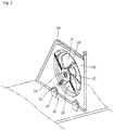
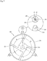
- FIG. 2 is a rear perspective view of a surface of an apparatus, which shows the fan 110 coupled to the shroud 120
- FIG. 3 is another perspective of the apparatus showing a coupling unit coupling the shroud 120 to the surface 10 in the apparatus according to a non-limiting embodiment of the present invention
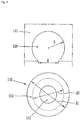
- FIG. 4 is a front view of a receiving portion and a vibration preventing member of the coupling assembly of FIG. 3 .
- the fan 110 having a motor 130 coupled thereto is mounted to the shroud 120 for support, and the shroud 120 is coupled to a bottom surface of the apparatus by coupling units 140.
- Vibration preventing members 150 are disposed at the coupling units 140.
- the motor 130 may be configured as an outer rotor type motor.
- a stator is disposed inside a rotor, and the rotor is disposed within the fan 110.
- the motor 130 is mounted to and supported by the shroud 120.
- the shroud 120 includes an opening 123 through which air generated by the fan 110 passes.
- the motor 130 is mounted to a motor mounting portion 121 disposed at a central part of the opening 123, and the motor mounting portion 121 is supported by four motor supporting portions 122 extending therefrom; however, the present invention contemplates providing fewer or more motor supporting portions to support the motor mounting portion and the motor mounted thereto.
- the opening 123 is configured with a diameter so as to be adjacent with an outer radial edge of the fan 110.
- the diameter of the opening 123 is larger than a diameter of the radial edge of the fan 110 such that the fan 110 may be disposed within the diameter of the opening 123.
- An end portion of the opening 123 may be provided such that a concave surface of the end portion extends radially along the opening 123 in a downstream direction of the fan 110.
- air flowing in a downstream direction of the fan 110 is prevented from leaking in a radial direction of the fan 110, thereby preventing noise caused by air leakage.
- the coupling units 140 include receiving portions 141 disposed at lower sides of the shroud 120, and shroud coupling portions 142 that protrude from a bottom surface of the machine room 10 in correspondence to the receiving portions 141.
- the receiving portions 141 are provided at lower ends of the shroud 120, and are downwardly opened and may be configured as arcuate slots, or any other suitable shape to couple with a complimentary structure.
- two receiving portions 141 are provided; however fewer or more receiving portions may be provided for additional stability of the shroud and related components.
- the shroud coupling portions 142 protrude from the bottom surface of the apparatus in correspondence to the receiving portions 141.
- the shroud coupling portions 142 may be rectangular in shape (although other suitable shapes are contemplated by the present invention).
- Coupling holes (not labeled) may be provided at a central part of the shroud coupling portions 142. The coupling holes are linearly aligned along a central axis in the axial direction of the receiving portion 141, the shroud coupling portion 142, and the coupling member 143.
- Vibration preventing members 150 are disposed between the coupiing units 140.
- the vibration preventing members 150 are further disposed within the receiving portions 141, and are coupled to the shroud coupling portions 142 in a side direction by coupling members 143.
- the vibration preventing members 150 are disposed between the receiving portions 141 and the shroud coupling portions 142, such that direct contact between the receiving portions 141 and the shroud coupling portions 142 is prevented. Accordingly, vibration and noise generated from the fan 110 and the shroud 120 are prevented from being transmitted to the apparatus via the shroud coupling portions 142, and absorbed by the vibration preventing members 150.
- the coupling members 143 may be configured as bolts or pins that can be easily detachably mounted, or any other suitable removable fastener.
- the vibration preventing members 150 are cylindrical in shape, although other suitable shapes are contemplated by the present invention, and an aperture 152 extends through a central part therethrough creating an inner diameter (d2) and an outer diameter (d1).
- the vibration preventing members 150 may be made of rubber or any suitable material known to absorb and dampen vibrations and/or noise.
- Fitting grooves 151 are provided along a central part of the outer diameter (d1) in a circumferential direction such that the fitting grooves 151 mate with receiving portions 141 at an inner arcuate surface of the arcuate slot. The fitting grooves 151 mated with the receiving portions 141 prevent the vibration preventing members 150 from moving in a thickness direction.
- each of the receiving portions 141 is provided such that an inlet width (W) thereof may be narrower than each outer diameter (d1) of the vibration preventing members 150.
- the inlet width is configured to receive the vibration preventing member 150 via the fitting groove 151.
- a curvature radius (R) of the inner arcuate surface of each of the receiving portions 141 is configured to be smaller than 1/2 of each outer diameter (d1) of the vibration preventing members 150, and is configured to be equal to or smaller than 1/2 of the diameter (d2) of the fitting groove 151.
- the vibration preventing members 150 are prevented from rotating along the inner arcuate surface of the receiving portions 141.
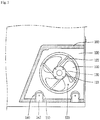
- FIG. 5 is a longitudinal section view of the shroud and the coupling assembly in the apparatus according to the first non-limiting embodiment of the present invention.
- the shroud 120 is provided so as to correspond to the shape of a longitudinal section of the apparatus. More specifically, the shroud 120 is configured so as to fit within the longitudinal section of the apparatus.
- a hermetic member 160 is further provided on an outer perimeter of the shroud 120 and contacts inner surfaces of the apparatus.
- the hermetic member 160 may be configured as an elastic member such as a sponge or a rubber liner, although other sealing mechanisms are contemplated by the present invention.
- the hermetic member 160 prevents air from passing through gaps between the outer perimeter of the shroud 120 and the inner surfaces of the machine room 10. Accordingly, air flows only through the opening 123, and thus the condenser 30 can dissipate heat more efficiently.
- vibration generated by the operation of the motor 130 and rotation of the fan 110 at the shroud 120 is prevented from being transmitted to the machine room 10.
- the shroud 120 is coupled to the shroud coupling portion 142 such that the shroud 120 is spaced from the bottom surface of the machine room 10 by the hermetic member 160.
- a portion of the hermetic member 160 extending along the outer perimeter of the shroud 120 is provided in the space between the shroud 120 and the bottom surface of the apparatus to prevent air from passing therethrough.
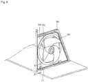
- FIGS. 6 and 7 provide a fan that may be installed in an apparatus according to the example.
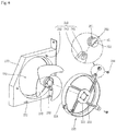
- FIG. 6 is an exploded view of a frame 270, a shroud 220, and a fan 210
- FIG. 7 is a rear view of the shroud of FIG. 6 .
- the fan 210 coupled to a motor 230 may be provided in the apparatus so as to dissipate heat from the compressor 40 and the condenser 30.
- the motor 230 is mounted to a motor mounting portion 221 of the shroud 220, and the motor mounting portion 221 is connected to the shroud 220 by a plurality of motor supporting portions 222.
- the motor 230 is mounted to and supported by the shroud 220.
- the shroud 220 includes a shroud ring 224 and is disposed such that the shroud ring 224 is adjacent to an outer circumferential surface of the fan 210.
- the shroud ring 224 is provided in a ring shape having a certain width in a radial direction of the fan 210 such that the flow of air generated by the fan 210 is guided therethrough.
- the shroud ring 224 protrudes in an upstream direction of the fan 210, and is configured with a concave surface in a downstream direction of the fan 210.
- the shroud 220 is coupled to the frame 270 and the frame 270 is fixed to the apparatus surface via frame coupling portions 271.
- the shroud 220 and the frame 270 are provided with coupling units 240 for coupling therebetween, respectively.
- Vibration preventing members 250 configured to prevent vibration and noise (generated by the operation of the motor 230 and the rotation of the fan 210) from being transmitted to the apparatus through the frame 270 are interposed between the coupling units 240.
- the frame 270 is provided with an opening 223 corresponding to a diameter of the shroud ring 224.
- the shroud ring 224 is accommodated in the opening 223.
- an end portion of the opening 223 protrude in the upstream direction of the fan 210, and has the concave surface in the downstream direction of the fan 210.
- the coupling units 240 include protrusions 243 outwardly protruding from an outer circumference of the shroud ring 224 in a radial direction, receiving portions 241 having an arcuate surface are provided at the end of the protrusions 243 so as to be opened in the protruding direction, and shroud coupling portions 242 provided at the frame 270 in correspondence to the receiving portions 241.
- two protrusions 243 are provided; however, fewer or more protrusions are contemplated by the present invention.
- the protrusions 243 are provided at an outer edge of the shroud ring 224 extending in the radial direction with a constant angle therebetween.
- the protrusions 243 are provided so that angles therebetween of ⁇ , ⁇ , and ⁇ can be equal to each other to uniformly distribute vibration generated by operation of the motor 230 and rotation of the fan 210.
- Vibration preventing members 250 are received by the receiving portions 241 along the radial direction of the shroud ring 224, and are coupled to the frame 270 in a side direction via the shroud coupling portion 242.
- the receiving portions 241 are provided such that each inlet width (W) thereof can be narrower than each outer diameter (d1) of the vibration preventing members 250 (having the same configuration as the vibration preventing members described in the first non-limiting embodiment).
- Fitting grooves 251 fitted into the receiving portions 241 extend along the outer circumferential surfaces of the vibration preventing members 250.
- the fitting grooves 251 prevent the vibration preventing members 250 fitted into the receiving portions 241 from moving in a thickness direction (i.e., an axial direction).
- Coupling holes 252 are provided through a central part of the vibration preventing members 250 in the thickness direction.
- Coupling members 244 for coupling the shroud 220 and the frame 270 to each other are provided to penetrate the coupling holes 252.
- the coupling members 244 are coupled to the shroud coupling portions 242 provided on the rear surface of the frame 270 in correspondence to the protrusions 243.
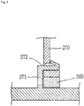
- FIG 8 is a view of a fan assembly according to another example, showing that the frame is coupled to the apparatus
- FIG. 9 is a sectional view taken along line 'II-II' in FIG. 8 .
- the frame 270 is provided so as to correspond to a shape of a longitudinal section of the apparatus.
- a hermetic member 260 is further provided on an outer perimeter of the frame 270 and contacts inner surfaces of the apparatus.
- the hermetic member may be made of a sponge or rubber liner, or any other suitable sealing material.
- the hermetic member 260 prevents air from passing through gaps between the outer perimeter of the frame 270 and inner surfaces of the apparatus. Accordingly, air flows only through the shroud ring 224 accommodated in the opening 223, and thus the condenser 30 can dissipate heat more efficiently.
- vibration of the frame 270 that would otherwise be transmitted to the inner surfaces of the apparatus due to vibration of the motor 230 and fan 210 is prevented.
- the frame 270 is fixedly coupled to frame coupling portions 271 provided on a bottom surface of the apparatus.
- the frame coupling portions 271 protrude from a bottom surface of the apparatus. Insertion portions 272 configured to mate with the frame coupling portions 271 are provided at a lower side of the frame 270 parallel to the bottom surface of the apparatus.
- the frame coupling portions 271 further include a locking protrusion (that is also provided parallel to the bottom surface of the apparatus) that engages the insertion portions 272.
- the locking protrusion includes an elastically deformable locking arm that extends at an acute angle from an upper surface of the locking protrusion such that it may be inserted through the insertion portions 272. That is, when the frame coupling portions 271 are inserted through the insertion portions 272, the locking arm abuts a surface at the lower side of the frame 270 such that the frame coupling portion 271 cannot be easily disengaged from the frame 270.
- the frame 270 may be integrally provided on a bottom surface of the apparatus.
- the former case is more preferable than the latter case in the aspect of assembly efficiency of the shroud 220 to the frame 270.
- the number of the frame coupling portions 271 may be varied so that the frame 270 can be stably fixed to a bottom surface of the apparatus.
- the fan assembly according to the first non-limiting embodiment of the present invention has the following advantages.
- the vibration preventing members are interposed between the coupling units of the shroud and the machine room. Therefore, the amount of vibration and noise transmitted from the fan and the motor to the apparatus can be reduced. That is, the vibration preventing members dampen (e.g., absorb) the vibration and reduce noise generation.
- the hermetic member is provided on the outer perimeter surface of the shroud, air generated by the fan flows only through the opening of the shroud. Accordingly, effectiveness of heat dissipation from the condenser and the compressor is enhanced, and the amount of vibration and noise transmitted to the apparatus through the outer perimeter of the shroud can be reduced.
- the fan assembly according to another example has the following advantage.
- the vibration preventing members are interposed between the shroud and the frame to reduce the amount of vibration and noise transmitted to the machine room from the fan and the motor.
- inventions of the disclosure may be referred to herein, individually and/or collectively, by the term "invention" merely for convenience and without intending to voluntarily limit the scope of this application to any particular invention or inventive concept.
- inventions may be referred to herein, individually and/or collectively, by the term "invention" merely for convenience and without intending to voluntarily limit the scope of this application to any particular invention or inventive concept.
- specific embodiments have been illustrated and described herein, it should be appreciated that any subsequent arrangement designed to achieve the same or similar purpose may be substituted for the specific embodiments shown.
- This disclosure is intended to cover any and all subsequent adaptations or variations of various embodiments. Combinations of the above embodiments, and other embodiments not specifically described herein, will be apparent to those of skill in the art upon reviewing the description.
Landscapes
- Engineering & Computer Science (AREA)
- Mechanical Engineering (AREA)
- General Engineering & Computer Science (AREA)
- Chemical & Material Sciences (AREA)
- Combustion & Propulsion (AREA)
- Physics & Mathematics (AREA)
- Thermal Sciences (AREA)
- Structures Of Non-Positive Displacement Pumps (AREA)
- Cold Air Circulating Systems And Constructional Details In Refrigerators (AREA)
- Motor Or Generator Frames (AREA)
Claims (4)
- Lüfteranordnung, die aufweist:einen Lüfter (110);eine Verkleidung (120), die einen Motormontageabschnitt aufweist, auf dem ein Lüftermotor des Lüfters montiert ist;eine oder mehrere Kopplungseinheiten (140), die auf einer Unterseite der Verkleidung bereitgestellt sind, welche die Verkleidung mit einer planaren Oberfläche eines Maschinenraums eines Kühlschranks, der mit einem Verdichter und einem Kondensator darin versehen ist, koppeln; undein oder mehrere Schwingungsvermeidungselemente (150), die zwischen den Kopplungseinheiten und der Verkleidung eingefügt sind,dadurch gekennzeichnet, dass jede der einen oder mehreren Kopplungseinheiten einen Aufnahmeabschnitt (141), der als eine Öffnung an einem unteren Ende der Verkleidung ausgebildet ist, und einen Verkleidungskopplungsabschnitt (142), der von der planaren Oberfläche des Maschinenraums nach oben vorsteht, um mit dem Aufnahmeabschnitt ausgerichtet zu sein, aufweist,wobei der Aufnahmeabschnitt (141) einen nach unten geöffneten Schlitz, der in einem unteren Ende der Verkleidung ausgebildet ist, aufweist, wobei der Aufnahmeabschnitt eines des einen oder der mehreren Schwingungsvermeidungselemente (150) darin aufnimmt, wobei das eine des einen oder der mehreren Schwingungsvermeidungselemente zwischen dem Aufnahmeabschnitt (141) und dem Verkleidungskopplungsabschnitt (142) positioniert ist,wobei jedes des einen oder der mehreren Schwingungsvermeidungselemente (150) eine Passnut (151) aufweist, die in seiner Außenseitenoberfläche ausgebildet ist, die in eine entsprechende Innenseitenoberfläche ihres jeweiligen Aufnahmeabschnitts (141) eingreift, undwobei Kopplungslöcher (152), die an den Schwingungsvermeidungselementen (150) und den Verkleidungskopplungsabschnitten (142) bereitgestellt sind, Kopplungselemente (143) aufnehmen, die konfiguriert sind, um die Schwingungsvermeidungselemente (150) und die Verkleidungskopplungsabschnitte (142) in einer Seitenrichtung zu koppeln.
- Lüfteranordnung nach Anspruch 1, wobei die Aufnahmeabschnitte derart konfiguriert sind, dass jede ihrer Einlassbreiten schmale als jeder Außendurchmesser der Schwingungsvermeidungselemente ist.
- Lüfteranordnung nach einem der Ansprüche 1 bis 2, wobei die Verkleidung konfiguriert ist, um zu einer Form eines Längsschnitts des Maschinenraums zu passen, und ferner ein hermetisches Element auf einem Außenrand der Verkleidung bereitgestellt ist, das eine Innenoberfläche des Maschinenraums berührt.
- Lüfteranordnung nach einem der Ansprüche 1 bis 3, wobei ein unteres Ende der Verkleidung mit der planaren Oberfläche des Maschinenraums gekoppelt ist, wobei ein Abstand zwischen ihnen bereitgestellt ist.
Applications Claiming Priority (1)
| Application Number | Priority Date | Filing Date | Title |
|---|---|---|---|
| KR1020070140932A KR101427269B1 (ko) | 2007-12-28 | 2007-12-28 | 냉장고 |
Publications (3)
| Publication Number | Publication Date |
|---|---|
| EP2075472A2 EP2075472A2 (de) | 2009-07-01 |
| EP2075472A3 EP2075472A3 (de) | 2017-02-22 |
| EP2075472B1 true EP2075472B1 (de) | 2020-06-17 |
Family
ID=40445889
Family Applications (1)
| Application Number | Title | Priority Date | Filing Date |
|---|---|---|---|
| EP08170943.8A Active EP2075472B1 (de) | 2007-12-28 | 2008-12-08 | Lüfterbaugruppe |
Country Status (4)
| Country | Link |
|---|---|
| US (1) | US8337155B2 (de) |
| EP (1) | EP2075472B1 (de) |
| KR (1) | KR101427269B1 (de) |
| CN (1) | CN101469723B (de) |
Families Citing this family (35)
| Publication number | Priority date | Publication date | Assignee | Title |
|---|---|---|---|---|
| KR20110019074A (ko) * | 2009-08-19 | 2011-02-25 | 엘지전자 주식회사 | 냉장고 |
| KR101660720B1 (ko) * | 2009-08-24 | 2016-09-28 | 엘지전자 주식회사 | 냉장고 |
| TWI395876B (zh) * | 2009-10-20 | 2013-05-11 | Yen Sun Technology Corp | Can absorb the vibration of the fan |
| TWI395877B (zh) * | 2009-11-11 | 2013-05-11 | Yen Sun Technology Corp | Shock absorber |
| KR101897728B1 (ko) * | 2011-09-15 | 2018-09-12 | 엘지전자 주식회사 | 나셀 형상을 이용한 냉장고 기계실 냉각 장치 |
| TWI504808B (zh) * | 2012-05-15 | 2015-10-21 | Delta Electronics Inc | 振動風扇 |
| DE102012218347A1 (de) * | 2012-10-09 | 2014-05-15 | BSH Bosch und Siemens Hausgeräte GmbH | Lüftereinheit |
| CN103335196A (zh) * | 2013-07-09 | 2013-10-02 | 樊书印 | 一种微型风扇 |
| CN104344639B (zh) * | 2013-10-18 | 2017-02-08 | 海尔集团公司 | 一种风机固定结构 |
| KR102168586B1 (ko) * | 2013-11-29 | 2020-10-22 | 삼성전자주식회사 | 냉장고 |
| TWI525966B (zh) | 2013-11-29 | 2016-03-11 | Sunonwealth Electruc Machine Industry Co Ltd | Motor and its motor shock mechanism |
| US20150233388A1 (en) * | 2014-02-18 | 2015-08-20 | Ciena Corporation | Telecommunications system cooling fan incorporating a compact vibration isolator |
| EP2993427B1 (de) * | 2014-09-05 | 2018-03-21 | Samsung Electronics Co., Ltd. | Kühlschrank |
| US20160116204A1 (en) * | 2014-10-22 | 2016-04-28 | General Electric Company | Fan with integrated plenum |
| CN104564848A (zh) * | 2014-12-30 | 2015-04-29 | 合肥晶弘电器有限公司 | 一种风扇降噪结构及冰箱 |
| CN107023499B (zh) * | 2016-01-29 | 2020-04-24 | 台达电子工业股份有限公司 | 风扇及散热装置 |
| KR101798574B1 (ko) * | 2016-05-02 | 2017-11-17 | 동부대우전자 주식회사 | 방열용 송풍기 및 이를 포함하는 냉장고 |
| TR201607826A2 (tr) * | 2016-06-09 | 2017-12-21 | Arcelik As | Bi̇r fan terti̇batina sahi̇p buzdolabi |
| KR101878072B1 (ko) * | 2016-10-26 | 2018-07-12 | 엘지전자 주식회사 | 냉장고의 압축기 설치 구조 및 그 설치 방법 |
| KR20180109311A (ko) * | 2017-03-27 | 2018-10-08 | 주식회사 대우전자 | 냉장고 및 냉장고용 팬 어셈블리 |
| DE102017206505A1 (de) * | 2017-04-18 | 2018-10-18 | BSH Hausgeräte GmbH | Kältegerät mit einer Dämpfungsscheibe |
| KR101976291B1 (ko) * | 2017-12-13 | 2019-05-07 | 엘지전자 주식회사 | 컴팩트 기계실을 위한 제상수 받이 및 이를 적용한 냉장고 |
| KR102004047B1 (ko) | 2017-10-23 | 2019-07-25 | 엘지전자 주식회사 | 컴팩트 기계실을 위한 제상수 받이 및 이를 적용한 냉장고 |
| CN207963280U (zh) * | 2017-11-27 | 2018-10-12 | 博西华电器(江苏)有限公司 | 冰箱 |
| TWI663815B (zh) * | 2018-01-12 | 2019-06-21 | 元山科技工業股份有限公司 | 減震風扇 |
| CN108180174B (zh) * | 2018-01-23 | 2019-01-08 | 温州捷高科技有限公司 | 一种电动汽车风扇风罩 |
| JP6988615B2 (ja) * | 2018-03-20 | 2022-01-05 | 株式会社デンソー | 電動ポンプの取付け構造 |
| US10801771B2 (en) * | 2018-05-14 | 2020-10-13 | Heatcraft Refrigeration Products Llc | Condenser fan motor mounts and guards |
| US11268538B2 (en) * | 2019-04-03 | 2022-03-08 | Dell Products L.P. | Multiple function fan holder |
| US11624543B2 (en) * | 2019-08-26 | 2023-04-11 | Lg Electronics Inc. | Under counter type refrigerator |
| CN114183955B (zh) * | 2020-09-14 | 2024-07-12 | 青岛海尔电冰箱有限公司 | 储物装置 |
| CN113357178A (zh) * | 2021-07-13 | 2021-09-07 | 阳光电源股份有限公司 | 一种风扇组件及逆变器 |
| TWI822397B (zh) * | 2022-10-18 | 2023-11-11 | 元山科技工業股份有限公司 | 軸流散熱風扇之減振框架 |
| DE102022212849B4 (de) | 2022-11-30 | 2025-07-17 | BSH Hausgeräte GmbH | Kältegerät |
| CN119142516A (zh) * | 2024-11-20 | 2024-12-17 | 浙江长空动力科技有限公司 | 一种涵道风扇结构 |
Citations (1)
| Publication number | Priority date | Publication date | Assignee | Title |
|---|---|---|---|---|
| JP2000027799A (ja) * | 1998-07-10 | 2000-01-25 | Toshiba Corp | ファン装置 |
Family Cites Families (28)
| Publication number | Priority date | Publication date | Assignee | Title |
|---|---|---|---|---|
| US2451970A (en) * | 1945-03-03 | 1948-10-19 | Vornado Trust | Mounting for fan assemblies |
| DE1428037A1 (de) * | 1964-05-16 | 1968-11-28 | Bahco Ab | Ventilator mit vibrationsdaempfender Aufhaengung |
| US3714795A (en) * | 1970-03-31 | 1973-02-06 | Tappan Co | Outdoor refrigerant apparatus |
| US3773285A (en) * | 1972-02-18 | 1973-11-20 | W Morrill | Flexible machine mounting |
| US4036292A (en) * | 1975-10-21 | 1977-07-19 | Westinghouse Electric Corporation | Refrigeration condenser |
| GB2234012A (en) | 1989-07-14 | 1991-01-23 | Ibm | Dc motor driven centrifugal fan |
| DE8908987U1 (de) * | 1989-07-25 | 1989-11-02 | Neuhaus, Gerhard, Dipl.-Ing., 6301 Fernwald | Ventilatoraggregat |
| DE4238895C1 (de) * | 1992-11-19 | 1993-12-16 | Howatherm Klimatech Gmbh | Ventilatoraggregat zum Einbau in einen Luftkanal eines raumlufttechnischen Gerätes |
| KR0128829Y1 (ko) * | 1993-05-29 | 1999-01-15 | 구자홍 | 에어콘 실외기의 송풍팬 지지구조 |
| JP3487382B2 (ja) * | 1994-12-28 | 2004-01-19 | 株式会社デンソー | 沸騰冷却装置 |
| US20020088237A1 (en) * | 1999-10-05 | 2002-07-11 | Rudick Arthur G. | Apparatus using vibrationally isolating stirling cooler system |
| CN2472459Y (zh) | 2001-01-16 | 2002-01-16 | 联想(北京)有限公司 | 无螺钉的机箱风扇固定装置 |
| CN1239872C (zh) * | 2001-05-09 | 2006-02-01 | 株式会社日立制作所 | 冰箱 |
| KR100827779B1 (ko) * | 2002-08-08 | 2008-05-07 | 엘지전자 주식회사 | 냉장고의 팬모터 지지구조 |
| KR100471444B1 (ko) * | 2002-08-14 | 2005-03-08 | 엘지전자 주식회사 | 송풍팬 |
| KR100484828B1 (ko) * | 2002-11-27 | 2005-04-22 | 엘지전자 주식회사 | 냉장고의 냉기순환용 축류팬 |
| KR100547328B1 (ko) * | 2003-09-05 | 2006-01-26 | 엘지전자 주식회사 | 에어컨 실외기의 축류팬 |
| KR100569891B1 (ko) * | 2003-12-18 | 2006-04-10 | 엘지전자 주식회사 | 냉장고의 송풍팬 운전 제어방법 |
| US6980435B2 (en) * | 2004-01-28 | 2005-12-27 | Hewlett-Packard Development Company, L.P. | Modular electronic enclosure with cooling design |
| JP2005214617A (ja) * | 2004-01-28 | 2005-08-11 | Lg Electronics Inc | 横流ファンを有する冷蔵庫 |
| TWI322230B (en) * | 2005-06-30 | 2010-03-21 | Delta Electronics Inc | Fan module and its fan casing |
| US7342789B2 (en) * | 2005-06-30 | 2008-03-11 | International Business Machines Corporation | Method and apparatus for cooling an equipment enclosure through closed-loop, liquid-assisted air cooling in combination with direct liquid cooling |
| KR100737982B1 (ko) * | 2005-07-12 | 2007-07-13 | 삼성광주전자 주식회사 | 밀폐형 압축기 |
| JP4618077B2 (ja) | 2005-09-27 | 2011-01-26 | 株式会社デンソー | 冷却ファンおよび送風機 |
| CN101022196A (zh) | 2006-02-15 | 2007-08-22 | 鸿富锦精密工业(深圳)有限公司 | 风扇电源转接装置 |
| US7488152B2 (en) * | 2006-04-10 | 2009-02-10 | Super Micro Computer, Inc. | Vibration absorption device for a fan |
| KR100713122B1 (ko) | 2006-06-13 | 2007-05-02 | 위니아만도 주식회사 | 응축기용 팬모터의 결합구조 |
| TWM313415U (en) * | 2006-12-07 | 2007-06-01 | Inventec Corp | Fixing mechanism for fan frame use |
-
2007
- 2007-12-28 KR KR1020070140932A patent/KR101427269B1/ko not_active Expired - Fee Related
-
2008
- 2008-12-03 US US12/327,039 patent/US8337155B2/en not_active Expired - Fee Related
- 2008-12-08 EP EP08170943.8A patent/EP2075472B1/de active Active
- 2008-12-26 CN CN2008101906395A patent/CN101469723B/zh not_active Expired - Fee Related
Patent Citations (1)
| Publication number | Priority date | Publication date | Assignee | Title |
|---|---|---|---|---|
| JP2000027799A (ja) * | 1998-07-10 | 2000-01-25 | Toshiba Corp | ファン装置 |
Also Published As
| Publication number | Publication date |
|---|---|
| EP2075472A2 (de) | 2009-07-01 |
| US8337155B2 (en) | 2012-12-25 |
| KR20090072734A (ko) | 2009-07-02 |
| EP2075472A3 (de) | 2017-02-22 |
| CN101469723A (zh) | 2009-07-01 |
| CN101469723B (zh) | 2012-11-07 |
| US20090169387A1 (en) | 2009-07-02 |
| KR101427269B1 (ko) | 2014-08-06 |
Similar Documents
| Publication | Publication Date | Title |
|---|---|---|
| EP2075472B1 (de) | Lüfterbaugruppe | |
| US11060784B2 (en) | Fan assembly and refrigerator including a fan assembly | |
| US20120167608A1 (en) | Outdoor unit for air conditioner | |
| RU2629974C2 (ru) | Вентиляторный блок | |
| CN110520632B (zh) | 具有减振盘的制冷器具 | |
| KR101463812B1 (ko) | 냉장고의 팬모듈 | |
| RU2579361C1 (ru) | Холодильный аппарат с вентилятором | |
| EP3604817B1 (de) | Verdichteranordnung für haushaltskühlmaschine | |
| CN212108714U (zh) | 立式空调器及其室内机 | |
| CN107339843B (zh) | 散热风机和包括散热风机的冰箱 | |
| US20170314568A1 (en) | In-refrigerator blower and refrigerator including the same | |
| CN104813037A (zh) | 通风器组件 | |
| KR200211736Y1 (ko) | 공기조화기용 진동흡수장치 | |
| CN224033915U (zh) | 空调 | |
| US10837461B2 (en) | Vibration isolating mounting of fan | |
| KR200232359Y1 (ko) | 패키지에어콘의송풍기고정장치 | |
| CN113970134B (zh) | 空调器 | |
| KR20150125358A (ko) | 냉장고용 팬 어셈블리 | |
| JP2025108933A (ja) | 圧縮機 | |
| CN120576418A (zh) | 风管机 | |
| KR20250049489A (ko) | 압축기 커버 | |
| KR20180033974A (ko) | 실외기 및 그것을 구비하는 공기조화기 | |
| CN104220827A (zh) | 具有通风器单元的制冷器具 | |
| JP2015045230A (ja) | 気体圧縮機 | |
| KR20000067362A (ko) | 냉동 시스템용 모터의 역회전 방지장치 |
Legal Events
| Date | Code | Title | Description |
|---|---|---|---|
| PUAI | Public reference made under article 153(3) epc to a published international application that has entered the european phase |
Free format text: ORIGINAL CODE: 0009012 |
|
| 17P | Request for examination filed |
Effective date: 20090107 |
|
| AK | Designated contracting states |
Kind code of ref document: A2 Designated state(s): AT BE BG CH CY CZ DE DK EE ES FI FR GB GR HR HU IE IS IT LI LT LU LV MC MT NL NO PL PT RO SE SI SK TR |
|
| AX | Request for extension of the european patent |
Extension state: AL BA MK RS |
|
| RIC1 | Information provided on ipc code assigned before grant |
Ipc: F04D 29/42 20060101AFI20160829BHEP Ipc: F04D 29/64 20060101ALI20160829BHEP Ipc: F04D 29/66 20060101ALI20160829BHEP Ipc: F04D 29/52 20060101ALI20160829BHEP |
|
| PUAL | Search report despatched |
Free format text: ORIGINAL CODE: 0009013 |
|
| AK | Designated contracting states |
Kind code of ref document: A3 Designated state(s): AT BE BG CH CY CZ DE DK EE ES FI FR GB GR HR HU IE IS IT LI LT LU LV MC MT NL NO PL PT RO SE SI SK TR |
|
| AX | Request for extension of the european patent |
Extension state: AL BA MK RS |
|
| RIC1 | Information provided on ipc code assigned before grant |
Ipc: F04D 29/52 20060101ALI20170118BHEP Ipc: F04D 29/64 20060101ALI20170118BHEP Ipc: F04D 29/42 20060101AFI20170118BHEP Ipc: F04D 29/66 20060101ALI20170118BHEP |
|
| RBV | Designated contracting states (corrected) |
Designated state(s): AT BE BG CH CY CZ DE DK EE ES FI FR GB GR HR HU IE IS IT LI LT LU LV MC MT NL NO PL PT RO SE SI SK TR |
|
| AKX | Designation fees paid |
Designated state(s): AT BE BG CH CY CZ DE DK EE ES FI FR GB GR HR HU IE IS IT LI LT LU LV MC MT NL NO PL PT RO SE SI SK TR |
|
| AXX | Extension fees paid |
Extension state: AL Extension state: MK Extension state: RS Extension state: BA |
|
| STAA | Information on the status of an ep patent application or granted ep patent |
Free format text: STATUS: EXAMINATION IS IN PROGRESS |
|
| 17Q | First examination report despatched |
Effective date: 20180306 |
|
| GRAP | Despatch of communication of intention to grant a patent |
Free format text: ORIGINAL CODE: EPIDOSNIGR1 |
|
| STAA | Information on the status of an ep patent application or granted ep patent |
Free format text: STATUS: GRANT OF PATENT IS INTENDED |
|
| INTG | Intention to grant announced |
Effective date: 20200306 |
|
| GRAS | Grant fee paid |
Free format text: ORIGINAL CODE: EPIDOSNIGR3 |
|
| GRAA | (expected) grant |
Free format text: ORIGINAL CODE: 0009210 |
|
| STAA | Information on the status of an ep patent application or granted ep patent |
Free format text: STATUS: THE PATENT HAS BEEN GRANTED |
|
| AK | Designated contracting states |
Kind code of ref document: B1 Designated state(s): AT BE BG CH CY CZ DE DK EE ES FI FR GB GR HR HU IE IS IT LI LT LU LV MC MT NL NO PL PT RO SE SI SK TR |
|
| REG | Reference to a national code |
Ref country code: GB Ref legal event code: FG4D |
|
| REG | Reference to a national code |
Ref country code: CH Ref legal event code: EP |
|
| REG | Reference to a national code |
Ref country code: IE Ref legal event code: FG4D |
|
| REG | Reference to a national code |
Ref country code: DE Ref legal event code: R096 Ref document number: 602008062852 Country of ref document: DE |
|
| REG | Reference to a national code |
Ref country code: AT Ref legal event code: REF Ref document number: 1281639 Country of ref document: AT Kind code of ref document: T Effective date: 20200715 |
|
| PG25 | Lapsed in a contracting state [announced via postgrant information from national office to epo] |
Ref country code: GR Free format text: LAPSE BECAUSE OF FAILURE TO SUBMIT A TRANSLATION OF THE DESCRIPTION OR TO PAY THE FEE WITHIN THE PRESCRIBED TIME-LIMIT Effective date: 20200918 Ref country code: NO Free format text: LAPSE BECAUSE OF FAILURE TO SUBMIT A TRANSLATION OF THE DESCRIPTION OR TO PAY THE FEE WITHIN THE PRESCRIBED TIME-LIMIT Effective date: 20200917 Ref country code: LT Free format text: LAPSE BECAUSE OF FAILURE TO SUBMIT A TRANSLATION OF THE DESCRIPTION OR TO PAY THE FEE WITHIN THE PRESCRIBED TIME-LIMIT Effective date: 20200617 Ref country code: SE Free format text: LAPSE BECAUSE OF FAILURE TO SUBMIT A TRANSLATION OF THE DESCRIPTION OR TO PAY THE FEE WITHIN THE PRESCRIBED TIME-LIMIT Effective date: 20200617 Ref country code: FI Free format text: LAPSE BECAUSE OF FAILURE TO SUBMIT A TRANSLATION OF THE DESCRIPTION OR TO PAY THE FEE WITHIN THE PRESCRIBED TIME-LIMIT Effective date: 20200617 |
|
| REG | Reference to a national code |
Ref country code: LT Ref legal event code: MG4D |
|
| REG | Reference to a national code |
Ref country code: NL Ref legal event code: MP Effective date: 20200617 |
|
| PG25 | Lapsed in a contracting state [announced via postgrant information from national office to epo] |
Ref country code: HR Free format text: LAPSE BECAUSE OF FAILURE TO SUBMIT A TRANSLATION OF THE DESCRIPTION OR TO PAY THE FEE WITHIN THE PRESCRIBED TIME-LIMIT Effective date: 20200617 Ref country code: LV Free format text: LAPSE BECAUSE OF FAILURE TO SUBMIT A TRANSLATION OF THE DESCRIPTION OR TO PAY THE FEE WITHIN THE PRESCRIBED TIME-LIMIT Effective date: 20200617 Ref country code: BG Free format text: LAPSE BECAUSE OF FAILURE TO SUBMIT A TRANSLATION OF THE DESCRIPTION OR TO PAY THE FEE WITHIN THE PRESCRIBED TIME-LIMIT Effective date: 20200917 |
|
| REG | Reference to a national code |
Ref country code: AT Ref legal event code: MK05 Ref document number: 1281639 Country of ref document: AT Kind code of ref document: T Effective date: 20200617 |
|
| PG25 | Lapsed in a contracting state [announced via postgrant information from national office to epo] |
Ref country code: NL Free format text: LAPSE BECAUSE OF FAILURE TO SUBMIT A TRANSLATION OF THE DESCRIPTION OR TO PAY THE FEE WITHIN THE PRESCRIBED TIME-LIMIT Effective date: 20200617 |
|
| PG25 | Lapsed in a contracting state [announced via postgrant information from national office to epo] |
Ref country code: PT Free format text: LAPSE BECAUSE OF FAILURE TO SUBMIT A TRANSLATION OF THE DESCRIPTION OR TO PAY THE FEE WITHIN THE PRESCRIBED TIME-LIMIT Effective date: 20201019 Ref country code: IT Free format text: LAPSE BECAUSE OF FAILURE TO SUBMIT A TRANSLATION OF THE DESCRIPTION OR TO PAY THE FEE WITHIN THE PRESCRIBED TIME-LIMIT Effective date: 20200617 Ref country code: CZ Free format text: LAPSE BECAUSE OF FAILURE TO SUBMIT A TRANSLATION OF THE DESCRIPTION OR TO PAY THE FEE WITHIN THE PRESCRIBED TIME-LIMIT Effective date: 20200617 Ref country code: RO Free format text: LAPSE BECAUSE OF FAILURE TO SUBMIT A TRANSLATION OF THE DESCRIPTION OR TO PAY THE FEE WITHIN THE PRESCRIBED TIME-LIMIT Effective date: 20200617 Ref country code: ES Free format text: LAPSE BECAUSE OF FAILURE TO SUBMIT A TRANSLATION OF THE DESCRIPTION OR TO PAY THE FEE WITHIN THE PRESCRIBED TIME-LIMIT Effective date: 20200617 Ref country code: EE Free format text: LAPSE BECAUSE OF FAILURE TO SUBMIT A TRANSLATION OF THE DESCRIPTION OR TO PAY THE FEE WITHIN THE PRESCRIBED TIME-LIMIT Effective date: 20200617 Ref country code: AT Free format text: LAPSE BECAUSE OF FAILURE TO SUBMIT A TRANSLATION OF THE DESCRIPTION OR TO PAY THE FEE WITHIN THE PRESCRIBED TIME-LIMIT Effective date: 20200617 |
|
| PG25 | Lapsed in a contracting state [announced via postgrant information from national office to epo] |
Ref country code: IS Free format text: LAPSE BECAUSE OF FAILURE TO SUBMIT A TRANSLATION OF THE DESCRIPTION OR TO PAY THE FEE WITHIN THE PRESCRIBED TIME-LIMIT Effective date: 20201017 Ref country code: SK Free format text: LAPSE BECAUSE OF FAILURE TO SUBMIT A TRANSLATION OF THE DESCRIPTION OR TO PAY THE FEE WITHIN THE PRESCRIBED TIME-LIMIT Effective date: 20200617 Ref country code: PL Free format text: LAPSE BECAUSE OF FAILURE TO SUBMIT A TRANSLATION OF THE DESCRIPTION OR TO PAY THE FEE WITHIN THE PRESCRIBED TIME-LIMIT Effective date: 20200617 |
|
| REG | Reference to a national code |
Ref country code: DE Ref legal event code: R097 Ref document number: 602008062852 Country of ref document: DE |
|
| PLBE | No opposition filed within time limit |
Free format text: ORIGINAL CODE: 0009261 |
|
| STAA | Information on the status of an ep patent application or granted ep patent |
Free format text: STATUS: NO OPPOSITION FILED WITHIN TIME LIMIT |
|
| PG25 | Lapsed in a contracting state [announced via postgrant information from national office to epo] |
Ref country code: DK Free format text: LAPSE BECAUSE OF FAILURE TO SUBMIT A TRANSLATION OF THE DESCRIPTION OR TO PAY THE FEE WITHIN THE PRESCRIBED TIME-LIMIT Effective date: 20200617 |
|
| 26N | No opposition filed |
Effective date: 20210318 |
|
| PG25 | Lapsed in a contracting state [announced via postgrant information from national office to epo] |
Ref country code: SI Free format text: LAPSE BECAUSE OF FAILURE TO SUBMIT A TRANSLATION OF THE DESCRIPTION OR TO PAY THE FEE WITHIN THE PRESCRIBED TIME-LIMIT Effective date: 20200617 |
|
| REG | Reference to a national code |
Ref country code: CH Ref legal event code: PL |
|
| PG25 | Lapsed in a contracting state [announced via postgrant information from national office to epo] |
Ref country code: MC Free format text: LAPSE BECAUSE OF FAILURE TO SUBMIT A TRANSLATION OF THE DESCRIPTION OR TO PAY THE FEE WITHIN THE PRESCRIBED TIME-LIMIT Effective date: 20200617 |
|
| REG | Reference to a national code |
Ref country code: BE Ref legal event code: MM Effective date: 20201231 |
|
| PG25 | Lapsed in a contracting state [announced via postgrant information from national office to epo] |
Ref country code: LU Free format text: LAPSE BECAUSE OF NON-PAYMENT OF DUE FEES Effective date: 20201208 Ref country code: IE Free format text: LAPSE BECAUSE OF NON-PAYMENT OF DUE FEES Effective date: 20201208 |
|
| PG25 | Lapsed in a contracting state [announced via postgrant information from national office to epo] |
Ref country code: LI Free format text: LAPSE BECAUSE OF NON-PAYMENT OF DUE FEES Effective date: 20201231 Ref country code: CH Free format text: LAPSE BECAUSE OF NON-PAYMENT OF DUE FEES Effective date: 20201231 |
|
| PGFP | Annual fee paid to national office [announced via postgrant information from national office to epo] |
Ref country code: FR Payment date: 20211110 Year of fee payment: 14 |
|
| PG25 | Lapsed in a contracting state [announced via postgrant information from national office to epo] |
Ref country code: TR Free format text: LAPSE BECAUSE OF FAILURE TO SUBMIT A TRANSLATION OF THE DESCRIPTION OR TO PAY THE FEE WITHIN THE PRESCRIBED TIME-LIMIT Effective date: 20200617 Ref country code: MT Free format text: LAPSE BECAUSE OF FAILURE TO SUBMIT A TRANSLATION OF THE DESCRIPTION OR TO PAY THE FEE WITHIN THE PRESCRIBED TIME-LIMIT Effective date: 20200617 Ref country code: CY Free format text: LAPSE BECAUSE OF FAILURE TO SUBMIT A TRANSLATION OF THE DESCRIPTION OR TO PAY THE FEE WITHIN THE PRESCRIBED TIME-LIMIT Effective date: 20200617 |
|
| PG25 | Lapsed in a contracting state [announced via postgrant information from national office to epo] |
Ref country code: BE Free format text: LAPSE BECAUSE OF NON-PAYMENT OF DUE FEES Effective date: 20201231 |
|
| PGFP | Annual fee paid to national office [announced via postgrant information from national office to epo] |
Ref country code: GB Payment date: 20221107 Year of fee payment: 15 Ref country code: DE Payment date: 20220615 Year of fee payment: 15 |
|
| PG25 | Lapsed in a contracting state [announced via postgrant information from national office to epo] |
Ref country code: FR Free format text: LAPSE BECAUSE OF NON-PAYMENT OF DUE FEES Effective date: 20221231 |
|
| REG | Reference to a national code |
Ref country code: DE Ref legal event code: R119 Ref document number: 602008062852 Country of ref document: DE |
|
| GBPC | Gb: european patent ceased through non-payment of renewal fee |
Effective date: 20231208 |
|
| PG25 | Lapsed in a contracting state [announced via postgrant information from national office to epo] |
Ref country code: DE Free format text: LAPSE BECAUSE OF NON-PAYMENT OF DUE FEES Effective date: 20240702 |
|
| PG25 | Lapsed in a contracting state [announced via postgrant information from national office to epo] |
Ref country code: GB Free format text: LAPSE BECAUSE OF NON-PAYMENT OF DUE FEES Effective date: 20231208 |
|
| PG25 | Lapsed in a contracting state [announced via postgrant information from national office to epo] |
Ref country code: GB Free format text: LAPSE BECAUSE OF NON-PAYMENT OF DUE FEES Effective date: 20231208 Ref country code: DE Free format text: LAPSE BECAUSE OF NON-PAYMENT OF DUE FEES Effective date: 20240702 |