EP2075376A2 - Vorrichtung und System zur nachhaltigen Stadtentwässerung - Google Patents
Vorrichtung und System zur nachhaltigen Stadtentwässerung Download PDFInfo
- Publication number
- EP2075376A2 EP2075376A2 EP20080172907 EP08172907A EP2075376A2 EP 2075376 A2 EP2075376 A2 EP 2075376A2 EP 20080172907 EP20080172907 EP 20080172907 EP 08172907 A EP08172907 A EP 08172907A EP 2075376 A2 EP2075376 A2 EP 2075376A2
- Authority
- EP
- European Patent Office
- Prior art keywords
- paving
- drainage
- unit
- cobbles
- flags
- Prior art date
- Legal status (The legal status is an assumption and is not a legal conclusion. Google has not performed a legal analysis and makes no representation as to the accuracy of the status listed.)
- Withdrawn
Links
- 238000000034 method Methods 0.000 claims abstract description 13
- 239000002352 surface water Substances 0.000 claims abstract description 8
- 239000004575 stone Substances 0.000 claims description 56
- XLYOFNOQVPJJNP-UHFFFAOYSA-N water Substances O XLYOFNOQVPJJNP-UHFFFAOYSA-N 0.000 claims description 50
- 239000000463 material Substances 0.000 claims description 19
- 238000009434 installation Methods 0.000 claims description 12
- 230000004308 accommodation Effects 0.000 claims description 3
- 230000000903 blocking effect Effects 0.000 description 28
- 239000004753 textile Substances 0.000 description 12
- 210000003195 fascia Anatomy 0.000 description 10
- 239000004570 mortar (masonry) Substances 0.000 description 10
- 239000004746 geotextile Substances 0.000 description 8
- 239000004576 sand Substances 0.000 description 8
- 229920003023 plastic Polymers 0.000 description 6
- 239000004033 plastic Substances 0.000 description 6
- 239000011800 void material Substances 0.000 description 5
- 238000009408 flooring Methods 0.000 description 4
- 239000004568 cement Substances 0.000 description 3
- 238000001125 extrusion Methods 0.000 description 3
- 239000003673 groundwater Substances 0.000 description 3
- 230000002093 peripheral effect Effects 0.000 description 3
- 239000000758 substrate Substances 0.000 description 3
- 239000011083 cement mortar Substances 0.000 description 2
- 239000004567 concrete Substances 0.000 description 2
- 239000010982 man-made stone Substances 0.000 description 2
- 239000012528 membrane Substances 0.000 description 2
- 238000005192 partition Methods 0.000 description 2
- 229920002472 Starch Polymers 0.000 description 1
- 230000001413 cellular effect Effects 0.000 description 1
- 239000002131 composite material Substances 0.000 description 1
- 238000010276 construction Methods 0.000 description 1
- 230000007613 environmental effect Effects 0.000 description 1
- 239000004744 fabric Substances 0.000 description 1
- 230000005484 gravity Effects 0.000 description 1
- 239000005337 ground glass Substances 0.000 description 1
- 238000001746 injection moulding Methods 0.000 description 1
- 238000004519 manufacturing process Methods 0.000 description 1
- 239000000203 mixture Substances 0.000 description 1
- 239000012466 permeate Substances 0.000 description 1
- 239000000047 product Substances 0.000 description 1
- 230000000284 resting effect Effects 0.000 description 1
- 229920006395 saturated elastomer Polymers 0.000 description 1
- 239000002689 soil Substances 0.000 description 1
- 235000019698 starch Nutrition 0.000 description 1
- 239000008107 starch Substances 0.000 description 1
- 239000000126 substance Substances 0.000 description 1
Images


Classifications
-
- E—FIXED CONSTRUCTIONS
- E01—CONSTRUCTION OF ROADS, RAILWAYS, OR BRIDGES
- E01C—CONSTRUCTION OF, OR SURFACES FOR, ROADS, SPORTS GROUNDS, OR THE LIKE; MACHINES OR AUXILIARY TOOLS FOR CONSTRUCTION OR REPAIR
- E01C11/00—Details of pavings
- E01C11/22—Gutters; Kerbs ; Surface drainage of streets, roads or like traffic areas
- E01C11/224—Surface drainage of streets
- E01C11/225—Paving specially adapted for through-the-surfacing drainage, e.g. perforated, porous; Preformed paving elements comprising, or adapted to form, passageways for carrying off drainage
-
- E—FIXED CONSTRUCTIONS
- E01—CONSTRUCTION OF ROADS, RAILWAYS, OR BRIDGES
- E01C—CONSTRUCTION OF, OR SURFACES FOR, ROADS, SPORTS GROUNDS, OR THE LIKE; MACHINES OR AUXILIARY TOOLS FOR CONSTRUCTION OR REPAIR
- E01C5/00—Pavings made of prefabricated single units
- E01C5/005—Individual couplings or spacer elements for joining the prefabricated units
- E01C5/006—Individual spacer elements
Definitions
- the invention relates to a sustainable drainage device and system for addressing surface flooding and particularly relates to a device and system of this kind for use with tiled or paved flooring/ surfaces.
- One known existing urban drainage system uses an underground reservoir, which employs an underground, open-celled infrastructure installed below a floor surface and a pump.
- the open-celled infrastructure is constructed from a plurality of open-walled cells or boxes, which must be installed in a pit or basin below the required flooring level, prior to any paving stones or upper surface being laid thereon.
- the cellular infrastructure provides a substantially hollow cavity below the ground surface for water storage.
- these systems are not appropriate for every location due to the requirement of ample space below floor level and the expense of installation and operating the pump continuously to remove standing water out of the reservoir.
- An aim of the invention is to provide an urban drainage device and system, which address the problems with water runoff and surface water in the urban environment.
- Another aim of the invention is to provide an urban drainage device and system, which is sustainable.
- a further aim of the invention is to provide an urban drainage device and system, which is efficient and easy to install.
- Another aim of the invention is to provide an urban drainage device and system, which takes into account the environmental impact of such systems.
- a paving unit for provision of a paved, cobbled or flagged surface of a drainage system on a supporting surface of ground, wherein the paving unit comprises a paving layer and a drainage section disposed below the paving layer, the drainage section comprising at least one drainage means and the paving unit being adapted to allow surface water to pass into the drainage means of the drainage section.
- water is directed away from the surface to reduce flooding thereon and the water can be stored in the drainage section when the ground below is saturated, or naturally drained from the drainage section when ground water levels permit.
- the drainage means may also comprise a water storage means to hold water.
- the paving layer is an upper layer, in use, and comprises an upper paving stone, cobble or paving flag component or part thereof.
- the upper component may be a natural stone component.
- the drainage section may therefore comprise a breeze block or cement/concrete aggregate.
- the drainage means comprises at least one open-ended laterally extending conduit from a side face to another side face of a drainage section.
- a number of such conduits may be provided.
- the drainage means comprises a network of intersecting conduits, linking each side face of a drainage section.
- each passageway/water storage void is provided, which links a top surface of the unit to the drainage means so as to be effective to direct water downwards.
- each passageway/water storage void comprises a generally vertical channel defined by at least two side walls.
- Each paving unit preferably comprises at least one of said side walls of the passageway, such that each passageway/ water storage void is provided by abutting paving units together to complete the passageway.
- the passageway/ water storage void may also comprise a base wall.
- a base wall may be provided by cooperation of protruding shelves disposed on the drainage section of adjacent units, disposed below the conduits.
- the shelf extends around the entire periphery of the drainage section so as to allow the unit to be used in any orientation.
- each paving unit is adapted to facilitate the accommodation of at least one drainage device in a gap between the paving layers. Therefore, each paving unit may provide a partial base support means for the drainage devices.
- each partial base support means comprises a protruding ledge at the junction of the paving layer and the drainage section.
- at least one, preferably all paving layer side walls are stepped inwardly from the corresponding side walls of the drainage section.
- the partial base support means on adjacent units co-operate to provide a full base support for the drainage device.
- each unit side face provides a partial support means.
- all of the side faces of the paving unit provide a partial support means so as to allow the units to be used in any orientation.
- the partial base support means is provided by a ledge formed in at least one side face of each unit.
- Each ledge preferably forms the base part of a recess in the respective side face of the unit.
- the recess is accessible from the top surface of the unit.
- the recess side walls extend perpendicularly upwardly from the opposite ends of the ledge and terminate at the surface of the unit.
- each recess aligns in use with a recess of an adjacent unit to provide a sunken cavity.
- the sunken cavity is accessible from the top surface between the two adjacent units, for ease of disposal and/or replacement of a drainage device therein from the top surface.
- each side face of a unit comprises a recess.
- the recesses are disposed in corresponding positions on each side face.
- the recesses are disposed centrally on each respective side face.
- a paving block of this arrangement in use provides one or more discrete cavities for accommodation of a drainage device for ease of installation.
- the whole paving unit may be manufactured as a single paving block comprising the passageway, drainage section and the support means.
- a drainage device for disposal between individual paving stones, cobbles or paving flags of a paved, cobbled or flagged surface provided on a ground surface, the device comprising a means for allowing passage of water therethrough to facilitate direction of water away from the paved, cobbled or flagged surface in use and into the ground below and inlet and outlet ends, wherein the device has a height Z and the inlet end has a width Y, a length X and wherein Z ⁇ Y.
- a drainage system for use on a ground surface, comprising a paved, cobbled or flagged surface and at least one drainage device disposed between individual paving stones, cobbles or paving flags, the device comprising a means for allowing passage of water therethrough to facilitate direction of water away from the paved, cobbled or flagged surface in use and into the ground below and inlet and outlet ends, wherein the device has a height Z and the inlet end has a width Y, a length X and wherein Z ⁇ Y.
- the width Y is approximately 5mm - 12 mm and the device is adapted to be installed between and uninstalled from between individual paving stones, cobbles or paving flags, either before or after (i.e. retrofitted) the installation of the individual paving stones, cobbles or paving flags.
- the inlet and outlet ends are substantially elongated having a length X and a width Y.
- the body of the device may be substantially rectangular in section with, preferably, parallel sides along its full height Z.
- the device is disposed between the individual paving stones, cobbles or flags such that the inlet end is upwardly facing and is flush with an upper surface of the paving stones, cobbles or flags, in use.
- the inlet end is disposed just below the upper surface of adjacent paving stones, cobbles or flags, i.e. the device does not protrude above the surface provided by the paving stones, cobbles or flags.
- the height Z of the device may therefore be substantially the same as the depth of the side walls of the paving stones, cobbles or flags. Most preferably, the height Z of the device is just shorter than the depth of the side walls of the paving stones, cobbles or flags.
- the drainage device comprises a substantially hollow body and the inlet and outlet ends are generally open. At least one open-ended channel may extend between the inlet and outlet ends. Most preferably, the drainage device comprises a plurality of channels extending between the inlet and outlet ends. This arrangement of channels provides a more rigid drainage device.
- the arrangement of the paving stones, cobbles or paving flags is such as to provide gaps between adjacent paving stones, cobbles or paving flags and the at least one drainage device is installed in one of said gaps.
- the drainage devices are easy to install at various locations in the normal gaps provided between paving stones, cobbles or flags, in normal use.
- a drainage system for a paved, cobbled or flagged surface comprising the steps of:
- the width of the gaps may be up to 25% of the width of the paving stones, cobbles or flags, preferably still, up to 20%, most preferably up to 15%.
- the gaps have a width of up to 12 mm.
- the drainage devices have a width Y which is less than that of the gaps provided.
- the devices have a width Y which is less than that of the gaps to enable a snug fit therein.
- the width Y is approximately 8mm - 10 mm. Most preferably, the width Y is approximately 10 mm.
- the filling material may be mortar and may be wet (cement) or dry (sand), although any other suitable mortar, grouting or filling material may be used.
- the device has opposing inlet and outlet ends defined by the corresponding edges of the front and rear and connecting side faces of the device.
- the front, rear and side faces of the device are co-extensive with the front and rear faces and the opposite, side faces respectively spaces and parallel.
- Each device is preferably disposed between the paving stones, cobbles or flags with the front and rear faces lying in generally parallel arrangement with the adjacent stone, cobble or flag.
- the drainage device provides a means of retaining the device between the paving stones, cobbles or paving flags.
- the retaining means may be provided by contact with the surrounding paving stones, cobbles or flags and the filling material, i.e. using friction and a snug fit.
- spikes or protrusions may be disposed on one or more walls of the body to interact with the paving stones, cobbles or paving flags and/or the grouting or filling material.
- the retaining means may be provided by the body being wedge-shaped. The body may be held in place by the subsequent application of wet or dry mortar or sand in the gaps provided between the paving stones, cobbles or paving flags.
- the devices may comprise recycled plastics material, although non-recycled plastics may be used.
- the devices may be formed using extrusion techniques or injection moulding or similar techniques.
- the drainage device may comprise a textile component which is permeable to the passage of water therethrough.
- the textile component comprises a geo-textile or an environmentally friendly non-biodegradable textile.
- geotextile is a permeable fabric which, when used in association with soil , has the ability to separate, filter, reinforce, protect, or drain.
- geotextiles is intended to cover geotextile composites such as geogrids and meshes. Typically, geotextiles are woven, or needle punched, or heat bonded.
- the textile component is made from recycled plastics.
- a minimum of three devices are installed per square metre of a paved, cobbled or flagged surface, more preferably, a minimum of five is installed per square metre of a paved, cobbled or flagged surface, most preferably, a minimum of seven is installed per square metre of a paved, cobbled or flagged surface. The more devices per square metre, the more effective the drainage, although it will be appreciated that this will depend greatly upon the substrate below the paved, cobbled or flagged surface.
- a temporary blocking means may be provided for use during jointing to prevent the blocking up of the channel(s).
- the blocking means may comprise a tape, which is applied to one open face of the drainage device(s).
- the tape is preferably a biodegradable or water soluble tape or substance, e.g. starch.
- the tape may be applied to said open face of each device prior to or during installation, or during manufacture of said device.
- a blocking device may be used to cooperate with said channels during the application of cement or proprietary mortar or dry sand or other dry materials such as a recycled ground glass joint filling.
- the blocking device may comprise one or more plugs for temporary engagement with the channel(s).
- the plug portion preferably comprises a plurality of plugs for inter-engagement with the plurality of channels and a handle to facilitate use through engagement and removal of the blocking device.
- An alternative blocking device may comprise a moulded elongate body, which sits over a drainage device with at least a portion of the body being located between adjacent paving stones, in use.
- an upper surface of the blocking device is substantially flush with a top surface of the adjacent paving stones, in use.
- this blocking device comprises an elongate body portion having elongate side walls, end walls, a base wall and said upper surface.
- the elongated side walls taper outwardly towards the upper surface to form overhanging flanges.
- this blocking device comprises a gripping means to prevent accidental removal of the device from between the adjacent paving stones.
- the gripping means comprises resiliently deflectable protrusions on one or more of the elongate side faces of the blocking device.
- the protrusions are thin fin-like projections.
- protrusions comprise free ends or edges, which are directed towards the upper surface of the blocking device. The projections may decrease in thickness towards the end or edge.
- the protrusions may be continuous along the length of the side walls, or provided intermittently there along.
- the protrusions are preferably located along the length of the body so as to cooperate with the side faces or walls of a paving unit, in use.
- the blocking device may be made through continuous plastics extrusion.
- the blocking device is coloured so as to contrast with the paving stone/ joint filling colour to aid identification during removal.
- a retaining means may be used to retain a cavity in the mortar during application for subsequent installation of a drainage device therein or to produce a cavity drainage channel whilst jointing.
- the retaining means preferably comprises a block, normally wedge shaped, which closely reflects the size and shape of the drainage device body to be used or the cavity to be created.
- a handle may be provided to facilitate use.
- a drainage kit for use on a ground surface comprising:
- the width Y is approximately 5mm - 12 mm and the device is adapted to be installed between and uninstalled from between individual paving stones, cobbles or paving flags, either before or after the installation of the individual paving stones, cobbles or paving flags
- the kit further comprises a blocking means as described above.
- the kit may include a retaining means as described above.
- a paving unit wherein the paving unit comprises a paving layer/ part and a drainage section disposed below the paving layer/part, the drainage section comprising at least one drainage means and the paving unit being adapted to allow surface water to pass into the drainage means of the drainage section.
- the paving unit may comprise any feature as described in relation to the first aspect.
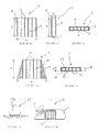
- one embodiment of a sustainable urban drainage system for a tiled or paved flooring comprises a plurality of paving stones 1 laid side by side in a spaced relationship on a supporting surface and a plurality of devices 2 disposed in gaps 3 therebetween, the paving stones 1 being secured in place by filling the gaps 3 with a wet (e.g. cement mortar) or dry (e.g. sand) jointing material.
- the stones 1 can sit on a bed of sand or textile material if required and can be any desired shape and laid in any pattern or arrangement.
- Each device 2 as shown in figures 2a - 2c , comprises a substantially hollow rectangular body 4, which is divided internally, into a plurality of open-ended channels 5, by a number of partition walls 6, which each extend between opposing side walls 7, 8 of the body 4.
- the channels 5, allow water to drain from a top surface of the paving stones through the device 2 into the ground, thereby reducing surface flooding.
- Figures 3a and 3b show an alternatively shaped device 9, which comprises a substantially wedge-shaped body 10, e.g. a trapezoid, which is also divided internally, into a plurality of open-ended channels 11, by a number of partition walls 12, which extend between opposing side walls 13, 14 of the body 10.
- This type of device 9 is placed between the stones 1 with the wide end directed downwardly towards the supporting surface, so that when the gaps 3 have been filled with mortar, the devices 9 are more difficult to remove.
- the devices 2, 9 are constructed of a recycled or non-recycled plastics material and are formed using any suitable method, e.g. extrusion, although any other suitable material and construction method could be used.
- a textile device e.g. a device comprising a textile material, which comprises woven, non-woven or knitted permeable sheets.
- Such a device can be formed from recycled materials.
- Geotextiles such as geo-membranes, geo-grids, and geo-matrices, which are permeable to water are suitable materials for such devices.
- a textile device of this kind allows water to permeate therethrough.
- the width Y is of each device is approximately 5mm - 12 mm, although widths of approximately 8 mm, 9 mm and 10 mm are preferred.
- the devices 2, 9 are placed between the paving stones 1 at intervals, so that the channels 5, 11 are orientated substantially vertically. Where a textile device is used, the orientation of the device may not matter.
- the remaining gaps 3 are filled with wet or dry jointing material as discussed above.
- a geo-textile device is advantageous by providing a compressible unit, which allows for some variance in the joint gap sizes, without the need for different sizes of the device.
- the devices 2, 9 are installed with a minimum of 3 per m 2 (square meter).
- a blocking device 15 can be used, as shown in figures 4a-4b .
- the blocking device 15 comprises a handle 15a and a number of plugs 15b, which cooperate with the channels 5, 11 in use and are therefore of an appropriate size and distance from one another accordingly.
- plugs 15b engage with the channels 5, 11 whilst the wet or dry mortar is being applied to the surrounding gaps 3, as shown in figure 4b .
- the blocking device 50 comprises a moulded elongate body 51, which is substantially the same length as the drainage device 2, 9.
- the body 51 comprises opposing elongate side faces 52, end faces 53, a base 54 and an upper surface 55.
- the opposing side faces 52 taper outwardly towards the upper surface to provide overhanging flanges 56, which taper to a point.
- the side faces 52 further comprise a plurality of resiliently deflectable protrusions 57. These protrusions 57 extend from the side faces 52 and comprise free edges, which are directed towards the upper surface 55 of the blocking device 50.
- the protrusions 57 are fin-like and are tapered to decrease in thickness towards the free edges.
- the protrusions 57 are provided in pairs, with one of the pair being disposed above the other and are provided continuously or intermittently along the side faces 52 of the device 50.
- the blocking device 50 When the blocking device 50 is pushed between the pavers, the free ends of the protrusions 57 are deflected towards the body portion 51. Once in place, the upper surface 55 is substantially flush with the top surface of the adjacent pavers with the overhanging flanges 56 resting on an edge portion of each adjacent paver, like a temporary cap.
- the protrusions 57 grip the side walls of the pavers to prevent accidental dislocation.
- blocking means can be used to prevent the channels 5, 11 from being blocked during mortaring and this comprises a tape (not shown), which stretches across one open end of the channels to act as a temporary seal.
- the tape is biodegradable and/or water soluble for minimum impact on the environment and reduction of labour, e.g. having to remove each tape individually once mortaring is complete.
- the tape is either supplied with the devices 2, 9 as a separate component or is already applied to the devices 2, 9 covering one open end (an upwardly facing open end) of each device 2, 9. When the geo-textile is used, no blocking device is required.
- the device 15, 50 is removed and can be used elsewhere with another device 2, 9, or discarded, or recycled for re-use.
- the retaining block 16 comprises a body 16b shaped like a drainage device 2, and a handle 16a.
- the body 16b is placed in an appropriate gap 3 prior to mortaring and acts to retain a space in the mortar.
- the block 16 can be removed from the gap 3, for installation of the appropriate device 2, or the dry mortar mix can be simply left to set off in contact with moisture, leaving an appropriate void or channel to direct water into the ground rather than as run-off water.
- the space can receive an alternatively shaped device 9, although this would not be ideal, as the device 9 would not be secure without further mortaring or another means of securing being applied subsequently.
- the blocking device 15 and/or the retaining block 16 can be formed from brightly coloured plastics to facilitate identification of the location of these devices once mortaring is complete, to ensure that removal of the devices is efficient.
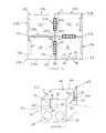
- a sustainable urban drainage system for a tiled or paved flooring comprises a plurality of integrated pavers 17 laid side by side in a spaced relationship on a supporting surface and a plurality of devices 2, 9 disposed in gaps 18 provided between the integrated pavers 17.
- Each integrated paver 17 comprises a thin fascia or paving stone 19 and a block 20, e.g. a breeze block or concrete aggregate backing as an overall laminated product.
- the block 20 of each paver 17 comprises a pair of open-ended conduits 21 which extend from one end of the paver to an opposite end.
- the conduits 21 are disposed side-by-side, although it will be appreciated that this is not a necessity and they could be provided at different levels and/or they could be disposed perpendicularly to one another for additional flexibility, although it will be appreciated that on a sloped surface, care should be taken to ensure that the conduits do not direct water directly down the slope. Furthermore, the conduits 21 could meet at an intersection.
- the conduits 21 are circular in cross-section, although this is not a functionally limiting feature and it will be appreciated that the conduits 21 could be any cross-sectional shape, e.g. square.
- the circular cross-section improves load-bearing strength relative to most other cross-sectional shapes.
- each paver 17 When installed, each paver 17 is disposed adjacent to a like paver 17, to provide a vertical passage or joint gap 24 for water to travel down to the conduits 21.
- the passage 24 is wide enough for a device 2, 9 to be disposed therein.
- the pavers 17 are to be installed on a sloped surface, the pavers 17 should be laid so that the conduits 21 direct the flow of water across the slope, as opposed to down the slope, to control the rate of flow of water down the slope and prevent or minimize localized flooding at the bottom of the slope.
- the block 20 comprises an outcrop or protruding step on each face having an open end of a conduit 21, the step being provided at conduit 21 floor level 21a, or the floor level 21a of the lowest disposed conduit 21.
- each step of a paver 17 abuts the step of an adjacent paver 17, to provide a base wall for the vertical passage 24.
- the base wall guides a major proportion of water travelling down the passage 24, into the conduits 21.
- the block 20 and the fascia 19 are sized relatively to one another so that the fascia 19 is disposed on the block 20 to provide a small peripheral rim 25 therearound.
- the peripheral rim 25 provides support means between the pavers 17 for a device 2, 9 to sit upon, so the devices 2, 9 are disposed between adjacent fascias 19 of adjacent units 17.
- Each peripheral rim 25 is of a width suitable to ensure that an edge 7/13, 8/14 of a device 2, 9 can be supported thereby.
- a suitable depth of the rim 25 is approximately 2mm (Y) and the rims 25 are disposed at a distance of approximately 8mm from one another, to provide a gap of approximately 12mm between the fascias 19 to easily receive a device 2, 9 of approximately 10mm in width.
- the pavers 17 and the devices 2, 9 can be manufactured to any suitable dimension, bearing in mind the preferential small channel 5, 11 dimensions of a device 2, 9 to avoid interference to persons, e.g. through a shoe heel becoming jammed in the channels.
- the pavers 17 are secured in place by filling the joint gaps 18 with a wet (e.g. cement mortar) or dry (e.g. sand) jointing material.
- a wet e.g. cement mortar
- dry e.g. sand
- FIG. 6c The passage of water through a sustainable drainage system according to the second embodiment of the invention is shown in figure 6c .
- the pavers 17 When the pavers 17 are laid in side-by-side arrangement with the devices 2, 9 disposed in the gaps 18, by sitting on spaced-apart adjacent rims 25, water can pass from a surface of the fascias 19, through the channels 5, 11 (or membranes) of a device 2, 9 (or textile) into the passage 24 and into the conduits 21. Once in the conduits 21, the water can be stored there and/or the water can drain away into the ground water in due course.
- a paving unit 25 ( figures 7a and 7b ) comprises a substantially cuboidal block having a pair of open-ended conduits 27, which extend from one end of the block to an opposite end thereof, as described above in relation to figures 6a and 6b .
- the unit 25 comprises a recess 28 (a) - (d) in each side wall 26 (a) - (d).
- the recess is open at the upper end 32 where it meets the upper surface 30 and is centrally located with respect to its edge thereof and extends from the upper surface edge nearly half way down the respective side wall 26(a) - (d) to terminate in a ledge 34 defining the base wall of the recess.
- the ledge is located above the conduits 27.
- the ledge is parallel with the upper surface 30 of the paving unit and terminates at each end with the perpendicular edge walls (36, 38) of the recess, which co-extend from the ends of the ledge 34 to the upper surface 30.
- the back wall of the recess 40 is parallel with its respective side face 26 (a) - (d).
- two side faces 26(d), 126(b) of two separate units 25,.125 are abutted together with a thin gap 29 of approximately 1-2mm therebetween. This is a suitable width for dry jointing pavers, using sand.
- the two recesses 28(d), 128(b) of the respective side faces 26d form a rectangular-section open-topped cavity 42. If the units 25, 125, 225, 325 are to be installed on a sloped surface, the units 25, 125, 225, 325 should be laid so that the conduits 21 direct the flow of water across the slope, as opposed to down the slope.
- the cavity 42 has a length X, a width Y and a depth Z that are all slightly larger than the length X, the width Y and the depth Z of the drainage device 2,9 to be used therewith, such that the drainage device 2,9 can be slotted into close fitting engagement with the cavity 42 easily with the top of the inlet end of the device 2,9 being disposed just below (e.g. 2mm below) the fascia surface 30 of the respective units 25, 125.
- the cavity 42 would have a length X' of approximately 102 - 105mm, a width Y' of approximately 11 - 12mm and a depth Z' of approximately 102 - 105mm.
- each recess 28 would therefore be recessed by a width of approximately 5mm.
- the cavity 42 maintains access to the gap 29, which extends below the ledge 34 thereof. Therefore, the cavity 42 and the gap 29 disposed thereunder comprise a passageway 31 leading to the conduits 27 and into the ground below.
- the advantage of this arrangement is that the unit 25, 125, 225, 325 is preferable for use as dry (sand) jointed paving, because the small gaps 29 can be provided between the units 25, 125, 225, 325 whilst still accommodating the drainage devices 2,9.
- the installation of drainage devices 2,9, in a paved arrangement using this kind of paving unit is very efficient.
- the unit 25, 125, 225, 325 can comprise a laminated fascia layer comprising the fascia surface 30, 130, 230, 330 which could be a natural or man-made stone paver, cobble stone or the like and a separate drainage layer comprising the conduits such as 27.
- This arrangement would result in a less expensive unit 25 and can be made with materials suitable for the intended weight-bearing of the surface, i.e. a greater weight-bearing material may be used for the drainage layer if the surface will receive vehicles as opposed to just pedestrians.
- the entire unit 25, 125, 225, 325 can be formed from a single block of a natural or man-made stone paver, cobble stone or the like with the man-made paver being the most economically viable option.
Landscapes
- Engineering & Computer Science (AREA)
- Architecture (AREA)
- Civil Engineering (AREA)
- Structural Engineering (AREA)
- Road Paving Structures (AREA)
Applications Claiming Priority (2)
| Application Number | Priority Date | Filing Date | Title |
|---|---|---|---|
| GB0725136A GB0725136D0 (en) | 2007-12-24 | 2007-12-24 | Sustainable urban drainage device and system |
| GB0807573A GB2459645A (en) | 2008-04-25 | 2008-04-25 | Drainage device |
Publications (1)
| Publication Number | Publication Date |
|---|---|
| EP2075376A2 true EP2075376A2 (de) | 2009-07-01 |
Family
ID=40451356
Family Applications (1)
| Application Number | Title | Priority Date | Filing Date |
|---|---|---|---|
| EP20080172907 Withdrawn EP2075376A2 (de) | 2007-12-24 | 2008-12-24 | Vorrichtung und System zur nachhaltigen Stadtentwässerung |
Country Status (1)
| Country | Link |
|---|---|
| EP (1) | EP2075376A2 (de) |
Cited By (6)
| Publication number | Priority date | Publication date | Assignee | Title |
|---|---|---|---|---|
| WO2012114079A1 (en) * | 2011-02-25 | 2012-08-30 | Tuffbau Limited | Spacer and method for laying paver |
| GB2533918A (en) * | 2014-12-19 | 2016-07-13 | G-Tech Coper Ltd | Apparatus and method for covering a gap between copers |
| EP3284878A1 (de) * | 2016-08-18 | 2018-02-21 | Franz Leitner | Entwässerungsvorrichtung für fliesen |
| CN111143928A (zh) * | 2019-12-23 | 2020-05-12 | 上海朗绿建筑科技股份有限公司 | 一种可持续排水系统的参数设计方法、系统及存储介质 |
| CN114319557A (zh) * | 2022-02-28 | 2022-04-12 | 中建八局第二建设有限公司 | 一种渗透型隐蔽排水沟及其施工方法 |
| AT527640B1 (de) * | 2024-02-14 | 2025-03-15 | Leitner Franz | Entwässerungsvorrichtung für Platten |
-
2008
- 2008-12-24 EP EP20080172907 patent/EP2075376A2/de not_active Withdrawn
Cited By (8)
| Publication number | Priority date | Publication date | Assignee | Title |
|---|---|---|---|---|
| WO2012114079A1 (en) * | 2011-02-25 | 2012-08-30 | Tuffbau Limited | Spacer and method for laying paver |
| GB2533918A (en) * | 2014-12-19 | 2016-07-13 | G-Tech Coper Ltd | Apparatus and method for covering a gap between copers |
| EP3284878A1 (de) * | 2016-08-18 | 2018-02-21 | Franz Leitner | Entwässerungsvorrichtung für fliesen |
| CN111143928A (zh) * | 2019-12-23 | 2020-05-12 | 上海朗绿建筑科技股份有限公司 | 一种可持续排水系统的参数设计方法、系统及存储介质 |
| CN114319557A (zh) * | 2022-02-28 | 2022-04-12 | 中建八局第二建设有限公司 | 一种渗透型隐蔽排水沟及其施工方法 |
| CN114319557B (zh) * | 2022-02-28 | 2024-01-12 | 中建八局第二建设有限公司 | 一种渗透型隐蔽排水沟及其施工方法 |
| AT527640B1 (de) * | 2024-02-14 | 2025-03-15 | Leitner Franz | Entwässerungsvorrichtung für Platten |
| AT527640A4 (de) * | 2024-02-14 | 2025-03-15 | Leitner Franz | Entwässerungsvorrichtung für Platten |
Similar Documents
| Publication | Publication Date | Title |
|---|---|---|
| EP2075376A2 (de) | Vorrichtung und System zur nachhaltigen Stadtentwässerung | |
| US8282310B2 (en) | Paver installation system | |
| TW454439U (en) | Mat for cultivating plant and device for laying such a mat | |
| US20250223764A1 (en) | Permeable Paving System | |
| JP5140384B2 (ja) | 雨水貯留装置とその施工方法 | |
| KR101835881B1 (ko) | 투수성 보도블록 | |
| KR101625658B1 (ko) | 개구형 산마루 측구 및 시공방법 | |
| GB2459645A (en) | Drainage device | |
| EP1947243B1 (de) | Belag | |
| KR101282096B1 (ko) | 투수성 보도블록 침하방지 구조 | |
| CN108221545B (zh) | 一种透水砖路面结构及其施工工艺 | |
| JP5263698B2 (ja) | 雨水貯留施設 | |
| KR200324301Y1 (ko) | 조립식 포장부재 블록 세트 | |
| US7000884B2 (en) | Paving system | |
| CN211571249U (zh) | 一种用于海绵城市的储水透水路面 | |
| KR100528363B1 (ko) | 조립식 포장부재 블록 세트 | |
| KR100712404B1 (ko) | 보도블록 시공 보조장치 | |
| JP2008266989A (ja) | 保水性舗装の形成方法 | |
| KR20090035142A (ko) | 잔디보호 블록 | |
| CN207277173U (zh) | 桥台台背填土内嵌式刚性透水板 | |
| KR100712403B1 (ko) | 보도블록 시공 보조장치 및 시공방법 | |
| JP7745372B2 (ja) | トラフ体及び、該トラフ体を用いたケーブル類の地中化方法 | |
| KR100970779B1 (ko) | 식재형 경계석용 받침대 | |
| KR20130122418A (ko) | 투수성 포장재의 침투량 증대장치 | |
| JP2622897B2 (ja) | 壁体の施工法および壁体背面土の排水方法 |
Legal Events
| Date | Code | Title | Description |
|---|---|---|---|
| PUAI | Public reference made under article 153(3) epc to a published international application that has entered the european phase |
Free format text: ORIGINAL CODE: 0009012 |
|
| AK | Designated contracting states |
Kind code of ref document: A2 Designated state(s): AT BE BG CH CY CZ DE DK EE ES FI FR GB GR HR HU IE IS IT LI LT LU LV MC MT NL NO PL PT RO SE SI SK TR |
|
| AX | Request for extension of the european patent |
Extension state: AL BA MK RS |
|
| STAA | Information on the status of an ep patent application or granted ep patent |
Free format text: STATUS: THE APPLICATION IS DEEMED TO BE WITHDRAWN |
|
| 18D | Application deemed to be withdrawn |
Effective date: 20110701 |