EP2074914A1 - Elektrisches Haushaltsgerät - Google Patents
Elektrisches Haushaltsgerät Download PDFInfo
- Publication number
- EP2074914A1 EP2074914A1 EP08106024A EP08106024A EP2074914A1 EP 2074914 A1 EP2074914 A1 EP 2074914A1 EP 08106024 A EP08106024 A EP 08106024A EP 08106024 A EP08106024 A EP 08106024A EP 2074914 A1 EP2074914 A1 EP 2074914A1
- Authority
- EP
- European Patent Office
- Prior art keywords
- maintenance
- housing
- cover
- opening
- connecting wall
- Prior art date
- Legal status (The legal status is an assumption and is not a legal conclusion. Google has not performed a legal analysis and makes no representation as to the accuracy of the status listed.)
- Granted
Links
- 238000012423 maintenance Methods 0.000 claims abstract description 75
- XLYOFNOQVPJJNP-UHFFFAOYSA-N water Substances O XLYOFNOQVPJJNP-UHFFFAOYSA-N 0.000 claims description 15
- 238000007373 indentation Methods 0.000 description 15
- 238000010276 construction Methods 0.000 description 5
- 230000001419 dependent effect Effects 0.000 description 2
- 238000011161 development Methods 0.000 description 2
- 230000018109 developmental process Effects 0.000 description 2
- 238000009413 insulation Methods 0.000 description 2
- 238000004519 manufacturing process Methods 0.000 description 2
- 230000003014 reinforcing effect Effects 0.000 description 2
- FYYHWMGAXLPEAU-UHFFFAOYSA-N Magnesium Chemical compound [Mg] FYYHWMGAXLPEAU-UHFFFAOYSA-N 0.000 description 1
- 230000015572 biosynthetic process Effects 0.000 description 1
- 230000001627 detrimental effect Effects 0.000 description 1
- 230000000694 effects Effects 0.000 description 1
- 230000007613 environmental effect Effects 0.000 description 1
- 238000010438 heat treatment Methods 0.000 description 1
- 230000002093 peripheral effect Effects 0.000 description 1
- 230000008092 positive effect Effects 0.000 description 1
- 238000007789 sealing Methods 0.000 description 1
Images


Classifications
-
- A—HUMAN NECESSITIES
- A47—FURNITURE; DOMESTIC ARTICLES OR APPLIANCES; COFFEE MILLS; SPICE MILLS; SUCTION CLEANERS IN GENERAL
- A47J—KITCHEN EQUIPMENT; COFFEE MILLS; SPICE MILLS; APPARATUS FOR MAKING BEVERAGES
- A47J27/00—Cooking-vessels
- A47J27/21—Water-boiling vessels, e.g. kettles
- A47J27/21166—Constructional details or accessories
-
- A—HUMAN NECESSITIES
- A47—FURNITURE; DOMESTIC ARTICLES OR APPLIANCES; COFFEE MILLS; SPICE MILLS; SUCTION CLEANERS IN GENERAL
- A47J—KITCHEN EQUIPMENT; COFFEE MILLS; SPICE MILLS; APPARATUS FOR MAKING BEVERAGES
- A47J27/00—Cooking-vessels
- A47J27/21—Water-boiling vessels, e.g. kettles
- A47J27/21008—Water-boiling vessels, e.g. kettles electrically heated
Definitions
- the present invention relates to a household electric appliance, in particular a hot water storage, which has a housing and a maintenance and repair cover connected to the housing in a removable manner for closing an opening, wherein the maintenance and repair cover has a connecting wall projecting in the direction of the housing has to connect the maintenance and repair cover to the housing.
- the CN 2508145 Y discloses the construction of a housing for a hot water tank, the housing having a round end cover, a check / maintenance and repair opening provided on the end cover, and an electrical element provided inside the housing.
- a round maintenance and repair cover is removably attached to the end cover.
- On the inner ring side wall of the end cover a circular ring-shaped recessed groove is provided, wherein the environmental edge of the maintenance and repair cover engages in the annular indentation groove.
- a plurality of protrusions are provided on the indentation groove of the maintenance and repair cover, and corresponding recesses are provided on the outer periphery sidewall of the maintenance and repair cover such that the edge of the maintenance and repair cover, after being encased in the annular indentation groove of the end cover of the Bulges is clamped.
- the maintenance and repair cover is connected to the end cover by bordering it with the indentation groove formed on the end cover, there is a limitation on the shape of the maintenance and repair cover according to the shape of the indentation groove of the end cover (normally with respect to the shape of the end cover) Opening). Because the maintenance and repair coverage is a factor in the appearance of the household electrical appliance, a monotonous form of service and repair coverage will be detrimental to the manufacturer's desired diversification (eg, diversification of appearance) of the products , Otherwise, the manufacturer must Higher production costs change the appearance of the products. For example, to accommodate various forms of maintenance and repair coverage, the manufacturer must develop various molds to make other parts to match the service and repair coverage. This concerns in particular the housing, which is in connection with the maintenance and repair cover.
- the object of the present invention is to provide a household appliance, in which the developer has more latitude in the design of the product, without requiring a significant increase in production costs is required.
- the household electrical appliance according to the invention builds on generic household appliances in that a connecting wall at least partially has a distance from the edge of the maintenance and repair cover.
- the present invention relates to a household electric appliance having a housing and a maintenance and repair cover connected to the housing in a detachable manner for closing an opening, the maintenance and repair cover has a connecting wall projecting in the direction of the housing to the Maintenance and repair cover to connect to the housing, characterized in that the connecting wall at least partially has a distance from the edge of the maintenance and repair cover.
- the connecting wall at least partially has a distance to the edge of the maintenance and repair cover, there is no restriction on the shape of the maintenance and repair cover according to the shape of the connecting wall more. Therefore, there is a relatively large choice in the form of the maintenance and repair coverage and the developers must in the Development or conception of the external appearance of the household electrical appliance is no longer limited by the form of the maintenance and repair cover. Therefore, even with various forms of maintenance and repair cover, the construction of the housing can be left unchanged.
- the housing has a recessed groove provided along the opening, wherein the connecting wall at least partially engages in the recessed groove.
- the connecting wall forms a closed ring.
- the connecting wall is at least partially straight.
- connecting wall has a first part which abuts against the edge of the opening is particularly advantageous.
- the connecting wall in each case has a second part and a third part connected to a first part, wherein the second part and third part run parallel to each other and are straight in the horizontal direction.
- the housing has a cable-connected opening and a cover provided in a removable manner to the housing for closing the opening, wherein the cover is connected to the housing independently of the maintenance and repair cover.
- the opening is continuously connected to the cable outlet opening provided on the housing for attachment of the cable, wherein the plane on which the opening is located is positioned perpendicular to the plane on which the cable outlet opening is located.
- the service and repair cover also has a wall which is between its own edge and the connecting wall and whose height is less than the connecting wall. In this way, the maintenance and repair cover can be connected even closer to the housing.
- the housing has a Einbuchtungsteil whose shape corresponds to the maintenance and repair cover and is used to hold the maintenance and repair cover.
- the depth of the indentation part substantially coincides with the thickness or depth of the maintenance and repair cover. In this way, a compact household electrical appliance with a clearly structured external appearance can be obtained.
- the domestic electrical appliance may in particular be a hot water appliance, preferably a hot water storage tank, which has a water storage tank and a heat insulation layer which is provided between the housing and the water tank.
- Fig.1 shows the partial three-dimensional representation of a household electrical appliance according to an advantageous embodiment of the present invention.
- the hot water tank 1 has a housing 2, a inside of housing 2 provided water tank (not shown) and located between water tank and housing 2 heat insulation layer (not shown) on.
- the housing 2 has a substantially cylindrically shaped container 20 with openings at both ends thereof and end caps 21 connected to the two ends of the container 20, respectively.
- a hanging part 3 is provided to attach the hot water tank 1 to a wall.
- the service and repair cover 6 is detachably attached to one of the end covers 21. Listed below is a concrete description of the end cover 21 with mounted maintenance and repair cover. 6
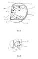
- Fig. 2 shows the three-dimensional representation of the end cover 21 with mounted maintenance and repair cover 6.
- Fig. 3 it is the three-dimensional representation of the end cover 21 with removed maintenance and repair cover 6.
- the end cover 21 has a bottom plate 22 and a border wall 23 which extends perpendicularly along the edge of the bottom plate 22.
- Several retaining plates 24 are provided along the inside of the skirting wall 23.
- an opening 4 is provided in the central area of end cover 21.
- the work / maintenance and repair personnel can inspect / service and repair the electrical element located within housing 2 - e.g. heating element, magnesium rod, computer field of the hot water tank 1.
- the opening 4 becomes one in a removable manner on the housing 2 provided maintenance and repair cover 6 closed (as in Fig. 1 and 2 shown).
- a narrow elongated indentation groove 12 is provided on the end cover 21 to fix the maintenance and repair cover 6.
- the recessed groove 12 is configured continuously but not closed.
- no indentation groove 12 is provided at the edge 40.
- the maintenance and repair cover 6 has a substantially plate shape, wherein the edge 10 has an arcuate portion and connected to the two ends of the arcuate portion connected rectilinear portion.
- the inside of the maintenance and repair cover 6 - ie the housing 2 side facing - has a connecting wall 8, which holds a certain distance to the edge 10 of the maintenance and repair cover 6.
- the connecting wall 8 has a first part 81, a hook part 80 as well as a second part 82 and third part 83 arranged in parallel with the first part 81.
- the height of the first part 81 is less than that of the second part and the third part 82, 83.
- the second part 82 and the third part 83 are straight in a horizontal direction, so that during assembly the maintenance and repair cover 6 through the second part 82 and the third part 83 and along the opening 4 of the end cover 21 can be fitted into the intended indentation groove 12 and ensures exactly that the hook part 80 can engage in the inner surface of the end cover 21.
- the connecting wall 8 also has corresponding to the first part 81 and provided with the second part 82 and third part 83 connected to the fourth part 84, wherein the fourth part 84 has an arcuate shape.
- the maintenance and repair cover 6 is connected to the end cover 21.
- the fitting via the located in the vicinity of the end of the first part 81 second part 82 and third part 83 at the corresponding location of the recessed groove 12, the fitting, so that the first part 81 located hook portion 80 through the opening 4 in the inner Surface of end cover 21 while the first part 81 abuts against the edge 40 of opening 4.
- the maintenance and repair cover 6 with the edge 40 of opening 4 as an axis make a rotational movement at a certain angle.
- the second part, third part and fourth part 82, 83, 84 of connecting wall 8 are received in the indentation groove 12.
- connecting wall 8 abuts against the edge 40 of opening 4, while the remaining part in the narrow elongated indentation groove 12 engages, so that the maintenance and repair cover. 6 is reliably positioned on the housing 2 and at the same time a fairly good sealing effect is effected.
- a wall 25 whose height is lower than that of the connecting wall 8, with the wall 25 fitting into the narrow groove 31 provided on the end cover 21, so that the Maintenance and repair cover 6 can be reliably connected to the housing 2.
- a recess portion 26 corresponding in shape to the maintenance and repair cover 6 is provided on the end cover 21 for receiving the maintenance and repair cover 6. It is even more optimal if the depth of the indentation part 26 coincides with the thickness or depth of the maintenance and repair cover 6, so that the maintenance and repair cover 6 is in one plane with the other parts of the end cover 21. This is advantageous from an aesthetic point of view.
- a plurality of reinforcing ribs 27 are formed on the inside of the maintenance and repair cover 6 .
- a connection structure 28 for fixing a circuit board (not shown) is also provided to fix the circuit board to the inside of the maintenance and repair cover 6.
- one end is connected to the circuit board, while the other end with the cable connected to the control switch is led out of the inside of the housing 2 through the cable duct 14 provided on the end cover 21.
- the cable can be held in the cable duct 14.
- the cable outlet opening 14 is closed when the cable does not have to be routed out of the housing 2 through the cable outlet opening 14, and the cable outlet opening 14 is opened when the cable has to be routed out of the housing 2 through the cable outlet opening 14.
- the cable duct opening is provided on the peripheral wall 23 of the end cover 21.
- an opening 16 is provided with continuous connection to the cable duct opening 14 so that the cable duct opening 14 provides an open construction and the cable can be conveniently pushed into the cable duct opening 14.
- the opening 16 is covered by a cover 18 removably connected to the end cover 21. At the same time, one side of the cover 18 presses the cable so that the cable is secured by the holding force between itself and the cable discharge opening 14 and through the cover 18.
- the cover 18 is attached to the end cover 21 independently of the maintenance and repair cover 6, so that it is not necessary to first remove the cover 18 to remove the maintenance and repair cover 6 or to first remove the maintenance and repair cover 6 to remove the cover 18 can.
- a support wall 29 is provided, which extends parallel to the bottom plate 22 from the inside of the surrounding wall 21 of the end cover 21 forth, wherein on the support wall 29, a receiving base 30 is formed, which with screws (not shown ) of the cover 18 can be attached.
- the second part, third part and fourth part 82, 83, 84 of the connecting wall 8 are enclosed within the recessed groove 12 on the housing 2, while the first part 81 abuts against an edge of the opening 4.
- the present invention is not limited thereto. All parts of the connecting wall 8 can be enclosed in the indentation groove 12 or all parts can butt against the edge of the opening 4.
- the connecting wall 8 to the edge 10 of the maintenance and repair cover 6 at a certain distance.
- the present invention is not limited thereto.
- a distance may be maintained between a portion of the connecting wall 8 and the edge 10 of the service and repair cover 6, while another portion may protrude beyond the edge 10 of the service and repair cover.
Landscapes
- Engineering & Computer Science (AREA)
- Food Science & Technology (AREA)
- Housings, Intake/Discharge, And Installation Of Fluid Heaters (AREA)
- Casings For Electric Apparatus (AREA)
- Cookers (AREA)
- Induction Heating Cooking Devices (AREA)
- Heat-Pump Type And Storage Water Heaters (AREA)
Abstract
Description
- Die vorliegende Erfindung betrifft ein elektrisches Haushaltsgerät, insbesondere einen Warmwasserspeicher, welches ein Gehäuse sowie eine mit dem Gehäuse in abnehmbarer Art und Weise verbundene Wartungs- und Reparaturabdeckung zum Schließen einer Öffnung aufweist, wobei die Wartungs- und Reparaturabdeckung eine in Richtung auf das Gehäuse vorstehende Verbindungswand aufweist, um die Wartungs- und Reparaturabdeckung mit dem Gehäuse zu verbinden.
- Die
CN 2508145 Y offenbart die Konstruktion eines Gehäuses für einen Warmwasserspeicher, wobei das Gehäuse eine runde Endabdeckung, eine auf der Endabdeckung vorgesehene Öffnung für Überprüfung/Wartung und Reparatur sowie ein innerhalb des Gehäuses vorgesehenes elektrisches Element aufweist. Eine runde Wartungs- und Reparaturabdeckung wird in abnehmbarer Art und Weise an der Endabdeckung befestigt. An der inneren Ringseitenwand der Endabdeckung wird eine rundringförmige Einbuchtungsrille vorgesehen, wobei der Umgebungsrand der Wartungs- und Reparaturabdeckung in die rundringförmige Einbuchtungsrille einfasst. Gleichzeitig werden an der Einbuchtungsrille der Wartungs- und Reparaturabdeckung mehrere Ausbuchtungen vorgesehen und an der äußeren Umgebungsseitenwand der Wartungs- und Reparaturabdeckung werden in diesen Ausbuchtungen entsprechende Aussparungen vorgesehen, so dass der Rand der Wartungs- und Reparaturabdeckung nach Einfassen in die rundringförmige Einbuchtungsrille der Endabdeckung von den Ausbuchtungen festgeklemmt wird. - Weil die Wartungs- und Reparaturabdeckung durch Einfassen ihres Randes in die an der Endabdeckung gebildeten Einbuchtungsrille mit der Endabdeckung verbunden wird, besteht hinsichtlich der Auswahl der Form der Wartungs- und Reparaturabdeckung eine Beschränkung entsprechend der Form der Einbuchtungsrille der Endabdeckung (normalerweise mit Bezug zur Form der Öffnung). Weil es sich bei der Wartungs- und Reparaturabdeckung um einen Faktor für das äußere Erscheinungsbild des elektrischen Haushaltsgerätes handelt, wirkt sich eine monotone Form der Wartungs- und Reparaturabdeckung in Hinblick auf eine vom Hersteller angestrebte Diversifizierung (beispielsweise Diversifizierung des äußeren Erscheinungsbildes) der Produkte ungünstig aus. Anderenfalls muss der Hersteller durch höhere Herstellungskosten das äußere Erscheinungsbild der Produkte verändern. Um beispielsweise verschiedenen Formen der Wartungs- und Reparaturabdeckung zu entsprechen, muss der Hersteller verschiedene Gussformen entwickeln, um andere Teile passend zu der Wartungs- und Reparaturabdeckung herzustellen. Dies betrifft insbesondere das Gehäuse, welches in Verbindung mit der Wartungs- und Reparaturabdeckung steht.
- Somit ergibt sich die Aufgabe der vorliegenden Erfindung ein Haushaltsgerät bereitzustellen, bei welchem der Entwickler mehr Spielraum bei der Konzeption des Produktes hat, ohne dass hierfür eine signifikante Steigerung der Herstellungskosten erforderlich ist.
- Diese Aufgabe wird durch ein elektrisches Haushaltsgerät mit den Merkmalen des unabhängigen Anspruches gelöst. Vorteilhafte Aus- und Weiterbildungen, welche einzeln oder in Kombination miteinander eingesetzt werden können, sind Gegenstand der abhängigen Ansprüche.
- Das erfindungsgemäße elektrische Haushaltsgerät baut auf gattungsgemäßen Haushaltsgeräten dadurch auf, dass eine Verbindungswand zumindest teilweise einen Abstand zum Rand der Wartungs- und Reparaturabdeckung aufweist.
- Die vorliegende Erfindung betrifft ein elektrisches Haushaltsgerät, welches ein Gehäuse sowie eine mit dem Gehäuse in abnehmbarer Art und Weise verbundene Wartungs- und Reparaturabdeckung zum Schließen einer Öffnung aufweist, wobei die Wartungs- und Reparaturabdeckung eine in Richtung auf das Gehäuse vorstehende Verbindungswand aufweist, um die Wartungs- und Reparaturabdeckung mit dem Gehäuse zu verbinden, dadurch gekennzeichnet, dass die Verbindungswand zumindest teilweise einen Abstand zum Rand der Wartungs- und Reparaturabdeckung aufweist.
- Da die Verbindungswand zumindest teilweise einen Abstand zum Rand der Wartungs- und Reparaturabdeckung aufweist, besteht in Hinblick auf die Form der Wartungs- und Reparaturabdeckung keine Beschränkung entsprechend der Form der Verbindungswand mehr. Daher besteht eine relativ große Auswahl bezüglich der Form der Wartungs- und Reparaturabdeckung und die Entwickler müssen bei der Entwicklung bzw. Konzeption des äußeren Erscheinungsbildes des elektrischen Haushaltsgerätes keine Beschränkungen mehr wegen der Form der Wartungs- und Reparaturabdeckung beachten. Daher kann auch bei verschiedenen Formen der Wartungs- und Reparaturabdeckung die Konstruktion des Gehäuses unverändert gelassen werden.
- Vorteilhafte Ausgestaltungen der vorliegenden Erfindung sind Gegenstand der abhängigen Ansprüche, welche einzeln oder in Kombination miteinander eingesetzt werden können.
- In einer bevorzugten Ausführung der vorliegenden Erfindung weist das Gehäuse eine entlang der Öffnung vorgesehene Einbuchtungsrille auf, wobei die Verbindungswand zumindest teilweise in die Einbuchtungsrille einfasst. Auf diese Weise kann die Wartungs- und Reparaturabdeckung zuverlässig mit dem Gehäuse verbunden werden und gleichzeitig besteht ein positiver Effekt in Hinblick auf die Bildung einer Dichtung zwischen Gehäuse und Wartungs- und Reparaturabdeckung.
- Besonders vorteilhaft ist es, wenn die Verbindungswand einen geschlossenen Ring bildet.
- Vorzugsweise ist die Verbindungswand zumindest teilweise gerade.
- Besonders vorteilhaft ist es, wenn die Verbindungswand einen ersten Teil aufweist, welcher gegen den Rand der Öffnung stößt.
- Bei einem besonders vorteilhaften Ausführungsbeispiel der vorliegenden Erfindung weist die Verbindungswand jeweils einen mit einem ersten Teil verbundenen zweiten Teil und dritten Teil auf, wobei der zweite Teil und dritte Teil parallel zueinander verlaufen und in waagerechter Richtung gerade sind.
- Gemäß einem vorteilhaften Ausführungsbeispiel der vorliegenden Erfindung weist das Gehäuse eine mit Kabel verbundener Öffnung sowie eine in abnehmbarer Art und Weise an das Gehäuse vorgesehene Abdeckung zum Verschließen der Öffnung auf, wobei die Abdeckung unabhängig von der Wartungs- und Reparaturabdeckung mit dem Gehäuse verbunden wird. Da Montage und Demontage von Wartungs- und Reparaturabdeckung und Abdeckung unabhängig voneinander erfolgen, ist es beim Öffnen der Wartungs- und Reparaturabdeckung durch das Wartungs- und Reparaturpersonal zwecks Durchführung einer Überprüfung nicht erforderlich, die mit den Kabeln verbundene Abdeckung zu öffnen, was die Überprüfungsarbeiten vereinfacht.
- Bevorzugt ist die Öffnung mit der am Gehäuse zwecks Befestigung der Kabel vorgesehenen Kabelausführungsöffnung durchgängig verbunden, wobei die Ebene, auf welcher sich die Öffnung befindet, senkrecht zu der Ebene, auf welcher sich die Kabelausführungsöffnung befindet, positioniert ist.
- Vorzugsweise weist die Wartungs- und Reparaturabdeckung kann außerdem eine Wand auf, welche sich zwischen dem eigenen Rand und der Verbindungswand befindet und deren Höhe geringer als die Verbindungswand ist. Auf diese Weise kann die Wartungs- und Reparaturabdeckung noch näher mit dem Gehäuse verbunden werden.
- Gemäß einem vorteilhaften Ausführungsbeispiel der vorliegenden Erfindung weist das Gehäuse ein Einbuchtungsteil auf, dessen Form der Wartungs- und Reparaturabdeckung entspricht und für die Aufnahme der Wartungs- und Reparaturabdeckung dient.
- Besonders vorteilhaft ist es, wenn die Tiefe des Einbuchtungsteils mit der Dicke bzw. Tiefe der Wartungs- und Reparaturabdeckung im Wesentlichen übereinstimmt. Auf diese Weise kann ein kompaktes elektrisches Haushaltsgerät mit klar strukturiertem äußeren Erscheinungsbild erhalten werden.
- Bei dem elektrischen Haushaltsgerät kann es sich insbesondere um einen Warmwassergerät vorzugsweise einen Warmwasserspeicher handeln, welcher einen Wasserspeicherbehälter sowie eine Wärmeisolationsschicht aufweist, die zwischen Gehäuse und Wasserbehälter vorgesehen ist.
- Weitere vorteilhafte Ausgestaltungen werden nachfolgend an Hand der in der Zeichnung dargestellten Ausführungsbeispiele, auf welchen die Erfindung jedoch nicht beschränkt ist, näher beschrieben.
- Es zeigen schematisch:
- Fig. 1
- eine teilweise, dreidimensionale Darstellung eines Warmwassergeräts gemäß einem vorteilhaften Ausführungsbeispiel der vorliegenden Erfindung;
- Fig. 2
- die dreidimensionale Darstellung der in
Fig. 1 gezeigten Endabdeckung; - Fig. 3
- die dreidimensionale Darstellung der Endabdeckung bei abgenommener Wartungs- und Reparaturabdeckung aus einem anderen Betrachtungswinkel;
- Fig. 4
- die vergrößerte Darstellung eines Bereiches mit einer Ecke der Öffnung der Wartungs- und Reparaturabdeckung;
- Fig.5
- die dreidimensionale Darstellung der Wartungs- und Reparaturabdeckung; und
- Fig. 6
- die vergrößerte Darstellung des Bereiches der Öffnung mit Verbindung von Wartungs- und Reparaturabdeckung und Kabel.
- Bei der nachstehend aufgeführten detaillierten Beschreibung der vorteilhaften Ausführungsbeispiele weisen gleiche oder ähnliche Komponenten dieselben Bezugszeichen auf.
- Die in der vorstehenden Beschreibung, den Ansprüchen und den Zeichnungen offenbarten Merkmale können sowohl einzeln als auch in beliebiger Kombination für die Verwirklichung der Erfindung in ihren verschiedenen Ausgestaltungen von Bedeutung sein.
-
Fig.1 zeigt die teilweise dreidimensionale Darstellung eines elektrischen Haushaltsgerätes gemäß einem vorteilhaften Ausführungsbeispiel der vorliegenden Erfindung. Bei dem elektrischen Haushaltsgerät handelt es sich beispielsweise um einen Warmwasserspeicher 1. Es ist hervorzuheben, dass die vorliegende Erfindung keineswegs hierauf beschränkt ist, sondern dass die vorliegende Erfindung auch auf andere elektrische Haushaltsgeräte angewendet werden kann - beispielsweise auf elektrische Kühlschränke usw. Der Warmwasserspeicher 1 weist ein Gehäuse 2, einen innerhalb von Gehäuse 2 vorgesehenen Wasserbehälter (nicht dargestellt) sowie eine zwischen Wasserbehälter und Gehäuse 2 befindliche Wärmeisolationsschicht (nicht dargestellt) auf. Das Gehäuse 2 weist einen im Wesentlichen zylindrisch geformten Behälter 20 mit Öffnungen an seinen beiden Enden sowie jeweils mit den beiden Enden vom Behälter 20 verbundene Endabdeckungen 21 auf. An einer Seite vom Behälter 20 wird ein Hängeteil 3 vorgesehen, um den Warmwasserspeicher 1 an einer Wand zu befestigen. Die Wartungs- und Reparaturabdeckung 6 wird in abnehmbarer Art und Weise an einer der Endabdeckungen 21 angebracht. Nachstehend aufgeführt erfolgt eine konkrete Beschreibung der Endabdeckung 21 mit montierter Wartungs- und Reparaturabdeckung 6. -
Fig. 2 zeigt die dreidimensionale Darstellung der Endabdeckung 21 mit montierter Wartungs- und Reparaturabdeckung 6. Bei derFig. 3 handelt es sich um die dreidimensionale Darstellung der Endabdeckung 21 bei abgenommener Wartungs-und Reparaturabdeckung 6. Wie inFig. 2 gezeigt, weist die Endabdeckung 21 eine Bodenplatte 22 und eine Umrandungswand 23 auf, welche sich entlang des Randes von Bodenplatte 22 senkrecht erstreckt. Mehrere Halteplatten 24 werden entlang der Innenseite der Umrandungswand 23 vorgesehen. Nachdem die Endabdeckung 21 am Behälter 20 befestigt worden ist, wird das Ende der Seitenwand von Behälter 20 zwischen den Halteplatten 24 und der Innenseite der Umrandungswand 23 gehalten. - Wie in
Fig. 2 ,Fig. 3 und Fig. 4 gezeigt, wird in dem mittleren Bereich von Endabdeckung 21 eine Öffnung 4 vorgesehen. Durch die Öffnung 4 kann das Arbeits/Wartungs- und Reparaturpersonal das innerhalb von Gehäuse 2 befindliche elektrische Element überprüfen/warten und reparieren - beispielsweise Heizelement, Magnesiumstab, Computerfeld des Warmwasserspeichers 1. Unter normalen Umständen wird die Öffnung 4 von einer in abnehmbarer Art und Weise am Gehäuse 2 vorgesehenen Wartungs- und Reparaturabdeckung 6 verschlossen (wie inFig. 1 und 2 gezeigt). Entlang der Öffnung 4 wird an der Endabdeckung 21 eine schmale längliche Einbuchtungsrille 12 vorgesehen, um die Wartungs- und Reparaturabdeckung 6 zu befestigen. Bei dem vorliegenden Ausführungsbeispiel ist die Einbuchtungsrille 12 kontinuierlich aber nicht geschlossen ausgestaltet. Wie inFig. 4 gezeigt, wird am Rand 40 keine Einbuchtungsrille 12 vorgesehen. - Bei der
Fig. 5 handelt es sich um die dreidimensionale Darstellung der von der Endabdeckung 21 abgenommenen Wartungs- und Reparaturabdeckung 6. Wie inFig. 5 gezeigt, weist die Wartungs- und Reparaturabdeckung 6 im Wesentlichen eine Plattengestalt auf, wobei deren Rand 10 einen bogenförmigen Teil sowie mit den beiden Enden des bogenförmigen Teils verbundenen geradlinigen Teil aufweist. Die Innenseite von der Wartungs- und Reparaturabdeckung 6 - also die dem Gehäuse 2 zugewandte Seite - weist eine Verbindungswand 8 auf, welche einen bestimmten Abstand zum Rand 10 der Wartungs- und Reparaturabdeckung 6 hält. - Die Verbindungswand 8 weist einen ersten Teil 81, ein Hakenteil 80 sowie einen jeweils mit dem ersten Teil 81 verbundenen parallel angeordneten zweiten Teil 82 und dritten Teil 83 auf. Die Höhe des ersten Teils 81 ist geringer als die des zweiten Teils und dritten Teils 82, 83. Der zweite Teil 82 und der dritte Teil 83 sind in waagerechter Richtung gerade, so dass bei der Montage die Wartungs- und Reparaturabdeckung 6 durch den zweiten Teil 82 und den dritten Teil 83 und entlang der Öffnung 4 von Endabdeckung 21 in die vorgesehene Einbuchtungsrille 12 eingepasst werden kann und exakt dafür sorgt, dass das Hakenteil 80 in die innere Oberfläche von Endabdeckung 21 einfassen kann. Die Verbindungswand 8 weist außerdem entsprechend zum ersten Teil 81 vorgesehenes sowie einen mit dem zweiten Teil 82 und dritten Teil 83 verbundenen vierten Teil 84 auf, wobei der vierte Teil 84 eine Bogenform aufweist.
- Durch die Abstimmung der Konstruktion der Verbindungswand 8 und Endabdeckung 21 wird die Wartungs- und Reparaturabdeckung 6 mit der Endabdeckung 21 verbunden. Bei der Montage erfolgt über den in der Nähe vom Ende des ersten Teils 81 befindlichen zweiten Teil 82 und dritten Teil 83 an der entsprechenden Stelle der Einbuchtungsrille 12 die Einpassung, so dass das am ersten Teil 81 befindliche Hakenteil 80 durch die Öffnung 4 in die innere Oberfläche von Endabdeckung 21 einfasst, während der erste Teil 81 gegen den Rand 40 von Öffnung 4 stößt. Auf diese Weise kann die Wartungs- und Reparaturabdeckung 6 mit dem Rand 40 von Öffnung 4 als Achse eine Drehbewegung in einem bestimmten Winkel vornehmen. Anschließend werden der zweite Teil, dritte Teil und vierte Teil 82, 83, 84 von Verbindungswand 8 in der Einbuchtungsrille 12 aufgenommen. Ein Teil von Verbindungswand 8 stößt gegen den Rand 40 von Öffnung 4, während der übrige Teil in die schmale längliche Einbuchtungsrille 12 einfasst, so dass die Wartungs- und Reparaturabdeckung 6 zuverlässig am Gehäuse 2 positioniert wird und gleichzeitig ein recht guter Dichtungseffekt bewirkt wird. Vorzugsweise wird zwischen dem Rand 10 von Wartungs- und Reparaturabdeckung 6 und der Verbindungswand 8 außerdem eine Wand 25 vorgesehen, deren Höhe niedriger als die der Verbindungswand 8 ist, wobei die Wand 25 in die an Endabdeckung 21 vorgesehene schmale Rille 31 einfasst, so dass die Wartungs- und Reparaturabdeckung 6 zuverlässig mit dem Gehäuse 2 verbunden werden kann.
- Vorzugsweise wird an der Endabdeckung 21 ein in seiner Form der Wartungs- und Reparaturabdeckung 6 entsprechendes Einbuchtungsteil 26 vorgesehen, um die Wartungs- und Reparaturabdeckung 6 aufzunehmen. Noch optimaler ist es, wenn die Tiefe des Einbuchtungsteils 26 mit der Dicke bzw. Tiefe der Wartungs- und Reparaturabdeckung 6 übereinstimmt, so dass die Wartungs- und Reparaturabdeckung 6 sich auf einer Ebene mit den anderen Teilen von Endabdeckung 21 befindet. Dies wirkt sich unter ästhetischem Gesichtspunkt vorteilhaft aus.
- An der Innenseite der Wartungs- und Reparaturabdeckung 6 werden mehrere Verstärkungsrippen 27 gebildet. An der Innenseite der Wartungs- und Reparaturabdeckung 6 wird außerdem eine Verbindungskonstruktion 28 zur Befestigung einer Stromkreisplatte (nicht dargestellt) vorgesehen, um die Stromkreisplatte an der Innenseite der Wartungs- und Reparaturabdeckung 6 zu befestigen. Wie in
Fig. 3 undFig. 6 gezeigt, wird ein Ende mit der Stromkreisplatte verbunden, während das andere Ende mit dem an den Steuerungsschalter angeschlossenen Kabel durch die an der Endabdeckung 21 vorgesehene Kabelausführungsöffnung 14 aus dem Inneren des Gehäuses 2 hinausgeführt wird. Durch eine angemessene Ausführung von Form und/oder Abmessungen von Kabelausführungsöffnung 14 und Kabel kann n das Kabel in n der Kabelausführungsöffnung 14 gehalten werden. Vorzugsweise wird die Kabelausführungsöffnung 14 geschlossen, wenn das Kabel nicht durch die Kabelausführungsöffnung 14 aus dem Gehäuse 2 hinausgeführt werden muss, und die Kabelausführungsöffnung 14 wird geöffnet, wenn das Kabel durch die Kabelausführungsöffnung 14 aus dem Gehäuse 2 hinausgeführt werden muss. - Die Kabelausführungsöffnung wird an der Umrandungswand 23 von Endabdeckung 21 vorgesehen. An der Bodenplatte 22 wird eine Öffnung 16 mit durchgängiger Verbindung zu der Kabelausführungsöffnung 14 vorgesehen, so dass die Kabelausführungsöffnung 14 eine offene Konstruktion bietet und das Kabel bequem in die Kabelausführungsöffnung 14 gedrückt werden kann. Die Öffnung 16 wird durch eine in abnehmbarer Art und Weise mit der Endabdeckung 21 verbundene Abdeckung 18 abgedeckt. Gleichzeit drückt eine Seite der Abdeckung 18 das Kabel fest, so dass das Kabel durch die Haltekraft zwischen sich selbst und der Kabelausführungsöffnung 14 sowie durch die Abdeckung 18 befestigt wird.
- Die Abdeckung 18 wird unabhängig von der Wartungs- und Reparaturabdeckung 6 an die Endabdeckung 21 angebracht, so dass es nicht erforderlich ist, zunächst die Abdeckung 18 abzunehmen, um die Wartungs- und Reparaturabdeckung 6 abnehmen zu können beziehungsweise zunächst die Wartungs- und Reparaturabdeckung 6 abzunehmen, um die Abdeckung 18 abnehmen zu können. Wie in
Abbildung 2 undAbbildung 6 gezeigt, wird an einer Position entsprechend der Öffnung 21 eine Stützwand 29 vorgesehen, welche sich parallel zu Bodenplatte 22 von der Innenseite der Umgebungswand 21 der Endabdeckung 21 her erstreckt, wobei an der Stützwand 29 ein Aufnahmesockel 30 gebildet wird, welcher mit Schrauben (nicht dargestellt) der Abdeckung 18 befestigt werden kann. - Bei dem vorstehend Ausführungsbeispiel werden der zweite Teil, dritte Teil und vierte Teil 82, 83, 84 der Verbindungswand 8 innerhalb der Einbuchtungsrille 12 am Gehäuse 2 eingefasst, während der erste Teil 81 gegen einen Rand der Öffnung 4 stößt. Allerdings ist die vorliegende Erfindung nicht hierauf beschränkt. Es können sämtliche Teile der Verbindungswand 8 in die Einbuchtungsrille 12 einfassen beziehungsweise können sämtliche Teile gegen den Rand der Öffnung 4 stoßen.
- Bei dem vorstehenden Ausführungsbeispiel weist außerdem die Verbindungswand 8 zu dem Rand 10 der Wartungs- und Reparaturabdeckung 6 einen bestimmten Abstand auf. Allerdings ist die vorliegende Erfindung hierauf nicht beschränkt. Beispielsweise kann bei anderen Ausführungsbeispielen zwischen einem Teil der Verbindungswand 8 und dem Rand 10 der Wartungs- und Reparaturabdeckung 6 ein Abstand gehalten werden, während ein anderer Teil über den Rand 10 der Wartungs- und Reparaturabdeckung hervorstehen kann.
-
- 1 Elektrisches Haushaltsgerät
- 2 Gehäuse
- 3 Hängeteil
- 4 Öffnung
- 6 Wartungs- und Reparaturabdeckung
- 8 Verbindungswand
- 80 Hakenteil
- 81 erster Teil
- 82 zweiter Teil
- 83 dritter Teil
- 84 vierter Teil
- 10 Rand der Verbindungswand 8
- 12 Einbuchtungsrille
- 14 Kabelausführungsöffnung
- 16 Öffnung
- 18 Abdeckung
- 20 Behälter
- 21 Endabdeckung
- 22 Bodenplatte
- 23 Umrandungswand
- 24 Halteplatte
- 25 Wand
- 26 Einbuchtungsteil
- 27 Verstärkungsrippen
- 28 Verbindungskonstruktion
- 29 Stützkonstruktion
- 30 Aufnahmesockel
- 31 Schmale Rille
- 40 Rand
Claims (12)
- Elektrisches Haushaltsgerät (1), welches ein Gehäuse (2, 20, 21) sowie eine mit dem Gehäuse (2, 20, 21) in abnehmbarer Art und Weise verbundene Wartungs- und Reparaturabdeckung (6) zum Schließen einer Öffnung (4) aufweist, wobei die Wartungs- und Reparaturabdeckung (6) eine in Richtung auf das Gehäuse (2, 20, 21) vorstehende Verbindungswand (8) aufweist, um die Wartungs- und Reparaturabdeckung (6) mit dem Gehäuse (2, 21) zu verbinden, dadurch gekennzeichnet, dass die Verbindungswand (8) zumindest teilweise einen Abstand zum Rand (10) der Wartungs- und Reparaturabdeckung (6) aufweist.
- Elektrisches Haushaltsgerät (1) gemäß Patentanspruch 1, dadurch gekennzeichnet, dass das Gehäuse (2, 21) eine entlang der Öffnung (4) vorgesehene Einbuchtungsrille (12) aufweist, wobei die Verbindungswand (8) zumindest teilweise in die Einbuchtungsrille (12) einfasst.
- Elektrisches Haushaltsgerät (1) nach einem der vorherigen Patentansprüche, dadurch gekennzeichnet, dass die Verbindungswand (8) einen geschlossenen Ring bildet.
- Elektrisches Haushaltsgerät (1) nach einem der vorherigen Patentansprüche, dadurch gekennzeichnet, dass die Verbindungswand (8) zumindest teilweise gerade ist.
- Elektrisches Haushaltsgerät (1) nach einem der vorherigen Patentansprüche, dadurch gekennzeichnet, dass die Verbindungswand (8) einen ersten Teil (81) aufweist, welcher gegen den Rand (40) der Öffnung (4) stößt.
- Elektrisches Haushaltsgerät (1) gemäß Patentanspruch 5, dadurch gekennzeichnet, dass die Verbindungswand (8) jeweils einen mit dem ersten Teil (81) verbundenen zweiten Teil (82) und dritten Teil (83) aufweist, wobei der zweite Teil (82) und dritte Teil (83) parallel zueinander und in waagerechter Richtung gerade sind.
- Elektrisches Haushaltsgerät (1) nach einem der vorherigen Patentansprüche, dadurch gekennzeichnet, dass das Gehäuse (2, 21) eine mit Kabel verbundene Öffnung (16) sowie eine in abnehmbarer Art und Weise an das Gehäuse (2, 21) vorgesehene Abdeckung (18) zum Verschließen der Öffnung (16) aufweist, wobei die Abdeckung (18) unabhängig von der Wartungs- und Reparaturabdeckung (6) mit dem Gehäuse (2, 21) verbunden wird.
- Elektrisches Haushaltsgerät (1) gemäß Patentanspruch 7, dadurch gekennzeichnet, dass die Öffnung (16) mit der am Gehäuse (2, 21) zwecks Befestigung der Kabel vorgesehenen Kabelausführungsöffnung (14) durchgängig verbunden ist, wobei die Ebene, auf welcher sich die Öffnung (16) befindet, senkrecht zu der Ebene, auf welcher sich die Kabelausführungsöffnung (14) befindet, positioniert ist.
- Elektrisches Haushaltsgerät (1) nach einem der vorherigen Patentansprüche, dadurch gekennzeichnet, dass die Wartungs- und Reparaturabdeckung (6) außerdem eine Wand (25) aufweist, welche sich zwischen dem eigenen Rand (10) und der Verbindungswand (8) befindet und deren Höhe geringer als die der Verbindungswand (8) ist.
- Elektrisches Haushaltsgerät (1) nach einem der vorherigen Patentansprüche, dadurch gekennzeichnet, dass das Gehäuse (2, 21) ein Einbuchtungsteil (26) aufweist, dessen Form der Wartungs- und Reparaturabdeckung (6) entspricht und der Aufnahme von der Wartungs- und Reparaturabdeckung (6) dient.
- Elektrisches Haushaltsgerät (1) nach Patentanspruch 10, dadurch gekennzeichnet, dass die Tiefe des Einbuchtungsteils (26) mit der Dicke bzw. Tiefe der Wartungs- und Reparaturabdeckung (6) im Wesentlichen übereinstimmt.
- Elektrisches Haushaltsgerät (1) nach einem der vorherigen Patentansprüche, dadurch gekennzeichnet, dass es sich bei dem elektrischen Haushaltsgerät (1) um einen Warmwasserspeicher (1) handelt, welcher einen Wasserspeicherbehälter sowie eine Wärmeisolationsschicht aufweist, die zwischen Gehäuse (2, 20, 21) und Wasserbehälter vorgesehen wird.
Applications Claiming Priority (1)
| Application Number | Priority Date | Filing Date | Title |
|---|---|---|---|
| CN200710302472A CN101472415B (zh) | 2007-12-25 | 2007-12-25 | 家用电器 |
Publications (2)
| Publication Number | Publication Date |
|---|---|
| EP2074914A1 true EP2074914A1 (de) | 2009-07-01 |
| EP2074914B1 EP2074914B1 (de) | 2012-02-22 |
Family
ID=40403970
Family Applications (1)
| Application Number | Title | Priority Date | Filing Date |
|---|---|---|---|
| EP08106024A Not-in-force EP2074914B1 (de) | 2007-12-25 | 2008-12-22 | Elektrisches Haushaltsgerät |
Country Status (4)
| Country | Link |
|---|---|
| EP (1) | EP2074914B1 (de) |
| CN (1) | CN101472415B (de) |
| AT (1) | ATE546071T1 (de) |
| RU (1) | RU2499960C2 (de) |
Citations (5)
| Publication number | Priority date | Publication date | Assignee | Title |
|---|---|---|---|---|
| DE2929177A1 (de) * | 1979-07-19 | 1981-02-05 | Bosch Siemens Hausgeraete | Haushaltsgeraet, insbesondere kuechenmaschine o.dgl. |
| DE3147992A1 (de) * | 1981-12-04 | 1983-06-16 | Robert Bosch Gmbh, 7000 Stuttgart | Abdeckkappe fuer oeffnungen in gehaeusen |
| WO1998058579A1 (en) * | 1997-06-23 | 1998-12-30 | Koninklijke Philips Electronics N.V. | Kitchen appliance having a drive unit adapted to be placed onto a container |
| CN2508145Y (zh) | 2001-06-08 | 2002-08-28 | 海尔集团公司 | 热水器端盖 |
| WO2007020161A1 (de) * | 2005-08-17 | 2007-02-22 | BSH Bosch und Siemens Hausgeräte GmbH | Stabmixer mit einem vormontageträger für einen motor und einen akku |
Family Cites Families (5)
| Publication number | Priority date | Publication date | Assignee | Title |
|---|---|---|---|---|
| DE3741466A1 (de) * | 1987-12-08 | 1989-06-22 | Columbus Profivac Gmbh | Elektrisch antreibbares reinigungsgeraet |
| US6446844B1 (en) * | 2001-12-18 | 2002-09-10 | Seaquist Closures Foreign, Inc. | Closure with internal flow control for a pressure openable valve in an extendable/retractable nozzle |
| KR100424580B1 (ko) * | 2001-12-20 | 2004-03-27 | 엘지전자 주식회사 | 진공청소기의 배기커버 체결장치 |
| RU2296702C1 (ru) * | 2005-08-30 | 2007-04-10 | Иностранное Унитарное Производственное Предприятие Компании "Белкапс Бетайлингус Гмбх" Белкэпс | Комбинация предохранительной крышки и контейнера |
| RU54748U1 (ru) * | 2006-01-18 | 2006-07-27 | Эдуард Сергеевич Прилуцкий | Электрический чайник |
-
2007
- 2007-12-25 CN CN200710302472A patent/CN101472415B/zh not_active Expired - Fee Related
-
2008
- 2008-12-22 AT AT08106024T patent/ATE546071T1/de active
- 2008-12-22 RU RU2008150511/06A patent/RU2499960C2/ru not_active IP Right Cessation
- 2008-12-22 EP EP08106024A patent/EP2074914B1/de not_active Not-in-force
Patent Citations (5)
| Publication number | Priority date | Publication date | Assignee | Title |
|---|---|---|---|---|
| DE2929177A1 (de) * | 1979-07-19 | 1981-02-05 | Bosch Siemens Hausgeraete | Haushaltsgeraet, insbesondere kuechenmaschine o.dgl. |
| DE3147992A1 (de) * | 1981-12-04 | 1983-06-16 | Robert Bosch Gmbh, 7000 Stuttgart | Abdeckkappe fuer oeffnungen in gehaeusen |
| WO1998058579A1 (en) * | 1997-06-23 | 1998-12-30 | Koninklijke Philips Electronics N.V. | Kitchen appliance having a drive unit adapted to be placed onto a container |
| CN2508145Y (zh) | 2001-06-08 | 2002-08-28 | 海尔集团公司 | 热水器端盖 |
| WO2007020161A1 (de) * | 2005-08-17 | 2007-02-22 | BSH Bosch und Siemens Hausgeräte GmbH | Stabmixer mit einem vormontageträger für einen motor und einen akku |
Also Published As
| Publication number | Publication date |
|---|---|
| CN101472415B (zh) | 2012-08-29 |
| RU2008150511A (ru) | 2010-06-27 |
| RU2499960C2 (ru) | 2013-11-27 |
| ATE546071T1 (de) | 2012-03-15 |
| EP2074914B1 (de) | 2012-02-22 |
| CN101472415A (zh) | 2009-07-01 |
Similar Documents
| Publication | Publication Date | Title |
|---|---|---|
| DE69404395T2 (de) | Anpassungsvorrichtung von einem elektrischen Mechanismus an einen elektrischen Kabelkanal | |
| EP2192659B1 (de) | Zinkdruckguss-Gehäuse für einen Steckverbinder | |
| EP1064707A1 (de) | Rahmengestell für einen schaltschrank | |
| DE8302614U1 (de) | Waschmaschine fuer den einbau in eine moebelanordnung | |
| DE102016116975A1 (de) | Zubereitungsgefäß für eine elektromotorisch betriebene Küchenmaschine | |
| DE102015103911A1 (de) | Elektronikeinheit eines Fluidsensors oder -ventils sowie Fluidsensor- oder Fluidventileinheit | |
| DE102020104994A1 (de) | Kabeleinlassvorrichtung für einen Schaltschrank sowie Anordnung und Verfahren zum Betrieb derselben | |
| DE1071104C2 (de) | Kühlschrank | |
| DE102009032055A1 (de) | Anordnung zum Verbinden zweier Elektroschränke und Elektroschrank zur Aufnahme von Elektroinstallationsgeräten | |
| EP2074915B1 (de) | Elektrisches Haushaltsgerät | |
| EP2074914B1 (de) | Elektrisches Haushaltsgerät | |
| DE102017108751A1 (de) | Wechselrichtereinrichtung | |
| EP0917276A1 (de) | Statorgehäuse für Elektromotoren | |
| EP3029787B1 (de) | Schaltschrankgehäuse und verfahren zur fertigung eines schaltschrankgehäuses | |
| DE19814741C1 (de) | Rahmengestell für einen Schaltschrank | |
| DE10160736B4 (de) | Hohlwanddose aus Kunststoff | |
| DE102019206287A1 (de) | Verschließvorrichtung | |
| DE3509311A1 (de) | Badewannenbatterie | |
| DE102008013725B3 (de) | Elektrisches Haustechnikgerät | |
| EP0952649A1 (de) | Schaltschrank mit einem Innen-Gehäuse zur HF-Abschirmung | |
| EP4421404B1 (de) | Gehäuse für einen durchlauferhitzer, elektrischer durchlauferhitzer sowie anordnung | |
| DE102016120712B4 (de) | Gehäuse zur Aufnahme einer Platine, Funktionselement | |
| DE20120003U1 (de) | Hohlwanddose aus Kunststoff | |
| DE102012103877A1 (de) | Deckel für ein Gargefäß sowie Gargefäß mit einem Deckel | |
| DE102019209140A1 (de) | Wasserkocher |
Legal Events
| Date | Code | Title | Description |
|---|---|---|---|
| PUAI | Public reference made under article 153(3) epc to a published international application that has entered the european phase |
Free format text: ORIGINAL CODE: 0009012 |
|
| AK | Designated contracting states |
Kind code of ref document: A1 Designated state(s): AT BE BG CH CY CZ DE DK EE ES FI FR GB GR HR HU IE IS IT LI LT LU LV MC MT NL NO PL PT RO SE SI SK TR |
|
| AX | Request for extension of the european patent |
Extension state: AL BA MK RS |
|
| 17P | Request for examination filed |
Effective date: 20100104 |
|
| 17Q | First examination report despatched |
Effective date: 20100201 |
|
| AKX | Designation fees paid |
Designated state(s): AT BE BG CH CY CZ DE DK EE ES FI FR GB GR HR HU IE IS IT LI LT LU LV MC MT NL NO PL PT RO SE SI SK TR |
|
| GRAP | Despatch of communication of intention to grant a patent |
Free format text: ORIGINAL CODE: EPIDOSNIGR1 |
|
| GRAS | Grant fee paid |
Free format text: ORIGINAL CODE: EPIDOSNIGR3 |
|
| GRAA | (expected) grant |
Free format text: ORIGINAL CODE: 0009210 |
|
| AK | Designated contracting states |
Kind code of ref document: B1 Designated state(s): AT BE BG CH CY CZ DE DK EE ES FI FR GB GR HR HU IE IS IT LI LT LU LV MC MT NL NO PL PT RO SE SI SK TR |
|
| REG | Reference to a national code |
Ref country code: GB Ref legal event code: FG4D Free format text: NOT ENGLISH |
|
| REG | Reference to a national code |
Ref country code: CH Ref legal event code: EP |
|
| REG | Reference to a national code |
Ref country code: AT Ref legal event code: REF Ref document number: 546071 Country of ref document: AT Kind code of ref document: T Effective date: 20120315 |
|
| REG | Reference to a national code |
Ref country code: IE Ref legal event code: FG4D Free format text: LANGUAGE OF EP DOCUMENT: GERMAN |
|
| REG | Reference to a national code |
Ref country code: DE Ref legal event code: R096 Ref document number: 502008006462 Country of ref document: DE Effective date: 20120419 |
|
| REG | Reference to a national code |
Ref country code: NL Ref legal event code: VDEP Effective date: 20120222 |
|
| LTIE | Lt: invalidation of european patent or patent extension |
Effective date: 20120222 |
|
| PG25 | Lapsed in a contracting state [announced via postgrant information from national office to epo] |
Ref country code: NO Free format text: LAPSE BECAUSE OF FAILURE TO SUBMIT A TRANSLATION OF THE DESCRIPTION OR TO PAY THE FEE WITHIN THE PRESCRIBED TIME-LIMIT Effective date: 20120522 Ref country code: HR Free format text: LAPSE BECAUSE OF FAILURE TO SUBMIT A TRANSLATION OF THE DESCRIPTION OR TO PAY THE FEE WITHIN THE PRESCRIBED TIME-LIMIT Effective date: 20120222 Ref country code: LT Free format text: LAPSE BECAUSE OF FAILURE TO SUBMIT A TRANSLATION OF THE DESCRIPTION OR TO PAY THE FEE WITHIN THE PRESCRIBED TIME-LIMIT Effective date: 20120222 Ref country code: IS Free format text: LAPSE BECAUSE OF FAILURE TO SUBMIT A TRANSLATION OF THE DESCRIPTION OR TO PAY THE FEE WITHIN THE PRESCRIBED TIME-LIMIT Effective date: 20120622 Ref country code: NL Free format text: LAPSE BECAUSE OF FAILURE TO SUBMIT A TRANSLATION OF THE DESCRIPTION OR TO PAY THE FEE WITHIN THE PRESCRIBED TIME-LIMIT Effective date: 20120222 |
|
| PG25 | Lapsed in a contracting state [announced via postgrant information from national office to epo] |
Ref country code: FI Free format text: LAPSE BECAUSE OF FAILURE TO SUBMIT A TRANSLATION OF THE DESCRIPTION OR TO PAY THE FEE WITHIN THE PRESCRIBED TIME-LIMIT Effective date: 20120222 Ref country code: PT Free format text: LAPSE BECAUSE OF FAILURE TO SUBMIT A TRANSLATION OF THE DESCRIPTION OR TO PAY THE FEE WITHIN THE PRESCRIBED TIME-LIMIT Effective date: 20120622 Ref country code: LV Free format text: LAPSE BECAUSE OF FAILURE TO SUBMIT A TRANSLATION OF THE DESCRIPTION OR TO PAY THE FEE WITHIN THE PRESCRIBED TIME-LIMIT Effective date: 20120222 Ref country code: GR Free format text: LAPSE BECAUSE OF FAILURE TO SUBMIT A TRANSLATION OF THE DESCRIPTION OR TO PAY THE FEE WITHIN THE PRESCRIBED TIME-LIMIT Effective date: 20120523 |
|
| REG | Reference to a national code |
Ref country code: IE Ref legal event code: FD4D |
|
| PG25 | Lapsed in a contracting state [announced via postgrant information from national office to epo] |
Ref country code: CY Free format text: LAPSE BECAUSE OF FAILURE TO SUBMIT A TRANSLATION OF THE DESCRIPTION OR TO PAY THE FEE WITHIN THE PRESCRIBED TIME-LIMIT Effective date: 20120222 |
|
| PG25 | Lapsed in a contracting state [announced via postgrant information from national office to epo] |
Ref country code: CZ Free format text: LAPSE BECAUSE OF FAILURE TO SUBMIT A TRANSLATION OF THE DESCRIPTION OR TO PAY THE FEE WITHIN THE PRESCRIBED TIME-LIMIT Effective date: 20120222 Ref country code: EE Free format text: LAPSE BECAUSE OF FAILURE TO SUBMIT A TRANSLATION OF THE DESCRIPTION OR TO PAY THE FEE WITHIN THE PRESCRIBED TIME-LIMIT Effective date: 20120222 Ref country code: SE Free format text: LAPSE BECAUSE OF FAILURE TO SUBMIT A TRANSLATION OF THE DESCRIPTION OR TO PAY THE FEE WITHIN THE PRESCRIBED TIME-LIMIT Effective date: 20120222 Ref country code: PL Free format text: LAPSE BECAUSE OF FAILURE TO SUBMIT A TRANSLATION OF THE DESCRIPTION OR TO PAY THE FEE WITHIN THE PRESCRIBED TIME-LIMIT Effective date: 20120222 Ref country code: RO Free format text: LAPSE BECAUSE OF FAILURE TO SUBMIT A TRANSLATION OF THE DESCRIPTION OR TO PAY THE FEE WITHIN THE PRESCRIBED TIME-LIMIT Effective date: 20120222 Ref country code: IE Free format text: LAPSE BECAUSE OF FAILURE TO SUBMIT A TRANSLATION OF THE DESCRIPTION OR TO PAY THE FEE WITHIN THE PRESCRIBED TIME-LIMIT Effective date: 20120222 Ref country code: DK Free format text: LAPSE BECAUSE OF FAILURE TO SUBMIT A TRANSLATION OF THE DESCRIPTION OR TO PAY THE FEE WITHIN THE PRESCRIBED TIME-LIMIT Effective date: 20120222 Ref country code: SI Free format text: LAPSE BECAUSE OF FAILURE TO SUBMIT A TRANSLATION OF THE DESCRIPTION OR TO PAY THE FEE WITHIN THE PRESCRIBED TIME-LIMIT Effective date: 20120222 |
|
| PG25 | Lapsed in a contracting state [announced via postgrant information from national office to epo] |
Ref country code: IT Free format text: LAPSE BECAUSE OF FAILURE TO SUBMIT A TRANSLATION OF THE DESCRIPTION OR TO PAY THE FEE WITHIN THE PRESCRIBED TIME-LIMIT Effective date: 20120222 Ref country code: SK Free format text: LAPSE BECAUSE OF FAILURE TO SUBMIT A TRANSLATION OF THE DESCRIPTION OR TO PAY THE FEE WITHIN THE PRESCRIBED TIME-LIMIT Effective date: 20120222 |
|
| PLBE | No opposition filed within time limit |
Free format text: ORIGINAL CODE: 0009261 |
|
| STAA | Information on the status of an ep patent application or granted ep patent |
Free format text: STATUS: NO OPPOSITION FILED WITHIN TIME LIMIT |
|
| 26N | No opposition filed |
Effective date: 20121123 |
|
| REG | Reference to a national code |
Ref country code: DE Ref legal event code: R097 Ref document number: 502008006462 Country of ref document: DE Effective date: 20121123 |
|
| PG25 | Lapsed in a contracting state [announced via postgrant information from national office to epo] |
Ref country code: ES Free format text: LAPSE BECAUSE OF FAILURE TO SUBMIT A TRANSLATION OF THE DESCRIPTION OR TO PAY THE FEE WITHIN THE PRESCRIBED TIME-LIMIT Effective date: 20120602 |
|
| BERE | Be: lapsed |
Owner name: BSH BOSCH UND SIEMENS HAUSGERATE G.M.B.H. Effective date: 20121231 |
|
| PG25 | Lapsed in a contracting state [announced via postgrant information from national office to epo] |
Ref country code: MC Free format text: LAPSE BECAUSE OF NON-PAYMENT OF DUE FEES Effective date: 20121231 Ref country code: BG Free format text: LAPSE BECAUSE OF FAILURE TO SUBMIT A TRANSLATION OF THE DESCRIPTION OR TO PAY THE FEE WITHIN THE PRESCRIBED TIME-LIMIT Effective date: 20120522 |
|
| REG | Reference to a national code |
Ref country code: CH Ref legal event code: PL |
|
| GBPC | Gb: european patent ceased through non-payment of renewal fee |
Effective date: 20121222 |
|
| REG | Reference to a national code |
Ref country code: FR Ref legal event code: ST Effective date: 20130830 |
|
| PG25 | Lapsed in a contracting state [announced via postgrant information from national office to epo] |
Ref country code: BE Free format text: LAPSE BECAUSE OF NON-PAYMENT OF DUE FEES Effective date: 20121231 |
|
| PG25 | Lapsed in a contracting state [announced via postgrant information from national office to epo] |
Ref country code: LI Free format text: LAPSE BECAUSE OF NON-PAYMENT OF DUE FEES Effective date: 20121231 Ref country code: CH Free format text: LAPSE BECAUSE OF NON-PAYMENT OF DUE FEES Effective date: 20121231 |
|
| PG25 | Lapsed in a contracting state [announced via postgrant information from national office to epo] |
Ref country code: MT Free format text: LAPSE BECAUSE OF FAILURE TO SUBMIT A TRANSLATION OF THE DESCRIPTION OR TO PAY THE FEE WITHIN THE PRESCRIBED TIME-LIMIT Effective date: 20120222 Ref country code: GB Free format text: LAPSE BECAUSE OF NON-PAYMENT OF DUE FEES Effective date: 20121222 Ref country code: FR Free format text: LAPSE BECAUSE OF NON-PAYMENT OF DUE FEES Effective date: 20130102 |
|
| PG25 | Lapsed in a contracting state [announced via postgrant information from national office to epo] |
Ref country code: LU Free format text: LAPSE BECAUSE OF NON-PAYMENT OF DUE FEES Effective date: 20121222 |
|
| PG25 | Lapsed in a contracting state [announced via postgrant information from national office to epo] |
Ref country code: HU Free format text: LAPSE BECAUSE OF FAILURE TO SUBMIT A TRANSLATION OF THE DESCRIPTION OR TO PAY THE FEE WITHIN THE PRESCRIBED TIME-LIMIT Effective date: 20081222 |
|
| REG | Reference to a national code |
Ref country code: AT Ref legal event code: MM01 Ref document number: 546071 Country of ref document: AT Kind code of ref document: T Effective date: 20131222 |
|
| REG | Reference to a national code |
Ref country code: DE Ref legal event code: R081 Ref document number: 502008006462 Country of ref document: DE Owner name: BSH HAUSGERAETE GMBH, DE Free format text: FORMER OWNER: BSH BOSCH UND SIEMENS HAUSGERAETE GMBH, 81739 MUENCHEN, DE Effective date: 20150407 Ref country code: DE Ref legal event code: R081 Ref document number: 502008006462 Country of ref document: DE Owner name: ROBERT BOSCH GMBH, DE Free format text: FORMER OWNER: BSH BOSCH UND SIEMENS HAUSGERAETE GMBH, 81739 MUENCHEN, DE Effective date: 20150407 |
|
| PG25 | Lapsed in a contracting state [announced via postgrant information from national office to epo] |
Ref country code: AT Free format text: LAPSE BECAUSE OF NON-PAYMENT OF DUE FEES Effective date: 20131222 |
|
| REG | Reference to a national code |
Ref country code: DE Ref legal event code: R081 Ref document number: 502008006462 Country of ref document: DE Owner name: ROBERT BOSCH GMBH, DE Free format text: FORMER OWNER: BSH HAUSGERAETE GMBH, 81739 MUENCHEN, DE |
|
| PGFP | Annual fee paid to national office [announced via postgrant information from national office to epo] |
Ref country code: TR Payment date: 20151222 Year of fee payment: 8 |
|
| PGFP | Annual fee paid to national office [announced via postgrant information from national office to epo] |
Ref country code: DE Payment date: 20180223 Year of fee payment: 10 |
|
| REG | Reference to a national code |
Ref country code: DE Ref legal event code: R119 Ref document number: 502008006462 Country of ref document: DE |
|
| PG25 | Lapsed in a contracting state [announced via postgrant information from national office to epo] |
Ref country code: DE Free format text: LAPSE BECAUSE OF NON-PAYMENT OF DUE FEES Effective date: 20190702 |
|
| PG25 | Lapsed in a contracting state [announced via postgrant information from national office to epo] |
Ref country code: TR Free format text: LAPSE BECAUSE OF NON-PAYMENT OF DUE FEES Effective date: 20181222 |