EP2074909A1 - Extending roller guide - Google Patents
Extending roller guide Download PDFInfo
- Publication number
- EP2074909A1 EP2074909A1 EP08020594A EP08020594A EP2074909A1 EP 2074909 A1 EP2074909 A1 EP 2074909A1 EP 08020594 A EP08020594 A EP 08020594A EP 08020594 A EP08020594 A EP 08020594A EP 2074909 A1 EP2074909 A1 EP 2074909A1
- Authority
- EP
- European Patent Office
- Prior art keywords
- pull
- rail
- roller
- stop
- slide
- Prior art date
- Legal status (The legal status is an assumption and is not a legal conclusion. Google has not performed a legal analysis and makes no representation as to the accuracy of the status listed.)
- Granted
Links
- 238000006073 displacement reaction Methods 0.000 claims abstract description 15
- 238000000034 method Methods 0.000 claims description 3
- 238000003780 insertion Methods 0.000 abstract description 11
- 230000037431 insertion Effects 0.000 abstract description 11
- 230000007246 mechanism Effects 0.000 description 8
- 238000010276 construction Methods 0.000 description 3
- 238000013016 damping Methods 0.000 description 2
- 230000035939 shock Effects 0.000 description 2
- 230000001360 synchronised effect Effects 0.000 description 2
- 230000009471 action Effects 0.000 description 1
- 230000008859 change Effects 0.000 description 1
- 230000009699 differential effect Effects 0.000 description 1
- 230000000694 effects Effects 0.000 description 1
- 239000000284 extract Substances 0.000 description 1
- 230000001771 impaired effect Effects 0.000 description 1
- 238000009434 installation Methods 0.000 description 1
- 230000008569 process Effects 0.000 description 1
- 239000000725 suspension Substances 0.000 description 1
Images


Classifications
-
- A—HUMAN NECESSITIES
- A47—FURNITURE; DOMESTIC ARTICLES OR APPLIANCES; COFFEE MILLS; SPICE MILLS; SUCTION CLEANERS IN GENERAL
- A47B—TABLES; DESKS; OFFICE FURNITURE; CABINETS; DRAWERS; GENERAL DETAILS OF FURNITURE
- A47B88/00—Drawers for tables, cabinets or like furniture; Guides for drawers
- A47B88/40—Sliding drawers; Slides or guides therefor
- A47B88/49—Sliding drawers; Slides or guides therefor with double extensible guides or parts
- A47B88/493—Sliding drawers; Slides or guides therefor with double extensible guides or parts with rollers, ball bearings, wheels, or the like
-
- A—HUMAN NECESSITIES
- A47—FURNITURE; DOMESTIC ARTICLES OR APPLIANCES; COFFEE MILLS; SPICE MILLS; SUCTION CLEANERS IN GENERAL
- A47B—TABLES; DESKS; OFFICE FURNITURE; CABINETS; DRAWERS; GENERAL DETAILS OF FURNITURE
- A47B88/00—Drawers for tables, cabinets or like furniture; Guides for drawers
- A47B88/40—Sliding drawers; Slides or guides therefor
- A47B88/453—Actuated drawers
- A47B88/46—Actuated drawers operated by mechanically-stored energy, e.g. by springs
- A47B88/467—Actuated drawers operated by mechanically-stored energy, e.g. by springs self-closing
-
- A—HUMAN NECESSITIES
- A47—FURNITURE; DOMESTIC ARTICLES OR APPLIANCES; COFFEE MILLS; SPICE MILLS; SUCTION CLEANERS IN GENERAL
- A47B—TABLES; DESKS; OFFICE FURNITURE; CABINETS; DRAWERS; GENERAL DETAILS OF FURNITURE
- A47B2210/00—General construction of drawers, guides and guide devices
- A47B2210/0002—Guide construction for drawers
- A47B2210/0064—Guide sequencing or synchronisation
- A47B2210/0081—Telescopic drawer rails with stop blocks, e.g. synchronization buffers
Definitions
- a pull-out of the type mentioned goes out of the EP 631 745 A1 out.
- the rails are arranged in addition to arranged between the rails carriage with rollers also mounted on the rails rollers.
- a feeder unit On the carcass rail, a feeder unit is mounted with a spring-loaded tilt slide which is tiltable about a vertical axis and cooperates with a arranged at the rear end of the pull-out rail driver.
- the tilting slide can be mounted displaceably and tiltably directly by a guide rail part of the feed unit along a guide track with a curved end section.
- the tilting slide is tiltably mounted on a carriage, which is supported by a corpus-fixed guide member, in particular a straight line, slidably.
- a guide track with a curved end section, in particular a slide guide may be additionally provided for the tilt slide with respect to the body-fixed guide part in order to achieve a defined pivot position of the tilt slide in each sliding position of the slide, the curved end section reversing the tilting of the tilt slide the vertical axis causes.
- the carcass rail 4 has a vertical base web 7, with which it rests in the fastened state on the furniture body 2, and connected to the base web 7 in the region of its upper and lower edge upper and lower horizontal flanges 8, 9. These can be connected to the base web 7 directly or out FIG. 3 can be connected via bevels and / or offsets.
- the horizontal flanges 8, 9 are provided at their free edges toward each other umbördelept 10, 11.
- the middle rail is first held in this position by the cooperating stops 37, 38.
- This further insertion of the pull-out rail 6 while holding the center rail 5 takes place under increased effort, since a sliding friction against a part of the rollers 17-21 must be overcome.
- the middle rail 5 is held until the driver 34 of the pull-6 enters into engagement with the tilt slide 26 and begins to move it in the direction of its initial position. This condition is in FIG. 11 shown.
- the stopper 37 By the displacement of the tilting slide 26 in the direction of its initial position, the stopper 37 also shifts in the longitudinal direction of the carcass rail 4, against the pull-out 3.
Abstract
Description
Die Erfindung bezieht sich auf eine Rollen-Ausziehführung zum Ausziehen eines ausziehbaren Möbelteils aus einem Möbelkorpus, mit einer am Möbelkorpus befestigbaren Korpusschiene, einer am ausziehbaren Möbelteil befestigbaren Ausziehschiene und einer zwischen der Korpusschiene und der Ausziehschiene angeordneten und zwischen diesen ablaufenden Mittelschiene, wobei an mindestens einer der Schienen Laufrollen drehbar gelagert sind, über welche die Ausziehschiene, Mittelschiene und Korpusschiene gegeneinander verschiebbar sind, und an der Korpusschiene eine Einzugseinheit befestigt ist, die einen federbeaufschlagten Kippschieber aufweist, der mit einem an der Ausziehschiene angeordneten Mitnehmer zusammenwirkt und der zwischen einer Anfangsstellung, die er im eingeschobenen Zustand der Ausziehschiene einnimmt, und einer Endstellung verstellbar ist, in welche er beim Ausziehen der Ausziehschiene gelangt, wobei er in der Endstellung gegenüber der Anfangsstellung in Längsrichtung der Korpusschiene verschoben und um eine vertikale Achse verschwenkt ist.The invention relates to a roller pull-out for extending an extendable furniture part of a furniture body, with a fixable on the furniture carcass rail, an extendable on the extendable furniture part pull-out rail and between the carcass rail and the pull-out rail and running between them middle rail, wherein at least one the rails rollers are rotatably mounted, via which the puller rail, middle rail and carcass rail are mutually displaceable, and on the carcass rail a feeder unit is mounted, which has a spring-loaded tilting slide, which cooperates with a arranged on the pull-out carrier and between an initial position, the he occupies in the retracted state of the pull-out, and an end position is adjustable, in which he comes when pulling out the pull-out rail, wherein in the end position relative to the initial position in the longitudinal direction of Carcass rail is shifted and pivoted about a vertical axis.
Bei Rollen-Ausziehführungen sind die zur Verschiebung der Schienen dienenden Laufrollen an den Schienen um (zumindest im Wesentlichen) ortsfest zu diesen liegenden Achsen drehbar gelagert. Verschiedene Ausbildungsformen von Rollen-Ausziehführungen sind bekannt. Bei herkömmlichen Teleskopausziehführungen sind an allen Schienen lastübertragende Laufrollen drehbar gelagert und es werden ohne weitere Maßnahmen die Auszieh- und die Mittelschiene nacheinander aus der Korpusschiene ausgefahren. Dabei kommt es am Ende des Ausziehweges der Ausziehschiene aus der Mittelschiene zu einem Anlaufen eines Anschlagelementes der Ausziehschiene an einem Anschlagelement der Mittelschiene und einem hiermit verbundenen Stoß, wodurch die Laufkultur beeinträchtigt wird. Es wurden daher bereits Auszüge nach der Teleskopbauart entwickelt, bei denen zusätzliche Maßnahmen vorgesehen sind, um einen Synchronlauf (=Differentiallauf) der Schienen zu erreichen, wobei die Mittelschiene gegenüber der Korpusschiene jeweils nur den halben Weg der Ausziehschiene zurücklegt. Neben umlaufenden Bändern, die mit einem hohen Montageaufwand verbunden sind, wird hierzu eine an der Mittelschiene drehbar gelagerte und eine Fensterausnehmung der Mittelschiene durchsetzende elastische Mitnehmerrolle eingesetzt, die aber keine lastübertragende Rolle darstellt. Eine solche Teleskopausziehführung mit Differential-Wirkung ist beispielsweise in der
Weiters sind Rollen-Ausziehführungen nach der Differentialbauart bekannt, bei der eine an der Mittelschiene drehbar gelagerte lastübertragende Differentialrolle vorhanden ist, wodurch ein Synchronlauf bzw. Differentiallauf der Schienen erreicht wird. Die Mittelschiene legt hierbei gegenüber der Korpusschiene jeweils nur den halben Weg der Ausziehschiene zurück. Bei solchen auch als Differentialausziehführungen bezeichneten Ausziehführungen, die eine hohe Laufkultur aufweisen, können vorteilhafterweise alle Laufrollen an der Mittelschiene angeordnet sein. Eine solche Rollen-Differentialausziehführung ist beispielsweise in der
Einzugsmechaniken für ausziehbare Möbelteile, die beim Einschieben des ausziehbaren Möbelteils dieses im letzten Abschnitt der Einfahrbewegung in den vollständig eingefahrenen Zustand ziehen, sind in unterschiedlichen Ausführungsformen bekannt. Beispielsweise geht aus der
Es ist auch bekannt, solche Einzugsmechaniken mit Einschubdämpfern auszustatten, um die Einfahrbewegung der Ausziehführung im letzten Abschnitt zu dämpfen. Eine solche gedämpfte Einzugsmechanik, bei der der Kippschieber mit einem Einschubdämpfer zusammenwirkt, ist beispielsweise aus der
Neben Rollen-Ausziehführungen, bei denen die Laufrollen an den Schienen um ortsfest zu diesen liegenden Achsen gelagert sind, sind auch Ausziehführungen bekannt, die mit Kugeln oder Walzen bestückte Laufwagen aufweisen. Diese haben im Vergleich zu Rollen-Ausziehführungen jeweils ihre eigenen Vor- und Nachteile, wobei sich die bei der Ausgestaltung und Konstruktion ergebenden Probleme erheblich von denen der Rollen-Ausziehführungen unterscheiden. Kugelausziehführungen haben hierbei weniger gute Laufeigenschaften als Rollen-Ausziehführungen.In addition to roller pull-out guides, in which the rollers are mounted on the rails about fixed axes lying to these, also pull-out guides are known, which have equipped with balls or rollers carriage. These have in each case their own advantages and disadvantages compared to roller pull-out guides, whereby the problems resulting from the design and construction differ considerably from those of the roller pull-out guides. Ball pullouts have less good running properties than roller pullouts.
Aus der
In der gegen die Kraft einer Einzugsfeder verschobenen Endstellung des Schlittens ist dieser durch einen abgekrümmten Endabschnitt der Kulisse des Führungsteils selbsthemmend gehalten. Der Schlitten wirkt über einen Mitnehmerzapfen mit einem am einschubseitigen Ende der Ausziehschiene angebrachten Mitnehmer zusammen. Dieser Mitnehmer wird von einem an der Schiene befestigten Kunststoffteil gebildet, der einen Steuerkanal für den Mitnehmerzapfen des Schlittens besitzt, wobei der Steuerkanal einen Einlaufabschnitt und einen schräg hierzu verlaufenden Steuerabschnitt umfasst. Durch diesen Steuerabschnitt wird der Schlitten beim Einfahren der Ausziehschiene über den abgekrümmten Endabschnitt der Kulisse bewegt und der Mitnehmerzapfen hinter einen nasenförmigen Vorsprung des Mitnehmers eingefahren, von dem der Schlitten beim Ausziehen der Ausziehschiene mitgenommen wird. Weiters ist ein mit der Ausziehschiene zusammenwirkender Einschubdämpfer vorhanden.In the displaced against the force of a pull-in spring end position of the carriage this is held by a curved end portion of the guide of the guide part self-locking. The carriage interacts via a driving pin with a driver attached to the insertion-side end of the pull-out rail. This driver is formed by a rail-mounted on the plastic part having a control channel for the driving pin of the carriage, wherein the control channel comprises an inlet portion and an obliquely extending thereto control portion. By this control portion of the carriage is moved when retracting the pull-out rail over the bent end portion of the gate and retracted the driving pin behind a nose-shaped projection of the driver from which the carriage is taken when pulling the pull-out. Furthermore, there is a plug-in damper cooperating with the pull-out rail.
Eine Ausziehführung der eingangs genannten Art geht aus der
Aus der
Bei der aus der
Aufgabe der Erfindung ist es, eine Rollen-Ausziehführung der eingangs genannten Art bereitzustellen, wobei bei einer kompakten Ausbildung und einer einfachen Montage sowie einer hohen Laufkultur ein wirkungsvoller Selbsteinzug für das ausziehbare Möbelteil ausgebildet wird. Erfindungsgemäß gelingt dies durch eine Rollen-Ausziehführung mit den Merkmalen des Anspruchs 1.The object of the invention is to provide a roller pull-out of the type mentioned, with an effective self-closing is designed for the pull-out furniture part with a compact design and easy installation and a high running culture. According to the invention, this is achieved by a roller pull-out guide with the features of claim 1.
Eine Rollen-Ausziehführung gemäß der Erfindung umfasst eine an der Korpusschiene befestigte Einzugseinheit, die einen von mindestens einer Einziehfeder beaufschlagten Kippschieber aufweist. Dieser Kippschieber wirkt mit einem an der Ausziehschiene angeordneten Mitnehmer zusammen. Beim Ausziehen der Ausziehführung wird der Kippschieber ausgehend von einer Anfangsstellung, die er im eingeschobenen Zustand der Ausziehschiene einnimmt, vom Mitnehmer gegen die Kraft der mindestens einen Einziehfeder verschoben, bis er eine Endstellung erreicht, in welcher sich der Mitnehmer vom Kippschieber trennen kann, wobei die Ausziehschiene über den Rest ihrer Ausziehstrecke ohne Einfluss der Einzugseinheit ausgezogen werden kann. In der Endstellung ist der Kippschieber gegenüber der Anfangsstellung in Längsrichtung der Korpusschiene verschoben sowie um eine Achse verschwenkt, wobei er gegen ein Zurückziehen durch die Einziehfeder arretiert ist. Beim Einschieben der Ausziehschiene gelangt der Mitnehmer mit dem Kippschieber in Eingriff, wobei er den Kippschieber um seine Achse zurückschwenkt, wodurch die Arretierung des Kippschiebers gelöst wird und die Einziehfeder den Kippschieber unter Mitnahme der Ausziehschiene in seine Anfangsstellung zurückzieht. Die Achse, um welche der Kippschieber verschwenkt wird, ist hierbei bezogen auf die Betriebsstellung der Ausziehführung vertikal ausgerichtet.A roller pull-out guide according to the invention comprises a pull-in unit attached to the carcass rail and having a tilting slide acted on by at least one pull-in spring. This tilting slide cooperates with a driver arranged on the pull-out rail. When you pull the pull-out of the tilting slide is starting from an initial position, which he occupies in the retracted state of the pull-out, moved by the driver against the force of at least one pull-in spring until it reaches an end position achieved in which the driver can be separated from the tilting slide, the pull-out rail can be pulled over the rest of their pull-out without influence of the feed unit. In the end position of the tilting slide is shifted relative to the initial position in the longitudinal direction of the carcass rail and pivoted about an axis, being locked against retraction by the Einziehfeder. When inserting the pull-out of the driver engages with the tilt slide, where he pivots the tilt slide back about its axis, whereby the locking of the tilt slide is released and the retraction spring pulls back the tilt slide with the pull-out in its initial position. The axis about which the tilting slide is pivoted is oriented vertically relative to the operating position of the pull-out guide.
Durch die erfindungsgemäße Ausbildung wird eine einfache und kompakte Konstruktion der Ausziehführung erreicht, wobei die Einzugseinheit unterhalb des Bereichs angeordnet sein kann, in welchem sich ein ausziehbares Möbelteil, insbesondere eine Schublade, befindet, an dem die Ausziehführung montiert ist.The inventive construction a simple and compact construction of the pull-out is achieved, wherein the feed unit can be arranged below the area in which there is a pull-out furniture part, in particular a drawer, on which the pull-out guide is mounted.
Der Kippschieber kann in einer möglichen Ausführungsform der Erfindung direkt von einem korpusschienenfesten Führungsteil der Einzugseinheit entlang einer Führungsbahn mit einem gekrümmten Endabschnitt verschiebbar und verkippbar gelagert sein. In einer bevorzugten Ausführungsform der Erfindung ist der Kippschieber an einem Schlitten verkippbar gelagert, der von einem korpusfesten Führungsteil, insbesondere geradlinig, verschiebbar gelagert ist. Im letzteren Fall kann günstigerweise zusätzlich eine Führungsbahn mit einem gekrümmten Endabschnitt, insbesondere eine Kulissenführung, für den Kippschieber gegenüber dem korpusfesten Führungsteil vorhanden sein, um in jeder Schiebestellung des Schlittens eine definierte Schwenkstellung des Kippschiebers zu erreichen, wobei der gekrümmte Endabschnitt die Verkippung des Kippschieber um die vertikale Achse bewirkt.In a possible embodiment of the invention, the tilting slide can be mounted displaceably and tiltably directly by a guide rail part of the feed unit along a guide track with a curved end section. In a preferred embodiment of the invention, the tilting slide is tiltably mounted on a carriage, which is supported by a corpus-fixed guide member, in particular a straight line, slidably. In the latter case, a guide track with a curved end section, in particular a slide guide, may be additionally provided for the tilt slide with respect to the body-fixed guide part in order to achieve a defined pivot position of the tilt slide in each sliding position of the slide, the curved end section reversing the tilting of the tilt slide the vertical axis causes.
Wenn der Kippschieber an einem Schlitten verschwenkbar gelagert ist, so greift die mindestens eine Einziehfeder vorzugsweise am Schlitten an.If the tilting slide is mounted pivotably on a carriage, the at least one retraction spring preferably engages on the carriage.
Erfindungsgemäß ist weiters vorgesehen, dass die Einzugseinheit einen Anschlag aufweist, der sich bei der Verschiebung des Kippschiebers zwischen seiner Anfangs- und Endstellung mit dem Kippschieber in Längsrichtung der Korpusschiene mitbewegt und der mit einem Anschlag der Mittelschiene zusammenwirkt. Die Mittelschiene läuft erfindungsgemäß differentiell zwischen der Korpusschiene und der Ausziehschiene ab. Im Betrieb von Ausziehführungen mit einem differentiellen Lauf der Schienen kann der Fall auftreten, dass die Ausziehschiene beim Einschieben des Auszugs hinter ihrer vorgesehenen Position zurückliegt. Dies hat bei herkömmlichen Auszügen die Folge, dass die Mittelschiene vor der Ausziehschiene ihre vollständig eingeschobene Stellung erreicht. Um im Weiteren auch die vollständig eingefahrene Stellung der Ausziehschiene zu erreichen, muss eine gleitende Verschiebung gegenüber der Oberfläche zumindest der mindestens einen die differentielle Führung der Schienen bewirkenden Rolle durchgeführt werden. Wenn die hierfür erforderliche erhöhte Kraft, welche auch vom Gewicht des ausziehbaren Möbelteils bzw. dessen Beladung abhängt, nicht von der Einzugseinheit aufgebracht werden kann, so wird die Ausziehschiene von der Einzugseinheit in diesem Fall nicht vollständig eingezogen.According to the invention it is further provided that the feed unit has a stop which moves in the displacement of the tilt slide between its initial and final position with the tilt slide in the longitudinal direction of the carcass rail and which cooperates with a stop of the center rail. According to the invention, the middle rail runs differentially between the carcass rail and the pull-out rail. When operating pull-out guides with a differential run of the rails, the case may arise in which the pull-out rail lies behind its intended position when the pull-out is inserted. This has the consequence in conventional extracts that the middle rail reaches its fully inserted position in front of the pull-out rail. In order furthermore to achieve the fully retracted position of the pull-out rail, a sliding displacement relative to the surface of at least the at least one roller guiding the differential guidance of the rails must be performed. If the required increased force, which also depends on the weight of the pull-out furniture part or its load, not from the feed unit can be applied, the pull-out of the feed unit is not completely retracted in this case.
Bei der erfindungsgemäßen Ausziehführung blockiert der sich bei der Verschiebung des Kippschiebers mit diesem mitbewegende Anschlag der Einzugseinheit ein weiteres Verfahren der Mittelschiene in Richtung ihrer vollständig eingefahrenen Stellung, wenn beim Einfahren der Ausziehführung der Anschlag der Mittelschiene an den Anschlag der Einzugseinheit anläuft, bevor der Mitnehmer in Eingriff mit dem Kippschieber gelangt und diesen aus seiner Endstellung in Richtung seiner Anfangsstellung verschiebt. Diese Blockierung der Mittelschiene bleibt aufrecht, so lange sich der Kippschieber in seiner Endstellung befindet. Der Anschlag der Einzugseinheit ist in der Endstellung des Kippschiebers in Längsrichtung der Korpusschiene unverschiebbar oder zumindest nur begrenzt verschiebbar (beispielsweise um eine Federung beim Anfahren des Anschlags der Mittelschiene bereitzustellen). Wenn die Ausziehschiene weiter eingeschoben wird, so wird sie gegenüber der durch den Anschlag der Einzugseinheit blockierten Mittelschiene verschoben, bis der Mitnehmer an den Kippschieber anläuft und den Kippschieber in Richtung seiner Anfangsstellung zu verschieben beginnt. Der Anschlag der Einzugseinheit wird mit dem Kippschieber in Längsrichtung der Korpusschiene mitbewegt und bewegt sich somit in Längsrichtung der Korpusschiene mit der gleichen Geschwindigkeit wie die Ausziehschiene (also doppelt so schnell wie die Mittelschiene). Dadurch wird die Mittelschiene freigegeben und kann nunmehr in differentiellem Lauf zur Ausziehschiene in ihre vollständig eingefahrene Stellung verschoben werden.In the pull-out guide according to the invention blocked during the displacement of the tilting slide with this moving stop of the feeder unit another method of the center rail in the direction of its fully retracted position when approaching the pull-out of the stop of the center rail to the stop of the feeder unit starts before the driver in Engages with the tilting slide and moves it from its end position in the direction of its initial position. This blockage of the center rail remains upright as long as the tilt slide is in its end position. The stop of the intake unit is immovable in the end position of the tilt slide in the longitudinal direction of the carcass rail or at least only limitedly displaceable (for example, to provide a suspension when approaching the attack of the center rail). When the pull-out rail is pushed further, it is displaced relative to the middle rail blocked by the stop of the draw-in unit until the catch starts against the tilting slide and begins to move the tilting slide in the direction of its initial position. The stop of the feeder unit is moved with the tilt slide in the longitudinal direction of the cabinet rail and thus moves in the longitudinal direction of the cabinet rail at the same speed as the pull-out rail (ie twice as fast as the center rail). As a result, the middle rail is released and can now be moved in a differential run to the pull-out in its fully retracted position.
Der mit dem Anschlag der Einzugseinheit zusammen wirkende Anschlag der Mittelschiene wird vorzugsweise von einem im Bereich des unteren Endes der Mittelschiene an der Mittelschiene angeordneten Vorsprung gebildet.The stop of the feed unit cooperating stop of the center rail is preferably formed by a arranged in the region of the lower end of the center rail on the center rail projection.
Der Anschlag der Einzugseinheit ist vorzugsweise am den Kippschieber verschwenkbar lagernden Schlitten angeordnet (einstückig mit diesem ausgebildet oder starr mit diesem verbunden).The stopper of the intake unit is preferably arranged on the slide pivotally mounted slide (integrally formed therewith or rigidly connected thereto).
Der Mitnehmer wird vorzugsweise von einem im Bereich des unteren Endes der Ausziehschiene an der Ausziehschiene angeordneten Vorsprung gebildet.The driver is preferably formed by a arranged in the region of the lower end of the pull-out on the pull-out projection.
Vorteilhafterweise ist in bekannter Weise ein das Einziehen durch die mindestens eine Einziehfeder dämpfender Einschubdämpfer vorhanden, der vorzugsweise in üblicher Weise mit dem Kippschieber zusammenwirkt. Wenn der Kippschieber an einem Schlitten verschwenkbar gelagert ist, so kann ein beim Dämpfvorgang zu bewegender Teil des Einschubdämpfers günstigerweise mit dem Schlitten verbunden sein.Advantageously, in a known manner a retraction by the at least one retraction spring damping insertion damper is present, which preferably cooperates in the usual way with the tilt slide. If the tilting slide is mounted pivotably on a carriage, then a part of the insertion damper which is to be moved during the damping process may favorably be connected to the carriage.
Wenn im Rahmen dieser Schrift von "vorne" und "hinten" die Rede ist, so ist dies auf die Ausziehrichtung der Ausziehschiene aus der Korpusschiene bezogen.If in the context of this document from "front" and "back" is mentioned, this is based on the pull-out of the pull-out rail from the carcass rail.
Weitere Vorteile und Einzelheiten der Erfindung werden im Folgenden anhand der beiliegenden Zeichnung erläutert. In dieser zeigen:
-
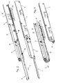
Fig. 1 eine Schrägsicht einer Ausziehführung gemäß der Erfindung im eingeschobenen Zustand; -
Fig. 2 die Ausziehführung vonFig. 1 im ausgezogenen Zustand; -
Fig. 3 eine stirnseitige Ansicht der Ausziehführung; -
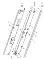
Fig. 4, 5 und 6 Schrägsichten der Korpusschiene, Mittelschiene und Ausziehschiene; -
Fig. 7, 8 und 9 Schrägsichten der Korpusschiene, Mittelschiene und Ausziehschiene von der anderen Seite; -
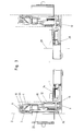
Fig. 10 und 11 vergrößerte Abschnitte eines hinteren Teils der Ausziehführung beim Einfahren, in zwei unterschiedlichen Stellungen; -
Fig. 12 und 13 Schrägsichten der Einzugseinheit in der Anfangsstellung (Fig. 12 ) und Endstellung (Fig. 13 ) des Kippschiebers; -
Fig. 14 die Einzugseinheit ohne ihre Montageplatte in einer Schrägsicht von der gegenüberliegenden Seite, in der Endstellung des Kippschiebers; -
Fig. 15 eine Schrägsicht analogFig. 14 , das Führungsteil der Einzugseinheit entfernt; -
Fig. 16 eine Schrägsicht analogFig. 14 , aber in der Anfangsstellung des Kippschiebers; -
Fig. 17 eine Schrägsicht analogFig. 15 , aber in der Anfangsstellung des Kippschiebers. Die Figuren weisen unterschiedliche Maßstäbe auf.
-
Fig. 1 an oblique view of a pull-out according to the invention in the inserted state; -
Fig. 2 the pull-out guide ofFig. 1 in the extended state; -
Fig. 3 an end view of the pull-out; -
4, 5 and 6 Oblique views of the carcass rail, center rail and pull-out rail; -
FIGS. 7, 8 and 9 Oblique views of the carcass rail, center rail and pull-out rail from the other side; -
10 and 11 enlarged sections of a rear part of the extension guide during retraction, in two different positions; -
FIGS. 12 and 13 Oblique views of the feeder unit in the initial position (Fig. 12 ) and end position (Fig. 13 ) of the tilting slide; -
Fig. 14 the feeder unit without its mounting plate in an oblique view from the opposite side, in the end position of the tilting slide; -
Fig. 15 an oblique view analogFig. 14 removing the guide part of the feeder unit; -
Fig. 16 an oblique view analogFig. 14 but in the initial position of the tilt slide; -
Fig. 17 an oblique view analogFig. 15 but in the initial position of the tilt slide. The figures have different scales.
In den
Die Korpusschiene 4 besitzt einen vertikalen Basissteg 7, mit dem sie in befestigtem Zustand am Möbelkorpus 2 anliegt, und mit dem Basissteg 7 im Bereich seines oberen und unteren Randes verbundene obere und untere Horizontalflansche 8, 9. Diese können mit dem Basissteg 7 direkt oder wie aus
Die Ausziehschiene 6 besitzt einen vertikalen Basissteg 12, einen mit dem Basissteg 12 im Bereich seines oberen Randes verbundenen Horizontalflansch 13 und einen im Bereich des unteren Randes des Basisstegs 12 mit diesem verbundenen Horizontalflansch 14, der auf der anderen Seite wie der Horizontalflansch 13 vom Basissteg 12 absteht. Das ausziehbare Möbelteil 1 wird im gezeigten Ausführungsbeispiel vom Horizontalflansch 14 getragen. Der Horizontalflansch 14 könnte auch entfallen und die Befestigung des ausziehbaren Möbelteils 1 könnte am vertikalen Basissteg 12 erfolgen.The pull-out
Die Laufrollen 17-21 zur gegenseitigen verschiebbaren Führung der Schienen 4, 5, 6 sind im gezeigten Ausführungsbeispiel alle an der Mittelschiene 5 drehbar gelagert. Hierbei sind an der Mittelschiene 5 im Bereich ihres vorderen Endes 15 eine vordere Laufrolle 17, im Bereich ihres hinteren Endes 16 eine hintere Laufrolle 18 und in ihrem mittleren Bereich eine mittlere Laufrolle 19 und eine Differentialrolle 20 drehbar gelagert.The rollers 17-21 for mutually displaceable guidance of the
Die vordere Laufrolle 17 wirkt mit einer Laufbahn an der Unterseite des Horizontalflansches 13 der Ausziehschiene 6 zusammen und stützt die Ausziehschiene 6 im ausgezogenen Zustand der Schienen gegen ein Abkippen nach unten ab. Die hintere Laufrolle 18 wirkt mit einer Laufbahn an der Unterseite des oberen Horizontalflansches 8 der Korpusschiene 4 zusammen und stützt das hintere Ende 16 der Mittelschiene 5 im ausgezogenen Zustand der Ausziehführung gegen eine Verschwenkung nach oben ab. Die mittlere Laufrolle 19 wirkt mit einer Laufbahn an der Oberseite des Horizontalflansches 13 der Ausziehschiene 6 zusammen und bildet im ausgezogenen Zustand der Schienen ein Gegenlager für die Ausziehschiene 6 (gegen eine Verschwenkung der Ausziehschiene nach oben).The
Die Differentialrolle 20 wirkt sowohl mit einer Laufbahn an der Oberseite des unteren Horizontalflansches 9 der Korpusschiene 4 als auch mit der Laufbahn an der Unterseite des Horizontalflansches 13 der Ausziehschiene 6 zusammen und bewirkt den differentiellen Lauf der Mittelschiene 5. Bei der Differentialrolle 20 handelt es sich um eine lastübertragende Rolle, über welche eine Last von der Ausziehschiene 6 direkt auf die Korpusschiene 4 übertragen wird. Die Differentialrolle 20 ist günstigerweise mit Spiel gegenüber ihrer Drehachse gelagert, wie dies bekannt und üblich ist. Auch eine achslose Lagerung der Differentialrolle 20 an der Mittelschiene 5 oder eine Lagerung an einer Achse, die gegenüber der Mittelschiene 5 ein Spiel in vertikaler Richtung aufweist, ist denkbar und möglich.The
Vorzugsweise ist weiters an der Mittelschiene 5 eine Hilfsrolle 21 mit Spiel gegenüber ihrer Drehachse gelagert, und zwar in einem zwischen der Differentialrolle 20 und dem hinteren Ende 16 der Mittelschiene 5 liegenden Bereich der Längserstreckung der Mittelschiene 5. Diese Hilfsrolle 21 dient zur Abstützung gegen ein Abkippen nach unten des hinteren Endes der Ausziehschiene 6 im eingefahrenen bzw. nur wenig ausgezogenen Zustand der Ausziehführung.Preferably, an
Grundsätzlich könnten auch weitere Hilfsrollen vorgesehen sein. Denkbar und möglich wäre es prinzipiell auch, anstelle der gezeigten Hilfsrolle 21 mindestens eine Hilfsrolle im Bereich zwischen der mittleren Laufrolle 19 und der vorderen Laufrolle 17 an der Mittelschiene 5 drehbar zu lagern, die mit der Laufbahn an der Oberseite des Horizontalflansches 13 der Ausziehschiene 6 zusammenwirkt.In principle, other auxiliary roles could be provided. It is conceivable and possible in principle, instead of the
Zusätzlich zur Differentialrolle 20 könnte auch die mittlere Laufrolle 19 mit Spiel gegenüber ihrer Achse gelagert sein. In diesem Fall könnte die Differentialrolle 20 auch spielfrei auf ihrer Achse gelagert sein, wobei zwischen den Laufbahnen und den Laufrollen dann nur ein kleines Spiel vorhanden sein sollte, um beim Lastwechsel beim Ausziehen eine kippfreie Bewegung der Führung zu erreichen.In addition to the
Im gezeigten Ausführungsbeispiel weist die Mittelschiene zwei über eine Abkröpfung miteinander verbundene vertikale Abschnitte 22, 23 auf, wodurch eine stabile Ausbildung erreicht wird. Auch ein durchgehender vertikaler Steg könnte vorgesehen sein. Im Bereich ihres unteren Endes weist die Mittelschiene einen seitlich abstehenden Steg 24 auf, an dem im gezeigten Ausführungsbeispiel Anschläge 38, 39 angeordnet sind, die von am Steg 24 angebrachten Teilen gebildet werden. Denkbar und möglich wäre es auch solche Anschläge direkt an einem vertikalen Abschnitt bzw. Steg der Mittelschiene 5 zu befestigen.In the exemplary embodiment shown, the middle rail has two
An der Korpusschiene 4 ist eine Einzugseinheit 25 befestigt. Die Einzugseinheit 25 besitzt einen Kippschieber 26, der an einem Schlitten 27 um eine Achse 28 verschwenkbar gelagert ist. Der Schlitten 27 ist von einem Führungsteil 29 verschiebbar gelagert und von einer Einziehfeder 33 beaufschlagt. Günstigerweise kann der Kippschieber 26 mit dem Schlitten 27 durch Einclipsen eines Schwenkkopfes 30 des Schlittens 27 in eine diesen aufnehmende Ausnehmung des Kippschiebers 26 verbunden werden, wodurch sich eine einfache Montage ergibt. Auch andere verschwenkbare Verbindungen des Kippschiebers 26 mit dem Schlitten 27 sind denkbar und möglich.On the
Der Kippschieber 26 besitzt beidseitig abstehende Führungszapfen 31, die in beidseitig des Kippschiebers 26 angeordneten Kulissen 32 des Führungsteils 29 eingreifen. Die Kulissen 32 besitzen einen in die Ausziehrichtung 3 sich erstreckenden Abschnitt und im Bereich ihres vorderen Endes einen abgekrümmten Abschnitt. Dadurch ist die Schwenkstellung des Kippschiebers 26 in jeder Verschiebestellung des Schlittens 27 eindeutig definiert.The tilting
Die Führung des Schlittens im Führungsteil 29 kann wie dargestellt über in den geraden Abschnitt der Kulissen 32 eingreifende beidseitig abstehende Zapfen 44, 45 des Schlittens 27 erfolgen. Auch andere Arten von Führungen des Schlittens 27 im Führungsteil 29 sind denkbar und möglich.The guide of the carriage in the
Der Kippschieber 26 wirkt mit einem Mitnehmer 34 der Ausziehschiene zusammen. Der Mitnehmer 34 wird von einem im Bereich des unteren Endes der Ausziehschiene angeordneten Vorsprung gebildet. Im gezeigten Ausführungsbeispiel ist der Vorsprung am unteren Horizontalflansch 14 der Ausziehschiene 6 angebracht. Wenn die Ausziehschiene 6 ohne einen unteren Horizontalflansch 14 ausgebildet ist, so könnte der Mitnehmer 34 am unteren Ende des vertikalen Basisstegs 12 befestigt sein.The tilting
Im vollständig eingefahrenen Zustand der Ausziehführung befindet sich der Kippschieber 26 in seiner Anfangsstellung (vgl.
Beim Einschieben der Ausziehschiene 6 läuft der Mitnehmer 34 an den sich in seiner verschwenkten Einstellung befindenden Kippschieber an und löst diesen aus seiner verkippten Endstellung, wobei er sich um seine Achse 28 zurückschwenkt, sodass die Selbsthemmung aufgehoben wird und der Mitnehmer 34 so in Eingriff der Vertiefung 35 gelangt, dass er beidseitig (in und entgegen der Ausziehrichtung) in der Vertiefung 35 gehalten ist. In der Folge zieht die Einziehfeder 33 den Kippschieber 26 bis in seine Anfangsstellung zurück, wobei er den Mitnehmer 34 und somit auch die Ausziehschiene 6 mitnimmt.When inserting the pull-out
Grundsätzlich könnten auch nur ein einzelner Führungszapfen 31 des Kippschiebers 26 und eine Kulisse 32 vorhanden sein. Der Führungszapfen 31 und die Kulisse 32 könnten grundsätzlich auch ganz entfallen, wie dies beispielsweise aus dem in der Beschreibungseinleitung zu Einzugsmechaniken genannten Stand der Technik bekannt ist. Andererseits könnte auch der Schlitten 27 entfallen und der Kippschieber 26 beispielsweise mittels zwei Führungszapfen in einer Kulisse bzw. mittels jeweils zwei Führungszapfen in gegenüberliegenden Kulissen verschiebbar gelagert sein, wie dies ebenfalls aus dem in der Beschreibungseinleitung genannten Stand der Technik bekannt ist.In principle, only a
Der Kippschieber 26 wirkt mit einem Einschubdämpfer 36 zusammen, um die Einschubbewegung der Ausziehführung in ihrem letzten Abschnitt, in welchem der Kippschieber 26 zwischen seiner verkippten Endstellung und seiner Anfangstellung verschoben wird, zu dämpfen. Dieser Einschubdämpfer 36 ist im gezeigten Ausführungsbeispiel mit dem Schlitten 27 verbunden. Der Einschubdämpfer 36 könnte auch direkt am Kippschieber 26 angreifen. Im gezeigten Ausführungsbeispiel ist der Einschubdämpfer 36 in Form einer Kolben-Zylinder-Einheit ausgebildet, wobei die Kolbenstange am Schlitten 27 befestigt ist und der Zylinder stationär zum Führungsteil 29 gehalten ist. Auch die umgekehrte Anordnung (mit stationärer Kolbenstange) ist denkbar und möglich. Auch andere Ausbildungen von Einschubdämpfern 36 sind denkbar und möglich.The tilting
Die mindestens eine Einziehfeder 33 könnte auch direkt am Kippschieber 26 angreifen.The at least one pulling-in
Die Einzugseinheit 25 ist im gezeigten Ausführungsbeispiel mittels einer Montageplatte 46, an der das Führungsteil 29 der Einzugseinheit 25 gehalten ist, am unteren Horizontalflansch 9 der Korpusschiene 4 befestigt. Auch andere Befestigungen an der Korpusschiene, beispielsweise am vertikalen Basissteg 7 sind denkbar und möglich.The
Die Einzugseinheit 25 weist weiters einen am Schlitten 27 angeordneten Anschlag 37 auf. Dieser ist für ein Zusammenwirken mit einem an der Mittelschiene angeordneten Anschlag 38 vorgesehen. Wenn die Ausziehführung ausgehend von ihrem vollständig ausgezogenen Zustand eingeschoben wird, so legt die Ausziehschiene 6 im Normalbetrieb jeweils die doppelte Wegstrecke der Mittelschiene 5 zurück und der Mitnehmer 34 gelangt in Eingriff mit dem Kippschieber 26, bevor der Anschlag 38 der Mittelschiene 5 an den Anschlag 37 anläuft. Wenn nunmehr ein Betriebszustand auftritt, in welchem die Ausziehschiene 6 gegenüber ihrer Stellung im Normalbetrieb zurückbleibt (d.h. in Ausziehrichtung 3 gegenüber ihrer Stellung im Normalbetrieb verschoben ist), so kommt es zu einem Anlaufen des Anschlags 38 der Mittelschiene 5 an den Anschlag 37, bevor der Mitnehmer 34 in Eingriff mit dem Kippschieber 26 gelangt. Dies ist in
Der Anschlag 37 der Einzugseinheit 25 kann auch an einem anderen mit dem Kippschieber 26 bei dessen Verschiebung gegenüber der Korpusschiene 4 mitbewegten Teil angeordnet sein, beispielsweise am Kippschieber 26 selbst. Der Anschlag 37 und/oder der Anschlag 38 kann federnd ausgebildet sein, um ein weiches gegenseitiges Anfahren der Anschläge 37, 38 zu bewirken. Hierbei können die Anschläge 37, 38 in Längsrichtung der Ausziehführung (d.h. bezogen auf die Ausziehrichtung 3) geringfügig verschiebbar gegenüber dem Kippschieber 26 bzw. der Mittelschiene 5 sein.The
Im gezeigten Ausführungsbeispiel sind die Anordnung des Anschlags 38 an der Mittelschiene 5 und die Anordnung des Mitnehmers 34 an der Ausziehschiene 6 so aufeinander abgestimmt, dass im vollständig eingeschobenen Zustand der Ausziehführung der Mitnehmer 34 an den Anschlag 38 der Mittelschiene 5 anfährt und eine weitere Verschiebung der Ausziehschiene 6 entgegen der Ausziehrichtung 3 gegenüber der Mittelschiene 5 blockiert.In the exemplary embodiment shown, the arrangement of the
Im vollständig ausgezogenen Zustand der Ausziehschiene 6 läuft der Mitnehmer 34 an einen Anschlag 39 der Mittelschiene 5 an, wodurch eine weitere Verschiebung der Ausziehschiene 6 gegenüber der Mittelschiene 5 in die Ausziehrichtung 3 blockiert wird (vgl.
Zur Begrenzung der Verschiebung der Mittelschiene 5 gegenüber der Korpusschiene 4 in und entgegen der Ausziehrichtung 3 dienen zusammenwirkende Anschläge 40, 41; 42, 43 der Korpusschiene 4 und Mittelschiene 5 (vgl.
- 11
- ausziehbares Möbelteilextendable furniture part
- 22
- Möbelkorpusfurniture body
- 33
- Ausziehrichtungpull-out
- 44
- Korpusschienecabinet member
- 55
- Mittelschienemiddle rail
- 66
- Ausziehschienepull-out
- 77
- vertikaler Basisstegvertical base bar
- 88th
- Horizontalflanschhorizontal flange
- 99
- Horizontalflanschhorizontal flange
- 1010
- Umbördelungbeading
- 1111
- Umbördelungbeading
- 1212
- vertikaler Basisstegvertical base bar
- 1313
- Horizontalflanschhorizontal flange
- 1414
- Horizontalflanschhorizontal flange
- 1515
- vorderes Endefront end
- 1616
- hinteres Enderear end
- 1717
- vordere Laufrollefront caster
- 1818
- hintere Laufrollerear caster
- 1919
- mittlere Laufrollemiddle roller
- 2020
- Differentialrolledifferential roller
- 2121
- Hilfsrolleauxiliary role
- 2222
- vertikaler Abschnittvertical section
- 2323
- vertikaler Abschnittvertical section
- 2424
- Stegweb
- 2525
- Einzugseinheitfeed unit
- 2626
- Kippschiebertilt slide
- 2727
- Schlittencarriage
- 2828
- Achseaxis
- 2929
- Führungsteilguide part
- 3030
- Schwenkkopfswivel head
- 3131
- Führungszapfenspigot
- 3232
- Kulissescenery
- 3333
- Einziehfederretraction
- 3434
- Mitnehmertakeaway
- 3535
- Vertiefungdeepening
- 3636
- Einschubdämpferslide-in attenuator
- 3737
- Anschlagattack
- 3838
- Anschlagattack
- 3939
- Anschlagattack
- 4040
- Anschlagattack
- 4141
- Anschlagattack
- 4242
- Anschlagattack
- 4343
- Anschlagattack
- 4444
- Zapfenspigot
- 4545
- Zapfenspigot
- 4646
- Montageplattemounting plate
Claims (11)
Applications Claiming Priority (1)
| Application Number | Priority Date | Filing Date | Title |
|---|---|---|---|
| AT0211707A AT506062B1 (en) | 2007-12-27 | 2007-12-27 | ROLLS-pull-out |
Publications (2)
| Publication Number | Publication Date |
|---|---|
| EP2074909A1 true EP2074909A1 (en) | 2009-07-01 |
| EP2074909B1 EP2074909B1 (en) | 2010-06-23 |
Family
ID=40328730
Family Applications (1)
| Application Number | Title | Priority Date | Filing Date |
|---|---|---|---|
| EP08020594A Active EP2074909B1 (en) | 2007-12-27 | 2008-11-27 | Extending roller guide |
Country Status (3)
| Country | Link |
|---|---|
| EP (1) | EP2074909B1 (en) |
| AT (2) | AT506062B1 (en) |
| DE (1) | DE502008000826D1 (en) |
Cited By (7)
| Publication number | Priority date | Publication date | Assignee | Title |
|---|---|---|---|---|
| EP2428136A1 (en) | 2010-09-10 | 2012-03-14 | Fulterer Gesellschaft m.b.H. | Drawer slide |
| AT516509B1 (en) * | 2015-03-27 | 2016-06-15 | Fulterer Gmbh | Pull-out for pull out of a furniture body and in this again retractable furniture parts |
| CN105815950A (en) * | 2016-05-09 | 2016-08-03 | 无锡海达尔精密滑轨股份有限公司 | Self-closing device of sliding rail component |
| CN106774718A (en) * | 2016-12-22 | 2017-05-31 | 广东星徽精密制造股份有限公司 | A kind of server with can sequential movements slide rail |
| CN109527848A (en) * | 2018-12-27 | 2019-03-29 | 江苏星徽精密科技有限公司 | A kind of drawer sliding rail with double self-locking functions |
| CN111631529A (en) * | 2020-04-21 | 2020-09-08 | 北京花都家美办公家具有限公司 | File cabinet with self-locking function |
| AT520673A3 (en) * | 2017-12-04 | 2021-07-15 | Grass Gmbh | Movement mechanism for a guide system |
Families Citing this family (3)
| Publication number | Priority date | Publication date | Assignee | Title |
|---|---|---|---|---|
| AT14099U1 (en) | 2014-01-14 | 2015-04-15 | Fulterer Gmbh | Arrangement with at least one rotatably mounted on a pivot pin roller |
| AT516222B1 (en) | 2014-08-25 | 2018-01-15 | Fulterer Gmbh | pull-out |
| CN108991782B (en) * | 2018-08-25 | 2023-09-29 | 广东星徽精密制造股份有限公司 | Buffer slide rail for driving friction silencing mechanism |
Citations (10)
| Publication number | Priority date | Publication date | Assignee | Title |
|---|---|---|---|---|
| FR2311514A1 (en) * | 1975-05-23 | 1976-12-17 | Blum Gmbh Julius | DRAWER OPENING GUIDE |
| DE3925815A1 (en) * | 1988-08-29 | 1990-03-01 | Fulterer Gmbh | Drawer pull=out system with three telescopic rails - has middle rail with top and bottom bridging piece, and horizontal flange joining them |
| AT391603B (en) | 1989-03-09 | 1990-11-12 | Fulterer Gmbh | DRAWER DRAWER DIFFERENTIAL DESIGN |
| AT393948B (en) | 1989-04-03 | 1992-01-10 | Blum Gmbh Julius | LOCKING DEVICE FOR DRAWERS |
| EP0631745A1 (en) | 1993-06-23 | 1995-01-04 | Julius Blum Gesellschaft m.b.H. | Closing device for drawers |
| AT401334B (en) | 1990-07-31 | 1996-08-26 | Blum Gmbh Julius | LOCKING DEVICE FOR DRAWERS |
| EP1120066A2 (en) | 2000-01-14 | 2001-08-01 | Julius Blum Gesellschaft m.b.H. | Closure and/or retraction device for moving furniture parts |
| EP1532892A1 (en) | 2003-11-21 | 2005-05-25 | Fulterer Gesellschaft m.b.H. | Automatic retraction device |
| EP1561398A1 (en) | 2004-02-07 | 2005-08-10 | Schock Metallwerk GmbH | Extensible guide for drawer |
| US20070241651A1 (en) * | 2006-04-17 | 2007-10-18 | Burgess Thomas E Iii | Drawer slide with releasable latch |
-
2007
- 2007-12-27 AT AT0211707A patent/AT506062B1/en not_active IP Right Cessation
-
2008
- 2008-11-27 EP EP08020594A patent/EP2074909B1/en active Active
- 2008-11-27 AT AT08020594T patent/ATE471675T1/en active
- 2008-11-27 DE DE502008000826T patent/DE502008000826D1/en active Active
Patent Citations (11)
| Publication number | Priority date | Publication date | Assignee | Title |
|---|---|---|---|---|
| FR2311514A1 (en) * | 1975-05-23 | 1976-12-17 | Blum Gmbh Julius | DRAWER OPENING GUIDE |
| DE3925815A1 (en) * | 1988-08-29 | 1990-03-01 | Fulterer Gmbh | Drawer pull=out system with three telescopic rails - has middle rail with top and bottom bridging piece, and horizontal flange joining them |
| AT392883B (en) | 1988-08-29 | 1991-06-25 | Fulterer Gmbh | DRAWER EXTENSION |
| AT391603B (en) | 1989-03-09 | 1990-11-12 | Fulterer Gmbh | DRAWER DRAWER DIFFERENTIAL DESIGN |
| AT393948B (en) | 1989-04-03 | 1992-01-10 | Blum Gmbh Julius | LOCKING DEVICE FOR DRAWERS |
| AT401334B (en) | 1990-07-31 | 1996-08-26 | Blum Gmbh Julius | LOCKING DEVICE FOR DRAWERS |
| EP0631745A1 (en) | 1993-06-23 | 1995-01-04 | Julius Blum Gesellschaft m.b.H. | Closing device for drawers |
| EP1120066A2 (en) | 2000-01-14 | 2001-08-01 | Julius Blum Gesellschaft m.b.H. | Closure and/or retraction device for moving furniture parts |
| EP1532892A1 (en) | 2003-11-21 | 2005-05-25 | Fulterer Gesellschaft m.b.H. | Automatic retraction device |
| EP1561398A1 (en) | 2004-02-07 | 2005-08-10 | Schock Metallwerk GmbH | Extensible guide for drawer |
| US20070241651A1 (en) * | 2006-04-17 | 2007-10-18 | Burgess Thomas E Iii | Drawer slide with releasable latch |
Cited By (11)
| Publication number | Priority date | Publication date | Assignee | Title |
|---|---|---|---|---|
| EP2428136A1 (en) | 2010-09-10 | 2012-03-14 | Fulterer Gesellschaft m.b.H. | Drawer slide |
| AT510258B1 (en) * | 2010-09-10 | 2012-03-15 | Fulterer Gmbh | pull-out |
| AT516509B1 (en) * | 2015-03-27 | 2016-06-15 | Fulterer Gmbh | Pull-out for pull out of a furniture body and in this again retractable furniture parts |
| AT516509A4 (en) * | 2015-03-27 | 2016-06-15 | Fulterer Gmbh | Pull-out for pull out of a furniture body and in this again retractable furniture parts |
| CN105815950A (en) * | 2016-05-09 | 2016-08-03 | 无锡海达尔精密滑轨股份有限公司 | Self-closing device of sliding rail component |
| CN105815950B (en) * | 2016-05-09 | 2018-06-05 | 无锡海达尔精密滑轨股份有限公司 | The self-closing device of slide assemblies |
| CN106774718A (en) * | 2016-12-22 | 2017-05-31 | 广东星徽精密制造股份有限公司 | A kind of server with can sequential movements slide rail |
| AT520673A3 (en) * | 2017-12-04 | 2021-07-15 | Grass Gmbh | Movement mechanism for a guide system |
| CN109527848A (en) * | 2018-12-27 | 2019-03-29 | 江苏星徽精密科技有限公司 | A kind of drawer sliding rail with double self-locking functions |
| CN109527848B (en) * | 2018-12-27 | 2023-09-19 | 江苏玖星精密科技集团有限公司 | Drawer slide rail with double self-locking function |
| CN111631529A (en) * | 2020-04-21 | 2020-09-08 | 北京花都家美办公家具有限公司 | File cabinet with self-locking function |
Also Published As
| Publication number | Publication date |
|---|---|
| AT506062A4 (en) | 2009-06-15 |
| ATE471675T1 (en) | 2010-07-15 |
| AT506062B1 (en) | 2009-06-15 |
| EP2074909B1 (en) | 2010-06-23 |
| DE502008000826D1 (en) | 2010-08-05 |
Similar Documents
| Publication | Publication Date | Title |
|---|---|---|
| EP2074909B1 (en) | Extending roller guide | |
| EP2129260B1 (en) | Roller differential extension guide | |
| EP2916688B1 (en) | Drawer pull out guide | |
| AT513608B1 (en) | Pull-out guide for a piece of furniture which can be pulled out of a furniture carcass | |
| EP2144530B1 (en) | Telescopic guide rail | |
| EP1795088A1 (en) | Differential slide for extensible furniture parts | |
| EP2992781B1 (en) | Pull-out guide | |
| EP2464258B1 (en) | Pull-in or pull-out device for moving a movable furniture part | |
| EP0957714B1 (en) | Flush-mounted extraction guide for drawers etc. | |
| WO2019033136A1 (en) | Drawer pull-out guide | |
| EP2046164B1 (en) | Pull-out guide for guiding furniture parts | |
| EP3498131B1 (en) | Removal guide | |
| AT521511B1 (en) | Selbsteinziehvorrichtung | |
| EP1384420B1 (en) | Damped self closing mechanism | |
| WO2017070722A1 (en) | Drawer pull-out guide | |
| EP2716182B1 (en) | Extension guide for a pull-out furniture part extendible from a furniture body | |
| EP2428136B1 (en) | Drawer slide | |
| EP3142879B1 (en) | Arrangement with a cover for a vehicle roof | |
| EP1452113B1 (en) | Slide device for extensible furniture parts |
Legal Events
| Date | Code | Title | Description |
|---|---|---|---|
| PUAI | Public reference made under article 153(3) epc to a published international application that has entered the european phase |
Free format text: ORIGINAL CODE: 0009012 |
|
| AK | Designated contracting states |
Kind code of ref document: A1 Designated state(s): AT BE BG CH CY CZ DE DK EE ES FI FR GB GR HR HU IE IS IT LI LT LU LV MC MT NL NO PL PT RO SE SI SK TR |
|
| AX | Request for extension of the european patent |
Extension state: AL BA MK RS |
|
| GRAP | Despatch of communication of intention to grant a patent |
Free format text: ORIGINAL CODE: EPIDOSNIGR1 |
|
| 17P | Request for examination filed |
Effective date: 20090831 |
|
| GRAS | Grant fee paid |
Free format text: ORIGINAL CODE: EPIDOSNIGR3 |
|
| AKX | Designation fees paid |
Designated state(s): AT CH DE GB IT LI NL |
|
| GRAA | (expected) grant |
Free format text: ORIGINAL CODE: 0009210 |
|
| AK | Designated contracting states |
Kind code of ref document: B1 Designated state(s): AT CH DE GB IT LI NL |
|
| REG | Reference to a national code |
Ref country code: CH Ref legal event code: EP |
|
| REG | Reference to a national code |
Ref country code: CH Ref legal event code: NV Representative=s name: LUCHS & PARTNER AG PATENTANWAELTE |
|
| REF | Corresponds to: |
Ref document number: 502008000826 Country of ref document: DE Date of ref document: 20100805 Kind code of ref document: P |
|
| REG | Reference to a national code |
Ref country code: NL Ref legal event code: T3 |
|
| PLBE | No opposition filed within time limit |
Free format text: ORIGINAL CODE: 0009261 |
|
| STAA | Information on the status of an ep patent application or granted ep patent |
Free format text: STATUS: NO OPPOSITION FILED WITHIN TIME LIMIT |
|
| 26N | No opposition filed |
Effective date: 20110324 |
|
| REG | Reference to a national code |
Ref country code: DE Ref legal event code: R097 Ref document number: 502008000826 Country of ref document: DE Effective date: 20110323 |
|
| REG | Reference to a national code |
Ref country code: DE Ref legal event code: R079 Ref document number: 502008000826 Country of ref document: DE Free format text: PREVIOUS MAIN CLASS: A47B0088040000 Ipc: A47B0088400000 |
|
| PGFP | Annual fee paid to national office [announced via postgrant information from national office to epo] |
Ref country code: NL Payment date: 20191127 Year of fee payment: 12 |
|
| PGFP | Annual fee paid to national office [announced via postgrant information from national office to epo] |
Ref country code: GB Payment date: 20191128 Year of fee payment: 12 |
|
| REG | Reference to a national code |
Ref country code: NL Ref legal event code: MM Effective date: 20201201 |
|
| GBPC | Gb: european patent ceased through non-payment of renewal fee |
Effective date: 20201127 |
|
| PG25 | Lapsed in a contracting state [announced via postgrant information from national office to epo] |
Ref country code: NL Free format text: LAPSE BECAUSE OF NON-PAYMENT OF DUE FEES Effective date: 20201201 |
|
| PG25 | Lapsed in a contracting state [announced via postgrant information from national office to epo] |
Ref country code: GB Free format text: LAPSE BECAUSE OF NON-PAYMENT OF DUE FEES Effective date: 20201127 |
|
| REG | Reference to a national code |
Ref country code: DE Ref legal event code: R082 Ref document number: 502008000826 Country of ref document: DE Representative=s name: VKK PATENTANWAELTE PARTG MBB, DE |
|
| P01 | Opt-out of the competence of the unified patent court (upc) registered |
Effective date: 20230514 |
|
| PGFP | Annual fee paid to national office [announced via postgrant information from national office to epo] |
Ref country code: IT Payment date: 20231130 Year of fee payment: 16 Ref country code: DE Payment date: 20231120 Year of fee payment: 16 Ref country code: CH Payment date: 20231202 Year of fee payment: 16 Ref country code: AT Payment date: 20231117 Year of fee payment: 16 |