EP2072872A1 - Montagewinkel - Google Patents
Montagewinkel Download PDFInfo
- Publication number
- EP2072872A1 EP2072872A1 EP08105897A EP08105897A EP2072872A1 EP 2072872 A1 EP2072872 A1 EP 2072872A1 EP 08105897 A EP08105897 A EP 08105897A EP 08105897 A EP08105897 A EP 08105897A EP 2072872 A1 EP2072872 A1 EP 2072872A1
- Authority
- EP
- European Patent Office
- Prior art keywords
- sound
- mounting bracket
- slot
- leg
- housing parts
- Prior art date
- Legal status (The legal status is an assumption and is not a legal conclusion. Google has not performed a legal analysis and makes no representation as to the accuracy of the status listed.)
- Granted
Links
Images

Classifications
-
- F—MECHANICAL ENGINEERING; LIGHTING; HEATING; WEAPONS; BLASTING
- F16—ENGINEERING ELEMENTS AND UNITS; GENERAL MEASURES FOR PRODUCING AND MAINTAINING EFFECTIVE FUNCTIONING OF MACHINES OR INSTALLATIONS; THERMAL INSULATION IN GENERAL
- F16L—PIPES; JOINTS OR FITTINGS FOR PIPES; SUPPORTS FOR PIPES, CABLES OR PROTECTIVE TUBING; MEANS FOR THERMAL INSULATION IN GENERAL
- F16L3/00—Supports for pipes, cables or protective tubing, e.g. hangers, holders, clamps, cleats, clips, brackets
- F16L3/006—Supports for pipes, cables or protective tubing, e.g. hangers, holders, clamps, cleats, clips, brackets for pipes with a rectangular cross-section
-
- F—MECHANICAL ENGINEERING; LIGHTING; HEATING; WEAPONS; BLASTING
- F16—ENGINEERING ELEMENTS AND UNITS; GENERAL MEASURES FOR PRODUCING AND MAINTAINING EFFECTIVE FUNCTIONING OF MACHINES OR INSTALLATIONS; THERMAL INSULATION IN GENERAL
- F16L—PIPES; JOINTS OR FITTINGS FOR PIPES; SUPPORTS FOR PIPES, CABLES OR PROTECTIVE TUBING; MEANS FOR THERMAL INSULATION IN GENERAL
- F16L55/00—Devices or appurtenances for use in, or in connection with, pipes or pipe systems
- F16L55/02—Energy absorbers; Noise absorbers
- F16L55/033—Noise absorbers
- F16L55/035—Noise absorbers in the form of specially adapted hangers or supports
-
- F—MECHANICAL ENGINEERING; LIGHTING; HEATING; WEAPONS; BLASTING
- F24—HEATING; RANGES; VENTILATING
- F24F—AIR-CONDITIONING; AIR-HUMIDIFICATION; VENTILATION; USE OF AIR CURRENTS FOR SCREENING
- F24F13/00—Details common to, or for air-conditioning, air-humidification, ventilation or use of air currents for screening
- F24F13/02—Ducting arrangements
- F24F13/0254—Ducting arrangements characterised by their mounting means, e.g. supports
Definitions
- the invention relates to a mounting bracket for fastening a channel to a construction element with an angle element, which has a first leg for attachment to the channel and at least one second leg with a first opening for a fastening element for fixing the mounting bracket on the structural element, with a first housing part, which has a second through-opening for the fastening element, and with a second housing part, which has a third through-opening for the fastening element, wherein the housing parts at least partially surrounds the second leg on two opposite sides, and with a fourth through opening for the fastening element having sound-insulating element that partially surrounds the second leg and decoupled from the housing parts.
- ventilation ducts made of sheet metal with mounting angles indirectly, z. B. mounting rails, or attached directly to construction elements such as a building, such. B. on ceilings or on walls.
- construction elements such as a building, such. B. on ceilings or on walls.
- sound-insulating elements are provided at these mounting angles, which allow a decoupling of the attachment.
- a generic mounting bracket with a Z-shaped angle element which has a passage opening for a fastening element on a second leg, said second leg partially circumferentially from a through opening for the fastener having sound-absorbing Element is surrounded.
- a first and a second disc-shaped housing part are respectively provided, which surround the second leg in regions on two opposite sides and each having a passage opening for the fastening element. The sound-absorbing element decouples the second leg from the housing parts.
- a disadvantage of the known solution is that the mounting bracket is only partially adjustable.
- the attachment points on the ground often agree, z. B. due to inaccurate positioning or in concrete substrates due to reinforcement hits, with the actually required positions do not match, so that they are slightly shifted from these.
- This requires a certain adjustability of the created attachment even in the assembled state of the mounting bracket, which is given only conditionally in the region of the diameter difference between the fastener and the passage opening in the second leg in the known mounting bracket.
- the object of the invention is to provide a mounting bracket for mounting a channel to a substrate, which is adjustable in the assembled state and at the same time easy to manufacture.
- the lead-through openings in the at least one second limb, the housing parts and in the sound-insulating element are elongated holes, wherein the slot in the at least one second limb lies in complete overlap with the oblong holes in the housing parts and the oblong hole in the sound-insulating element.
- the slots in said parts of the mounting bracket are aligned or arranged coaxially with each other with respect to a common plane of passage for the fastener and its longitudinal axes. With the slots arranged one above the other, the displaceability of a construction angle directly or indirectly arranged mounting bracket is given and clearly visible to the user. In this case, the mounting bracket is easy to produce, since only a few parts must be joined together, which may have a large tolerance range. This ensures not only the advantageous sound decoupling economic production and installation of the mounting bracket.
- the angle element is for example L- or Z-shaped, wherein advantageously the first leg of the angle element with a plurality of holes z. B. is provided for mounting screws for mounting the mounting bracket to a channel.
- the angle element is advantageously a stamped / bent part made of metal.
- the sound-absorbing element is advantageously made of an elastic plastic z. B. manufactured in an extrusion process.
- the sound-absorbing element comprises, for example, two sub-elements which are provided on both sides of the at least one second leg between the housing parts.
- the sound-insulating element is tubular and is pushed over the one end of the mounting bracket on the at least one second leg of the angle element until its formed as a slot fourth through opening comes to lie above the formed as a slot first passage opening in at least one second leg.
- this is as two connected via a film joint flat elements z. B. formed in an extrusion process, which is folded for mounting on at least one second leg of the angle element around it.
- the passage openings for the fastening element in each part or of the sound-insulating element form the fourth through-opening for the fastening element in the folded-up state of the sound-insulating element. To form the slots in the sound-absorbing element, these are advantageously punched out of this.
- the housing parts are connected to one another via a hinge and are folded around the already previously arranged on the at least one second leg of the mounting bracket sound-insulating element around and connected to each other for mounting.
- the fastener is for example a threaded rod, directly on the construction element or indirectly z. B. is arranged via a rail nut on a mounting rail. The threaded rod is guided with one end through the superimposed through-openings, wherein the mounting bracket is set via securing and clamping nuts in the desired orientation to the construction element on the threaded rod.
- a collar is provided at each passage opening of the housing parts, wherein the collars are in the assembled state of the mounting bracket facing each other, and the sound-absorbing element has at least two diametrically opposed projections which in the slot of the sound-absorbing element protrude.
- the collars completely or circumferentially surround the passage opening of the housing parts. The dimensions of the collar in a plane spanned by a housing part level are smaller than the corresponding dimensions of the first passage opening in at least one second leg.
- the mutually facing collar of the housing parts ensure an advantageous decoupling even in the clamped state of the mounting bracket.
- the two housing parts are shifted from each other, wherein the mutually facing collar penetrate around the formed as slots second and third passage openings in the first passage opening in the at least one second leg of the angle element and limit the maximum displacement of the housing parts to each other.
- the maximum compression of the arranged between these housing parts and the at least one second leg of the angle element sound-insulating element is limited, which ensures the advantageous sound decoupling even in the fixed state.
- the housing parts advantageously have edge-projecting encompassing sections, which face one another in the assembled state of the housing parts.
- Umgreifabitese limit optionally additionally the maximum displaceability of the housing parts to each other, which z. B. even with a tension in a direction obliquely to a plane defined by the housing parts plane of the through openings penetrating fastener continues to ensure sufficient sound insulation of the attachment.
- the housing parts are advantageously punched / bent parts made of metal.
- the at least two projections extend in the longitudinal axis of the slot of the sound-absorbing element, which ensures an advantageous sound decoupling in the direction of the longitudinal axis of the slots in the assembled state of the mounting bracket.
- At least two further, diametrically opposite projections are provided which protrude transversely to the longitudinal axis of the slot in the slot of the sound-absorbing element, which ensures an advantageous sound decoupling in the assembled state of the mounting bracket in this direction.
- At least one nose projecting beyond the free edge of this collar is provided on a collar of one housing part, and at least one recess for receiving the nose is provided on the opposite collar of the other housing part.
- the nose is advantageously arranged on the corresponding collar, that when joining the housing parts projecting into the slot of the sound-absorbing element projection is bent by the nose and comes to rest between the nose and the edge of the first passage opening in at least one second leg of the angle element ,
- the projecting into the slot of the sound-absorbing element projections are arranged such that the aforementioned lugs come into contact with these during the merging of the parts of the mounting bracket and thereby advantageously support the bending of these projections.
- the sound-insulating element preferably has at least one reinforcement extending along the longitudinal axis of its oblong hole, the height of which above a plane spanned by the sound-insulating element corresponds at least to 1.0 times the thickness of the sound-insulating element.
- the softness and thus the decoupling properties of the sound-insulating element can be adjusted as required.
- the thickness of the reinforcements ensured even with an arrangement of the fastener on one of the stops of the slot and the resulting lever arm or tilting of the at least one second leg between the housing parts sufficient sound isolation with a low material requirement.
- a plurality of reinforcements are provided, further advantageously on both sides and at the edge of the oblong hole in the sound-absorbing element reinforcements are respectively provided, which advantageously reinforce the sound-absorbing element in this area.
- the at least one reinforcement runs in the longitudinal axis of the oblong hole of the sound-insulating element, with which the sound-insulating element has advantageous decoupling and stability properties.
- reinforcements extending on both sides in the longitudinal axis of the oblong hole are provided adjacent to the oblong hole and advantageously form the projections projecting into the oblong hole. This is between the collar of the housing parts and the edge of the slot in at least one second leg of the angle element, an advantageous portion of material of the sound-absorbing element for sound decoupling available.
- the in the FIGS. 1 to 4 illustrated mounting bracket 11 for attachment of a channel to a structural element comprises an angle member 12, a housing 21 and a sound insulating member 31st
- the angle element 12 is L-shaped and has a first leg 13 with a plurality of holes 14 for attachment to the channel and a second leg 15 with a slot formed as first opening 16 for a not shown here fastening element for fixing the mounting bracket 11 on the construction element.
- the housing 21 surrounding the second leg 15 comprises a first housing part 22 and a second housing part 27, which are formed in one piece and can be folded relative to one another via a hinge 26.
- first housing part 22 is designed as an elongated hole
- second through hole 23 for the fastener and in the second housing part 27 is also designed as a slot
- third through hole 28 provided for the fastener said slots in the assembled state of the mounting bracket 11 of the slot as a passage opening 16 in the second leg 15 of the angle element 12 are completely covered.
- the passage openings 23 and 28 are congruent to each other.
- a circumferential collar 24 and 29 is provided, wherein the free ends of the collar 24 and 29 facing each other.
- the sound-absorbing element 31 is advantageously extruded from an elastic material and has a first element part 32 and a second element part 37, which are connected via a hinge 41 with each other.
- each element part 32 and 37 each formed as a slot through-hole 33 and 38 is punched, which together form the fourth passage opening for the fastener.
- the sound-insulating element 31 is placed around the second leg 15 of the angle element 12, so that it is largely completely surrounded by the sound-absorbing element 31 and decoupled in all directions from the housing parts 22 and 27. These slots are completely covered in the assembled state of the mounting bracket 11 of the slot as a passage opening 16 in the second leg 15 of the angle element 12.
- the sound-absorbing element 31 has two diametrically opposite projections 34 which project into the slot in the first element part 32 of the sound-absorbing element 31 and extend in the longitudinal axis of the slot of the sound-insulating element 31.
- the sound-insulating element 31 has a plurality of reinforcements 35, 36 and 39, 40 extending along the longitudinal axis of its slots, the height E of which corresponds at least to 1.0 times the thickness D of the sound-insulating element 31 over a plane spanned by the sound-absorbing element 31.
- the reinforcements 35 and 39 extend in the longitudinal axis of the corresponding slot.
- On both sides of the corresponding slot as a passage opening 33 or 38 for the fastener each extending along the longitudinal axis of the corresponding slot reinforcement 36 and 40 is provided.
- the lateral edges of the sound-absorbing element 31 are also provided with reinforcements extending along the longitudinal axis of the slot.
- projections 34 are surrounded by the second through-opening 23 surrounding collar 24 or of this collar 24 superior noses 25 of the first housing part 22, so that these material portions of the sound-absorbing Element 31 between the second Through opening 23 surrounding collar 24 of the first housing part 22 and the edge of the first passage opening 16 in the second leg 15 of the angle element 12 come to rest.
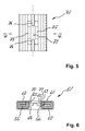
- the in the FIGS. 5 and 6 partially shown mounting bracket 51 has, in contrast to the mounting bracket 11 a sound insulating element 71, which in addition to the projecting into the slot as the fourth opening 73, lying in the longitudinal axis of the slot 74 projections 74, two further, diametrically opposed projections 75 which are transverse to the longitudinal axis of the slot in the slot of the sound insulating member 71 protrude.
- the first housing part 62 of the housing 61 has at its surrounding the slot collar 64 at corresponding points additional, the free edge of the collar 64 also superior lugs 65 which penetrate in the merged state in recesses 70 on the second housing part 67, in which the slots in the second housing part 67 surrounding collar 69 are provided.
- FIG. 1 As in FIG.
Landscapes
- Engineering & Computer Science (AREA)
- General Engineering & Computer Science (AREA)
- Mechanical Engineering (AREA)
- Chemical & Material Sciences (AREA)
- Combustion & Propulsion (AREA)
- Vehicle Interior And Exterior Ornaments, Soundproofing, And Insulation (AREA)
- Connection Of Plates (AREA)
- Motor Or Generator Frames (AREA)
- Structures Of Non-Positive Displacement Pumps (AREA)
Abstract
Description
- Die Erfindung betrifft einen Montagewinkel für eine Befestigung eines Kanals an einem Konstruktionselement mit einem Winkelelement, das einen ersten Schenkel zur Befestigung am Kanal und zumindest einen zweiten Schenkel mit einer ersten Durchführöffnung für ein Befestigungselement zur Befestigung des Montagewinkels am Konstruktionselement aufweist, mit einem ersten Gehäuseteil, das eine zweite Durchführöffnung für das Befestigungselement aufweist, und mit einem zweiten Gehäuseteil, das eine dritte Durchführöffnung für das Befestigungselement aufweist, wobei die Gehäuseteile den zweiten Schenkel an zwei gegenüberliegenden Seiten zumindest bereichsweise umgeben, und mit einem eine vierte Durchführöffnung für das Befestigungselement aufweisenden schalldämmenden Element, das den zweiten Schenkel bereichsweise umgibt und von den Gehäuseteilen entkoppelt.
- In der Installationstechnik werden beispielsweise Lüftungskanäle aus Blech mit Montagewinkeln indirekt, z. B. über Montageschienen, oder direkt an Konstruktionselementen beispielsweise eines Bauwerks befestigt, wie z. B. an Decken oder an Wänden. Zur Vermeidung der Übertragung von Körperschall werden beispielsweise schalldämmende Elemente an diesen Montagewinkeln vorgesehen, die eine Entkopplung der Befestigung ermöglichen.
- Aus der
DE 199 34 429 A1 ist ein derartiger Montagewinkel bekannt, der sich in der Praxis bewährt hat und vorteilhafte Entkopplungseigenschaften bezüglich des Körperschalls aufweist. Dieser Montagewinkel ist jedoch aufwändig in der Herstellung, so dass weiterhin ein Bedürfnis besteht, den bekannten Montagewinkel zu verbessern. - Aus der
DE 38 18 220 A1 ist ein gattungsgemässer Montagewinkel mit einem Z-förmigen Winkelelement bekannt, das an einem zweiten Schenkel eine Durchführöffnung für ein Befestigungselement aufweist, wobei der zweite Schenkel bereichsweise umfänglich von einem eine Durchführöffnung für das Befestigungselement aufweisenden schalldämmenden Element umgeben ist. Beidseitig von dem schalldämmenden Element sind jeweils ein erstes und ein zweites scheibenförmiges Gehäuseteil vorgesehen, die den zweiten Schenkel an zwei gegenüberliegenden Seiten bereichsweise umgeben und die jeweils eine Durchführöffnung für das Befestigungselement aufweisen. Das schalldämmende Element entkoppelt den zweiten Schenkel von den Gehäuseteilen. - Nachteilig an der bekannten Lösung ist, dass der Montagewinkel nur bedingt justierbar ist. Die Befestigungspunkte am Untergrund stimmen oftmals, z. B. aufgrund ungenauer Positionierung oder in Betonuntergründen aufgrund Bewehrungstreffer, mit den eigentlich erforderlichen Positionen nicht überein, so dass diese gegenüber diesen leicht verschoben sind. Dies bedingt eine gewisse Justierbarkeit der erstellten Befestigung auch im montierten Zustand des Montagewinkels, welche bei dem bekannten Montagewinkel nur bedingt, im Bereich des Durchmesserunterschieds zwischen dem Befestigungselement und der Durchführöffnung im zweiten Schenkel gegeben ist.
- Aufgabe der Erfindung ist es, einen Montagewinkel für eine Befestigung eines Kanals an einem Untergrund zu schaffen, der im montierten Zustand justierbar und gleichzeitig einfach zu fertigen ist.
- Die Aufgabe ist durch die Merkmale des unabhängigen Anspruchs gelöst. Vorteilhafte Weiterbildungen sind in den Unteransprüchen dargelegt.
- Gemäss der Erfindung sind die Durchführöffnungen in dem zumindest einen zweiten Schenkel, den Gehäuseteilen und im schalldämmenden Element Langlöcher, wobei das Langloch in dem zumindest einen zweiten Schenkel in vollständiger Überdeckung mit den Langlöchern in den Gehäuseteilen und dem Langloch in dem schalldämmenden Element liegt.
- Die Langlöcher in den genannten Teilen des Montagewinkels sind bezüglich einer gemeinsamen Durchführebene für das Befestigungselement und ihrer Längsachsen koaxial zueinander ausgerichtet beziehungsweise angeordnet. Mit den übereinander angeordneten Langlöchern ist die Verschiebbarkeit eines am Konstruktionselement direkt oder indirekt angeordneten Montagewinkels gegeben und für den Anwender klar ersichtlich. Dabei ist der Montagewinkel einfach herstellbar, da nur wenige Teile zusammengefügt werden müssen, wobei diese einen grossen Toleranzbereich aufweisen können. Dies gewährleistet neben der vorteilhaften Schallentkopplung eine wirtschaftliche Fertigung und Montage des Montagewinkels.
- Das Winkelelement ist beispielsweise L- oder Z-förmig, wobei vorteilhaft der erste Schenkel des Winkelelementes mit mehreren Bohrungen z. B. für Befestigungsschrauben zur Anordnung des Montagewinkels an einem Kanal versehen ist. Das Winkelelement ist vorteilhaft ein Stanz-/Biegeteil aus Metall.
- Das schalldämmende Element ist vorteilhaft aus einem elastischen Kunststoff z. B. in einem Extrusionsverfahren gefertigt. Das schalldämmende Element umfasst beispielsweise zwei Teilelemente die beidseitig des zumindest einen zweiten Schenkels zwischen den Gehäuseteilen vorgesehen sind. Alternativ ist das schalldämmende Element schlauchförmig ausgebildet und wird über das ein Ende des Montagewinkels auf den zumindest einen zweiten Schenkel des Winkelelementes geschoben, bis seine als Langloch ausgebildete vierte Durchführöffnung über der als Langloch ausgebildeten ersten Durchführöffnung im zumindest einen zweiten Schenkel zu liegen kommt. In einer vorteilhaften Ausführungsform des schalldämmenden Elementes ist dieses als zwei über ein Filmgelenk verbundene Flachelemente z. B. in einem Extrusionsverfahren ausgebildet, die zur Montage am zumindest einen zweiten Schenkel des Winkelelementes um diesen herum geklappt wird. Die Durchführöffnungen für das Befestigungselement in jedem Teil beziehungsweise des schalldämmenden Elementes bilden im zusammengeklappten Zustand des schalldämmenden Elementes die vierte Durchführöffnung für das Befestigungselement aus. Zur Ausbildung der Langlöcher in dem schalldämmenden Element werden diese vorteilhaft aus diesem ausgestanzt.
- Vorteilhaft sind die Gehäuseteile über ein Gelenk miteinander verbunden und werden zur Montage um das bereits vorgängig an dem zumindest einen zweiten Schenkel des Montagewinkels angeordnete schalldämmende Element herum geklappt und miteinander verbunden.
- Das Befestigungselement ist beispielsweise eine Gewindestange, die direkt am Konstruktionselement oder indirekt z. B. über eine Schienenmutter an einer Montageschiene angeordnet ist. Die Gewindestange wird mit einem Ende durch die übereinanderliegenden Durchführöffnungen geführt, wobei der Montagewinkel über Sicherungs- und Spannmuttern in der gewünschten Ausrichtung zum Konstruktionselement an der Gewindestange festgelegt wird.
- Vorzugsweise ist an jeder Durchführöffnung der Gehäuseteile ein Kragen vorgesehen, wobei die Kragen im zusammengefügten Zustand des Montagewinkels einander zugewandt sind, und das schalldämmende Element weist zumindest zwei einander diametral gegenüberliegende Vorsprünge auf, die in das Langloch des schalldämmenden Elementes ragen. Vorteilhaft umgeben die Kragen die Durchführöffnung der Gehäuseteile vollständig beziehungsweise umlaufend. Die Abmessungen der Kragen in einer von einem Gehäuseteil aufgespannten Ebene sind kleiner als die entsprechenden Abmessungen der ersten Durchführöffnung im zumindest einen zweiten Schenkel. Beim Zusammenfügen des Montagewinkels werden die in das Langloch ragenden Vorsprünge von den abragenden Kragen der Gehäuseteile umgebogen, wobei diese Materialabschnitte des schalldämmenden Elementes zwischen den Kragen der Gehäuseteile und dem Rand des Langlochs im zumindest einen zweiten Schenkel des Winkelelementes zu liegen kommen. Damit ist eine zuverlässige Schallentkopplung auch in eine Richtung quer zu der von den Durchführöffnungen definierten Durchführachse gewährleistet.
- Zudem sichern die einander zugewandten Kragen der Gehäuseteile eine vorteilhafte Entkopplung auch im verspannten Zustand des Montagewinkels. Beim Verspannen des Befestigungspunktes werden die beiden Gehäuseteile zueinander verschoben, wobei die einander zugewandten Kragen um die als Langlöcher ausgebildeten zweiten und dritten Durchführöffnungen in die erste Durchführöffnung im zumindest einen zweiten Schenkel des Winkelelementes eindringen und den maximalen Verschiebeweg der Gehäuseteile zueinander begrenzen. Damit wird die maximale Kompression des zwischen diesen Gehäuseteilen und dem zumindest einen zweiten Schenkel des Winkelelementes angeordneten schalldämmenden Elementes limitiert, was die vorteilhafte Schallentkopplung auch im festgelegten Zustand gewährleistet. Die Gehäuseteile weisen vorteilhaft randseitig abragende Umgreifabschnitte auf, die im zusammengeführten Zustand der Gehäuseteile einander zugewandt sind. Diese einander zugewandten Umgreifabschnitte begrenzen gegebenenfalls zusätzlich die maximale Verschiebbarkeit der Gehäuseteile zueinander, was z. B. auch bei einer Verspannung in eine Richtung schräg zu einer von den Gehäuseteilen aufgespannten Ebene des die Durchführöffnungen durchdringenden Befestigungselementes weiterhin eine ausreichende Schallentkopplung der Befestigung gewährleistet. Die Gehäuseteile sind vorteilhaft Stanz-/Biegeteile aus Metall.
- Bevorzugt verlaufen die zumindest zwei Vorsprünge in der Längsachse des Langlochs des schalldämmenden Elementes, was im zusammengesetzten Zustand des Montagewinkels eine vorteilhafte Schallentkopplung in Richtung der Längsachse der Langlöcher gewährleistet.
- Vorzugsweise sind zumindest zwei weitere, einander diametral gegenüberliegende Vorsprünge vorgesehen, die quer zur Längsachse des Langlochs in das Langloch des schalldämmenden Elementes ragen, was im zusammengesetzten Zustand des Montagewinkels eine vorteilhafte Schallentkopplung auch in diese Richtung gewährleistet.
- Bevorzugt ist an einem Kragen des einen Gehäuseteils zumindest eine den freien Rand dieses Kragens überragende Nase sowie am gegenüberliegenden Kragen des anderen Gehäuseteiles zumindest eine Ausnehmung zur Aufnahme der Nase vorgesehen. Die Nase ist vorteilhaft derart an dem entsprechenden Kragen angeordnet, dass beim Zusammenfügen der Gehäuseteile ein in das Langloch des schalldämmenden Elementes ragender Vorsprung von der Nase umgebogen wird und zwischen der Nase und dem Rand der ersten Durchführöffnung im zumindest einen zweiten Schenkel des Winkelelementes zu liegen kommt.
- In einer vorteilhaften Ausführungsform sind die in das Langloch des schalldämmenden Elementes ragenden Vorsprünge derart angeordnet, dass die vorgenannten Nasen beim Zusammenführen der Teile des Montagewinkels mit diesen in Anlage kommen und dabei das Umbiegen dieser Vorsprünge vorteilhaft unterstützen.
- Vorzugsweise weist das schalldämmende Element zumindest eine entlang der Längsachse seines Langlochs verlaufende Verstärkung auf, deren Höhe über einer von dem schalldämmenden Element aufgespannten Ebene zumindest dem 1.0-fachen der Dicke des schalldämmenden Elementes entspricht. Über die zumindest eine Verstärkung lässt sich die Weichheit und somit die Entkopplungseigenschaften des schalldämmenden Elementes bedarfsweise anpassen. Die Dicke der Verstärkungen gewährleistet auch bei einer Anordnung des Befestigungselementes an einem der Anschläge des Langlochs und dem daraus resultierenden Hebelarms beziehungsweise Verkippung des zumindest einen zweiten Schenkels zwischen den Gehäuseteilen eine ausreichende Schallentkopplung bei einem geringen Materialbedarf. Vorteilhaft sind mehrere Verstärkungen vorgesehen, wobei weiter vorteilhaft beidseitig und randseitig des Langlochs im schalldämmenden Element jeweils Verstärkungen vorgesehen sind, welche das schalldämmende Element in diesem Bereich vorteilhaft verstärken.
- Bevorzugt verläuft die zumindest eine Verstärkung in der Längsachse des Langlochs des schalldämmenden Elementes, womit das schalldämmende Element vorteilhafte Entkopplungs- und Stabilitätseigenschaften aufweist. Vorteilhaft sind angrenzend an das Langloch beidseitig in der Längsachse des Langlochs verlaufende Verstärkungen vorgesehen, die vorteilhaft die in das Langloch ragenden Vorsprünge ausbilden. Damit steht zwischen den Kragen der Gehäuseteile und dem Rand des Langlochs im zumindest einen zweiten Schenkel des Winkelelementes ein vorteilhafter Anteil von Material des schalldämmenden Elementes zur Schallentkopplung zur Verfügung.
- Die Erfindung wird nachstehend anhand von Ausführungsbeispielen näher erläutert. Es zeigen:
- Fig. 1
- Ein erstes Ausführungsbeispiel eines Montagewinkels in Ansicht von vorne;
- Fig. 2
- den Montagewinkel in einer Schnittdarstellung entlang der Linie II-II in
Fig. 1 ; - Fig. 3
- das schalldämmende Element in aufgeklappter Stellung in Aufsicht;
- Fig. 4
- das schalldämmende Element in Seitenansicht gem. Linie IV-IV in
Fig. 3 ; - Fig. 5
- eine Variante eines schalldämmenden Elementes in Aufsicht; und
- Fig. 6
- das schalldämmende Element in montierter Stellung in einer Schnittdarstellung entlang Linie VI-VI in
Fig. 5 . - Grundsätzlich sind in den Figuren gleiche Teile mit den gleichen Bezugszeichen versehen.
- Der in den
Figuren 1 bis 4 dargestellte Montagewinkel 11 für eine Befestigung eines Kanals an einem Konstruktionselement umfasst ein Winkelelement 12, ein Gehäuse 21 und ein schalldämmendes Element 31. - Das Winkelelement 12 ist L-förmig und weist einen ersten Schenkel 13 mit mehreren Bohrungen 14 zur Befestigung am Kanal und einen zweiten Schenkel 15 mit einer als Langloch ausgebildeten, ersten Durchführöffnung 16 für ein hier nicht dargestelltes Befestigungselement zur Befestigung des Montagewinkels 11 am Konstruktionselement auf.
- Das den zweiten Schenkel 15 umgebende Gehäuse 21 umfasst ein erstes Gehäuseteil 22 und ein zweites Gehäuseteil 27, die einteilig ausgebildet und über ein Gelenk 26 zueinander klappbar sind. Im ersten Gehäuseteil 22 ist eine als Langloch ausgebildete, zweite Durchführöffnung 23 für das Befestigungselement und im zweiten Gehäuseteil 27 ist eine ebenfalls als Langloch ausgebildete, dritte Durchführöffnung 28 für das Befestigungselement vorgesehen, wobei diese Langlöcher im zusammengesetzten Zustand des Montagewinkels 11 von dem Langloch als Durchführöffnung 16 im zweiten Schenkel 15 des Winkelelementes 12 vollständig überdeckt sind. Im zusammengeklappten Zustand des Gehäuses 21 sind die Durchführöffnungen 23 und 28 deckungsgleich zueinander. An jeder Durchführöffnung 23 und 28 ist ein umlaufender Kragen 24 bzw. 29 vorgesehen, wobei die freien Enden der Kragen 24 und 29 einander zugewandt sind. Die Abmessungen der Kragen 24 bzw. 28 in einer von einem Gehäuseteil 22 bzw. 27 aufgespannten Ebene, z. B. die Abmessung A in
Fig. 2 , sind kleiner als die entsprechenden Abmessungen der Durchführöffnung 16 im zweiten Schenkel, z. B. die Abmessung C inFig. 2 . An dem das Langloch des ersten Gehäuseteiles 22 umgebenden Kragen 24 sind einander diametral gegenüberliegende, den freien Rand des Kragens 24 überragende Nasen 25 vorgesehen, die im zusammengeführten Zustand des Gehäuses 21 in zwei am gegenüberliegenden das Langloch des zweiten Gehäuseteiles 27 umgebenden Kragen 29 vorgesehenen Ausnehmungen 30 Aufnahme finden. - Das schalldämmende Element 31 ist vorteilhaft aus einem elastischen Material extrudiert und weist ein erstes Elementteil 32 und ein zweites Elementteil 37 auf, die über ein Gelenk 41 mit einander verbunden sind. In jedes Elementteil 32 und 37 ist jeweils eine als Langloch ausgebildete Durchführöffnung 33 bzw. 38 ausgestanzt, die zusammen die vierte Durchführöffnung für das Befestigungselement ausbilden. Zur Montage des Montagewinkels 11 wird das schalldämmende Element 31 um den zweiten Schenkel 15 des Winkelelementes 12 gelegt, so dass dieser von dem schalldämmenden Element 31 weitgehend vollständig umgeben und in alle Richtungen von den Gehäuseteilen 22 und 27 entkoppelt ist. Diese Langlöcher sind im zusammengesetzten Zustand des Montagewinkels 11 von dem Langloch als Durchführöffnung 16 im zweiten Schenkel 15 des Winkelelementes 12 vollständig überdeckt.
- Weiter weist das schalldämmende Element 31 zwei einander diametral gegenüberliegende Vorsprünge 34 auf, die in das Langloch im ersten Elementteil 32 des schalldämmenden Elementes 31 ragen und in der Längsachse des Langlochs des schalldämmenden Elementes 31 verlaufen. Das schalldämmende Element 31 weist mehrere entlang der Längsachse seiner Langlöcher verlaufende Verstärkungen 35, 36 und 39, 40 auf, deren Höhe E über einer von dem schalldämmenden Element 31 aufgespannten Ebene zumindest dem 1.0-fachen der Dicke D des schalldämmenden Elementes 31 entspricht. Die Verstärkungen 35 bzw. 39 verlaufen in der Längsachse des entsprechenden Langlochs. Beidseitig des entsprechenden Langlochs als Durchführöffnung 33 bzw. 38 für das Befestigungselement ist jeweils eine entlang der Längsachse des entsprechenden Langlochs verlaufende Verstärkung 36 bzw. 40 vorgesehen. Zudem sind die seitlichen Ränder des schalldämmenden Elementes 31 ebenfalls mit entlang der Längsachse des Langlochs verlaufenden Verstärkungen versehen.
- Beim Zusammenfügen der einzelnen Teile des Montagewinkels 11 werden die in das Langloch des schalldämmenden Elementes 31 ragenden Vorsprünge 34 von dem die zweite Durchführöffnung 23 umgebenden Kragen 24 beziehungsweise von den diesen Kragen 24 überragenden Nasen 25 des ersten Gehäuseteils 22 umgebogen, so dass diese Materialabschnitte des schalldämmenden Elementes 31 zwischen den die zweite Durchführöffnung 23 umgebenden Kragen 24 des ersten Gehäuseteils 22 und dem Rand der ersten Durchführöffnung 16 im zweiten Schenkel 15 des Winkelelementes 12 zu liegen kommen.
- Der in den
Figuren 5 und 6 teilweise dargestellte Montagewinkel 51 weist im Gegensatz zum Montagewinkel 11 ein schalldämmendes Element 71 auf, das neben den in das Langloch als vierte Durchführöffnung 73 ragenden, in der Längsachse des Langlochs liegenden Vorsprüngen 74 zwei weitere, einander diametral gegenüberliegende Vorsprünge 75 aufweist, die quer zur Längsachse des Langlochs in das Langloch des schalldämmenden Elementes 71 ragen. Das erste Gehäuseteil 62 des Gehäuses 61 weist an seinem das Langloch umgebenden Kragen 64 an entsprechenden Stellen zusätzliche, den freien Rand des Kragens 64 ebenfalls überragende Nasen 65 auf, die im zusammengeführten Zustand in Ausnehmungen 70 am zweiten Gehäuseteil 67 eindringen, die in den die Langlöcher im zweiten Gehäuseteil 67 umgebenden Kragen 69 vorgesehen sind. Wie inFigur 6 ersichtlich, ist bei dieser Ausführungsform im zusammengeführten Zustand eine vorteilhafte Entkopplung mit dem zusätzlichen Materialanteil des schalldämmenden Elementes 71 in eine Richtung quer zu den Langlöchern des Montagewinkels 51 gewährleistet, da der zweite Schenkel 55 des Winkelelementes nicht nur aussenseitig sondern auch im Bereich der als Langloch ausgebildeten, ersten Durchführöffnung 56 vollständig von dem Gehäuse 61 entkoppelt ist.
Claims (7)
- Montagewinkel für eine Befestigung eines Kanals an einem Konstruktionselement mit einem Winkelelement (12), das einen ersten Schenkel (13) zur Befestigung am Kanal und zumindest einen zweiten Schenkel (15; 55) mit einer ersten Durchführöffnung (16; 56) für ein Befestigungselement zur Befestigung des Montagewinkels (11; 51) am Konstruktionselement aufweist,
mit einem ersten Gehäuseteil (22; 62), das eine zweite Durchführöffnung (23) für das Befestigungselement aufweist, und mit einem zweiten Gehäuseteil (27; 67), das eine dritte Durchführöffnung (28) für das Befestigungselement aufweist, wobei die Gehäuseteile (22, 27; 62, 67) den zweiten Schenkel (15; 55) an zwei gegenüberliegenden Seiten zumindest bereichsweise umgeben,
mit einem eine vierte Durchführöffnung (33, 38; 73) für das Befestigungselement aufweisenden schalldämmenden Element (31; 71), das den zweiten Schenkel (15; 55) bereichsweise umgibt und von den Gehäuseteilen (22, 27; 62, 67) entkoppelt, dadurch gekennzeichnet, dass
die Durchführöffnungen (16, 23, 28, 33, 38; 73) in dem zumindest einen zweiten Schenkel (15; 55), den Gehäuseteilen (22, 27; 62, 67) und im schalldämmenden Element (31; 71) Langlöcher sind, wobei das Langloch in dem zumindest einen zweiten Schenkel (15; 55) in vollständiger Überdeckung mit den Langlöchern in den Gehäuseteilen (22, 27; 62, 67) und dem Langloch in dem schalldämmenden Element (31; 71) liegt. - Montagewinkel nach Anspruch 1, dadurch gekennzeichnet, dass an jeder Durchführöffnung (23; 28) der Gehäuseteile (22, 27; 62, 67) ein Kragen (24, 29; 64, 69) vorgesehen ist, wobei die Kragen (24, 29; 64, 69) im zusammengefügten Zustand des Montagewinkels (11; 51) einander zugewandt sind, und das schalldämmende Element (31; 71) zumindest zwei einander diametral gegenüberliegende Vorsprünge (34; 74, 75) aufweist, die in das Langloch des schalldämmenden Elementes (31; 71) ragen.
- Montagewinkel nach Anspruch 2, dadurch gekennzeichnet, dass die zumindest zwei Vorsprünge (34; 74) in der Längsachse des Langlochs des schalldämmenden Elementes (31; 71) verlaufen.
- Montagewinkel nach Anspruch 2 oder 3, dadurch gekennzeichnet, dass zumindest zwei weitere, einander diametral gegenüberliegende Vorsprünge (75) vorgesehen sind, die quer zur Längsachse des Langlochs in das Langloch des schalldämmenden Elementes (71) ragen.
- Montagewinkel nach einem der Ansprüche 2 bis 4, dadurch gekennzeichnet, dass an einem Kragen (24; 64) des einen Gehäuseteils (22; 62) zumindest eine den freien Rand dieses Kragens (24; 64) überragende Nase (25; 65) sowie am gegenüberliegenden Kragen (25; 69) des anderen Gehäuseteiles (27; 67) zumindest eine Ausnehmung (30; 70) zur Aufnahme der Nase (25; 65) vorgesehen ist.
- Montagewinkel nach einem der Ansprüche 1 bis 5, dadurch gekennzeichnet, dass das schalldämmende Element (31; 71) zumindest eine entlang der Längsachse seines Langlochs verlaufende Verstärkung (35, 36, 39, 40) aufweist, deren Höhe (E) über einer von dem schalldämmenden Element (31) aufgespannten Ebene zumindest dem 1.0-fachen der Dicke (D) des schalldämmenden Elementes (31) entspricht.
- Montagewinkel nach Anspruch 6, dadurch gekennzeichnet, dass die zumindest eine Verstärkung (35, 39) in der Längsachse des Langlochs des schalldämmenden Elementes (31) verläuft.
Applications Claiming Priority (1)
| Application Number | Priority Date | Filing Date | Title |
|---|---|---|---|
| DE102007055887A DE102007055887A1 (de) | 2007-12-20 | 2007-12-20 | Montagewinkel |
Publications (2)
| Publication Number | Publication Date |
|---|---|
| EP2072872A1 true EP2072872A1 (de) | 2009-06-24 |
| EP2072872B1 EP2072872B1 (de) | 2010-06-23 |
Family
ID=40433866
Family Applications (1)
| Application Number | Title | Priority Date | Filing Date |
|---|---|---|---|
| EP08105897A Active EP2072872B1 (de) | 2007-12-20 | 2008-12-01 | Montagewinkel |
Country Status (4)
| Country | Link |
|---|---|
| EP (1) | EP2072872B1 (de) |
| AT (1) | ATE472073T1 (de) |
| DE (2) | DE102007055887A1 (de) |
| ES (1) | ES2346933T3 (de) |
Citations (6)
| Publication number | Priority date | Publication date | Assignee | Title |
|---|---|---|---|---|
| DE2458814A1 (de) * | 1973-12-20 | 1975-06-26 | Konsolen Ag | Befestigungselement |
| DE3818220A1 (de) | 1987-06-02 | 1988-12-15 | Rene Dick | Kanalhalter |
| DE4040539A1 (de) * | 1989-12-18 | 1991-06-20 | Rene Dick | Kanalhalter |
| EP1070904A2 (de) * | 1999-07-22 | 2001-01-24 | HILTI Aktiengesellschaft | Montagewinkel |
| DE20102258U1 (de) * | 2001-02-09 | 2001-11-08 | Gebhardt-Stahl GmbH, 59457 Werl | Schwingungsdämpfer als Luftkanalhalter |
| US6732982B1 (en) * | 2003-04-09 | 2004-05-11 | Bell Helicopter Textron, Inc. | Laterally adjustable clamp |
-
2007
- 2007-12-20 DE DE102007055887A patent/DE102007055887A1/de not_active Withdrawn
-
2008
- 2008-12-01 ES ES08105897T patent/ES2346933T3/es active Active
- 2008-12-01 EP EP08105897A patent/EP2072872B1/de active Active
- 2008-12-01 DE DE502008000823T patent/DE502008000823D1/de active Active
- 2008-12-01 AT AT08105897T patent/ATE472073T1/de active
Patent Citations (7)
| Publication number | Priority date | Publication date | Assignee | Title |
|---|---|---|---|---|
| DE2458814A1 (de) * | 1973-12-20 | 1975-06-26 | Konsolen Ag | Befestigungselement |
| DE3818220A1 (de) | 1987-06-02 | 1988-12-15 | Rene Dick | Kanalhalter |
| DE4040539A1 (de) * | 1989-12-18 | 1991-06-20 | Rene Dick | Kanalhalter |
| EP1070904A2 (de) * | 1999-07-22 | 2001-01-24 | HILTI Aktiengesellschaft | Montagewinkel |
| DE19934429A1 (de) | 1999-07-22 | 2001-01-25 | Hilti Ag | Montagewinkel |
| DE20102258U1 (de) * | 2001-02-09 | 2001-11-08 | Gebhardt-Stahl GmbH, 59457 Werl | Schwingungsdämpfer als Luftkanalhalter |
| US6732982B1 (en) * | 2003-04-09 | 2004-05-11 | Bell Helicopter Textron, Inc. | Laterally adjustable clamp |
Also Published As
| Publication number | Publication date |
|---|---|
| DE502008000823D1 (de) | 2010-08-05 |
| DE102007055887A1 (de) | 2009-06-25 |
| EP2072872B1 (de) | 2010-06-23 |
| ATE472073T1 (de) | 2010-07-15 |
| ES2346933T3 (es) | 2010-10-21 |
Similar Documents
| Publication | Publication Date | Title |
|---|---|---|
| WO2003039920A1 (de) | Wischanlage für eine scheibe eines kraftfahrzeugs | |
| DE102008009608A1 (de) | Einrichtung mit einem Flächenelement und einer Klemmeinrichtung | |
| DE102011106951A1 (de) | Kraftfahrzeugkarosserie | |
| EP1245889A1 (de) | Rohrschelle | |
| EP2072872B1 (de) | Montagewinkel | |
| DE102009028643A1 (de) | Verfahren zur Herstellung eines Gehäuses für ein Aggregatlager und danach hergestelltes Gehäuse | |
| DE3729824A1 (de) | Befestigungswinkel aus metall | |
| DE102015213405A1 (de) | Schaltungskomponententräger-Anordnung, Verfahren zu dessen Herstellung und Kombination mit einem Montagekörper | |
| DE202021102165U1 (de) | System zur Befestigung | |
| WO2010020420A2 (de) | Airbaganordnung | |
| EP0609973A1 (de) | Vorrichtung zur Befestigung von Deckenwinkeln | |
| EP1070904A2 (de) | Montagewinkel | |
| DE10332376A1 (de) | Verbindung zwischen einem Halteelement zum Halten eines Leitungs- und/oder Kabelstranges und zumindest einem Trägerelement an einem Fahrzeug | |
| DE202020004636U1 (de) | Gehäuse sowie ein Zuschnitt zur Herstellung eines derartigen Gehäuses | |
| EP3964655B1 (de) | Befestigungselement | |
| EP2050973A2 (de) | Befestigungselement | |
| DE202019101037U1 (de) | Reihenklemme zum Festlegen einer Reihenklemmanordnung auf einer Tragschiene | |
| DE102017204616A1 (de) | Vorrichtung zur Befestigung an einem Bauteil | |
| EP0871271B1 (de) | Montageelement für eine elektrische Anschlussdose | |
| WO2004074696A1 (de) | Halteclip | |
| EP2239393A2 (de) | Halteklammer für eine Dacheindeckungsplatte | |
| DE20209784U1 (de) | Rohrschelle | |
| WO2006034867A1 (de) | Niet- oder schraubverbindung eines kunststoffteils mit einem weiteren teil | |
| DE202006015143U1 (de) | Trägerbaueinheit zum Befestigen einer Kraftfahrzeug-Türschlosseinheit an einem Trägerteil einer Kraftfahrzeugtür | |
| DE202005001921U1 (de) | Schienenaggregat, vorgefertigte Einheit zur Herstellung eines Schienenaggregates und Verbindungselement für ein Schienenaggregat |
Legal Events
| Date | Code | Title | Description |
|---|---|---|---|
| PUAI | Public reference made under article 153(3) epc to a published international application that has entered the european phase |
Free format text: ORIGINAL CODE: 0009012 |
|
| AK | Designated contracting states |
Kind code of ref document: A1 Designated state(s): AT BE BG CH CY CZ DE DK EE ES FI FR GB GR HR HU IE IS IT LI LT LU LV MC MT NL NO PL PT RO SE SI SK TR |
|
| AX | Request for extension of the european patent |
Extension state: AL BA MK RS |
|
| GRAP | Despatch of communication of intention to grant a patent |
Free format text: ORIGINAL CODE: EPIDOSNIGR1 |
|
| 17P | Request for examination filed |
Effective date: 20091228 |
|
| AKX | Designation fees paid |
Designated state(s): AT BE BG CH CY CZ DE DK EE ES FI FR GB GR HR HU IE IS IT LI LT LU LV MC MT NL NO PL PT RO SE SI SK TR |
|
| GRAS | Grant fee paid |
Free format text: ORIGINAL CODE: EPIDOSNIGR3 |
|
| GRAA | (expected) grant |
Free format text: ORIGINAL CODE: 0009210 |
|
| AK | Designated contracting states |
Kind code of ref document: B1 Designated state(s): AT BE BG CH CY CZ DE DK EE ES FI FR GB GR HR HU IE IS IT LI LT LU LV MC MT NL NO PL PT RO SE SI SK TR |
|
| REG | Reference to a national code |
Ref country code: CH Ref legal event code: EP |
|
| REG | Reference to a national code |
Ref country code: IE Ref legal event code: FG4D Free format text: LANGUAGE OF EP DOCUMENT: GERMAN |
|
| REF | Corresponds to: |
Ref document number: 502008000823 Country of ref document: DE Date of ref document: 20100805 Kind code of ref document: P |
|
| REG | Reference to a national code |
Ref country code: ES Ref legal event code: FG2A Ref document number: 2346933 Country of ref document: ES Kind code of ref document: T3 |
|
| REG | Reference to a national code |
Ref country code: NL Ref legal event code: VDEP Effective date: 20100623 |
|
| PG25 | Lapsed in a contracting state [announced via postgrant information from national office to epo] |
Ref country code: SE Free format text: LAPSE BECAUSE OF FAILURE TO SUBMIT A TRANSLATION OF THE DESCRIPTION OR TO PAY THE FEE WITHIN THE PRESCRIBED TIME-LIMIT Effective date: 20100623 Ref country code: NO Free format text: LAPSE BECAUSE OF FAILURE TO SUBMIT A TRANSLATION OF THE DESCRIPTION OR TO PAY THE FEE WITHIN THE PRESCRIBED TIME-LIMIT Effective date: 20100923 Ref country code: LT Free format text: LAPSE BECAUSE OF FAILURE TO SUBMIT A TRANSLATION OF THE DESCRIPTION OR TO PAY THE FEE WITHIN THE PRESCRIBED TIME-LIMIT Effective date: 20100623 |
|
| LTIE | Lt: invalidation of european patent or patent extension |
Effective date: 20100623 |
|
| PG25 | Lapsed in a contracting state [announced via postgrant information from national office to epo] |
Ref country code: FI Free format text: LAPSE BECAUSE OF FAILURE TO SUBMIT A TRANSLATION OF THE DESCRIPTION OR TO PAY THE FEE WITHIN THE PRESCRIBED TIME-LIMIT Effective date: 20100623 Ref country code: SI Free format text: LAPSE BECAUSE OF FAILURE TO SUBMIT A TRANSLATION OF THE DESCRIPTION OR TO PAY THE FEE WITHIN THE PRESCRIBED TIME-LIMIT Effective date: 20100623 Ref country code: LV Free format text: LAPSE BECAUSE OF FAILURE TO SUBMIT A TRANSLATION OF THE DESCRIPTION OR TO PAY THE FEE WITHIN THE PRESCRIBED TIME-LIMIT Effective date: 20100623 Ref country code: HR Free format text: LAPSE BECAUSE OF FAILURE TO SUBMIT A TRANSLATION OF THE DESCRIPTION OR TO PAY THE FEE WITHIN THE PRESCRIBED TIME-LIMIT Effective date: 20100623 |
|
| PG25 | Lapsed in a contracting state [announced via postgrant information from national office to epo] |
Ref country code: PL Free format text: LAPSE BECAUSE OF FAILURE TO SUBMIT A TRANSLATION OF THE DESCRIPTION OR TO PAY THE FEE WITHIN THE PRESCRIBED TIME-LIMIT Effective date: 20100623 |
|
| PG25 | Lapsed in a contracting state [announced via postgrant information from national office to epo] |
Ref country code: NL Free format text: LAPSE BECAUSE OF FAILURE TO SUBMIT A TRANSLATION OF THE DESCRIPTION OR TO PAY THE FEE WITHIN THE PRESCRIBED TIME-LIMIT Effective date: 20100623 Ref country code: EE Free format text: LAPSE BECAUSE OF FAILURE TO SUBMIT A TRANSLATION OF THE DESCRIPTION OR TO PAY THE FEE WITHIN THE PRESCRIBED TIME-LIMIT Effective date: 20100623 |
|
| REG | Reference to a national code |
Ref country code: IE Ref legal event code: FD4D |
|
| PG25 | Lapsed in a contracting state [announced via postgrant information from national office to epo] |
Ref country code: RO Free format text: LAPSE BECAUSE OF FAILURE TO SUBMIT A TRANSLATION OF THE DESCRIPTION OR TO PAY THE FEE WITHIN THE PRESCRIBED TIME-LIMIT Effective date: 20100623 Ref country code: CZ Free format text: LAPSE BECAUSE OF FAILURE TO SUBMIT A TRANSLATION OF THE DESCRIPTION OR TO PAY THE FEE WITHIN THE PRESCRIBED TIME-LIMIT Effective date: 20100623 Ref country code: SK Free format text: LAPSE BECAUSE OF FAILURE TO SUBMIT A TRANSLATION OF THE DESCRIPTION OR TO PAY THE FEE WITHIN THE PRESCRIBED TIME-LIMIT Effective date: 20100623 Ref country code: CY Free format text: LAPSE BECAUSE OF FAILURE TO SUBMIT A TRANSLATION OF THE DESCRIPTION OR TO PAY THE FEE WITHIN THE PRESCRIBED TIME-LIMIT Effective date: 20100623 Ref country code: IS Free format text: LAPSE BECAUSE OF FAILURE TO SUBMIT A TRANSLATION OF THE DESCRIPTION OR TO PAY THE FEE WITHIN THE PRESCRIBED TIME-LIMIT Effective date: 20101023 |
|
| PG25 | Lapsed in a contracting state [announced via postgrant information from national office to epo] |
Ref country code: DK Free format text: LAPSE BECAUSE OF FAILURE TO SUBMIT A TRANSLATION OF THE DESCRIPTION OR TO PAY THE FEE WITHIN THE PRESCRIBED TIME-LIMIT Effective date: 20100623 Ref country code: IE Free format text: LAPSE BECAUSE OF FAILURE TO SUBMIT A TRANSLATION OF THE DESCRIPTION OR TO PAY THE FEE WITHIN THE PRESCRIBED TIME-LIMIT Effective date: 20100623 |
|
| PLBE | No opposition filed within time limit |
Free format text: ORIGINAL CODE: 0009261 |
|
| STAA | Information on the status of an ep patent application or granted ep patent |
Free format text: STATUS: NO OPPOSITION FILED WITHIN TIME LIMIT |
|
| PG25 | Lapsed in a contracting state [announced via postgrant information from national office to epo] |
Ref country code: GR Free format text: LAPSE BECAUSE OF FAILURE TO SUBMIT A TRANSLATION OF THE DESCRIPTION OR TO PAY THE FEE WITHIN THE PRESCRIBED TIME-LIMIT Effective date: 20100924 |
|
| 26N | No opposition filed |
Effective date: 20110324 |
|
| BERE | Be: lapsed |
Owner name: HILTI AKTIENGESELLSCHAFT Effective date: 20101231 |
|
| REG | Reference to a national code |
Ref country code: DE Ref legal event code: R097 Ref document number: 502008000823 Country of ref document: DE Effective date: 20110323 |
|
| PG25 | Lapsed in a contracting state [announced via postgrant information from national office to epo] |
Ref country code: MC Free format text: LAPSE BECAUSE OF NON-PAYMENT OF DUE FEES Effective date: 20101231 |
|
| PG25 | Lapsed in a contracting state [announced via postgrant information from national office to epo] |
Ref country code: BE Free format text: LAPSE BECAUSE OF NON-PAYMENT OF DUE FEES Effective date: 20101231 |
|
| PG25 | Lapsed in a contracting state [announced via postgrant information from national office to epo] |
Ref country code: MT Free format text: LAPSE BECAUSE OF FAILURE TO SUBMIT A TRANSLATION OF THE DESCRIPTION OR TO PAY THE FEE WITHIN THE PRESCRIBED TIME-LIMIT Effective date: 20100623 |
|
| PG25 | Lapsed in a contracting state [announced via postgrant information from national office to epo] |
Ref country code: BG Free format text: LAPSE BECAUSE OF FAILURE TO SUBMIT A TRANSLATION OF THE DESCRIPTION OR TO PAY THE FEE WITHIN THE PRESCRIBED TIME-LIMIT Effective date: 20100623 Ref country code: LU Free format text: LAPSE BECAUSE OF NON-PAYMENT OF DUE FEES Effective date: 20101201 Ref country code: HU Free format text: LAPSE BECAUSE OF FAILURE TO SUBMIT A TRANSLATION OF THE DESCRIPTION OR TO PAY THE FEE WITHIN THE PRESCRIBED TIME-LIMIT Effective date: 20101224 |
|
| PG25 | Lapsed in a contracting state [announced via postgrant information from national office to epo] |
Ref country code: PT Free format text: LAPSE BECAUSE OF NON-PAYMENT OF DUE FEES Effective date: 20100623 |
|
| GBPC | Gb: european patent ceased through non-payment of renewal fee |
Effective date: 20121201 |
|
| PG25 | Lapsed in a contracting state [announced via postgrant information from national office to epo] |
Ref country code: BG Free format text: LAPSE BECAUSE OF FAILURE TO SUBMIT A TRANSLATION OF THE DESCRIPTION OR TO PAY THE FEE WITHIN THE PRESCRIBED TIME-LIMIT Effective date: 20100923 |
|
| PG25 | Lapsed in a contracting state [announced via postgrant information from national office to epo] |
Ref country code: GB Free format text: LAPSE BECAUSE OF NON-PAYMENT OF DUE FEES Effective date: 20121201 |
|
| REG | Reference to a national code |
Ref country code: FR Ref legal event code: PLFP Year of fee payment: 8 |
|
| REG | Reference to a national code |
Ref country code: FR Ref legal event code: PLFP Year of fee payment: 9 |
|
| REG | Reference to a national code |
Ref country code: FR Ref legal event code: PLFP Year of fee payment: 10 |
|
| PGFP | Annual fee paid to national office [announced via postgrant information from national office to epo] |
Ref country code: TR Payment date: 20231130 Year of fee payment: 16 Ref country code: AT Payment date: 20231221 Year of fee payment: 16 |
|
| REG | Reference to a national code |
Ref country code: AT Ref legal event code: MM01 Ref document number: 472073 Country of ref document: AT Kind code of ref document: T Effective date: 20241201 |
|
| PG25 | Lapsed in a contracting state [announced via postgrant information from national office to epo] |
Ref country code: AT Free format text: LAPSE BECAUSE OF NON-PAYMENT OF DUE FEES Effective date: 20241201 |
|
| REG | Reference to a national code |
Ref country code: CH Ref legal event code: U11 Free format text: ST27 STATUS EVENT CODE: U-0-0-U10-U11 (AS PROVIDED BY THE NATIONAL OFFICE) Effective date: 20260101 |
|
| PGFP | Annual fee paid to national office [announced via postgrant information from national office to epo] |
Ref country code: DE Payment date: 20251211 Year of fee payment: 18 |
|
| PGFP | Annual fee paid to national office [announced via postgrant information from national office to epo] |
Ref country code: IT Payment date: 20251223 Year of fee payment: 18 |
|
| PGFP | Annual fee paid to national office [announced via postgrant information from national office to epo] |
Ref country code: FR Payment date: 20251222 Year of fee payment: 18 |
|
| PGFP | Annual fee paid to national office [announced via postgrant information from national office to epo] |
Ref country code: ES Payment date: 20260130 Year of fee payment: 18 |
|
| PGFP | Annual fee paid to national office [announced via postgrant information from national office to epo] |
Ref country code: CH Payment date: 20260101 Year of fee payment: 18 |