EP2072785A1 - Contrôle de la vitesse du moteur dans une machine - Google Patents
Contrôle de la vitesse du moteur dans une machine Download PDFInfo
- Publication number
- EP2072785A1 EP2072785A1 EP07123919A EP07123919A EP2072785A1 EP 2072785 A1 EP2072785 A1 EP 2072785A1 EP 07123919 A EP07123919 A EP 07123919A EP 07123919 A EP07123919 A EP 07123919A EP 2072785 A1 EP2072785 A1 EP 2072785A1
- Authority
- EP
- European Patent Office
- Prior art keywords
- speed setting
- engine speed
- engine
- controlling
- power output
- Prior art date
- Legal status (The legal status is an assumption and is not a legal conclusion. Google has not performed a legal analysis and makes no representation as to the accuracy of the status listed.)
- Granted
Links
- 238000001514 detection method Methods 0.000 claims abstract description 19
- 238000000034 method Methods 0.000 claims abstract description 12
- 230000004044 response Effects 0.000 claims abstract description 11
- 238000013507 mapping Methods 0.000 claims description 9
- 230000005540 biological transmission Effects 0.000 claims description 2
- 238000006073 displacement reaction Methods 0.000 description 20
- 230000001276 controlling effect Effects 0.000 description 14
- 238000010586 diagram Methods 0.000 description 5
- 239000012530 fluid Substances 0.000 description 5
- 239000000446 fuel Substances 0.000 description 5
- 238000011217 control strategy Methods 0.000 description 4
- 230000003071 parasitic effect Effects 0.000 description 3
- 230000009471 action Effects 0.000 description 2
- 238000001816 cooling Methods 0.000 description 2
- 230000007423 decrease Effects 0.000 description 2
- 230000003247 decreasing effect Effects 0.000 description 2
- 238000009412 basement excavation Methods 0.000 description 1
- 230000008859 change Effects 0.000 description 1
- 238000002485 combustion reaction Methods 0.000 description 1
- 230000000694 effects Effects 0.000 description 1
- 238000012986 modification Methods 0.000 description 1
- 230000004048 modification Effects 0.000 description 1
- 230000007935 neutral effect Effects 0.000 description 1
- 230000009467 reduction Effects 0.000 description 1
- 230000001105 regulatory effect Effects 0.000 description 1
Images


Classifications
-
- F—MECHANICAL ENGINEERING; LIGHTING; HEATING; WEAPONS; BLASTING
- F02—COMBUSTION ENGINES; HOT-GAS OR COMBUSTION-PRODUCT ENGINE PLANTS
- F02D—CONTROLLING COMBUSTION ENGINES
- F02D29/00—Controlling engines, such controlling being peculiar to the devices driven thereby, the devices being other than parts or accessories essential to engine operation, e.g. controlling of engines by signals external thereto
- F02D29/04—Controlling engines, such controlling being peculiar to the devices driven thereby, the devices being other than parts or accessories essential to engine operation, e.g. controlling of engines by signals external thereto peculiar to engines driving pumps
-
- F—MECHANICAL ENGINEERING; LIGHTING; HEATING; WEAPONS; BLASTING
- F04—POSITIVE - DISPLACEMENT MACHINES FOR LIQUIDS; PUMPS FOR LIQUIDS OR ELASTIC FLUIDS
- F04B—POSITIVE-DISPLACEMENT MACHINES FOR LIQUIDS; PUMPS
- F04B49/00—Control, e.g. of pump delivery, or pump pressure of, or safety measures for, machines, pumps, or pumping installations, not otherwise provided for, or of interest apart from, groups F04B1/00 - F04B47/00
- F04B49/20—Control, e.g. of pump delivery, or pump pressure of, or safety measures for, machines, pumps, or pumping installations, not otherwise provided for, or of interest apart from, groups F04B1/00 - F04B47/00 by changing the driving speed
-
- F—MECHANICAL ENGINEERING; LIGHTING; HEATING; WEAPONS; BLASTING
- F02—COMBUSTION ENGINES; HOT-GAS OR COMBUSTION-PRODUCT ENGINE PLANTS
- F02D—CONTROLLING COMBUSTION ENGINES
- F02D31/00—Use of speed-sensing governors to control combustion engines, not otherwise provided for
- F02D31/001—Electric control of rotation speed
-
- F—MECHANICAL ENGINEERING; LIGHTING; HEATING; WEAPONS; BLASTING
- F04—POSITIVE - DISPLACEMENT MACHINES FOR LIQUIDS; PUMPS FOR LIQUIDS OR ELASTIC FLUIDS
- F04B—POSITIVE-DISPLACEMENT MACHINES FOR LIQUIDS; PUMPS
- F04B2203/00—Motor parameters
- F04B2203/06—Motor parameters of internal combustion engines
- F04B2203/0604—Power
Definitions
- the present patent application generally relates to controlling the power output of an engine propelling a machine.
- the application relates for example to controlling the power output of an engine of a hydraulic work machine.
- Power control systems for hydraulic work machines for example track type tractors, track type loaders, excavators and the like, are known in the art. Also, power control systems for controlling the tracks, wheels, tires are known. The propulsion as well as drive and mobility functions of machines are controlled in the art.
- an apparatus for controlling an electro hydraulic system of a work machine having an engine that propels a variable displacement pump.
- the hydraulic system may be driven using an engine for driving the hydraulic pump and a hydraulic motor.
- Variable displacement pumps are typically used to provide hydraulic power the hydraulic system.
- the hydraulic motors may drive a plurality of work elements, also known as worktools, which may include drive system, blades, rippers and other types of work elements.
- work elements like excavators which may be useful in performing a large number of different and variant tasks, e.g., pipe laying, mass excavation, trenching, logging, and other tasks, may be driven by hydraulic motors propelled by the hydraulic power of a hydraulic system.
- hydraulic power requirements may be high.
- the hydraulic power requirements are reduced, thus requiring only a reduced power input from the engine.
- variable displacement pump is used for controlling the hydraulic flow in the hydraulic system, thus being able to react on changing power requirements.
- engine speed setting is proposed in order to operate the engine at a desired rotational speed to input the desired power into the hydraulic system.
- the engine speed signal and the pump displacement signal are evaluated and optimum working points for the engine speed and the pump displacement are calculated.
- the engine also known as prime mover or machine, may input its energy into the hydraulic system by means of the hydraulic pump.
- the input energy within the hydraulic system needs to be regulated in terms of hydraulic motor speed, torque, power, and direction of rotation.
- the pump connected to the engine generates hydraulic flow to drive the hydraulic motor, which is connected to the work tool, which may be understood as load, i.e. a power train of a drive system.
- load i.e. a power train of a drive system.
- the input power from the engine is simply transmitted to the load.
- a variable displacement pump a constant torque is possible.
- the torque of the hydraulic motor is constant at any period, because torque depends on fluid pressure and motor displacement. Increasing or decreasing pump displacement increases or decreases motor speed, respectively, while torque remains fairly constant. Therefore, the power at the hydraulic motor increases with increasing pump displacement.
- variable displacement motor with a fixed displacement pump.
- This configuration may produce a transmission that delivers a constant power. If the flow to the motor is constant, and the motor displacement is varied to maintain the product of speed and torque constant, the power delivered is constant. Decreasing motor displacement increases motor speed but decreases torque. This combination may maintain a constant power at the hydraulic motor.
- variable displacement pumps and variable displacement motors within a hydraulic system is also possible and allows for varying torque as well as power at the hydraulic motor.
- Control means may control a power output of an engine configured for propelling a machine.
- Detection means may detect a reverse driving direction operation of said machine.
- the control means may be arranged for controlling the power output of said engine in response to detecting said reversed driving direction operation.
- a work machine adapted to control an engine.
- the work machine may include control means for controlling a power output of an engine configured for propelling a machine.
- the work machine may further include detection means for detecting a reverse driving direction operation of said machine.
- the work machine may include control means being arranged for controlling power output of said engine in response to detecting said reversed driving direction operation.
- a work machine including controlling the power output of a prime mover.
- a work machine may include control means for controlling a power output of a prime mover configured for operating a machine.
- the work machine may further include detection means for identifying a reverse maneuvering operation of said machine.
- a control means may also be arranged for setting the power output of said prime mover in response to identifying said reverse maneuvering operation.
- a method for controlling an engine may include controlling a power output of an engine propelling a machine.
- the method may include detecting a reverse driving direction operation of said machine.
- the method may include reducing the power output of said engine in response to detecting said reverse driving direction operation.
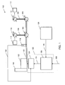
- Fig. 1 illustrates a block diagram of a hydraulic control system for a work machine
- Fig. 2 illustrates a further block diagram of a system of determining a desired engine speed setting
- Fig. 3 illustrates a graphical illustration of desired engine speed setting versus desired ground speed setting
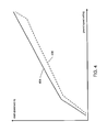
- Fig. 4 illustrates a graphical illustration of speed setting versus a desired ground speed setting
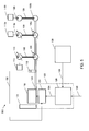
- Fig. 5 illustrates a block diagram of a further hydraulic control system for a work machine
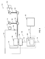
- Fig. 6 illustrates a further block diagram of another hydraulic control system for a work machine
- Fig. 7 illustrates a flowchart for operating a work machine according to embodiments.
- the present application provides for a control strategy for controlling the engine, also known as prime mover or machine, of the work machine, such that the engine speed setting is reduced, when the work machine is directed into reverse operation or in reverse operation.
- This may provide for improved engine efficiency and reduced engine noise in reverse operation. It has been found that during the return portion of the work cycle of the work machine, only a reduced performance of the hydraulic system is necessary.
- the work tools of the work machine which are operated by the hydraulic system, are mostly used in forward motion of the work machine. In reverse motion, the worktools oftentimes are inactive or have reduced activity. In other words, in reverse operation of the work machine, the worktools only require reduced power within the hydraulic system.
- the input power to the hydraulic system, input by the engine may be reduced in reverse mode. Reducing the input power may be obtained by reducing the rotational speed of the engine driving the hydraulic pumps.
- the control of the engine as well as the further below described mapping of ground speed setting to engine speed setting and dash speed setting to ground speed setting, may be activated and deactivated upon certain customers needs. It is possible, to activate the control strategy user driven.
- the described control strategy provides for reduced fuel consumption, as it has been found that work machines may be operated in reverse mode between 20 and 40% of overall operation time. Assuming 37% of reverse time, the fuel consumption may be reduced to up to 4%.
- a control strategy as will be described hereinafter allows for reducing the fuel consumption.
- the hydraulic system 100 may be applicable to any type of hydraulically or electro-hydraulically controlled work machine, for example track type tractors, track type loaders, excavators, or the like.
- the hydraulic system 100 may include an engine 102.
- the engine 102 may, for example, be a combustion engine, a hybrid engine or electrically driven engine, a solar engine, a fuel cell-engine, or the like.
- the engine 102 may also be known as prime mover or machine.
- the engine 102 may be understood as power source for the hydraulic system 100.
- the engine 102 may drive one or more hydraulic pumps 104, 106.
- the pumps 104, 106 may be variable displacement pumps or fixed displacement pumps.
- the pumps 104, 106 may deliver fluid through high pressure ducts 108 to hydraulic motors 110, 112.
- the hydraulic motors 110, 112 may be variable displacement motors or fixed displacement motors.
- the pumps 104, 106 provide for high fluid pressure within the ducts 108, for example between 40 and 500 bar.
- hydraulic motor 110 may drive worktools 114.
- Worktools 114 may, for example, be blades, or rippers, or any other type of worktools capable of being operated by a hydraulic motor.
- hydraulic motor 112 may operate a drive system 116, for example crawlers or tires or any other means for providing forward and backward motion of the work machine.
- the hydraulic system may further comprise an engine speed sensor 118.
- Engine speed sensor 118 may be arranged for sensing the rotational speed of the engine, for example, the rotational speed of the propeller shaft 120 by which engine 102 propels pumps 104, 106.
- the engine 102 may drive propeller shaft 120 at 0-4000 rpm. In common usage, the engine 102 may drive the propeller shaft 120 at 0-2500 rpm.
- the engine 102 may propel the pumps 104, 106 in order to get the hydraulic system 100 into action and to provide for hydraulic pressure within ducts 108 to drive motor 110, 112.
- Control means 122 may include an engine speed controller 124 and an engine speed setting unit 126.
- Detection means 128 allow detecting forward and reverse maneuvering operation of the work machine. Detection means 128 may be connected to a dash board including control joysticks, actuating levers, control levers, control sifters, gear levers, gear shift levers, switching levers, shift knobs, or the like. Detection means 128 allow for receiving a user input regarding driving direction and desired ground speed or speed ratio. These values may be the actual engine speed.
- Consumers 130 representing parasitic losses of the work machine.
- Consumers 130 may, for example, be cooling fans of the engine 102, electrical alternators, and the like.
- the engine speed sensor 118 feeds back an engine speed signal to engine speed controller 124 via signal line 132.
- Engine speed controller 124 received an engine speed setting signal from engine speed setting unit 126 via signal line 134.
- Engine speed setting unit 126 received from detection means 128 via signal lines 136 a desired ground speed signal.
- the desired ground speed signal may be operator commanded, or strategy commanded and provided from detection means 128.
- engine speed setting unit 126 may receive additional engine speed setting information, for example depending on over temperature of the machine, battery status, decel pedal adjustments, variable under speed settings, for example for steering assistance, and the like.
- engine speed setting unit 126 When receiving a signal indicative of reverse driving operation from detection means 128 via signal line 136, engine speed setting unit 126 provides for a reduced engine speed setting signal provided to engine speed controller 124.
- Engine speed controller 124 compares the engine speed setting signal with the actual engine speed received from engine speed sensor 118 and reduces or increases engine 102. In case the actual engine speed is higher than the engine speed setting signal requires, the engine speed of engine 102 is reduced. In case the actual engine speed is lower than the engine speed setting signal requires, the engine speed of engine 102 is increased.
- engine speed setting unit 126 received via signal line 136 desired ground speed setting signals and via signal line 138 further engine speed setting signals.
- Engine speed setting unit 126 is illustrated in more detail within Fig. 2.
- Fig. 2 illustrates engine speed setting unit 126 with input signal lines 136, 138, and output signal line 134. Via input signal line 136, engine speed setting unit 126 receives desired ground speed setting signals. These signals may be operator commanded, and provided by detection means 128. Further, via signal line 136, engine speed setting unit 126 receives a signal indicative of a reverse maneuvering operation or a desired reverse maneuvering operation of the work machine.
- Engine speed setting unit 126 puts out an engine speed setting signal via signal line 134.
- engine speed setting unit 126 comprises a first engine speed selection unit 202 and a second speed selection unit 204.
- first engine speed selection unit 202 may reduce its output engine speed setting signal, for example from 2000rpm to 1700rpm.
- the output engine speed setting signal is calculated, as illustrated in Fig. 3 .
- the engine speed setting signal is illustrated versus the desired ground speed setting.
- the desired ground speed setting signal is received within first engine speed selection unit 202.
- desired ground speeds +1, +2, +3, +4 require an output engine speed setting signal of 2000rpm.
- the engine speed setting signal may first be reduced to 1700rpm.
- the engine speed setting signal may be increased because of pump flow limit, This is to achieve original runout travel speed of the machine.
- the graph of Fig. 3 mapping the desired ground speed setting into engine speed setting is adjustable and can be adjusted to current needs. It may also happen that the engine speed setting signal is already reduced in neutral.
- second engine speed selection unit 204 may receive via signal line 138 additional engine speed setting signals.
- the output of the engine speed selection units 202, 204 is provided to comparator 206.
- comparator 206 the two engine speed setting signals received from engine speed selection units 202, 204 may be compared, and the lowest value may be passed through.
- comparison unit 206 may apply a minimum function onto the input signals.
- the output of comparison unit 206 may be provided as an engine speed setting signal on signal line 134.
- detection means 128 may receive user commanded desired speed setting, also known as dash speed settings.
- desired speed setting also known as dash speed settings.
- a reverse dash speed setting equals the same ground speed as a forward dash speed setting which is equal in absolute value
- a graph allows for mapping a dash speed setting signal into a ground speed setting signal, which mapping may be employed within detection means 128.
- a dash speed setting signal may be mapped into a corresponding ground speed setting signal.
- Graph 404 may be the mapping instruction for forward motion.
- Graph 406 may be the mapping instruction for reverse motion.
- a reverse dash speed setting results in a different ground speed setting according to graph 406 than a forward dash speed setting which is mapped according to graph 404.
- the graphs 404, 406 are tunable. For example, it is possible, to tune the dash speed setting to ground speed setting graph 406 for reverse motion in accordance with the desired ground speed to engine speed setting according to Fig. 3 . It may also be possible to use a calculation for calculating a ground speed setting signal from a dash speed setting signal.
- Fig. 5 illustrates a hydraulic system 500 being similar to a hydraulic system 100.
- Motor 112 for driving drive system 116 is now replaced by motors 112a, 112b.
- the first motor 112a drives a first drive system 116a and the second motor 112b drives a second drive system 116b.
- By providing two motors 112a, b for two drive systems 116a, b it is possible to drive the work machine with two independent axes.
- Fig. 6 illustrates a hydraulic system 600, similar to the hydraulic system 100.
- hydraulic system 600 comprises a rate limiter 602.
- Rate limiter 602 is included within engine speed setting unit 102.
- engine speed setting unit sets an engine speed setting signal in response to a desired ground speed setting signal received on signal lines 136, 138.
- Engine speed setting unit 126 may thus change the engine speed setting signal in response to changes to the input signals.
- the changes of the engine speed setting signal may be rate limited. For example, it is possible to rate limit the changes of the engine speed setting signal to +500rpm per second for for-ward motion and -500rpm per second for backward motion. Other rate limits are also possible. It is possible, to provide a rate limit as high as 2000rpm per second.
- Fig. 7 illustrates a flowchart for operating hydraulic system 100.
- engine 102 When engine 102 is started (700), hydraulic system 100 is set into action. After start (700), detection means 128 may obtain (702), input via a dash board within the work machine, a desired ground speed signal. The desired ground speed signal is provided to engine speed setting unit 126. Within engine speed setting unit 126, the obtained desired ground speed signal is evaluated (704) as has already been described in conjunction with Figs 2 , and 3 . A resulting engine speed setting signal is output to engine speed controller 124. Within engine speed controller 124, the engine speed setting signal is compared (706) with the actual engine speed received via engine speed sensor 118 and an engine speed signal is set (712) for engine 102 in order to bring the actual engine speed into conformance with the desired engine speed.
- a signal indicative of the reverse maneuvering is detected (708) within detection means 128.
- Detection means 128 output a signal indicative of the desired reverse motion.
- This signal is received (710) within engine speed setting unit 126.
- engine speed setting unit 126 sets (712) the engine speed in accordance with a graph illustrated in Fig. 3 .
- the engine speed setting signal may be reduced from 2000rpm to 1700rpm.
- Engine speed setting signal is further processed by engine speed controller 124 and in response to this signal engine 102 is operated at a reduced speed, i.e. at 1700rpm instead of 2000rpm.
- worktools 114 may require only reduced hydraulic power, as they may now be in reduced operation.
- hydraulic motor 112 may provide enough power to the drive system 116 to drive the work machine with appropriate ground speed.
- the operator does not notice that the engine 102 is driven at a reduced speed, as a ground speed is equal to the ground speed in forward motion.
- the engine 102 is operated at lower fuel consumption and reduced noise.
- parasitic loses of consumers 130 may be reduced.
- the engine fan may be operated at a reduced rate, as the engine needs less cooling. This may further reduce power losses, as parasitic losses of consumers are reduced in line with a reduction of power consumption of engine 102.
Landscapes
- Engineering & Computer Science (AREA)
- Mechanical Engineering (AREA)
- General Engineering & Computer Science (AREA)
- Chemical & Material Sciences (AREA)
- Combustion & Propulsion (AREA)
- Control Of Vehicle Engines Or Engines For Specific Uses (AREA)
- Operation Control Of Excavators (AREA)
- Control Of Electric Motors In General (AREA)
- Fluid-Pressure Circuits (AREA)
Priority Applications (7)
| Application Number | Priority Date | Filing Date | Title |
|---|---|---|---|
| EP07123919A EP2072785B1 (fr) | 2007-12-21 | 2007-12-21 | Contrôle de la vitesse du moteur dans une machine |
| AT07123919T ATE499517T1 (de) | 2007-12-21 | 2007-12-21 | Steuern der antriebsgeschwindigkeit einer maschine |
| DE602007012734T DE602007012734D1 (de) | 2007-12-21 | 2007-12-21 | Steuern der Antriebsgeschwindigkeit einer Maschine |
| RU2010130300/06A RU2499153C2 (ru) | 2007-12-21 | 2008-12-16 | Управление частотой вращения двигателя в машине |
| CN2008801216928A CN101903627A (zh) | 2007-12-21 | 2008-12-16 | 在机器中对发动机速度的控制 |
| US12/809,714 US20100299032A1 (en) | 2007-12-21 | 2008-12-16 | Control engine speed within a machine |
| PCT/US2008/013762 WO2009082446A1 (fr) | 2007-12-21 | 2008-12-16 | Commande de vitesse de moteur à l'intérieur d'une machine |
Applications Claiming Priority (1)
| Application Number | Priority Date | Filing Date | Title |
|---|---|---|---|
| EP07123919A EP2072785B1 (fr) | 2007-12-21 | 2007-12-21 | Contrôle de la vitesse du moteur dans une machine |
Publications (2)
| Publication Number | Publication Date |
|---|---|
| EP2072785A1 true EP2072785A1 (fr) | 2009-06-24 |
| EP2072785B1 EP2072785B1 (fr) | 2011-02-23 |
Family
ID=39048994
Family Applications (1)
| Application Number | Title | Priority Date | Filing Date |
|---|---|---|---|
| EP07123919A Active EP2072785B1 (fr) | 2007-12-21 | 2007-12-21 | Contrôle de la vitesse du moteur dans une machine |
Country Status (7)
| Country | Link |
|---|---|
| US (1) | US20100299032A1 (fr) |
| EP (1) | EP2072785B1 (fr) |
| CN (1) | CN101903627A (fr) |
| AT (1) | ATE499517T1 (fr) |
| DE (1) | DE602007012734D1 (fr) |
| RU (1) | RU2499153C2 (fr) |
| WO (1) | WO2009082446A1 (fr) |
Cited By (10)
| Publication number | Priority date | Publication date | Assignee | Title |
|---|---|---|---|---|
| EP2510209A4 (fr) * | 2009-12-09 | 2017-02-22 | Caterpillar, Inc. | Procédé permettant de commander un système de pompe et de moteur |
| US11270110B2 (en) | 2019-09-17 | 2022-03-08 | Boston Polarimetrics, Inc. | Systems and methods for surface modeling using polarization cues |
| US11290658B1 (en) | 2021-04-15 | 2022-03-29 | Boston Polarimetrics, Inc. | Systems and methods for camera exposure control |
| US11302012B2 (en) | 2019-11-30 | 2022-04-12 | Boston Polarimetrics, Inc. | Systems and methods for transparent object segmentation using polarization cues |
| US11525906B2 (en) | 2019-10-07 | 2022-12-13 | Intrinsic Innovation Llc | Systems and methods for augmentation of sensor systems and imaging systems with polarization |
| US11580667B2 (en) | 2020-01-29 | 2023-02-14 | Intrinsic Innovation Llc | Systems and methods for characterizing object pose detection and measurement systems |
| US11689813B2 (en) | 2021-07-01 | 2023-06-27 | Intrinsic Innovation Llc | Systems and methods for high dynamic range imaging using crossed polarizers |
| US11797863B2 (en) | 2020-01-30 | 2023-10-24 | Intrinsic Innovation Llc | Systems and methods for synthesizing data for training statistical models on different imaging modalities including polarized images |
| US11953700B2 (en) | 2020-05-27 | 2024-04-09 | Intrinsic Innovation Llc | Multi-aperture polarization optical systems using beam splitters |
| US11954886B2 (en) | 2021-04-15 | 2024-04-09 | Intrinsic Innovation Llc | Systems and methods for six-degree of freedom pose estimation of deformable objects |
Families Citing this family (6)
| Publication number | Priority date | Publication date | Assignee | Title |
|---|---|---|---|---|
| US8538645B2 (en) | 2010-06-23 | 2013-09-17 | Caterpillar Inc. | Control system having load-adjusted economy mode |
| KR101687418B1 (ko) * | 2010-12-21 | 2016-12-19 | 두산인프라코어 주식회사 | 건설중장비의 오토 아이들 제어방법 |
| JP5585487B2 (ja) | 2011-02-17 | 2014-09-10 | コベルコ建機株式会社 | ハイブリッド建設機械の動力源装置 |
| DE102012016445B3 (de) * | 2012-08-18 | 2013-05-29 | Abg Allgemeine Baumaschinen-Gesellschaft Mbh | Verfahren zum Einstellen der Drehzahl eines Verbrennungsmotors einer Straßenbaumaschine und Straßenbaumaschine hierfür |
| GB2549150B (en) | 2016-04-08 | 2019-10-09 | Caterpillar Inc | Control system and method for a machine |
| US20220289221A1 (en) | 2021-03-09 | 2022-09-15 | Deere & Company | System and method for selective derating of self-propelled work vehicle parameters based on operating modes |
Citations (5)
| Publication number | Priority date | Publication date | Assignee | Title |
|---|---|---|---|---|
| GB2281884A (en) | 1993-09-17 | 1995-03-22 | Boss Trucks Ltd | Self-propelled lift truck with engine speed control |
| JPH08246911A (ja) | 1995-03-13 | 1996-09-24 | Yanmar Diesel Engine Co Ltd | トラクターのエンジン回転数制御 |
| US5967756A (en) | 1997-07-01 | 1999-10-19 | Caterpillar Inc. | Power management control system for a hydraulic work machine |
| US20040133327A1 (en) * | 2002-01-16 | 2004-07-08 | Hidefumi Ishimoto | Electronic control systems for construction machine |
| EP1666711A1 (fr) | 2003-09-02 | 2006-06-07 | Komatsu Ltd. | Procede et dispositif de commande de la puissance de sortie d'un moteur pour machine de travail |
Family Cites Families (6)
| Publication number | Priority date | Publication date | Assignee | Title |
|---|---|---|---|---|
| SU1242633A1 (ru) * | 1984-10-02 | 1986-07-07 | Мурманский Филиал Центрального Ордена Трудового Красного Знамени Научно-Исследовательского Института Морского Флота | Устройство дл отключени подачи топлива в цилиндр дизел |
| KR0122629B1 (ko) * | 1988-05-16 | 1997-11-13 | 가타다 데츄야 | 슈우 슬립을 기초로한 적응 엔진출력 모우드 설정법 |
| SU1757929A1 (ru) * | 1989-02-09 | 1992-08-30 | Университет дружбы народов им.П.Лумумбы | Система управлени двигателем внутреннего сгорани бульдозера |
| EP1561672B1 (fr) * | 2004-02-06 | 2011-05-04 | Caterpillar Inc. | Machine de travail avec commande de direction |
| US7082361B2 (en) * | 2004-02-09 | 2006-07-25 | Cnh America Llc | Electronic speed control system for farm machines |
| US7350611B2 (en) * | 2004-06-15 | 2008-04-01 | Caterpillar Inc | Method for controlling an electric drive machine |
-
2007
- 2007-12-21 EP EP07123919A patent/EP2072785B1/fr active Active
- 2007-12-21 AT AT07123919T patent/ATE499517T1/de not_active IP Right Cessation
- 2007-12-21 DE DE602007012734T patent/DE602007012734D1/de active Active
-
2008
- 2008-12-16 RU RU2010130300/06A patent/RU2499153C2/ru active
- 2008-12-16 US US12/809,714 patent/US20100299032A1/en not_active Abandoned
- 2008-12-16 CN CN2008801216928A patent/CN101903627A/zh active Pending
- 2008-12-16 WO PCT/US2008/013762 patent/WO2009082446A1/fr active Application Filing
Patent Citations (5)
| Publication number | Priority date | Publication date | Assignee | Title |
|---|---|---|---|---|
| GB2281884A (en) | 1993-09-17 | 1995-03-22 | Boss Trucks Ltd | Self-propelled lift truck with engine speed control |
| JPH08246911A (ja) | 1995-03-13 | 1996-09-24 | Yanmar Diesel Engine Co Ltd | トラクターのエンジン回転数制御 |
| US5967756A (en) | 1997-07-01 | 1999-10-19 | Caterpillar Inc. | Power management control system for a hydraulic work machine |
| US20040133327A1 (en) * | 2002-01-16 | 2004-07-08 | Hidefumi Ishimoto | Electronic control systems for construction machine |
| EP1666711A1 (fr) | 2003-09-02 | 2006-06-07 | Komatsu Ltd. | Procede et dispositif de commande de la puissance de sortie d'un moteur pour machine de travail |
Cited By (13)
| Publication number | Priority date | Publication date | Assignee | Title |
|---|---|---|---|---|
| EP2510209A4 (fr) * | 2009-12-09 | 2017-02-22 | Caterpillar, Inc. | Procédé permettant de commander un système de pompe et de moteur |
| US11699273B2 (en) | 2019-09-17 | 2023-07-11 | Intrinsic Innovation Llc | Systems and methods for surface modeling using polarization cues |
| US11270110B2 (en) | 2019-09-17 | 2022-03-08 | Boston Polarimetrics, Inc. | Systems and methods for surface modeling using polarization cues |
| US11525906B2 (en) | 2019-10-07 | 2022-12-13 | Intrinsic Innovation Llc | Systems and methods for augmentation of sensor systems and imaging systems with polarization |
| US11842495B2 (en) | 2019-11-30 | 2023-12-12 | Intrinsic Innovation Llc | Systems and methods for transparent object segmentation using polarization cues |
| US11302012B2 (en) | 2019-11-30 | 2022-04-12 | Boston Polarimetrics, Inc. | Systems and methods for transparent object segmentation using polarization cues |
| US11580667B2 (en) | 2020-01-29 | 2023-02-14 | Intrinsic Innovation Llc | Systems and methods for characterizing object pose detection and measurement systems |
| US11797863B2 (en) | 2020-01-30 | 2023-10-24 | Intrinsic Innovation Llc | Systems and methods for synthesizing data for training statistical models on different imaging modalities including polarized images |
| US11953700B2 (en) | 2020-05-27 | 2024-04-09 | Intrinsic Innovation Llc | Multi-aperture polarization optical systems using beam splitters |
| US11683594B2 (en) | 2021-04-15 | 2023-06-20 | Intrinsic Innovation Llc | Systems and methods for camera exposure control |
| US11290658B1 (en) | 2021-04-15 | 2022-03-29 | Boston Polarimetrics, Inc. | Systems and methods for camera exposure control |
| US11954886B2 (en) | 2021-04-15 | 2024-04-09 | Intrinsic Innovation Llc | Systems and methods for six-degree of freedom pose estimation of deformable objects |
| US11689813B2 (en) | 2021-07-01 | 2023-06-27 | Intrinsic Innovation Llc | Systems and methods for high dynamic range imaging using crossed polarizers |
Also Published As
| Publication number | Publication date |
|---|---|
| RU2499153C2 (ru) | 2013-11-20 |
| ATE499517T1 (de) | 2011-03-15 |
| EP2072785B1 (fr) | 2011-02-23 |
| US20100299032A1 (en) | 2010-11-25 |
| CN101903627A (zh) | 2010-12-01 |
| RU2010130300A (ru) | 2012-01-27 |
| DE602007012734D1 (de) | 2011-04-07 |
| WO2009082446A1 (fr) | 2009-07-02 |
Similar Documents
| Publication | Publication Date | Title |
|---|---|---|
| EP2072785A1 (fr) | Contrôle de la vitesse du moteur dans une machine | |
| JP5694769B2 (ja) | 動力源回転数可変型cvt制御システム | |
| US6385970B1 (en) | Underspeed control system for a hydromechanical drive system and method of operating same | |
| US9447858B2 (en) | Hydro-mechanical continuously variable transmission for producing high torque output | |
| US8571774B2 (en) | Propulsion system with a continuously variable transmission | |
| US7849688B2 (en) | Method and apparatus for retarding an engine | |
| US5873427A (en) | Method and apparatus for controlling a load of an engine associated with a hydrostatic drive system | |
| US8660761B2 (en) | Method of effecting simultaneous displacement changes in hydrostatic drive machine | |
| US9303633B2 (en) | Over-speed control system and method | |
| US8041492B2 (en) | Engine load management for power machines | |
| EP2510209B1 (fr) | Procédé permettant de commander un système de pompe et de moteur | |
| JP2962131B2 (ja) | 静油圧−機械式変速機の制御装置 | |
| JP2010133469A (ja) | 作業車両 | |
| US8175780B2 (en) | Adaptive underspeed control | |
| JPWO2004029460A1 (ja) | 建設機械の制御装置、および入力トルク演算方法 | |
| US9945101B2 (en) | Work vehicle | |
| EP1561672B1 (fr) | Machine de travail avec commande de direction | |
| JP2008099346A (ja) | クローラ式走行装置 | |
| CN108290497B (zh) | 对车辆的压力和速度控制 | |
| AU2018274870B2 (en) | Propulsion control system with varying aggressiveness of response | |
| CN108824517B (zh) | 一种静压驱动车辆油门的自动控制方法及推土机 | |
| US10934950B2 (en) | System and method to control powertrain during directional shift | |
| WO2024084871A1 (fr) | Engin de chantier et procédé de commande d'engin de chantier | |
| JP5047630B2 (ja) | 舵取り制御を有する作業機械 |
Legal Events
| Date | Code | Title | Description |
|---|---|---|---|
| PUAI | Public reference made under article 153(3) epc to a published international application that has entered the european phase |
Free format text: ORIGINAL CODE: 0009012 |
|
| AK | Designated contracting states |
Kind code of ref document: A1 Designated state(s): AT BE BG CH CY CZ DE DK EE ES FI FR GB GR HU IE IS IT LI LT LU LV MC MT NL PL PT RO SE SI SK TR |
|
| AX | Request for extension of the european patent |
Extension state: AL BA HR MK |
|
| 17P | Request for examination filed |
Effective date: 20091126 |
|
| 17Q | First examination report despatched |
Effective date: 20091223 |
|
| AKX | Designation fees paid |
Designated state(s): AT BE BG CH CY CZ DE DK EE ES FI FR GB GR HU IE IS IT LI LT LU LV MC MT NL PL PT RO SE SI SK TR |
|
| GRAP | Despatch of communication of intention to grant a patent |
Free format text: ORIGINAL CODE: EPIDOSNIGR1 |
|
| GRAS | Grant fee paid |
Free format text: ORIGINAL CODE: EPIDOSNIGR3 |
|
| GRAA | (expected) grant |
Free format text: ORIGINAL CODE: 0009210 |
|
| AK | Designated contracting states |
Kind code of ref document: B1 Designated state(s): AT BE BG CH CY CZ DE DK EE ES FI FR GB GR HU IE IS IT LI LT LU LV MC MT NL PL PT RO SE SI SK TR |
|
| REG | Reference to a national code |
Ref country code: GB Ref legal event code: FG4D |
|
| REG | Reference to a national code |
Ref country code: CH Ref legal event code: EP |
|
| REG | Reference to a national code |
Ref country code: IE Ref legal event code: FG4D |
|
| REF | Corresponds to: |
Ref document number: 602007012734 Country of ref document: DE Date of ref document: 20110407 Kind code of ref document: P |
|
| REG | Reference to a national code |
Ref country code: DE Ref legal event code: R096 Ref document number: 602007012734 Country of ref document: DE Effective date: 20110407 |
|
| REG | Reference to a national code |
Ref country code: NL Ref legal event code: VDEP Effective date: 20110223 |
|
| LTIE | Lt: invalidation of european patent or patent extension |
Effective date: 20110223 |
|
| PG25 | Lapsed in a contracting state [announced via postgrant information from national office to epo] |
Ref country code: PT Free format text: LAPSE BECAUSE OF FAILURE TO SUBMIT A TRANSLATION OF THE DESCRIPTION OR TO PAY THE FEE WITHIN THE PRESCRIBED TIME-LIMIT Effective date: 20110623 Ref country code: GR Free format text: LAPSE BECAUSE OF FAILURE TO SUBMIT A TRANSLATION OF THE DESCRIPTION OR TO PAY THE FEE WITHIN THE PRESCRIBED TIME-LIMIT Effective date: 20110524 Ref country code: LV Free format text: LAPSE BECAUSE OF FAILURE TO SUBMIT A TRANSLATION OF THE DESCRIPTION OR TO PAY THE FEE WITHIN THE PRESCRIBED TIME-LIMIT Effective date: 20110223 Ref country code: SE Free format text: LAPSE BECAUSE OF FAILURE TO SUBMIT A TRANSLATION OF THE DESCRIPTION OR TO PAY THE FEE WITHIN THE PRESCRIBED TIME-LIMIT Effective date: 20110223 Ref country code: ES Free format text: LAPSE BECAUSE OF FAILURE TO SUBMIT A TRANSLATION OF THE DESCRIPTION OR TO PAY THE FEE WITHIN THE PRESCRIBED TIME-LIMIT Effective date: 20110603 Ref country code: LT Free format text: LAPSE BECAUSE OF FAILURE TO SUBMIT A TRANSLATION OF THE DESCRIPTION OR TO PAY THE FEE WITHIN THE PRESCRIBED TIME-LIMIT Effective date: 20110223 |
|
| PG25 | Lapsed in a contracting state [announced via postgrant information from national office to epo] |
Ref country code: BE Free format text: LAPSE BECAUSE OF FAILURE TO SUBMIT A TRANSLATION OF THE DESCRIPTION OR TO PAY THE FEE WITHIN THE PRESCRIBED TIME-LIMIT Effective date: 20110223 Ref country code: AT Free format text: LAPSE BECAUSE OF FAILURE TO SUBMIT A TRANSLATION OF THE DESCRIPTION OR TO PAY THE FEE WITHIN THE PRESCRIBED TIME-LIMIT Effective date: 20110223 Ref country code: FI Free format text: LAPSE BECAUSE OF FAILURE TO SUBMIT A TRANSLATION OF THE DESCRIPTION OR TO PAY THE FEE WITHIN THE PRESCRIBED TIME-LIMIT Effective date: 20110223 Ref country code: NL Free format text: LAPSE BECAUSE OF FAILURE TO SUBMIT A TRANSLATION OF THE DESCRIPTION OR TO PAY THE FEE WITHIN THE PRESCRIBED TIME-LIMIT Effective date: 20110223 Ref country code: BG Free format text: LAPSE BECAUSE OF FAILURE TO SUBMIT A TRANSLATION OF THE DESCRIPTION OR TO PAY THE FEE WITHIN THE PRESCRIBED TIME-LIMIT Effective date: 20110523 Ref country code: SI Free format text: LAPSE BECAUSE OF FAILURE TO SUBMIT A TRANSLATION OF THE DESCRIPTION OR TO PAY THE FEE WITHIN THE PRESCRIBED TIME-LIMIT Effective date: 20110223 Ref country code: CY Free format text: LAPSE BECAUSE OF FAILURE TO SUBMIT A TRANSLATION OF THE DESCRIPTION OR TO PAY THE FEE WITHIN THE PRESCRIBED TIME-LIMIT Effective date: 20110223 |
|
| PG25 | Lapsed in a contracting state [announced via postgrant information from national office to epo] |
Ref country code: DK Free format text: LAPSE BECAUSE OF FAILURE TO SUBMIT A TRANSLATION OF THE DESCRIPTION OR TO PAY THE FEE WITHIN THE PRESCRIBED TIME-LIMIT Effective date: 20110223 Ref country code: EE Free format text: LAPSE BECAUSE OF FAILURE TO SUBMIT A TRANSLATION OF THE DESCRIPTION OR TO PAY THE FEE WITHIN THE PRESCRIBED TIME-LIMIT Effective date: 20110223 |
|
| PG25 | Lapsed in a contracting state [announced via postgrant information from national office to epo] |
Ref country code: RO Free format text: LAPSE BECAUSE OF FAILURE TO SUBMIT A TRANSLATION OF THE DESCRIPTION OR TO PAY THE FEE WITHIN THE PRESCRIBED TIME-LIMIT Effective date: 20110223 Ref country code: SK Free format text: LAPSE BECAUSE OF FAILURE TO SUBMIT A TRANSLATION OF THE DESCRIPTION OR TO PAY THE FEE WITHIN THE PRESCRIBED TIME-LIMIT Effective date: 20110223 Ref country code: CZ Free format text: LAPSE BECAUSE OF FAILURE TO SUBMIT A TRANSLATION OF THE DESCRIPTION OR TO PAY THE FEE WITHIN THE PRESCRIBED TIME-LIMIT Effective date: 20110223 |
|
| PLBE | No opposition filed within time limit |
Free format text: ORIGINAL CODE: 0009261 |
|
| STAA | Information on the status of an ep patent application or granted ep patent |
Free format text: STATUS: NO OPPOSITION FILED WITHIN TIME LIMIT |
|
| 26N | No opposition filed |
Effective date: 20111124 |
|
| PG25 | Lapsed in a contracting state [announced via postgrant information from national office to epo] |
Ref country code: PL Free format text: LAPSE BECAUSE OF FAILURE TO SUBMIT A TRANSLATION OF THE DESCRIPTION OR TO PAY THE FEE WITHIN THE PRESCRIBED TIME-LIMIT Effective date: 20110223 |
|
| REG | Reference to a national code |
Ref country code: DE Ref legal event code: R097 Ref document number: 602007012734 Country of ref document: DE Effective date: 20111124 |
|
| PG25 | Lapsed in a contracting state [announced via postgrant information from national office to epo] |
Ref country code: MC Free format text: LAPSE BECAUSE OF NON-PAYMENT OF DUE FEES Effective date: 20111231 |
|
| REG | Reference to a national code |
Ref country code: CH Ref legal event code: PL |
|
| GBPC | Gb: european patent ceased through non-payment of renewal fee |
Effective date: 20111221 |
|
| REG | Reference to a national code |
Ref country code: IE Ref legal event code: MM4A |
|
| PG25 | Lapsed in a contracting state [announced via postgrant information from national office to epo] |
Ref country code: LI Free format text: LAPSE BECAUSE OF NON-PAYMENT OF DUE FEES Effective date: 20111231 Ref country code: CH Free format text: LAPSE BECAUSE OF NON-PAYMENT OF DUE FEES Effective date: 20111231 Ref country code: GB Free format text: LAPSE BECAUSE OF NON-PAYMENT OF DUE FEES Effective date: 20111221 Ref country code: IE Free format text: LAPSE BECAUSE OF NON-PAYMENT OF DUE FEES Effective date: 20111221 |
|
| PG25 | Lapsed in a contracting state [announced via postgrant information from national office to epo] |
Ref country code: MT Free format text: LAPSE BECAUSE OF FAILURE TO SUBMIT A TRANSLATION OF THE DESCRIPTION OR TO PAY THE FEE WITHIN THE PRESCRIBED TIME-LIMIT Effective date: 20110223 |
|
| PG25 | Lapsed in a contracting state [announced via postgrant information from national office to epo] |
Ref country code: LU Free format text: LAPSE BECAUSE OF NON-PAYMENT OF DUE FEES Effective date: 20111221 |
|
| PG25 | Lapsed in a contracting state [announced via postgrant information from national office to epo] |
Ref country code: IS Free format text: LAPSE BECAUSE OF FAILURE TO SUBMIT A TRANSLATION OF THE DESCRIPTION OR TO PAY THE FEE WITHIN THE PRESCRIBED TIME-LIMIT Effective date: 20110223 |
|
| PG25 | Lapsed in a contracting state [announced via postgrant information from national office to epo] |
Ref country code: TR Free format text: LAPSE BECAUSE OF FAILURE TO SUBMIT A TRANSLATION OF THE DESCRIPTION OR TO PAY THE FEE WITHIN THE PRESCRIBED TIME-LIMIT Effective date: 20110223 |
|
| PG25 | Lapsed in a contracting state [announced via postgrant information from national office to epo] |
Ref country code: HU Free format text: LAPSE BECAUSE OF FAILURE TO SUBMIT A TRANSLATION OF THE DESCRIPTION OR TO PAY THE FEE WITHIN THE PRESCRIBED TIME-LIMIT Effective date: 20110223 |
|
| REG | Reference to a national code |
Ref country code: FR Ref legal event code: PLFP Year of fee payment: 9 |
|
| REG | Reference to a national code |
Ref country code: FR Ref legal event code: PLFP Year of fee payment: 10 |
|
| REG | Reference to a national code |
Ref country code: FR Ref legal event code: PLFP Year of fee payment: 11 |
|
| PGFP | Annual fee paid to national office [announced via postgrant information from national office to epo] |
Ref country code: IT Payment date: 20221122 Year of fee payment: 16 |
|
| P01 | Opt-out of the competence of the unified patent court (upc) registered |
Effective date: 20230517 |
|
| PGFP | Annual fee paid to national office [announced via postgrant information from national office to epo] |
Ref country code: FR Payment date: 20231122 Year of fee payment: 17 Ref country code: DE Payment date: 20231121 Year of fee payment: 17 |