EP2072663A1 - Récipient de remplissage en eau pour un tank de liquide et procedé pour vider un tank de liquide - Google Patents
Récipient de remplissage en eau pour un tank de liquide et procedé pour vider un tank de liquide Download PDFInfo
- Publication number
- EP2072663A1 EP2072663A1 EP08170757A EP08170757A EP2072663A1 EP 2072663 A1 EP2072663 A1 EP 2072663A1 EP 08170757 A EP08170757 A EP 08170757A EP 08170757 A EP08170757 A EP 08170757A EP 2072663 A1 EP2072663 A1 EP 2072663A1
- Authority
- EP
- European Patent Office
- Prior art keywords
- container
- liquid
- chamber
- tank
- sub
- Prior art date
- Legal status (The legal status is an assumption and is not a legal conclusion. Google has not performed a legal analysis and makes no representation as to the accuracy of the status listed.)
- Withdrawn
Links
Images


Classifications
-
- D—TEXTILES; PAPER
- D06—TREATMENT OF TEXTILES OR THE LIKE; LAUNDERING; FLEXIBLE MATERIALS NOT OTHERWISE PROVIDED FOR
- D06F—LAUNDERING, DRYING, IRONING, PRESSING OR FOLDING TEXTILE ARTICLES
- D06F75/00—Hand irons
- D06F75/08—Hand irons internally heated by electricity
- D06F75/10—Hand irons internally heated by electricity with means for supplying steam to the article being ironed
- D06F75/12—Hand irons internally heated by electricity with means for supplying steam to the article being ironed the steam being produced from water supplied to the iron from an external source
Definitions
- the invention relates first of all to a water refill container for a liquid tank, in particular for a pressure vessel of a household steam ironing apparatus, with a container neck which is adapted in its outer diameter to an inner diameter of a filler neck of the pressure vessel.
- a water refill container of the type in question, in particular for filling a pressure vessel of a household steam ironing device is known from DE 10301209 A1 known.
- This container designed as a pressure vessel liquid tank is refillable or refillable.
- the user is a Provided means to hand over the refill container first fresh liquid into the tank to rinse this first, which introduced fresh rinsing liquid, if necessary, mixed with a residual liquid on the combined refill container is sucked off again. It requires correspondingly no cumbersome handling of two separate containers or the handling of a container with two different essays to perform the necessary at regular intervals rinsing of the tank. However, such flushing of the tank is quite necessary depending on the application because of possible corrosion and clogging of the tank system.
- the emptying and flushing in particular of a pressure vessel of a household steam ironing device is complex for the user according to the known solutions. Therefore, this necessary rinsing process is often neglected. Due to the residual liquid remaining in the pressure vessel, corrosion occurs in the interior of the pressure vessel over time until it eventually becomes damaged. Therefore, it is imperative that the pressure vessel rinsed regularly, that is, the residual water is emptied so that the pressure vessel does not corrode.
- the inventive combination of the container for refilling and emptying the residual by emptying the pressure vessel, this flushing process can be performed regularly and possibly inevitably.
- the suction of residual liquid can be used automatically before the actual filling process, which is supported by the separately provided chambers for storing the fresh liquid and the residual liquid and by the combination of suction and refilling.
- the water refill container is independent of the location ready for use, since this receives the fresh liquid and the absorbed residual liquid itself. Accordingly, it does not require connection to a water pipe or to an additional residual liquid tank.
- the fresh liquid sub-chamber is closed by a valve which is to be opened by an opening part when the container neck is introduced into the tank opening. Accordingly, the fresh liquid sub-chamber is activated in the course of placing the refill container on the tank, according to which immediately after a proper application of the container, the fresh liquid inlet into the tank begins.
- the opening part for releasing the fresh liquid may be connected to a cooperating with the filler neck of the tank collar or the like of the container, said collar opens on the filler neck supporting the further movement of the container in the tank opening the valve.
- the opening part is a push rod.
- such a plunger can cooperate, for example, with the filler neck of the tank, further alternatively with further associated areas of the tank.
- the pressure ram is provided in the region of the container neck and interacts with the portion of the tank bottom opposite the filler neck.
- the plunger can act on the valve via deflection.
- Preferred in this regard is an embodiment in which the pressure ram is firmly connected to the valve, so on, for example glued or welded to this. Accordingly, a preferred translation of plunger displacement to valve displacement in the ratio of 1: 1.
- a suction line For sucking residual liquid from the tank or pressure vessel, a suction line is provided which opens into the residual liquid sub-chamber.
- This suction line preferably extends in the insertion position into the area the tank bottom so as to be able to absorb in the course of the flushing process in the tank bottom area settling dirt particles.
- the residual liquid sub-chamber and the fresh liquid sub-chamber communicate with the same, resulting in filling position of the container, closed airspace.
- a rinsing process which automatically adjusts itself before the filling process can be realized, this being due to prevailing pressure conditions between the closed air space and the environment.
- the container comes in particular for the flushing but also beyond for the filling without any additional power.
- the container preferably dispenses with the energy balance completely from the energy potentials of the pressures of the various water columns of fresh liquid and residual liquid sub-chambers present in the system.
- each filling inevitably precedes a rinsing and emptying of the tank.
- the rinsing process is triggered independently. This sequence inevitably repeats each time the tank is filled.
- a rinsing process takes place, in which a fresh water subset filled in the tank is immediately absorbed again via the suction line into the residual liquid sub-chamber, wherein the dry deposits located in the tank be carried away. It is thus achieved a pure flushing, in which clean fresh liquid is contaminated with residual sediment and then immediately sucked up again to fill the cleaned tank with fresh liquid afterwards.
- the suction line is firmly connected to the valve.
- the suction line at the same time forms the plunger for valve actuation.
- the suction line is received in the container neck, which also has a fresh-fluid dispensing opening.
- the residual liquid suction opening and the fresh liquid dispensing opening are in a preferred embodiment on the container axially, that is arranged offset vertically to each other in the filling position, wherein more preferably in the filling position, the dispensing opening is viewed in the axial direction is positioned above the suction opening, from which it follows that the suction opening in the suction direction is arranged in front of the dispensing opening.
- the suction opening directed, for example, down in the direction of the tank bottom centrally, further provided for example coincident with the Be Zellnishalsachse, while further example, the dispensing opening of the dispensing line is formed by a radial opening of Be confrontnishalses.
- the residual liquid suction line and the fresh liquid dispensing line are preferably formed in the container neck as concentric lines, but may alternatively be provided in juxtaposed arrangement in the container neck.
- the dispensing line comprises the suction line like a sleeve.
- the dispensing line can also be arranged radially on the inside and the suction line can be arranged at least partially encompassing the dispensing line radially on the outside.
- the fresh liquid sub-chamber In dispensing position, the fresh liquid sub-chamber is formed above the residual liquid sub-chamber.
- the residual liquid suction line preferably passes through the fresh liquid sub-chamber, thus, for example, to form a U-shaped line section, which, after passing through the fresh liquid sub-chamber in the filling position, opens from above into the residual liquid sub-chamber.
- the automatic triggering of the flushing process as well as the automatic stop thereof and the filling of the tank with fresh water, which is carried out hereafter, are further achieved by connecting a venting line to the volume of air while passing through the fresh liquid partial chamber in the dispensing position.
- This vent line is otherwise with the residual liquid sub-chamber connected and acts in the filling position of the container as a riser for the recorded in the residual liquid sub-chamber, sucked up residual liquid which is in the riser rising water column in dependence on the decreasing in the fresh liquid sub-chamber by expiry of the fresh liquid fresh water column in proportion.
- a venting line to the volume of air while passing through the fresh liquid partial chamber in the dispensing position.
- This vent line is otherwise with the residual liquid sub-chamber connected and acts in the filling position of the container as a riser for the recorded in the residual liquid sub-chamber, sucked up residual liquid which is in the riser rising water column in dependence on the decreasing in the fresh liquid sub-chamber by expiry of the fresh liquid fresh
- the sub-chambers are separable from each other, including, for example, the two sub-chambers are screw-connected with each other.
- Other sealing occlusive connections are possible in this regard, for example, using a screw-on or alsklippsbaren annular flange which is connected to the container neck, which comprises annular flange radial collars of the sub-chambers.
- the residual liquid sub-chamber may have a separate emptying closure, which is provided, for example, with a screw cap or a stopper.
- the invention further relates to a method for emptying a liquid tank, in particular a water tank of a domestic steam ironing apparatus, wherein the tank has a filling opening and residual liquid is sucked out of the tank.
- the residual liquid is sucked into the same container, from which the fresh liquid is applied. Accordingly, it does not require the arrangement and handling of two separate containers for the suction and the introduction of fresh liquid, which further improves handling. Thus, it is provided in a development that the residual liquid is sucked in a different sub-chamber of the container than the sub-chamber in which the fresh liquid is.
- the sub-chambers within the container for example, be arranged coaxially to each other, but alternatively, for example, in axial superimposition.
- the suction of the residual liquid is preferably carried out using the weight of the fresh liquid, so on, using the prevailing pressures in the various water columns of the sub-chambers and their line sections. Accordingly, the process does not require any additional auxiliary energy.
- the energy budget is completely disputed from the energy potentials in the piping / chamber system.
- valve seal which initially closes the sub-chamber containing the fresh liquid and which is displaced into the open position in the course of insertion of the container into the filling opening of the tank.
- This valve seal acts both on the suction opening for the residual liquid and on the dispensing opening for the fresh liquid, according to which both processes are triggered only by a valve actuation.
- the container neck is introduced into the sump of the tank, which leads to an increased removal of accumulating on the bottom of the tank residues in the course of the suction process.
- FIG. 1 Shown and described is first with reference to FIG. 1 a household steam ironing device 1 with an ironing board 2 and a frame 3 carrying the ironing board. 3
- the steam ironing device 1 has a steam generating device, not shown, with a liquid tank forming a pressure vessel 4, which is connected via a steam line 5 with an iron 6 in combination.
- the pressure vessel 4 has an in FIG. 4 schematically illustrated, capped in steam operation filler neck 7 with tubular cross-section.
- a bottle-shaped water refill container 8 is provided for refilling and rinsing or residual emptying of the pressure vessel 4 of the steam generating device.
- the latter is composed of a preferably made of plastic bottle 9 and a screw-on container closure 10, which is also preferably made of a plastic material.
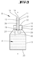
- the container 8 has centrally from the container closure 10 a tubular container neck 11. This sits at a total rotationally symmetrical design of the container 8 concentrically aligned with the container axis x.
- two lines are integrated, such as a fresh liquid dispensing line 12 and a residual liquid suction line 13.
- These two lines 12 and 13 are arranged concentrically in the container 11, wherein the dispensing line 12 surrounding the suction line 13 forms an annular channel in cross section.
- the lines 12 and 13 each have openings, such as a residual liquid suction opening 14 assigned to the central suction line 13 and a fresh liquid dispensing opening 15 associated with the dispensing line 12.
- the latter is positioned axially offset relative to the dispensing opening 15 about the outside diameter of the dispensing line 12 set back to the dispensing opening 15, so that the centrally guided suction line 13 over the corresponding dimension in the axial direction over the dispensing line 12 protrudes freely.
- the suction opening 14 is in the in the FIGS. 3 to 5 illustrated tip-side, that is positioned transversely to the axis alignment, as well as the dispensing opening 15, which describes a circular area in a plan because of the central enforcement by the suction line 13.
- Both lines 12 and 13 pass through a formed in the illustrated embodiment in the container closure 10 residual liquid sub-chamber 16, which partial chamber 16 is insulated by a separating cover 17 from the fresh liquid compartment 18 formed by the bottle 9.
- volume ratio of fresh liquid sub-chamber 18 to residual liquid sub-chamber 16 of 5: 10 to 20: 1, further example, 7: 1 or 15: 1, preferably about 10: 1 provided with a further provided, for example fresh liquid supply of about 0, 5 1.
- the in the container neck 11 radially outer fresh liquid dispensing line 12 opens, the partition 17 passing through in the fresh liquid sub-chamber 18, said mouth opening is valve-closed in the non-use position of the container 8.
- a valve plug 19 is provided, which facing the mouth opening of the dispensing line 12 tapers conically, for cooperation with a correspondingly inclined flank of the dispensing line wall.
- valve plug 19 is sealingly attached to the suction line 13 at this centrally permitting suction line 13 and not displaceable.
- valve plug 19 centrally passing through the suction line 13 is recirculated to form a 180 ° arc portion 20 with further enforcement of the partition 17 in the residual liquid compartment 16 and opens there free.
- vent pipe 21 serving as a riser vent line 21 for connecting the two sub-chambers 16 and 18, which vent pipe 21 is aligned parallel to the container axis x, so on in eccentric assignment to the axis, a side region of the residual liquid sub-chamber 16 assigned.
- the tube openings left in the free ends of the vent tube 21 are each spaced apart from the associated end face of the respective subchamber 16, 18 positioned.
- the end of the vent tube 21 remote from this end is spaced from the bottle bottom 23, which at the same time the bottom of the fresh liquid sub-chamber 18th forms.
- the bottle 9 and the fresh liquid sub-chamber 18 filled with fresh water F wherein the volume of the fresh water F stocking partial chamber 18 is used only about two-thirds, with the result that in the filling position according to the Presentation in FIG. 4 the fresh liquid sub-chamber 18 facing free end of the vent tube 21 via the fresh water level in the left closed air space 24 opens.
- the function of the refill container 8 is as follows:
- the container 8 is placed in the overhead position on the pressure vessel 4, passing through the filler neck 7 by means of the container neck 11. Accordingly, at the same time dispensing line 12 and suction 13 are guided into the pressure vessel 4, so far that the suction line 13 into the Swamp of the pressure vessel 4 is sufficient.
- the suction line 13 In the filling position, the suction line 13 is supported on the tank bottom 25 on the tip side.
- the acting as a plunger 26 suction line 13 is displaced according to the support on the tank bottom 25 with simultaneous further displacement of the container 8 in the direction of the pressure vessel 4 relative to the dispensing line 12, which on the plunger 26 and via the suction line 13, a lifting of the the suction line 13 attached valve plug 19 has the consequence.
- the previously valve-closed opening of the dispensing line 12 to the fresh liquid sub-chamber 18 is opened. Accordingly flows over the Dispensing line 12 and the end-side dispensing opening 15 fresh liquid F in the pressure vessel 4 from.
- the tank filled with residual liquid R (sub-chamber 16) is unscrewed from the bottle 9 (sub-chamber 18) and can thereafter be emptied and separated from the residual liquid sub-chamber 16 fresh liquid sub-chamber 18 again filled.
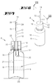
- FIGS. 3 to 5 Show the FIGS. 3 to 5 a container 8 in a schematic representation, it is in the FIGS. 6 to 12 a constructive solution of the container 8 shown in a further embodiment.
- the container closure 10 is formed in this embodiment as a screw cap on which both dispensing line 12 and suction line 13 and the arc section 20 and the valve formation and the vent tube 21 are arranged. Accordingly, after unscrewing the container closure 10, a bottle 9 is present in its original design with a bottle neck 27 and an external thread formed on the bottle neck 27. The filling opening of the bottle 9 is limited by no parts disturbing the filling; is rather free in its full cross-section.
- the suction opening 14 is also formed in the tip-side of the suction line 13 in this embodiment.
- the suction line 13 is initially rounded tip-like spherical, which tip is specifically formed by in the plan crosswise arranged webs 28, viewed in the circumferential direction between them leave the dispensing opening 15.
- the dispensing opening 15 is not strictly directed transverse to the Achserstreckung; rather goes into the subsequent sidewall sections.
- the cylindrical wall forming the dispensing line 12 is pulled in this embodiment to near the suction opening 14, enclosing the head-side Saug effetsabiteses.
- This end-side suction line section merges into a cross-section-tapered line section, which extends through the entire container neck 11 as far as the valve stopper 19.
- This reduced in outer diameter portion is the end of the suction line 13 surrounded by the compression spring 29, which is supported at the enlarged diameter end portion of the suction pipe 13 at one end.
- an abutment for the compression spring 29 is provided by a transverse to the axis extension oriented partition wall 30 in the dispensing line cylinder.
- the dispensing opening 15 is provided by a radially opening window. Accordingly, in this embodiment, an axial spacing of the suction opening 14 and dispensing opening 15 is predetermined, wherein in the filling position, the dispensing opening 15 is always positioned above the suction opening 14 as viewed in the axial direction.
- FIGS. 10 and 11 show embodiments of drain plugs 40 for opening the residual liquid compartment 16 to empty or clean.
- the partial chamber ceiling 22 may be provided with an opening 31 which is surrounded by a neck extending parallel to the container axis x, which has a peripheral bead 33 in the region of its free end. About this bead 33 in the operating position, a cap 34 bouncing tight sealing.
- the cap 34 may consist of a soft plastic material.
- a plurality of provided on a circumferential line to the axis x emptying openings 31 may be present, which are enclosed radially inwardly and radially outwardly of the axis x concentrically arranged annular walls 35 having external threads.
- the emptying openings 31 are threadedly closed together by a screw cap 36 which cooperate with the external threads of the annular walls 35.
- a central cap opening 37 of the container 11 is guided.
Applications Claiming Priority (1)
| Application Number | Priority Date | Filing Date | Title |
|---|---|---|---|
| DE200710060752 DE102007060752A1 (de) | 2007-12-17 | 2007-12-17 | Wasser-Nachfüllbehältnis für einen Flüssigkeitstank sowie Verfahren zum Entleeren eines Flüssigkeitstanks |
Publications (1)
| Publication Number | Publication Date |
|---|---|
| EP2072663A1 true EP2072663A1 (fr) | 2009-06-24 |
Family
ID=40459821
Family Applications (1)
| Application Number | Title | Priority Date | Filing Date |
|---|---|---|---|
| EP08170757A Withdrawn EP2072663A1 (fr) | 2007-12-17 | 2008-12-05 | Récipient de remplissage en eau pour un tank de liquide et procedé pour vider un tank de liquide |
Country Status (2)
| Country | Link |
|---|---|
| EP (1) | EP2072663A1 (fr) |
| DE (1) | DE102007060752A1 (fr) |
Families Citing this family (1)
| Publication number | Priority date | Publication date | Assignee | Title |
|---|---|---|---|---|
| DE102009047029A1 (de) * | 2009-11-24 | 2011-05-26 | BSH Bosch und Siemens Hausgeräte GmbH | Wasserführendes Hausgerät und Verfahren zum Fördern von Wasser in einem wasserführenden Hausgerät |
Citations (4)
| Publication number | Priority date | Publication date | Assignee | Title |
|---|---|---|---|---|
| EP0799927A2 (fr) * | 1996-04-05 | 1997-10-08 | Naomoto Industry Co., Ltd. | Fer à repasser |
| US6176026B1 (en) * | 1999-08-11 | 2001-01-23 | Simatelex Manufactory Co., Ltd. | Steam iron with power and water supplying stand |
| DE10141629A1 (de) | 2001-08-24 | 2003-03-06 | Vorwerk Co Interholding | Verfahren zum Entleeren eines Wassertanks einer Haushalts-Dampfbügelvorrichtung sowie Entleerungseinrichtung für einen derartigen Wassertank |
| DE10301209A1 (de) | 2002-01-25 | 2003-07-31 | Vorwerk Co Interholding | Wasser-Nachfüllbehältnis für ein Druckgefäß |
-
2007
- 2007-12-17 DE DE200710060752 patent/DE102007060752A1/de not_active Withdrawn
-
2008
- 2008-12-05 EP EP08170757A patent/EP2072663A1/fr not_active Withdrawn
Patent Citations (4)
| Publication number | Priority date | Publication date | Assignee | Title |
|---|---|---|---|---|
| EP0799927A2 (fr) * | 1996-04-05 | 1997-10-08 | Naomoto Industry Co., Ltd. | Fer à repasser |
| US6176026B1 (en) * | 1999-08-11 | 2001-01-23 | Simatelex Manufactory Co., Ltd. | Steam iron with power and water supplying stand |
| DE10141629A1 (de) | 2001-08-24 | 2003-03-06 | Vorwerk Co Interholding | Verfahren zum Entleeren eines Wassertanks einer Haushalts-Dampfbügelvorrichtung sowie Entleerungseinrichtung für einen derartigen Wassertank |
| DE10301209A1 (de) | 2002-01-25 | 2003-07-31 | Vorwerk Co Interholding | Wasser-Nachfüllbehältnis für ein Druckgefäß |
Also Published As
| Publication number | Publication date |
|---|---|
| DE102007060752A1 (de) | 2009-06-18 |
Similar Documents
| Publication | Publication Date | Title |
|---|---|---|
| DE60209540T2 (de) | Zapfventil | |
| DE2064074C3 (de) | Vorrichtung zur Reinigung von Dosieranlagen tür flüssige Füllgüter | |
| DE3618634A1 (de) | Ausgabevorrichtung fuer getraenke | |
| EP0882617A3 (fr) | Dispositif pour le contrôle du débit de gaz et du niveau de liquide dans un système de remplissage du carburant | |
| DE102005043745A1 (de) | Entlüftungssystem mit Siphonentleerung | |
| EP2072663A1 (fr) | Récipient de remplissage en eau pour un tank de liquide et procedé pour vider un tank de liquide | |
| DE10059217B4 (de) | Verfahen zum Abgeben von Flüssigkeitsvolumina sowie Abgabevorrichtung dafür | |
| DE102006008944B4 (de) | Zahnärztliche Spüleinheit | |
| DE102015116532A1 (de) | Verfahren sowie Behandlungsstation und Behandlungskopf zur Behandlung der Innenräume von KEGs sowie Dichtung zur Verwendung bei einer derartigen Behandlungsstation | |
| EP3517005A1 (fr) | Dispositif de distribution d'un milieu fluide | |
| DE4338296C2 (de) | Vorrichtung und Verfahren zum Füllen, insbesondere zum Wiederbefüllen, von Sprayflaschen | |
| CH679335A5 (en) | Fluid metering device for portion dispensing - has intermediate store with simultaneously-controlled discharged line and vent line | |
| DE2359986C3 (de) | Verfahren und Vorrichtung zum Abfüllen von Flüssigkeiten in Gefäße | |
| EP2141087A2 (fr) | Récipient de sortie pouvant être rempli de nouveau pour liquides | |
| DE202019000489U1 (de) | Gerät zur Entnahme einer Flüssigkeitsprobe aus einem Rohr oder Reservoir und damit ausgestattete Vorrichtung | |
| DE102008059642B4 (de) | Dosiervorrichtung | |
| DE19522297C2 (de) | Vorrichtung zum Zuführen von flüssiger Seife zu einem Schäumer | |
| DE1505623C (de) | Reguheremnchtung fur Druckwasch anlagen, insbesondere zum Reinigen von Kraftfahrzeugen | |
| EP0473841B1 (fr) | Entonnoir de remplissage | |
| DE1632055C (de) | Nachfüllbarer Behalter zur Abgabe von unter Druck stehender Flüssigkeit | |
| DE102021127287A1 (de) | Zapfhahn-Reinigungsgerät | |
| DE4006558A1 (de) | Pumpanlage zum aufnehmen von fluessigkeiten, insbesondere fluessigkeiten aus dem lebensmittelbereich | |
| DE2102030C3 (de) | Spülvorrichtung, insbesondere für Klosetts, mit einem unter Druck stehenden Tank | |
| CH686527A5 (de) | Vorrichtung zum Aufpumpen von Reifen. | |
| CH719068A1 (de) | Behälter zur Bereitstellung eines flüssigen Reinigungsmittels für Kaffeemaschinen sowie Vorrichtung und Verfahren zur Herstellung eines flüssigen Reinigungsmittels. |
Legal Events
| Date | Code | Title | Description |
|---|---|---|---|
| PUAI | Public reference made under article 153(3) epc to a published international application that has entered the european phase |
Free format text: ORIGINAL CODE: 0009012 |
|
| AK | Designated contracting states |
Kind code of ref document: A1 Designated state(s): AT BE BG CH CY CZ DE DK EE ES FI FR GB GR HR HU IE IS IT LI LT LU LV MC MT NL NO PL PT RO SE SI SK TR |
|
| AX | Request for extension of the european patent |
Extension state: AL BA MK RS |
|
| AKX | Designation fees paid | ||
| STAA | Information on the status of an ep patent application or granted ep patent |
Free format text: STATUS: THE APPLICATION IS DEEMED TO BE WITHDRAWN |
|
| 18D | Application deemed to be withdrawn |
Effective date: 20091229 |
|
| REG | Reference to a national code |
Ref country code: DE Ref legal event code: 8566 |