EP2072663A1 - Water refilling container for a liquid tank and a method to empty a liquid tank - Google Patents
Water refilling container for a liquid tank and a method to empty a liquid tank Download PDFInfo
- Publication number
- EP2072663A1 EP2072663A1 EP08170757A EP08170757A EP2072663A1 EP 2072663 A1 EP2072663 A1 EP 2072663A1 EP 08170757 A EP08170757 A EP 08170757A EP 08170757 A EP08170757 A EP 08170757A EP 2072663 A1 EP2072663 A1 EP 2072663A1
- Authority
- EP
- European Patent Office
- Prior art keywords
- container
- liquid
- chamber
- tank
- sub
- Prior art date
- Legal status (The legal status is an assumption and is not a legal conclusion. Google has not performed a legal analysis and makes no representation as to the accuracy of the status listed.)
- Withdrawn
Links
Images


Classifications
-
- D—TEXTILES; PAPER
- D06—TREATMENT OF TEXTILES OR THE LIKE; LAUNDERING; FLEXIBLE MATERIALS NOT OTHERWISE PROVIDED FOR
- D06F—LAUNDERING, DRYING, IRONING, PRESSING OR FOLDING TEXTILE ARTICLES
- D06F75/00—Hand irons
- D06F75/08—Hand irons internally heated by electricity
- D06F75/10—Hand irons internally heated by electricity with means for supplying steam to the article being ironed
- D06F75/12—Hand irons internally heated by electricity with means for supplying steam to the article being ironed the steam being produced from water supplied to the iron from an external source
Definitions
- the invention relates first of all to a water refill container for a liquid tank, in particular for a pressure vessel of a household steam ironing apparatus, with a container neck which is adapted in its outer diameter to an inner diameter of a filler neck of the pressure vessel.
- a water refill container of the type in question, in particular for filling a pressure vessel of a household steam ironing device is known from DE 10301209 A1 known.
- This container designed as a pressure vessel liquid tank is refillable or refillable.
- the user is a Provided means to hand over the refill container first fresh liquid into the tank to rinse this first, which introduced fresh rinsing liquid, if necessary, mixed with a residual liquid on the combined refill container is sucked off again. It requires correspondingly no cumbersome handling of two separate containers or the handling of a container with two different essays to perform the necessary at regular intervals rinsing of the tank. However, such flushing of the tank is quite necessary depending on the application because of possible corrosion and clogging of the tank system.
- the emptying and flushing in particular of a pressure vessel of a household steam ironing device is complex for the user according to the known solutions. Therefore, this necessary rinsing process is often neglected. Due to the residual liquid remaining in the pressure vessel, corrosion occurs in the interior of the pressure vessel over time until it eventually becomes damaged. Therefore, it is imperative that the pressure vessel rinsed regularly, that is, the residual water is emptied so that the pressure vessel does not corrode.
- the inventive combination of the container for refilling and emptying the residual by emptying the pressure vessel, this flushing process can be performed regularly and possibly inevitably.
- the suction of residual liquid can be used automatically before the actual filling process, which is supported by the separately provided chambers for storing the fresh liquid and the residual liquid and by the combination of suction and refilling.
- the water refill container is independent of the location ready for use, since this receives the fresh liquid and the absorbed residual liquid itself. Accordingly, it does not require connection to a water pipe or to an additional residual liquid tank.
- the fresh liquid sub-chamber is closed by a valve which is to be opened by an opening part when the container neck is introduced into the tank opening. Accordingly, the fresh liquid sub-chamber is activated in the course of placing the refill container on the tank, according to which immediately after a proper application of the container, the fresh liquid inlet into the tank begins.
- the opening part for releasing the fresh liquid may be connected to a cooperating with the filler neck of the tank collar or the like of the container, said collar opens on the filler neck supporting the further movement of the container in the tank opening the valve.
- the opening part is a push rod.
- such a plunger can cooperate, for example, with the filler neck of the tank, further alternatively with further associated areas of the tank.
- the pressure ram is provided in the region of the container neck and interacts with the portion of the tank bottom opposite the filler neck.
- the plunger can act on the valve via deflection.
- Preferred in this regard is an embodiment in which the pressure ram is firmly connected to the valve, so on, for example glued or welded to this. Accordingly, a preferred translation of plunger displacement to valve displacement in the ratio of 1: 1.
- a suction line For sucking residual liquid from the tank or pressure vessel, a suction line is provided which opens into the residual liquid sub-chamber.
- This suction line preferably extends in the insertion position into the area the tank bottom so as to be able to absorb in the course of the flushing process in the tank bottom area settling dirt particles.
- the residual liquid sub-chamber and the fresh liquid sub-chamber communicate with the same, resulting in filling position of the container, closed airspace.
- a rinsing process which automatically adjusts itself before the filling process can be realized, this being due to prevailing pressure conditions between the closed air space and the environment.
- the container comes in particular for the flushing but also beyond for the filling without any additional power.
- the container preferably dispenses with the energy balance completely from the energy potentials of the pressures of the various water columns of fresh liquid and residual liquid sub-chambers present in the system.
- each filling inevitably precedes a rinsing and emptying of the tank.
- the rinsing process is triggered independently. This sequence inevitably repeats each time the tank is filled.
- a rinsing process takes place, in which a fresh water subset filled in the tank is immediately absorbed again via the suction line into the residual liquid sub-chamber, wherein the dry deposits located in the tank be carried away. It is thus achieved a pure flushing, in which clean fresh liquid is contaminated with residual sediment and then immediately sucked up again to fill the cleaned tank with fresh liquid afterwards.
- the suction line is firmly connected to the valve.
- the suction line at the same time forms the plunger for valve actuation.
- the suction line is received in the container neck, which also has a fresh-fluid dispensing opening.
- the residual liquid suction opening and the fresh liquid dispensing opening are in a preferred embodiment on the container axially, that is arranged offset vertically to each other in the filling position, wherein more preferably in the filling position, the dispensing opening is viewed in the axial direction is positioned above the suction opening, from which it follows that the suction opening in the suction direction is arranged in front of the dispensing opening.
- the suction opening directed, for example, down in the direction of the tank bottom centrally, further provided for example coincident with the Be Zellnishalsachse, while further example, the dispensing opening of the dispensing line is formed by a radial opening of Be confrontnishalses.
- the residual liquid suction line and the fresh liquid dispensing line are preferably formed in the container neck as concentric lines, but may alternatively be provided in juxtaposed arrangement in the container neck.
- the dispensing line comprises the suction line like a sleeve.
- the dispensing line can also be arranged radially on the inside and the suction line can be arranged at least partially encompassing the dispensing line radially on the outside.
- the fresh liquid sub-chamber In dispensing position, the fresh liquid sub-chamber is formed above the residual liquid sub-chamber.
- the residual liquid suction line preferably passes through the fresh liquid sub-chamber, thus, for example, to form a U-shaped line section, which, after passing through the fresh liquid sub-chamber in the filling position, opens from above into the residual liquid sub-chamber.
- the automatic triggering of the flushing process as well as the automatic stop thereof and the filling of the tank with fresh water, which is carried out hereafter, are further achieved by connecting a venting line to the volume of air while passing through the fresh liquid partial chamber in the dispensing position.
- This vent line is otherwise with the residual liquid sub-chamber connected and acts in the filling position of the container as a riser for the recorded in the residual liquid sub-chamber, sucked up residual liquid which is in the riser rising water column in dependence on the decreasing in the fresh liquid sub-chamber by expiry of the fresh liquid fresh water column in proportion.
- a venting line to the volume of air while passing through the fresh liquid partial chamber in the dispensing position.
- This vent line is otherwise with the residual liquid sub-chamber connected and acts in the filling position of the container as a riser for the recorded in the residual liquid sub-chamber, sucked up residual liquid which is in the riser rising water column in dependence on the decreasing in the fresh liquid sub-chamber by expiry of the fresh liquid fresh
- the sub-chambers are separable from each other, including, for example, the two sub-chambers are screw-connected with each other.
- Other sealing occlusive connections are possible in this regard, for example, using a screw-on or alsklippsbaren annular flange which is connected to the container neck, which comprises annular flange radial collars of the sub-chambers.
- the residual liquid sub-chamber may have a separate emptying closure, which is provided, for example, with a screw cap or a stopper.
- the invention further relates to a method for emptying a liquid tank, in particular a water tank of a domestic steam ironing apparatus, wherein the tank has a filling opening and residual liquid is sucked out of the tank.
- the residual liquid is sucked into the same container, from which the fresh liquid is applied. Accordingly, it does not require the arrangement and handling of two separate containers for the suction and the introduction of fresh liquid, which further improves handling. Thus, it is provided in a development that the residual liquid is sucked in a different sub-chamber of the container than the sub-chamber in which the fresh liquid is.
- the sub-chambers within the container for example, be arranged coaxially to each other, but alternatively, for example, in axial superimposition.
- the suction of the residual liquid is preferably carried out using the weight of the fresh liquid, so on, using the prevailing pressures in the various water columns of the sub-chambers and their line sections. Accordingly, the process does not require any additional auxiliary energy.
- the energy budget is completely disputed from the energy potentials in the piping / chamber system.
- valve seal which initially closes the sub-chamber containing the fresh liquid and which is displaced into the open position in the course of insertion of the container into the filling opening of the tank.
- This valve seal acts both on the suction opening for the residual liquid and on the dispensing opening for the fresh liquid, according to which both processes are triggered only by a valve actuation.
- the container neck is introduced into the sump of the tank, which leads to an increased removal of accumulating on the bottom of the tank residues in the course of the suction process.
- FIG. 1 Shown and described is first with reference to FIG. 1 a household steam ironing device 1 with an ironing board 2 and a frame 3 carrying the ironing board. 3
- the steam ironing device 1 has a steam generating device, not shown, with a liquid tank forming a pressure vessel 4, which is connected via a steam line 5 with an iron 6 in combination.
- the pressure vessel 4 has an in FIG. 4 schematically illustrated, capped in steam operation filler neck 7 with tubular cross-section.
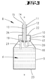
- a bottle-shaped water refill container 8 is provided for refilling and rinsing or residual emptying of the pressure vessel 4 of the steam generating device.
- the latter is composed of a preferably made of plastic bottle 9 and a screw-on container closure 10, which is also preferably made of a plastic material.
- the container 8 has centrally from the container closure 10 a tubular container neck 11. This sits at a total rotationally symmetrical design of the container 8 concentrically aligned with the container axis x.
- two lines are integrated, such as a fresh liquid dispensing line 12 and a residual liquid suction line 13.
- These two lines 12 and 13 are arranged concentrically in the container 11, wherein the dispensing line 12 surrounding the suction line 13 forms an annular channel in cross section.
- the lines 12 and 13 each have openings, such as a residual liquid suction opening 14 assigned to the central suction line 13 and a fresh liquid dispensing opening 15 associated with the dispensing line 12.
- the latter is positioned axially offset relative to the dispensing opening 15 about the outside diameter of the dispensing line 12 set back to the dispensing opening 15, so that the centrally guided suction line 13 over the corresponding dimension in the axial direction over the dispensing line 12 protrudes freely.
- the suction opening 14 is in the in the FIGS. 3 to 5 illustrated tip-side, that is positioned transversely to the axis alignment, as well as the dispensing opening 15, which describes a circular area in a plan because of the central enforcement by the suction line 13.
- Both lines 12 and 13 pass through a formed in the illustrated embodiment in the container closure 10 residual liquid sub-chamber 16, which partial chamber 16 is insulated by a separating cover 17 from the fresh liquid compartment 18 formed by the bottle 9.
- volume ratio of fresh liquid sub-chamber 18 to residual liquid sub-chamber 16 of 5: 10 to 20: 1, further example, 7: 1 or 15: 1, preferably about 10: 1 provided with a further provided, for example fresh liquid supply of about 0, 5 1.
- the in the container neck 11 radially outer fresh liquid dispensing line 12 opens, the partition 17 passing through in the fresh liquid sub-chamber 18, said mouth opening is valve-closed in the non-use position of the container 8.
- a valve plug 19 is provided, which facing the mouth opening of the dispensing line 12 tapers conically, for cooperation with a correspondingly inclined flank of the dispensing line wall.
- valve plug 19 is sealingly attached to the suction line 13 at this centrally permitting suction line 13 and not displaceable.
- valve plug 19 centrally passing through the suction line 13 is recirculated to form a 180 ° arc portion 20 with further enforcement of the partition 17 in the residual liquid compartment 16 and opens there free.
- vent pipe 21 serving as a riser vent line 21 for connecting the two sub-chambers 16 and 18, which vent pipe 21 is aligned parallel to the container axis x, so on in eccentric assignment to the axis, a side region of the residual liquid sub-chamber 16 assigned.
- the tube openings left in the free ends of the vent tube 21 are each spaced apart from the associated end face of the respective subchamber 16, 18 positioned.
- the end of the vent tube 21 remote from this end is spaced from the bottle bottom 23, which at the same time the bottom of the fresh liquid sub-chamber 18th forms.
- the bottle 9 and the fresh liquid sub-chamber 18 filled with fresh water F wherein the volume of the fresh water F stocking partial chamber 18 is used only about two-thirds, with the result that in the filling position according to the Presentation in FIG. 4 the fresh liquid sub-chamber 18 facing free end of the vent tube 21 via the fresh water level in the left closed air space 24 opens.
- the function of the refill container 8 is as follows:
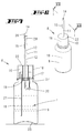
- the container 8 is placed in the overhead position on the pressure vessel 4, passing through the filler neck 7 by means of the container neck 11. Accordingly, at the same time dispensing line 12 and suction 13 are guided into the pressure vessel 4, so far that the suction line 13 into the Swamp of the pressure vessel 4 is sufficient.
- the suction line 13 In the filling position, the suction line 13 is supported on the tank bottom 25 on the tip side.
- the acting as a plunger 26 suction line 13 is displaced according to the support on the tank bottom 25 with simultaneous further displacement of the container 8 in the direction of the pressure vessel 4 relative to the dispensing line 12, which on the plunger 26 and via the suction line 13, a lifting of the the suction line 13 attached valve plug 19 has the consequence.
- the previously valve-closed opening of the dispensing line 12 to the fresh liquid sub-chamber 18 is opened. Accordingly flows over the Dispensing line 12 and the end-side dispensing opening 15 fresh liquid F in the pressure vessel 4 from.
- the tank filled with residual liquid R (sub-chamber 16) is unscrewed from the bottle 9 (sub-chamber 18) and can thereafter be emptied and separated from the residual liquid sub-chamber 16 fresh liquid sub-chamber 18 again filled.
- FIGS. 3 to 5 Show the FIGS. 3 to 5 a container 8 in a schematic representation, it is in the FIGS. 6 to 12 a constructive solution of the container 8 shown in a further embodiment.
- the container closure 10 is formed in this embodiment as a screw cap on which both dispensing line 12 and suction line 13 and the arc section 20 and the valve formation and the vent tube 21 are arranged. Accordingly, after unscrewing the container closure 10, a bottle 9 is present in its original design with a bottle neck 27 and an external thread formed on the bottle neck 27. The filling opening of the bottle 9 is limited by no parts disturbing the filling; is rather free in its full cross-section.
- the suction opening 14 is also formed in the tip-side of the suction line 13 in this embodiment.
- the suction line 13 is initially rounded tip-like spherical, which tip is specifically formed by in the plan crosswise arranged webs 28, viewed in the circumferential direction between them leave the dispensing opening 15.
- the dispensing opening 15 is not strictly directed transverse to the Achserstreckung; rather goes into the subsequent sidewall sections.
- the cylindrical wall forming the dispensing line 12 is pulled in this embodiment to near the suction opening 14, enclosing the head-side Saug effetsabiteses.
- This end-side suction line section merges into a cross-section-tapered line section, which extends through the entire container neck 11 as far as the valve stopper 19.
- This reduced in outer diameter portion is the end of the suction line 13 surrounded by the compression spring 29, which is supported at the enlarged diameter end portion of the suction pipe 13 at one end.
- an abutment for the compression spring 29 is provided by a transverse to the axis extension oriented partition wall 30 in the dispensing line cylinder.
- the dispensing opening 15 is provided by a radially opening window. Accordingly, in this embodiment, an axial spacing of the suction opening 14 and dispensing opening 15 is predetermined, wherein in the filling position, the dispensing opening 15 is always positioned above the suction opening 14 as viewed in the axial direction.
- FIGS. 10 and 11 show embodiments of drain plugs 40 for opening the residual liquid compartment 16 to empty or clean.
- the partial chamber ceiling 22 may be provided with an opening 31 which is surrounded by a neck extending parallel to the container axis x, which has a peripheral bead 33 in the region of its free end. About this bead 33 in the operating position, a cap 34 bouncing tight sealing.
- the cap 34 may consist of a soft plastic material.
- a plurality of provided on a circumferential line to the axis x emptying openings 31 may be present, which are enclosed radially inwardly and radially outwardly of the axis x concentrically arranged annular walls 35 having external threads.
- the emptying openings 31 are threadedly closed together by a screw cap 36 which cooperate with the external threads of the annular walls 35.
- a central cap opening 37 of the container 11 is guided.
Abstract
Description
Die Erfindung betrifft zunächst ein Wasser-Nachfüllbehältnis für einen Flüssigkeitstank, insbesondere für ein Druckgefäß einer Haushalts-Dampfbügelvorrichtung, mit einem Behältnishals, der in seinem Außendurchmesser an einen Innendurchmesser eines Einfüllstutzens des Druckgefäßes angepasst ist.The invention relates first of all to a water refill container for a liquid tank, in particular for a pressure vessel of a household steam ironing apparatus, with a container neck which is adapted in its outer diameter to an inner diameter of a filler neck of the pressure vessel.
Ein Wasser-Nachfüllbehältnis der in Rede stehenden Art, insbesondere zur Befüllung eines Druckgefäßes einer Haushalts-Dampfbügelvorrichtung ist aus der
Im Hinblick auf den bekannten Stand der Technik wird eine technische Problematik der Erfindung darin gesehen, ein Wasser-Nachfüllbehältnis der in Rede stehenden Art insbesondere handhabungstechnisch weiter zu verbessern.In view of the known prior art, a technical problem of the invention is seen in a water refill container of the type in question in particular handling technology to further improve.
Diese Problematik ist zunächst und im Wesentlichen durch den Gegenstand des Anspruchs 1 gelöst, wobei darauf abgestellt ist, dass das Behältnis mit einer Saugvorrichtung zum Aussaugen von Restflüssigkeit aus dem Tank kombiniert ist, wobei weiter in dem Behältnis eine Teilkammer für die Frischflüssigkeit und eine davon flüssigkeitsmäßig getrennte Teilkammer für die Restflüssigkeit ausgebildet sind. Zufolge dieser Ausgestaltung ist ein Nachfüllbehältnis geschaffen, welches zugleich der Absaugung von insbesondere Restflüssigkeit aus dem Tank dienen kann. Entsprechend liegt ein kombiniertes Behältnis vor, was insgesamt dem Benutzer den Umgang erleichtert. So kann dieser mittels dieses Nachfüllbehältnisses noch in dem Tank befindliche Restflüssigkeit zunächst aussaugen, dies weiter unter Mitaufsaugen etwaiger Rückstände wie Schmutzpartikel in dem Tank. Die aufgesaugte Restflüssigkeit wird in einer gesonderten Kammer des Nachfüllbehältnisses aufbewahrt. Eine Vermengung mit der Frischflüssigkeit wird hierdurch vermieden. Zudem wird dem Benutzer ein Mittel an die Hand gegeben, über das Nachfüllbehältnis zunächst Frischflüssigkeit in den Tank zu geben, um diesen zunächst zu spülen, welche eingebrachte Frisch-Spülflüssigkeit gegebenenfalls vermengt mit einer Restflüssigkeit über das kombinierte Nachfüllbehältnis wieder abgesaugt wird. Es bedarf entsprechend keines umständlichen Handhabens von zwei getrennten Behältnissen bzw. der Handhabung eines Behältnisses mit zwei verschiedenen Aufsätzen, um den in bevorzugt regelmäßigen Abständen nötigen Spülvorgang des Tankes durchzuführen. Eine solche Spülung des Tankes ist jedoch je nach Anwendungsfall wegen möglicher Korrosion und Verstopfung des Tanksystems durchaus nötig.This problem is initially and essentially solved by the subject matter of
Die Restentleerung und Spülung insbesondere eines Druckgefäßes einer Haushalts-Dampfbügelvorrichtung ist für den Benutzer gemäß den bekannten Lösungen aufwändig. Daher wird dieser notwendige Spülprozess häufig vernachlässigt. Durch die im Druckgefäß verbleibende Restflüssigkeit entsteht über die Zeit Korrosion im Innern des Druckgefäßes, bis dieses gegebenenfalls Schaden nimmt. Daher ist es zwingend nötig, dass das Druckgefäß regelmäßig gespült, das heißt das Restwasser entleert wird, damit das Druckgefäß nicht korrodiert. Durch die erfindungsgemäße Kombination des Behältnisses zum Nachfüllen und Restentleeren durch Aussaugen des Druckgefäßes kann dieser Spülvorgang regelmäßig und gegebenenfalls zwangsläufig durchgeführt werden. Das Absaugen von Restflüssigkeit kann hierbei vor dem eigentlichen Befüllvorgang automatisiert einsetzen, was durch die getrennt vorgesehenen Kammern zur Aufbewahrung der Frischflüssigkeit und der Restflüssigkeit und durch die Kombination von Saugvorrichtung und Nachfüllvorrichtung unterstützt wird. In vorteilhafter Weise ist das Wasser-Nachfüllbehältnis unabhängig vom Standort einsatzbereit, da dieses die Frischflüssigkeit und die aufgesaugte Restflüssigkeit selbst aufnimmt. Es bedarf entsprechend nicht dem Anschluss an eine Wasserleitung bzw. an einem zusätzlichen Restflüssigkeitstank.The emptying and flushing in particular of a pressure vessel of a household steam ironing device is complex for the user according to the known solutions. Therefore, this necessary rinsing process is often neglected. Due to the residual liquid remaining in the pressure vessel, corrosion occurs in the interior of the pressure vessel over time until it eventually becomes damaged. Therefore, it is imperative that the pressure vessel rinsed regularly, that is, the residual water is emptied so that the pressure vessel does not corrode. The inventive combination of the container for refilling and emptying the residual by emptying the pressure vessel, this flushing process can be performed regularly and possibly inevitably. The suction of residual liquid can be used automatically before the actual filling process, which is supported by the separately provided chambers for storing the fresh liquid and the residual liquid and by the combination of suction and refilling. Advantageously, the water refill container is independent of the location ready for use, since this receives the fresh liquid and the absorbed residual liquid itself. Accordingly, it does not require connection to a water pipe or to an additional residual liquid tank.
Die Gegenstände der weiteren Ansprüche sind nachstehend in Bezug zu dem Gegenstand des Anspruchs 1 erläutert, können aber auch in ihrer unabhängigen Formulierung von Bedeutung sein.The subjects of the further claims are explained below in relation to the subject matter of
So ist in einer Weiterbildung des Erfindungsgegenstandes vorgesehen, dass die Frischflüssigkeits-Teilkammer durch ein Ventil verschlossen ist, das beim Einführen des Behältnishalses in die Tanköffnung durch ein Öffnungsteil zu öffnen ist. Entsprechend wird die Frischflüssigkeits-Teilkammer im Zuge des Aufsetzens des Nachfüllbehältnisses auf den Tank aktiviert, zufolge dessen nach einem ordnungsgemäßen Ansetzen des Behältnisses unmittelbar der Frischflüssigkeitseinlauf in den Tank einsetzt. Das Öffnungsteil zur Freigabe der Frischflüssigkeit kann mit einem mit dem Einfüllstutzen des Tanks zusammenwirkenden Kragen oder dergleichen des Behältnisses verbunden sein, wobei dieser Kragen an dem Einfüllstutzen sich abstützend bei weiterer Verlagerung des Behältnishalses in die Tanköffnung das Ventil öffnet. In einer Weiterbildung des Erfindungsgegenstandes ist das Öffnungsteil ein Druckstößel. Auch ein solcher Druckstößel kann beispielsweise mit dem Einfüllstutzen des Tankes zusammenwirken, weiter alternativ mit weiter zugeordneten Bereichen des Tankes. So ist in einer bevorzugten Ausgestaltung der Druckstößel im Bereich des Behältnishalses vorgesehen und wirkt mit dem dem Einfüllstutzen gegenüberliegenden Abschnitt des Tankbodens zusammen.Thus, in a further development of the subject invention, it is provided that the fresh liquid sub-chamber is closed by a valve which is to be opened by an opening part when the container neck is introduced into the tank opening. Accordingly, the fresh liquid sub-chamber is activated in the course of placing the refill container on the tank, according to which immediately after a proper application of the container, the fresh liquid inlet into the tank begins. The opening part for releasing the fresh liquid may be connected to a cooperating with the filler neck of the tank collar or the like of the container, said collar opens on the filler neck supporting the further movement of the container in the tank opening the valve. In a development of the subject invention, the opening part is a push rod. Also, such a plunger can cooperate, for example, with the filler neck of the tank, further alternatively with further associated areas of the tank. Thus, in a preferred embodiment, the pressure ram is provided in the region of the container neck and interacts with the portion of the tank bottom opposite the filler neck.
Der Druckstößel kann über Umlenkmittel auf das Ventil einwirken. Bevorzugt wird diesbezüglich eine Ausgestaltung, bei welcher der Druckstößel fest mit dem Ventil verbunden ist, so weiter beispielsweise mit diesem verklebt oder verschweißt ist. Entsprechend erfolgt eine bevorzugte Übersetzung von Druckstößelverlagerung zu Ventilverlagerung im Verhältnis von 1 : 1.The plunger can act on the valve via deflection. Preferred in this regard is an embodiment in which the pressure ram is firmly connected to the valve, so on, for example glued or welded to this. Accordingly, a preferred translation of plunger displacement to valve displacement in the ratio of 1: 1.
Zum Aufsaugen von Restflüssigkeit aus dem Tank bzw. Druckgefäß ist eine Saugleitung vorgesehen, die in die Restflüssigkeits-Teilkammer mündet. Diese Saugleitung erstreckt sich bevorzugt in der Einsatzstellung bis in den Bereich des Tankbodens, um so im Zuge des Spülvorganges im Tankbodenbereich sich absetzende Schmutzpartikel mit aufsaugen zu können.For sucking residual liquid from the tank or pressure vessel, a suction line is provided which opens into the residual liquid sub-chamber. This suction line preferably extends in the insertion position into the area the tank bottom so as to be able to absorb in the course of the flushing process in the tank bottom area settling dirt particles.
Als besonders vorteilhaft erweist sich eine Ausgestaltung, bei welcher die Restflüssigkeits-Teilkammer und die Frischflüssigkeits-Teilkammer mit demselben sich in Füllstellung des Behältnisses ergebenden, abgeschlossenen Luftraum kommunizieren. Zufolge dieser Ausgestaltung ist ein automatisch sich vor dem Befüllvorgang einstellender Spülvorgang realisierbar, dies aufgrund vorherrschender Druckverhältnisse zwischen dem abgeschlossenen Luftraum und der Umgebung. Das Behältnis kommt insbesondere für den Spülvorgang aber auch darüber hinaus für den Befüllvorgang ohne weitere Hilfsenergie aus. Das Behältnis bestreitet den Energiehaushalt bevorzugt komplett aus den Energiepotentialen der in dem System vorhandenen Drücke der verschiedenen Wassersäulen von Frischflüssigkeit und Restflüssigkeit-Teilkammern. Entsprechend ist durch diese Kopplung der Teilkammern in der Befüllstellung erreicht, dass jedem Befüllvorgang unweigerlich ein Spülvorgang und eine Restentleerung des Tankes vorausgeht. Der Spülvorgang wird entsprechend selbstständig ausgelöst. Dieser Ablauf wiederholt sich zwangsläufig bei jedem Befüllvorgang des Tanks. Im Falle eine komplett leeren Tanks, in dem kein Restwasser mehr vorhanden ist, findet ein Spülvorgang statt, bei welchem eine in den Tank eingefüllte Frischwasser-Teilmenge sofort wieder über die Saugleitung in die Restflüssigkeits-Teilkammer aufgesogen wird, wobei die in dem Tank befindlichen Trockenablagerungen mitgerissen werden. Es ist somit ein reiner Spülvorgang erreicht, bei welchem saubere Frischflüssigkeit mit Restsediment verunreinigt wird und dann sofort wieder aufgesaugt wird, um nachher den gereinigten Tank mit Frischflüssigkeit zu befüllen.Particularly advantageous is an embodiment in which the residual liquid sub-chamber and the fresh liquid sub-chamber communicate with the same, resulting in filling position of the container, closed airspace. As a result of this refinement, a rinsing process which automatically adjusts itself before the filling process can be realized, this being due to prevailing pressure conditions between the closed air space and the environment. The container comes in particular for the flushing but also beyond for the filling without any additional power. The container preferably dispenses with the energy balance completely from the energy potentials of the pressures of the various water columns of fresh liquid and residual liquid sub-chambers present in the system. Accordingly, it is achieved by this coupling of the sub-chambers in the filling that each filling inevitably precedes a rinsing and emptying of the tank. The rinsing process is triggered independently. This sequence inevitably repeats each time the tank is filled. In the case of a completely empty tank in which no residual water is present, a rinsing process takes place, in which a fresh water subset filled in the tank is immediately absorbed again via the suction line into the residual liquid sub-chamber, wherein the dry deposits located in the tank be carried away. It is thus achieved a pure flushing, in which clean fresh liquid is contaminated with residual sediment and then immediately sucked up again to fill the cleaned tank with fresh liquid afterwards.
Die Saugleitung ist fest mit dem Ventil verbunden. So bildet die Saugleitung zugleich den Druckstößel zur Ventilbetätigung aus. Die Saugleitung ist in einer bevorzugten Ausgestaltung in dem Behältnishals aufgenommen, welcher auch eine Frischflüssigkeits-Spendeöffnung aufweist. Die Restflüssigkeits-Saugöffnung und die Frischflüssigkeits-Spendeöffnung sind in einer bevorzugten Ausgestaltung an dem Behältnishals axial, das heißt in Füllstellung vertikal versetzt zueinander angeordnet, wobei weiter bevorzugt in der Füllstellung die Spendeöffnung in axialer Richtung betrachtet oberhalb der Saugöffnung positioniert ist, woraus folgt, dass die Saugöffnung in Saugrichtung vor der Spendeöffnung angeordnet ist. Hierbei kann die Saugöffnung beispielsweise nach unten in Richtung auf den Tankboden gerichtet mittig, weiter beispielsweise mit der Behältnishalsachse zusammenfallend vorgesehen sein, während weiter beispielsweise die Spendeöffnung der Spendeleitung durch eine Radialöffnung des Behältnishalses gebildet ist.The suction line is firmly connected to the valve. Thus, the suction line at the same time forms the plunger for valve actuation. In a preferred embodiment, the suction line is received in the container neck, which also has a fresh-fluid dispensing opening. The residual liquid suction opening and the fresh liquid dispensing opening are in a preferred embodiment on the container axially, that is arranged offset vertically to each other in the filling position, wherein more preferably in the filling position, the dispensing opening is viewed in the axial direction is positioned above the suction opening, from which it follows that the suction opening in the suction direction is arranged in front of the dispensing opening. In this case, the suction opening directed, for example, down in the direction of the tank bottom centrally, further provided for example coincident with the Behältnishalsachse, while further example, the dispensing opening of the dispensing line is formed by a radial opening of Behältnishalses.
Die Restflüssigkeits-Saugleitung und die Frischflüssigkeits-Spendeleitung sind bevorzugt im Behältnishals als konzentrische Leitungen ausgebildet, können alternativ auch in Nebeneinanderanordnung in dem Behältnishals vorgesehen sein. Bei konzentrischer Anordnung ist vorgesehen, dass die Spendeleitung die Saugleitung hülsenartig umfasst. Alternativ kann auch die Spendeleitung radial innen und die Saugleitung zumindest teilweise die Spendeleitung umfassend radial außen angeordnet sein.The residual liquid suction line and the fresh liquid dispensing line are preferably formed in the container neck as concentric lines, but may alternatively be provided in juxtaposed arrangement in the container neck. In the case of a concentric arrangement, it is provided that the dispensing line comprises the suction line like a sleeve. Alternatively, the dispensing line can also be arranged radially on the inside and the suction line can be arranged at least partially encompassing the dispensing line radially on the outside.
In Spendestellung ist die Frischflüssigkeits-Teilkammer oberhalb der Restflüssigkeits-Teilkammer ausgebildet. Bevorzugt durchsetzt die Restflüssigkeits-Saugleitung die Frischflüssigkeits-Teilkammer, so beispielweise unter Ausbildung eines U-förmigen Leitungsabschnittes, der nach Durchsatz der Frischflüssigkeits-Teilkammer in der Befüllstellung von oben in die Restflüssigkeits-Teilkammer mündet.In dispensing position, the fresh liquid sub-chamber is formed above the residual liquid sub-chamber. The residual liquid suction line preferably passes through the fresh liquid sub-chamber, thus, for example, to form a U-shaped line section, which, after passing through the fresh liquid sub-chamber in the filling position, opens from above into the residual liquid sub-chamber.
Das selbsttätige Auslösen des Spülvorganges sowie der selbsttätige Stopp desselben und das hiernach weiter geführte Befüllen des Tanks mit Frischwasser ist weiter dadurch erreicht, dass eine Entlüftungsleitung unter Durchsetzen der Frischflüssigkeits-Teilkammer in der Spendestellung mit dem Luftvolumen verbunden ist. Diese Entlüftungsleitung ist anderendig mit der Restflüssigkeits-Teilkammer verbunden und wirkt in der Befüllstellung des Behältnisses als Steigrohr für die in der Restflüssigkeits-Teilkammer aufgenommene, aufgesaugte Restflüssigkeit, welche in dem Steigrohr ansteigende Wassersäule in Abhängigkeit zu der in der Frischflüssigkeits-Teilkammer durch Ablauf der Frischflüssigkeit abnehmenden Frischflüssigkeits-Wassersäule im Verhältnis steht. In Abhängigkeit von den hieraus resultierenden Drücken wird der Spülvorgang gestartet bzw. gestoppt.The automatic triggering of the flushing process as well as the automatic stop thereof and the filling of the tank with fresh water, which is carried out hereafter, are further achieved by connecting a venting line to the volume of air while passing through the fresh liquid partial chamber in the dispensing position. This vent line is otherwise with the residual liquid sub-chamber connected and acts in the filling position of the container as a riser for the recorded in the residual liquid sub-chamber, sucked up residual liquid which is in the riser rising water column in dependence on the decreasing in the fresh liquid sub-chamber by expiry of the fresh liquid fresh water column in proportion. Depending on the resulting pressures of the flushing process is started or stopped.
Als weiter vorteilhaft ergibt sich eine Weiterbildung, bei welcher jedenfalls auf das Frischflüssigkeitsvolumen im Sinne eines Quetsch-Behältnisses einwirkbar ist, um so gegebenenfalls den Druck auf die Frischflüssigkeits-Teilkammer manuell zu erhöhen.As a further advantage results in a development in which at least on the volume of fresh liquid in the sense of a squeeze container can be acted so as to increase manually, if necessary, the pressure on the fresh liquid sub-chamber.
Zur Entleerung und Reinigung des Behältnisses, insbesondere der Teilkammern sind diese voneinander trennbar, wozu beispielsweise die beiden Teilkammern miteinander schraubverbunden sind. Auch weitere dichtend verschließende Verbindungen sind diesbezüglich möglich, so weiter beispielsweise unter Nutzung eines aufschraub- oder aufklippsbaren Ringflansches, der mit dem Behältnishals verbunden ist, welcher Ringflansch Radialkrägen der Teilkammern umfasst. Weiter alternativ oder auch kombinativ hierzu kann die Restflüssigkeits-Teilkammer einen gesonderten Entleerungsverschluss aufweisen, der beispielsweise mit einem Schraubdeckel oder einem Stopfen versehen ist.For emptying and cleaning of the container, in particular of the sub-chambers they are separable from each other, including, for example, the two sub-chambers are screw-connected with each other. Other sealing occlusive connections are possible in this regard, for example, using a screw-on or aufklippsbaren annular flange which is connected to the container neck, which comprises annular flange radial collars of the sub-chambers. Further alternatively or in combination with this, the residual liquid sub-chamber may have a separate emptying closure, which is provided, for example, with a screw cap or a stopper.
Die Erfindung betrifft des Weiteren ein Verfahren zum Entleeren eines Flüssigkeitstanks, insbesondere eines Wassertanks einer Haushalts-Dampfbügelvorrichtung, wobei der Tank eine Befüllöffnung aufweist und Restflüssigkeit aus dem Tank gesaugt wird.The invention further relates to a method for emptying a liquid tank, in particular a water tank of a domestic steam ironing apparatus, wherein the tank has a filling opening and residual liquid is sucked out of the tank.
Verfahren der in Rede stehenden Art sind bekannt. Diesbezüglich wird beispielsweise auf die
Im Hinblick auf den zuvor beschriebenen Stand der Technik wird eine technische Problematik der Erfindung darin gesehen, ein Verfahren der in Rede stehenden Art weiter zu verbessern.In view of the above-described prior art, a technical problem of the invention is seen in further improving a method of the type in question.
Diese Problematik ist zunächst und im Wesentlichen dadurch gelöst, dass zugleich mit dem Absaugen von Restflüssigkeit Frischflüssigkeit aus einem Behältnis in den Tank eingebracht wird. Zufolge dieses erfindungsgemäßen Verfahrens ist eine Kopplung von Spül- bzw. Absaugvorgang und Wiederbefüllen des Tanks erreicht. Das gegebenenfalls mit Restsedimenten verunreinigte Restwasser wird beim Befüllen des Tanks selbsttätig angesaugt, ohne dass der Benutzer einen Sondervorgang starten muss oder sogar ein extra dafür vorgesehenes Behältnis bzw. einen Behältnisaufsatz verwenden muss. Ein Befüllen des Tanks mit frischer Flüssigkeit ist ohne einen Spülgang nicht möglich und wird gemeinsam mit dem Befüllvorgang gestartet. Ist keine oder nur wenig Restflüssigkeit in dem Tank vorhanden, so wird mit Beginn des Befüllens des Tanks die eingebrachte Frischflüssigkeit sofort wieder abgesaugt, dies unter Mitreißen von gegebenenfalls auf dem Tankboden befindlichem Restsediment. Es ist somit ein reiner Spülvorgang erreicht, bei welchem Frischflüssigkeit mit Partikeln verunreinigt und dann sofort wieder aufgesaugt wird. Nach Abschluss des Spülvorganges wird bevorzugt selbsttätig die Wiederbefüllung mit Frischflüssigkeit ohne weitere Absaugung eingeleitet.This problem is initially and essentially solved in that fresh liquid is introduced from a container into the tank at the same time as the removal of residual liquid. According to this inventive method, a coupling of rinsing or suction and refilling of the tank is achieved. The residual water contaminated with residual sediment is sucked in automatically when filling the tank, without the user having to start a special process or even using a specially provided container or a container attachment. A filling of the tank with fresh liquid is not possible without a rinse and is started together with the filling. If no or only a small amount of residual liquid is present in the tank, the introduced fresh liquid is immediately sucked off again at the beginning of the filling of the tank, this with entrainment of possibly on the tank bottom residual sediment. It is thus achieved a pure flushing process in which fresh liquid contaminated with particles and then absorbed immediately. After completion of the rinsing process, the refilling with fresh liquid is preferably initiated automatically without further suction.
Die Gegenstände der weiteren Ansprüche sind nachstehend in Bezug zu dem Gegenstand des Anspruchs 19 erläutert, können aber auch in ihrer unabhängigen Formulierung von Bedeutung sein.The subjects of the further claims are explained below with reference to the subject-matter of
So ist in einer bevorzugten Ausgestaltung des Erfindungsgegenstandes vorgesehen, dass die Restflüssigkeit in dasselbe Behältnis eingesaugt wird, aus welchem die Frischflüssigkeit ausgebracht wird. Es bedarf entsprechend nicht der Anordnung und Handhabung zweier getrennter Behältnisse für das Absaugen und das Einbringen von Frischflüssigkeit, was die Handhabung weiter verbessert. So ist in einer Weiterbildung vorgesehen, dass die Restflüssigkeit in einer anderen Teilkammer des Behältnisses eingesaugt wird als die Teilkammer, in der sich die Frischflüssigkeit befindet. Die Teilkammern innerhalb des Behältnisses können beispielsweise koaxial zueinander angeordnet sein, alternativ jedoch auch beispielsweise in axialer Übereinanderlage.Thus, it is provided in a preferred embodiment of the subject invention that the residual liquid is sucked into the same container, from which the fresh liquid is applied. Accordingly, it does not require the arrangement and handling of two separate containers for the suction and the introduction of fresh liquid, which further improves handling. Thus, it is provided in a development that the residual liquid is sucked in a different sub-chamber of the container than the sub-chamber in which the fresh liquid is. The sub-chambers within the container, for example, be arranged coaxially to each other, but alternatively, for example, in axial superimposition.
Das Ansaugen der Restflüssigkeit wird bevorzugt unter Nutzung der Gewichtskraft der Frischflüssigkeit durchgeführt, so weiter unter Nutzung der vorherrschenden Drücke in den verschiedenen Wassersäulen der Teilkammern und deren Leitungsabschnitte. Entsprechend kommt das Verfahren ohne weitere Hilfsenergie aus. Der Energiehaushalt wird komplett bestritten aus den Energiepotentialen in dem Leitungs-/Kammersystem.The suction of the residual liquid is preferably carried out using the weight of the fresh liquid, so on, using the prevailing pressures in the various water columns of the sub-chambers and their line sections. Accordingly, the process does not require any additional auxiliary energy. The energy budget is completely disputed from the energy potentials in the piping / chamber system.
Eingeleitet wird der Spül- und Befüllvorgang bevorzugt durch Öffnen einer, die Frischflüssigkeit enthaltene Teilkammer zunächst verschließenden Ventilabdichtung, die im Zuge des Einführens des Behältnisses in die Befüllöffnung des Tanks in die Offenstellung verlagert wird. Diese Ventilabdichtung wirkt sowohl auf die Saugöffnung für die Restflüssigkeit als auch auf die Spendeöffnung für die Frischflüssigkeit, demzufolge nur durch eine Ventilbetätigung beide Vorgänge ausgelöst werden.Initially, the rinsing and filling process is initiated by opening a valve seal which initially closes the sub-chamber containing the fresh liquid and which is displaced into the open position in the course of insertion of the container into the filling opening of the tank. This valve seal acts both on the suction opening for the residual liquid and on the dispensing opening for the fresh liquid, according to which both processes are triggered only by a valve actuation.
In weiter bevorzugter Ausgestaltung ist vorgesehen, dass nach einer sich selbsttätig einstellenden Beendigung des Absaugens von Restflüssigkeit weitere Frischflüssigkeit durch aktive Druckbeaufschlagung der Frischflüssigkeit in dem Behältnis in den Tank ausgebracht wird. Die aktive Druckbeaufschlagung kann hierbei im Sinne eines Quetsch-Behältnisses aufgebracht sein. Weiter alternativ kann die weitere Frischflüssigkeit nach Beendigung des Absaugens allein nur durch den in der Frischflüssigkeits-Teilkammer vorherrschenden Druck ausgebracht werden. Dem Benutzer ist in jedem Fall ein Verfahren gegeben, mittels welchem er zwingend vor einem Befüllvorgang einen Spülvorgang durchführen muss.In a further preferred embodiment, it is provided that after a self-adjusting termination of the suction of residual liquid further fresh liquid is discharged by active pressurization of the fresh liquid in the container in the tank. The active pressurization can be applied here in the sense of a squeeze container. Further alternatively, the further fresh liquid after completion of the suction alone by the prevailing in the fresh liquid sub-chamber Pressure to be applied. In each case, the user is given a method by means of which he absolutely has to carry out a rinsing process before a filling process.
Schließlich ist vorgesehen, dass der Behältnishals bis in den Sumpf des Tanks eingeführt wird, was zu einem vermehrten Abtransport von sich auf dem Tankboden ansammelnden Rückständen im Zuge des Absaugvorganges führt.Finally, it is provided that the container neck is introduced into the sump of the tank, which leads to an increased removal of accumulating on the bottom of the tank residues in the course of the suction process.
Nachstehend ist die Erfindung anhand der beigefügten Zeichnung, welche lediglich Ausführungsbeispiele darstellt, näher erläutert. Es zeigt:
- Fig. 1
- eine Haushalts-Dampfbügelvorrichtung in perspektivischer Dar- stellung;
- Fig. 2
- die Dampfbügelvorrichtung bei in Befüllstellung einem Tank zuge- ordnetem Nachfüllbehältnis;
- Fig. 3
- das Nachfüllbehältnis in einer ersten Ausführungsform, die Längs- schnittdarstellung desselben in der nicht benutzten Vorratsstellung betreffend;
- Fig. 4
- eine Längsschnittdarstellung gemäß
Fig. 3 durch das Behältnis, je- doch in der Befüllstellung, zugeordnet dem Tank; - Fig. 5
- eine Längsschnittdarstellung gemäß
Fig. 3 , jedoch nach Benutzung des Behältnisses; - Fig. 6
- in perspektivischer Darstellung das Behältnis in einer zweiten Aus- führungsform;
- Fig. 7
- den Längsschnitt durch das Behältnis der zweiten Ausführungs- form die nicht benutzte Bevorratungsstellung betreffend;
- Fig. 8
- das Behältnis in Längsschnittdarstellung in der Befüllstellung;
- Fig. 9
- die Herausvergrößerung des Bereiches IX in
Fig. 8 ; - Fig. 10
- die Herausvergrößerung des Bereiches X in
Fig. 8 ; - Fig. 11
- eine der
Fig. 10 entsprechende Schnittdarstellung, jedoch eine alter- native Ausführungsform betreffend und - Fig. 12
- das Behältnis in Längsschnittdarstellung, nach dem Befüllvorgang.
- Fig. 1
- a household steam iron device in perspective view;
- Fig. 2
- the steam ironing device with a refill container assigned to a tank in the filling position;
- Fig. 3
- the refill container in a first embodiment, the longitudinal sectional view of the same concerning the unused storage position;
- Fig. 4
- a longitudinal sectional view according to
Fig. 3 through the container, but in the filling position, assigned to the tank; - Fig. 5
- a longitudinal sectional view according to
Fig. 3 but after use of the container; - Fig. 6
- in a perspective view of the container in a second embodiment;
- Fig. 7
- the longitudinal section through the container of the second embodiment concerning the unused storage position;
- Fig. 8
- the container in longitudinal section in the filling position;
- Fig. 9
- the enlargement of the area IX in
Fig. 8 ; - Fig. 10
- the zoom out of the area X in
Fig. 8 ; - Fig. 11
- one of the
Fig. 10 corresponding sectional view, but an alternative embodiment concerning and - Fig. 12
- the container in longitudinal section, after the filling process.
Dargestellt und beschrieben ist zunächst mit Bezug zu
Die Dampfbügelvorrichtung 1 weist eine nicht näher dargestellte Dampferzeugungsvorrichtung auf, mit einem einen Flüssigkeitstank bildenden Druckgefäß 4, welches über eine Dampfleitung 5 mit einem Bügeleisen 6 in Verbindung steht.The
Das Druckgefäß 4 besitzt einen in
Zum Wiederbefüllen und Spülen bzw. Restentleeren des Druckgefäßes 4 der Dampferzeugungsvorrichtung ist ein flaschenförmiges Wasser-Nachfüllbehältnis 8 vorgesehen. Letzteres setzt sich zusammen aus einer bevorzugt aus Kunststoff hergestellten Flasche 9 und einem aufschraubbaren Behälterverschluss 10, welcher ebenfalls bevorzugt aus einem Kunststoffwerkstoff hergestellt ist.For refilling and rinsing or residual emptying of the
Das Behältnis 8 weist zentral ausgehend von dem Behälterverschluss 10 einen rohrartigen Behälterhals 11 auf. Dieser sitzt bei insgesamt rotationssymmetrischer Gestaltung des Behältnisses 8 konzentrisch ausgerichtet zur Behältnisachse x.The
In dem Behälterhals 11 sind zwei Leitungen integriert, so eine Frischflüssigkeits-Spendeleitung 12 und eine Restflüssigkeits-Saugleitung 13. Diese beiden Leitungen 12 und 13 sind konzentrisch in dem Behältnishals 11 angeordnet, wobei die Spendeleitung 12 die Saugleitung 13 umgebend im Querschnitt einen Ringkanal bildet.In the
Zum freien Ende des Behältnishalses 11 hin weisen die Leitungen 12 und 13 jeweils Öffnungen auf, so eine der zentralen Saugleitung 13 zugeordnete Restflüssigkeits-Saugöffnung 14 und eine der Spendeleitung 12 zugeordnete Frischflüssigkeits-Spendeöffnung 15. Letztere ist axial versetzt zu der Spendeöffnung 15 positioniert, so etwa um das Außendurchmessermaß der Spendeleitung 12 rückversetzt zur Spendeöffnung 15, so dass die zentral geführte Saugleitung 13 über das entsprechende Maß in axialer Richtung über die Spendeleitung 12 frei übersteht.Toward the free end of the
Die Saugöffnung 14 ist in dem in den
Beide Leitungen 12 und 13 durchsetzen eine in dem dargestellten Ausführungsbeispiel in dem Behälterverschluss 10 ausgebildete Restflüssigkeits-Teilkammer 16, welche Teilkammer 16 durch eine Trenndecke 17 von der durch die Flasche 9 gebildeten Frischflüssigkeits-Teilkammer 18 isoliert ist.Both
Es ist ein Volumenverhältnis von Frischflüssigkeits-Teilkammer 18 zu Restflüssigkeits-Teilkammer 16 von 5 : 10 bis 20 : 1, weiter beispielsweise 7 : 1 oder 15 : 1, bevorzugt etwa 10 : 1 vorgesehen, mit einem weiter beispielsweise vorgesehenen Frischflüssigkeitsvorrat von etwa 0,5 1.There is a volume ratio of fresh liquid sub-chamber 18 to
Die in dem Behälterhals 11 radial äußere Frischflüssigkeits-Spendeleitung 12 mündet, die Trenndecke 17 durchsetzend in der Frischflüssigkeits-Teilkammer 18, wobei diese Mündungsöffnung in der Nichtbenutzungsstellung des Behältnisses 8 ventilverschlossen ist. Hierzu ist ein Ventilstopfen 19 vorgesehen, der zugewandt der Mündungsöffnung der Spendeleitung 12 konisch zuläuft, zur Zusammenwirkung mit einer entsprechend schräg verlaufenden Flanke der Spendeleitungswandung.The in the
Der Ventilstopfen 19 ist an der diesen zentral durchsetzenden Saugleitung 13 dichtend und zu der Saugleitung 13 relativ nicht verlagerbar befestigt.The
Die den Ventilstopfen 19 zentral durchsetzende Saugleitung 13 ist unter Bildung eines 180°-Bogenabschnitts 20 unter weiterer Durchsetzung der Trenndecke 17 in die Restflüssigkeits-Teilkammer 16 rückgeführt und mündet dort frei.The valve plug 19 centrally passing through the
Des Weiteren ist eine als Steigrohr dienende Entlüftungsleitung 21 vorgesehen, zur Verbindung der beiden Teilkammern 16 und 18, welches Entlüftungsrohr 21 parallel ausgerichtet zu der Behältnisachse x verläuft, so weiter in exzentrischer Zuordnung zu der Achse, einem Seitenbereich der Restflüssigkeits-Teilkammer 16 zugeordnet.Furthermore, serving as a
Die in den freien Enden des Entlüftungsrohres 21 belassenen Rohröffnungen sind jeweils beabstandet zu der zugeordneten Stirnfläche der jeweiligen Teilkammer 16, 18 positioniert. So endet das Entlüftungsrohr 21 in der Restflüssigkeits-Teilkammer 16 in etwa auf halber axialer Höhe derselben unter entsprechender Beabstandung zu der Teilkammerdecke 22. Das diesem Ende abgewandte Ende des Entlüftungsrohres 21 ist beabstandet zu dem Flaschenboden 23, der zugleich den Boden der Frischflüssigkeits-Teilkammer 18 bildet.The tube openings left in the free ends of the
Mit Bezug zu der ersten Ausführungsform ist gemäß der Darstellung in
Die Funktion des Nachfüllbehältnisses 8 ist wie folgt:The function of the
Zur Befüllung des Druckgefäßes 4 wird das Behältnis 8 in Überkopfstellung auf das Druckgefäß 4 gesetzt, unter Durchsetzen des Einfüllstutzens 7 mittels des Behältnishalses 11. Entsprechend werden zugleich Spendeleitung 12 und Saugleitung 13 in das Druckgefäß 4 geführt, soweit, dass die Saugleitung 13 bis in den Sumpf des Druckgefäßes 4 reicht.To fill the
In der Befüllstellung stützt sich die Saugleitung 13 spitzenseitig auf dem Tankboden 25 ab. Die hierbei als Druckstößel 26 wirkende Saugleitung 13 wird zufolge der Abstützung auf dem Tankboden 25 unter gleichzeitiger Weiterverlagerung des Behältnisses 8 in Richtung auf das Druckgefäß 4 relativ zu der Spendeleitung 12 verlagert, was über den Druckstößel 26 bzw. über die Saugleitung 13 ein Anheben des an der Saugleitung 13 befestigten Ventilstopfens 19 zur Folge hat. Die zuvor ventilverschlossene Öffnung der Spendeleitung 12 zur Frischflüssigkeits-Teilkammer 18 wird geöffnet. Entsprechend strömt über die Spendeleitung 12 und über die endseitige Spendeöffnung 15 Frischflüssigkeit F in das Druckgefäß 4 aus.In the filling position, the
Durch das ausströmende Flüssigkeitsvolumen entsteht in der Flasche 9 bzw. in der Frischflüssigkeits-Teilkammer 18 ein Unterdruck. Dieser wird über das Steigrohr bzw. Entlüftungsrohr 21 in die Restflüssigkeits-Teilkammer 16 und über diese in die Restflüssigkeits-Saugleitung 13 übertragen. Entsprechend wird unterdruckbehaftet ein Ansaugen über die Saugöffnung 14 der Restflüssigkeits-Saugleitung 13 ausgelöst, zum Absaugen etwaiger Restflüssigkeit bzw. zum Absaugen von mit Schmutzpartikeln behafteten, im Zuge desselben Vorgangs erst eingebrachten Frischflüssigkeit in die Restflüssigkeits-Teilkammer 16.Due to the outflowing liquid volume, a negative pressure is created in the
Durch den Druckausgleich wird genau die Menge an Restflüssigkeit R aus dem Druckgefäß gesogen, wie Frischflüssigkeit F in das Druckgefäß 4 einströmt. Im Zuge der Füllung der Restflüssigkeits-Teilkammer 16 steigt auch in dem Entlüftungsrohr 21 steigrohrartig der Flüssigkeitsspiegel bis zu einem Niveau, in welchem dieser Restflüssigkeitsspiegel in dem Entlüftungsrohr 21 auf gleicher Höhe ist wie der Frischflüssigkeitsspiegel in der Frischflüssigkeits-Teilkammer 18. In diesem Moment ist der Druckausgleich vollzogen, wonach der Ansaugvorgang selbsttätig zum Erliegen kommt. Ab diesem Zeitpunkt wird das Druckgefäß 4 nur noch durch den in der Frischflüssigkeits-Teilkammer 18 vorhandenen Druck mit Frischflüssigkeit F befüllt. Es ist hiernach ein üblicher Befüllvorgang gestartet.Due to the pressure compensation exactly the amount of residual liquid R is sucked out of the pressure vessel, as fresh liquid F flows into the
Dieser Ablauf wiederholt sich zwangsläufig bei jedem Befüllvorgang des Druckgefäßes 4. Im Falle eines komplett leeren Druckgefäßes 4, in dem entsprechend keine Restflüssigkeit mehr vorhanden ist, findet ein reiner Spülvorgang statt, wobei über die Spendeleitung 12 in das Druckgefäß 4 eingefüllte Frischflüssigkeit F wieder sofort über die Saugleitung 13 in die Restflüssigkeits-Teilkammer 16 aufgesogen wird, dies unter Mitreißen der in dem Druckgefäß 4 gegebenenfalls befindlichen Trockenablagerungen.In the case of a completely
Nach dem Befüllen des Druckgefäßes 4 wird der mit Restflüssigkeit R gefüllte Tank (Teilkammer 16) von der Flasche 9 (Teilkammer 18) abgeschraubt und kann hiernach entleert und die von der Restflüssigkeits-Teilkammer 16 getrennte Frischflüssigkeits-Teilkammer 18 wieder neu befüllt werden.After filling the
Zeigen die
Der Behälterverschluss 10 ist in diesem Ausführungsbeispiel als Schraubverschluss ausgebildet, an welchem sowohl Spendeleitung 12 und Saugleitung 13 als auch der Bogenabschnitt 20 und die Ventilausbildung sowie das Entlüftungsrohr 21 angeordnet sind. Entsprechend liegt nach Abschrauben des Behälterverschlusses 10 eine Flasche 9 in ursprünglicher Gestaltung mit einem Flaschenhals 27 und einem an dem Flaschenhals 27 ausgeformten Außengewinde vor. Die Füllöffnung der Flasche 9 ist durch keine die Befüllung störende Teile begrenzt; liegt vielmehr in ihrem vollen Querschnitt frei.The
Die Saugöffnung 14 ist auch in diesem Ausführungsbeispiel spitzenseitig der Saugleitung 13 ausgebildet. Hierzu ist die Saugleitung 13 zunächst spitzenseitig kugelartig verrundet, welche Spitze konkret gebildet ist durch im Grundriss kreuzartig angeordnete Stege 28, die in Umfangsrichtung betrachtet zwischen sich die Spendeöffnung 15 belassen. Infolge dessen ist die Spendeöffnung 15 nicht streng quer zur Achserstreckung gerichtet; geht vielmehr über in die anschließenden Seitenwandabschnitte.The
Die Axialverlagerung der Saugleitung 13 zur druckstößelartigen Verlagerung des Ventilstopfens 19 in die Offenstellung geschieht durch Abstützung der Saugleitung 13 über die Stege 28 auf dem Tankboden 25, dies weiter entgegen einer die Saugleitung 13 bzw. den Druckstößel 26 in die Grundstellung, das heißt in die Ventilverschlussstellung beaufschlagenden Druckfeder 29.The axial displacement of the
Die die Spendeleitung 12 bildende zylindrische Wandung ist in diesem Ausführungsbeispiel bis nahe der Saugöffnung 14 gezogen, unter Umschließung des kopfseitigen Saugleitungsabschnittes. Dieser endseitige Saugleitungsabschnitt geht über in einen querschnittsverjüngten Leitungsabschnitt, der den gesamten Behälterhals 11 durchsetzend bis zu dem Ventilstopfen 19 reicht. Dieser im Außendurchmesser reduzierte Abschnitt ist endseitig der Saugleitung 13 umgeben von der Druckfeder 29, die sich an dem durchmesservergrößerten Endabschnitt der Saugleitung 13 einerends abstützt. Andernends ist ein Widerlager für die Druckfeder 29 durch eine quer zur Achserstreckung ausgerichtete Trennwand 30 in dem Spendeleitungs-Zylinder geschaffen.The cylindrical wall forming the dispensing
Oberseitig der Trennwand 30, das heißt abgewandt dem die Saugöffnung 14 aufweisenden Saugleitungsende ist konzentrisch zur Saugleitung 13 diese umgebend die Spendeleitung 12 ausgeformt, wobei weiter unmittelbar oberhalb der Trennwand 30 die Spendeöffnung 15 durch ein radial sich öffnendes Fenster vorgesehen ist. Entsprechend ist auch in dieser Ausführungsform eine axiale Beabstandung von Saugöffnung 14 und Spendeöffnung 15 vorgegeben, wobei in der Befüllstellung stets die Spendeöffnung 15 in axialer Richtung betrachtet oberhalb der Saugöffnung 14 positioniert ist.On the upper side of the
Die
Bei insgesamt aus einem Kunststoffmaterial bestehenden Behältnis kann insbesondere die Kappe 34 aus einem Weichkunststoffmaterial bestehen.For a total of a plastic material container, in particular, the
Weiter alternativ können in der Teilkammerdecke 22 mehrere auf einer Umfangslinie zu der Achse x vorgesehene Entleerungsöffnungen 31 vorhanden sein, die radial innen und radial außen von zur Achse x konzentrisch angeordneten Ringwänden 35 eingefasst sind, die Außengewinde aufweisen. Die Entleerungsöffnungen 31 werden gemeinsam durch eine Schraubkappe 36 gewindeverschlossen, die mit den Außengewinden der Ringwände 35 zusammenwirken. Durch eine zentrale Kappenöffnung 37 ist der Behältnishals 11 geführt.Further alternatively, in the sub-chamber ceiling 22 a plurality of provided on a circumferential line to the axis x emptying
Alle offenbarten Merkmale sind (für sich) erfindungswesentlich. In die Offenbarung der Anmeldung wird hiermit auch der Offenbarungsinhalt der zugehörigen/beigefügten Prioritätsunterlagen (Abschrift der Voranmeldung) vollinhaltlich mit einbezogen, auch zu dem Zweck, Merkmale dieser Unterlagen in Ansprüche vorliegender Anmeldung mit aufzunehmen.All disclosed features are essential to the invention. The disclosure of the associated / attached priority documents (copy of the prior application) is hereby also incorporated in full in the disclosure of the application, also for the purpose of including features of these documents in claims of the present application.
Claims (15)
Applications Claiming Priority (1)
| Application Number | Priority Date | Filing Date | Title |
|---|---|---|---|
| DE200710060752 DE102007060752A1 (en) | 2007-12-17 | 2007-12-17 | Water refill container for a liquid tank and method for emptying a liquid tank |
Publications (1)
| Publication Number | Publication Date |
|---|---|
| EP2072663A1 true EP2072663A1 (en) | 2009-06-24 |
Family
ID=40459821
Family Applications (1)
| Application Number | Title | Priority Date | Filing Date |
|---|---|---|---|
| EP08170757A Withdrawn EP2072663A1 (en) | 2007-12-17 | 2008-12-05 | Water refilling container for a liquid tank and a method to empty a liquid tank |
Country Status (2)
| Country | Link |
|---|---|
| EP (1) | EP2072663A1 (en) |
| DE (1) | DE102007060752A1 (en) |
Families Citing this family (1)
| Publication number | Priority date | Publication date | Assignee | Title |
|---|---|---|---|---|
| DE102009047029A1 (en) * | 2009-11-24 | 2011-05-26 | BSH Bosch und Siemens Hausgeräte GmbH | Water-conducting domestic appliance and method for conveying water in a water-conducting domestic appliance |
Citations (4)
| Publication number | Priority date | Publication date | Assignee | Title |
|---|---|---|---|---|
| EP0799927A2 (en) * | 1996-04-05 | 1997-10-08 | Naomoto Industry Co., Ltd. | Iron |
| US6176026B1 (en) * | 1999-08-11 | 2001-01-23 | Simatelex Manufactory Co., Ltd. | Steam iron with power and water supplying stand |
| DE10141629A1 (en) | 2001-08-24 | 2003-03-06 | Vorwerk Co Interholding | Method for emptying the water tank of a steam ironing board has a vessel and hand pump by which the water is raised through a tube inserted through the fill hole |
| DE10301209A1 (en) | 2002-01-25 | 2003-07-31 | Vorwerk Co Interholding | Method for refilling ironing board steam vessel without risk has water container having sealed outlet and steam trap |
-
2007
- 2007-12-17 DE DE200710060752 patent/DE102007060752A1/en not_active Withdrawn
-
2008
- 2008-12-05 EP EP08170757A patent/EP2072663A1/en not_active Withdrawn
Patent Citations (4)
| Publication number | Priority date | Publication date | Assignee | Title |
|---|---|---|---|---|
| EP0799927A2 (en) * | 1996-04-05 | 1997-10-08 | Naomoto Industry Co., Ltd. | Iron |
| US6176026B1 (en) * | 1999-08-11 | 2001-01-23 | Simatelex Manufactory Co., Ltd. | Steam iron with power and water supplying stand |
| DE10141629A1 (en) | 2001-08-24 | 2003-03-06 | Vorwerk Co Interholding | Method for emptying the water tank of a steam ironing board has a vessel and hand pump by which the water is raised through a tube inserted through the fill hole |
| DE10301209A1 (en) | 2002-01-25 | 2003-07-31 | Vorwerk Co Interholding | Method for refilling ironing board steam vessel without risk has water container having sealed outlet and steam trap |
Also Published As
| Publication number | Publication date |
|---|---|
| DE102007060752A1 (en) | 2009-06-18 |
Similar Documents
| Publication | Publication Date | Title |
|---|---|---|
| DE60209540T2 (en) | NOZZLE | |
| DE2064074C3 (en) | Device for cleaning dosing systems for liquid products | |
| DE3618634A1 (en) | DISPENSER FOR BEVERAGES | |
| EP0882617A3 (en) | Device for controlling the gas flow and the fluid level in an ORVR-refuelling system | |
| DE102005043745A1 (en) | Ventilation system for fuel tank of motor vehicle, has connection channel, float valve and opening for conducting liquid fuel from siphon shaped filling vent line to fuel tank, and fuel filling pipe arranged within lower region of siphon | |
| EP2072663A1 (en) | Water refilling container for a liquid tank and a method to empty a liquid tank | |
| DE10059217B4 (en) | Procedures for dispensing fluid volumes and dispenser therefor | |
| DE102015116532A1 (en) | Method and treatment station and treatment head for treating the interiors of KEGs and seal for use in such a treatment station | |
| EP3517005A1 (en) | Device for delivering a flowable medium | |
| DE4338296C2 (en) | Device and method for filling, in particular for refilling, spray bottles | |
| CH679335A5 (en) | Fluid metering device for portion dispensing - has intermediate store with simultaneously-controlled discharged line and vent line | |
| DE2359986C3 (en) | Method and device for filling liquids into vessels | |
| EP2141087A2 (en) | Refillable output container for fluids | |
| DE202019000489U1 (en) | Device for taking a liquid sample from a tube or reservoir and device equipped therewith | |
| DE102008059642B4 (en) | metering | |
| DE19522297C2 (en) | Device for supplying liquid soap to a foamer | |
| EP0772552B1 (en) | Container for liquids | |
| DE1505623C (en) | Reguheremnchtung for pressure washing systems, in particular for cleaning motor vehicles | |
| EP0473841B1 (en) | Filling funnel | |
| DE1632055C (en) | Refillable container for dispensing pressurized liquid | |
| DE102021127287A1 (en) | Tap cleaning device | |
| DE4006558A1 (en) | Pump system for food fluids - has two intermediate vessels, each connected by separate vacuum and overpressure lines to control valve and form there to pump | |
| DE2102030C3 (en) | Flushing device, especially for toilets, with a pressurized tank | |
| CH686527A5 (en) | Pumping equipment for automotive tyres | |
| CH719068A1 (en) | Container for providing a liquid cleaning agent for coffee machines, and device and method for producing a liquid cleaning agent. |
Legal Events
| Date | Code | Title | Description |
|---|---|---|---|
| PUAI | Public reference made under article 153(3) epc to a published international application that has entered the european phase |
Free format text: ORIGINAL CODE: 0009012 |
|
| AK | Designated contracting states |
Kind code of ref document: A1 Designated state(s): AT BE BG CH CY CZ DE DK EE ES FI FR GB GR HR HU IE IS IT LI LT LU LV MC MT NL NO PL PT RO SE SI SK TR |
|
| AX | Request for extension of the european patent |
Extension state: AL BA MK RS |
|
| AKX | Designation fees paid | ||
| STAA | Information on the status of an ep patent application or granted ep patent |
Free format text: STATUS: THE APPLICATION IS DEEMED TO BE WITHDRAWN |
|
| 18D | Application deemed to be withdrawn |
Effective date: 20091229 |
|
| REG | Reference to a national code |
Ref country code: DE Ref legal event code: 8566 |