EP2072408A1 - Pre-cut flong for making a packaging element with reinforced bottom - Google Patents
Pre-cut flong for making a packaging element with reinforced bottom Download PDFInfo
- Publication number
- EP2072408A1 EP2072408A1 EP08171850A EP08171850A EP2072408A1 EP 2072408 A1 EP2072408 A1 EP 2072408A1 EP 08171850 A EP08171850 A EP 08171850A EP 08171850 A EP08171850 A EP 08171850A EP 2072408 A1 EP2072408 A1 EP 2072408A1
- Authority
- EP
- European Patent Office
- Prior art keywords
- panel
- return
- counter
- fold line
- cut blank
- Prior art date
- Legal status (The legal status is an assumption and is not a legal conclusion. Google has not performed a legal analysis and makes no representation as to the accuracy of the status listed.)
- Granted
Links
- 238000004806 packaging method and process Methods 0.000 title claims description 37
- 238000004519 manufacturing process Methods 0.000 claims description 5
- 239000000463 material Substances 0.000 claims description 5
- 238000012856 packing Methods 0.000 abstract description 2
- 230000002035 prolonged effect Effects 0.000 abstract 1
- 230000000295 complement effect Effects 0.000 description 4
- 244000299461 Theobroma cacao Species 0.000 description 2
- 238000004026 adhesive bonding Methods 0.000 description 2
- 235000019219 chocolate Nutrition 0.000 description 2
- 235000009508 confectionery Nutrition 0.000 description 2
- 230000000694 effects Effects 0.000 description 2
- 238000000034 method Methods 0.000 description 2
- 230000002787 reinforcement Effects 0.000 description 2
- 230000001186 cumulative effect Effects 0.000 description 1
- 238000005520 cutting process Methods 0.000 description 1
- 235000013305 food Nutrition 0.000 description 1
- 239000000123 paper Substances 0.000 description 1
- 239000002994 raw material Substances 0.000 description 1
- 238000007493 shaping process Methods 0.000 description 1
- 239000007787 solid Substances 0.000 description 1
Images


Classifications
-
- B—PERFORMING OPERATIONS; TRANSPORTING
- B65—CONVEYING; PACKING; STORING; HANDLING THIN OR FILAMENTARY MATERIAL
- B65D—CONTAINERS FOR STORAGE OR TRANSPORT OF ARTICLES OR MATERIALS, e.g. BAGS, BARRELS, BOTTLES, BOXES, CANS, CARTONS, CRATES, DRUMS, JARS, TANKS, HOPPERS, FORWARDING CONTAINERS; ACCESSORIES, CLOSURES, OR FITTINGS THEREFOR; PACKAGING ELEMENTS; PACKAGES
- B65D5/00—Rigid or semi-rigid containers of polygonal cross-section, e.g. boxes, cartons or trays, formed by folding or erecting one or more blanks made of paper
- B65D5/20—Rigid or semi-rigid containers of polygonal cross-section, e.g. boxes, cartons or trays, formed by folding or erecting one or more blanks made of paper by folding-up portions connected to a central panel from all sides to form a container body, e.g. of tray-like form
- B65D5/24—Rigid or semi-rigid containers of polygonal cross-section, e.g. boxes, cartons or trays, formed by folding or erecting one or more blanks made of paper by folding-up portions connected to a central panel from all sides to form a container body, e.g. of tray-like form with adjacent sides interconnected by gusset folds
- B65D5/248—Rigid or semi-rigid containers of polygonal cross-section, e.g. boxes, cartons or trays, formed by folding or erecting one or more blanks made of paper by folding-up portions connected to a central panel from all sides to form a container body, e.g. of tray-like form with adjacent sides interconnected by gusset folds and at least one side being extended and doubled-over to enclose the adjacent gusset flaps
-
- B—PERFORMING OPERATIONS; TRANSPORTING
- B65—CONVEYING; PACKING; STORING; HANDLING THIN OR FILAMENTARY MATERIAL
- B65D—CONTAINERS FOR STORAGE OR TRANSPORT OF ARTICLES OR MATERIALS, e.g. BAGS, BARRELS, BOTTLES, BOXES, CANS, CARTONS, CRATES, DRUMS, JARS, TANKS, HOPPERS, FORWARDING CONTAINERS; ACCESSORIES, CLOSURES, OR FITTINGS THEREFOR; PACKAGING ELEMENTS; PACKAGES
- B65D5/00—Rigid or semi-rigid containers of polygonal cross-section, e.g. boxes, cartons or trays, formed by folding or erecting one or more blanks made of paper
- B65D5/42—Details of containers or of foldable or erectable container blanks
- B65D5/44—Integral, inserted or attached portions forming internal or external fittings
- B65D5/441—Reinforcements
- B65D5/443—Integral reinforcements, e.g. folds, flaps
Landscapes
- Engineering & Computer Science (AREA)
- Mechanical Engineering (AREA)
- Cartons (AREA)
Abstract
Description
La présente invention relève du domaine technique des emballages et elle concerne, plus particulièrement, les éléments d'emballage et de conditionnement destinés à former notamment un couvercle ou un corps d'emballage apte à coopérer par emboitement avec un autre élément d'emballage ou de conditionnement, notamment un corps d'emballage ou un couvercle respectivement, de forme complémentaire pour former un emballage complet adapté au conditionnement mais aussi à la présentation de divers produits de consommation, alimentaires ou non.The present invention relates to the technical field of packaging and more particularly relates to packaging and packaging elements intended to form in particular a lid or a packaging body adapted to cooperate by interlocking with another packaging element or packaging, including a packaging body or a lid respectively, of complementary shape to form a complete package suitable for packaging but also the presentation of various consumer products, food or otherwise.
De tels emballages constitués de deux éléments d'emballage de forme complémentaire et emboitables sont notamment utilisés pour le conditionnement de confiseries telles que des chocolats, ou encore pour le conditionnement de vêtements.Such packages consisting of two complementary shaped and nestable packaging elements are used in particular for the packaging of confectionery such as chocolates, or for the packaging of clothing.
L'invention concerne, plus spécifiquement, un élément d'emballage adapté pour former un couvercle ou un corps d'emballage du type explicité ci-dessus qui est réalisé à partir d'au moins un flan de matière première prédécoupée et ensuite monté par pliage pour former l'élément d'emballage proprement dit.The invention relates, more specifically, to a packaging element adapted to form a lid or a packaging body of the type explained above which is made from at least one pre-cut raw material blank and then mounted by folding. to form the packaging element itself.
A titre d'application préférée, l'invention concerne les emballages à deux éléments unitaires réalisés à partir de flans de carton, de préférence compact, sans que cette précision exclut le carton ondulé ou des produits similaires, tels que des feuilles de matière plastique, contrecollées ou non.As a preferred application, the invention relates to packagings with two unitary elements made from cardboard blanks, preferably compact, without this precision excluding corrugated cardboard or similar products, such as sheets of plastic material, laminated or not.
Dans le domaine technique ci-dessus, et tout particulièrement pour la fabrication de boîtes et de coffrets à deux éléments emboitables pour le conditionnement de confiseries telles que les chocolats, il est impératif que le fond des éléments emboitables de l'emballage, qui sont en l'espèce le corps d'emballage et son couvercle, soit aussi rigide que possible afin d'éviter autant que possible un écrasement de ces éléments qui pourrait provoquer un écrasement et un endommagement des produits conditionnés dans l'emballage.In the technical field above, and particularly for the manufacture of boxes and boxes with two nestable elements for the packaging of confectionery such as chocolates, it is imperative that the bottom of the nestable elements of the packaging, which are in In this case, the packaging body and its lid are as rigid as possible in order to avoid as much as possible a crushing of these elements which could cause crushing and damage to the products packaged in the packaging.
Pour ce faire, différentes solutions techniques sont à ce jour connues. En premier lieu, il est connu de coller sur le panneau de fond du couvercle, un panneau de renfort indépendant du panneau de fond. Toutefois, la fabrication automatisée de tels couvercles s'avère relativement complexe à mettre en oeuvre et nécessite le recours à des machines automatiques spécifiques relativement onéreuses et complexes.To do this, various technical solutions are known to date. In the first place, it is known to stick on the bottom panel of the lid, a reinforcement panel independent of the bottom panel. However, the automated manufacture of such covers is relatively complex to implement and requires the use of specific automatic machines relatively expensive and complex.
Il est également connu d'utiliser plutôt qu'un panneau de renfort collé, un panneau de papier ou de carton ondulé de forte épaisseur, interposé entre le panneau de fond et les produits à conditionner dans cet emballage. Cette solution ne donne pas satisfaction en pratique car elle ne permet pas d'obtenir une bonne rigidification du couvercle.It is also known to use rather than a glued reinforcement panel, a board of paper or corrugated cardboard of great thickness, interposed between the bottom panel and the products to be packaged in this package. This solution is unsatisfactory in practice because it does not provide a good stiffening of the lid.
L'objet de l'invention vise donc à remédier aux inconvénients de l'état de la technique en proposant une nouvelle technique pour la réalisation d'un panneau de fond d'un couvercle ou d'un corps d'emballage, cette technique de fabrication pouvant être facilement automatisée tout en permettant de rigidifier correctement le panneau de fond.The object of the invention is therefore to overcome the disadvantages of the state of the art by proposing a new technique for producing a bottom panel of a lid or a packaging body, this technique of manufacturing that can be easily automated while allowing to stiffen properly the bottom panel.
Afin d'atteindre cet objectif, l'invention concerne un flan prédécoupé pour la réalisation d'un élément d'emballage tel qu'un couvercle ou une boîte, le flan comportant un panneau de fond bordé des panneaux de côté qui sont reliés au panneau de fond par des lignes de pliage, au moins un panneau de côté étant relié à un panneau de retour par une ligne de pliage qui est parallèle à la ligne de pliage entre le panneau de fond et le panneau de côté prolongé par le panneau de retour, caractérisé en ce qu'il comporte un contre-panneau solidaire d'un panneau de retour par une zone de liaison fragilisée, le contre-panneau étant destiné à être plié le long d'une ligne de pliage passant par la zone de liaison, pour pouvoir être fixé au panneau de fond.In order to achieve this objective, the invention relates to a pre-cut blank for the production of a packaging element such as a lid or a box, the blank having a bottom panel lined with side panels which are connected to the panel at the bottom by fold lines, at least one side panel being connected to a return panel by a fold line which is parallel to the fold line between the bottom panel and the side panel extended by the return panel , characterized in that it comprises a counter-panel secured to a return panel by a weakened connection zone, the against-panel being intended to be folded along a fold line passing through the connection zone, to be attached to the bottom panel.
Selon une variante de réalisation, la zone de liaison fragilisée comporte des découpes sécantes avec la ligne de pliage.According to an alternative embodiment, the weakened connection zone comprises secant cuts with the fold line.
Selon une autre variante de réalisation, la zone de liaison fragilisée comporte des découpes d'enlèvement de matière délimitant des ponts de liaison entre le contre-panneau et le panneau de retour.According to another variant embodiment, the weakened connection zone comprises cut-out cuts delimiting connection bridges between the counter-panel and the return panel.
Avantageusement, le panneau de retour relié au contre-panneau possède une largeur inférieure à la largeur du panneau de côté auquel il est relié, de sorte que la zone de liaison chevauche, lorsque le contre-panneau est fixé sur le panneau de fond, la ligne de pliage située entre le panneau de fond et le panneau de côté relié audit panneau de retour.Advantageously, the return panel connected to the backboard has a width less than the width of the side panel to which it is connected, so that the connection zone overlaps, when the backboard is fixed on the bottom panel, the folding line located between the bottom panel and the side panel connected to said return panel.
Selon une autre caractéristique de l'objet de l'invention, le contre-panneau possède selon la direction de sa ligne de pliage, une hauteur inférieure à la hauteur du panneau de fond pour permettre le montage d'un panneau de contre fixation sur le panneau de fond, ce panneau de contre-fixation étant relié par une ligne de pliage un panneau de retour qui est relié par une ligne de pliage perpendiculaire à la ligne de pliage du contre-panneau.According to another characteristic of the subject of the invention, the counter-panel has in the direction of its fold line, a height less than the height of the bottom panel to allow the mounting of a counter-fixing panel on the bottom panel, this counter-fixing panel being connected by a fold line a return panel which is connected by a fold line perpendicular to the fold line of the against-panel.
Par exemple, la ligne de pliage entre le panneau de contre fixation et le panneau de retour est pourvue de découpes.For example, the fold line between the backing panel and the return panel is provided with cutouts.
Selon une autre caractéristique de réalisation, deux panneaux de côtés voisins sont reliés entre eux par deux volets reliés par une ligne de pliage permettant leur rabattement l'un contre l'autre en vue d'être plaqués entre un panneau de côté et un panneau de retour qui est pourvu de part et d'autre, de pattes de blocage avec les panneaux de retour voisins.According to another embodiment, two neighboring side panels are interconnected by two flaps connected by a fold line allowing them to fold against one another so as to be clad between a side panel and a panel of return which is provided on both sides, locking tabs with neighboring return panels.
Avantageusement, chaque patte de blocage d'un panneau de retour est destinée à s'insérer dans la découpe d'un panneau de retour.Advantageously, each locking tab of a return panel is intended to fit into the cutout of a return panel.
Un autre objet de l'invention est de proposer un élément d'emballage, notamment un couvercle ou une boîte, obtenu par pliage d'un flan prédécoupé conforme à l'invention, ledit élément comportant un panneau de fond sur lequel est fixé un contre-panneau relié au panneau de fond par un panneau de retour prolongé par un panneau de côté, le panneau de retour étant relié au contre-panneau par une zone de liaison fragilisée et par laquelle passe la ligne de pliage entre le contre-panneau et le panneau de retour.Another object of the invention is to propose a packaging element, in particular a lid or a box, obtained by folding a pre-cut blank according to the invention, said element comprising a bottom panel on which is fixed against -panel connected to the bottom panel by a return panel extended by a side panel, the return panel being connected to the against-panel by a weakened connection zone and through which passes the fold line between the against-panel and the return sign.
Bien entendu, les différentes caractéristiques de l'élément d'emballage selon l'invention peuvent être combinées les unes avec les autres selon différentes combinaisons dans la mesure où elles ne sont pas incompatibles.Of course, the different characteristics of the packaging element according to the invention can be combined with each other in different combinations to the extent that they are not incompatible.
Diverses autres caractéristiques de l'invention ressortent de la description ci-dessous effectuée en relation avec les dessins annexés qui illustrent différents exemples non limitatifs d'étuis de conditionnement selon l'invention et de flans permettant de les obtenir.Various other characteristics of the invention will emerge from the description below made with reference to the accompanying drawings which illustrate various non-limiting examples of packaging cases according to the invention and blanks making it possible to obtain them.
La
La
Les
La
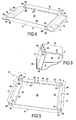
Un élément d'emballage conforme à l'invention tel qu'illustré à la
L'élément d'emballage 1 est obtenu à partir d'un flan prédécoupé 2 tel qu'illustré à plat à la
Selon la variante de réalisation considérée, l'élément d'emballage 1 possède une forme générale rectangulaire présentant, dans l'exemple illustré, deux côtés dits longitudinaux opposés 3 et deux côtés dits transversaux opposés 4 s'étendant perpendiculairement aux côtés longitudinaux 3. According to the variant embodiment considered, the packaging element 1 has a generally rectangular shape having, in the example shown, two so-called longitudinal
Tel que cela ressort plus précisément de la
Au moins l'un, et dans l'exemple illustré, les quatre panneaux de côté 6, 7, 10 et 11 sont prolongés chacun par un panneau de retour respectivement 15, 16, 17 et 18 qui est relié au panneau de côté qui le borde, par une ligne de pliage respectivement 20, 21, 22, 23. Ainsi, les lignes de pliage 20 et 21 des panneaux de retour 15, 16 des côtés longitudinaux 3 sont parallèles entre elles et parallèles aux lignes de pliage 8 et 9, tandis que les lignes de pliage 22 et 23 des panneaux de retour 17, 18 des côtés transversaux 4 sont parallèles entre elles et parallèles aux lignes de pliage 13 et 14. At least one, and in the example shown, the four
Selon une caractéristique de l'objet de l'invention, au moins l'un, à savoir le panneau de retour 16 dans l'exemple illustré, est solidaire d'un contre-panneau 30 destiné à être fixé après pliage, contre le panneau de fond 5. Le contre-panneau 30 prolonge le panneau de retour 16 auquel il est attaché, par une zone 31 de liaison fragilisée essentiellement par des découpes. Dans l'exemple illustré, la zone de liaison 31 comporte une série de découpes rectangulaires 32 permettant d'enlever de la matière afin de laisser subsister entre elles des zones ou des ponts de liaison 33 entre le contre-panneau 30 et le panneau de retour 16. Dans l'exemple illustré, la zone de liaison 31 comporte cinq ponts 33 répartis le long du panneau de retour 16 en s'étendant selon une direction sensiblement perpendiculaire à la ligne de pliage 21. Les ponts de liaison 33 présentent une largeur limitée adaptée pour permettre la tenue mécanique entre le contre-panneau 30 et le panneau de liaison 16. Il ressort de la variante illustrée que la hauteur cumulée des ponts de liaison 33 présente une hauteur inférieure à la demi-hauteur du panneau de retour 16. Le contre-panneau 30 est destiné à être fixé sur le panneau de fond 5 en étant plié le long d'une ligne de pliage 35 parallèle aux lignes de pliage 9 et 21 et qui passe par la zone de liaison fragilisée 31. En d'autres termes, la ligne de pliage 35 est aménagée sur chacun des ponts de liaison 33 selon une direction commune parallèle aux lignes de pliage 9 et 21. Selon une caractéristique de l'invention qui sera mieux comprise dans la suite de la description, la distance entre les lignes de pliage 9 et 21 est égale à la distance entre les lignes de pliage 21 et 35. According to a feature of the subject of the invention, at least one, namely the
Selon une variante de réalisation, le contre-panneau 30 possède, selon sa ligne de pliage, une hauteur h inférieure à la hauteur du panneau de fond 5, qui est délimitée entre les lignes de pliage 13 et 14 des côtés transversaux 4. La différence de hauteur entre le contre-panneau 30 et le panneau de fond 5 permet de laisser subsister une zone de montage pour un panneau de contre-fixation 40, 41 prolongeant respectivement un panneau de retour 17 et 18 des côtés transversaux 4. Ainsi, chaque panneau de retour 17 et 18 des côtés transversaux est relié à un panneau de contre-fixation respectivement 40 et 41 par une ligne de pliage respectivement 42 et 43 parallèles aux lignes de pliage 22 et 23.According to an alternative embodiment, the
Selon une caractéristique préférée de réalisation, chaque ligne de pliage 42 et 43 séparant un panneau de retour 17,18 et un panneau de contre-fixation 40 et 41 est pourvu de découpes 44. According to a preferred embodiment, each
Selon une variante de réalisation, les panneaux de côté 6, 7, 10, 11 sont reliés entre eux au niveau de chaque coin, par une paire de volets 50 et 51 reliés entre eux par une ligne de pliage 53 permettant de conférer à chacun d'eux, une forme générale triangulaire. Chaque panneau de côté 6, 7 des côtés longitudinaux 3 se trouve ainsi prolongé de part et d'autre, au-delà des lignes de pliage 13,14 par un volet 51, tandis que chaque panneau de côté 10,11 des côtés transversaux 4 se trouve prolongé de part et d'autre, au-delà des lignes de pliage 8, 9, par un volet 50 qui est relié au volet 51 par la ligne de pliage 53 qui s'étend à partir de chaque coin du panneau de fond 5.According to an alternative embodiment, the
Ces deux volets 50 et 51 sont destinés à être rabattus l'un contre l'autre le long de leur ligne de pliage 53 dirigée vers le panneau de fond 5, de manière à constituer une sorte de soufflet rentrant adapté pour être inséré entre un panneau de côté 10 et 11 des côtés transversaux et un panneau de retour 17 et 18 des côtés transversaux 4. These two
Selon une autre caractéristique de l'objet de l'invention, chaque panneau de retour 17 et 18 des côtés transversaux 4 comporte, de part et d'autre, une patte de blocage 55 s'étendant en saillie par rapport aux lignes de pliage 8 et 9. Selon l'exemple illustré, chaque patte de blocage 55 présente une forme triangulaire de forme complémentaire d'un dégagement ou d'une découpe 57 aménagée sur les panneaux de retour 15 et 16 des côtés longitudinaux. Ainsi, chaque panneau de retour 15, 16 des côtés longitudinaux 3 possède de part et d'autre et en deçà des lignes de pliage 13, 14, une découpe 57. According to another characteristic of the subject of the invention, each
La mise en forme de l'élément d'emballage 1 à partir du flan 2 décrit ci-dessous découle directement de la description qui précède.The shaping of the packaging element 1 from the blank 2 described below follows directly from the foregoing description.
Le contre-panneau 30 est destiné à être fixé par collage sur le panneau de fond 5. A cet effet, et tel que cela ressort de la
Le maintien en position relevée des panneaux des côtés longitudinaux 3 est assuré par le relèvement des côtés transversaux 4. A cet effet, les volets de liaison 50 et 51 sont pliés l'un contre l'autre pour être rentrés ou insérés entre, d'une part, les panneaux de côté 10, 11, des côtés transversaux, pliés respectivement selon les lignes 13 et 14, et, d'autre part, les panneaux de retour 17 et 18 rabattus contre les panneaux de côté 10 et 11 respectivement, pliés le long de leurs lignes de pliage, respectivement 22 et 23. Ainsi, chaque panneau de retour 17 et 18 recouvre les deux paires de volets de liaison 50 et 51 en position repliée. L'assemblage définitif est assuré par l'engagement des pattes de blocage 55, dans les dégagements 57 des panneaux de retour et la mise en appui du panneau de contre-fixation 40,41 contre le panneau de fond 5. Chaque panneau de contre-fixation 40, 41 se retrouve donc en appui contre le bord du contre-panneau 30. Ces panneaux de contre-fixation 40 et 41 sont maintenus en appui contre le contre-panneau 30 par l'intermédiaire des volets de liaison 50, 51 exerçant un effet de rappel comparable à un ressort. Cet appui est maintenu tout en conservant, grâce aux découpes 44, un placage convenable des panneaux de retour 17, 18 contre, respectivement, les panneaux de côté 10, 11. Keeping the panels of the
Dans l'exemple de réalisation décrit ci-dessus, la zone de liaison 31 entre le contre-panneau 30 et le panneau de fond 5 est fragilisée par des découpes ayant permis d'enlever de la matière. Bien entendu, il peut être envisagé de fragiliser la zone de liaison 31 par une série de découpes réalisées par exemple perpendiculairement à la ligne de pliage 35 pour constituer des lignes de scarification ou de diminution de matière.In the embodiment described above, the
Claims (9)
Applications Claiming Priority (1)
| Application Number | Priority Date | Filing Date | Title |
|---|---|---|---|
| FR0759950A FR2925024B1 (en) | 2007-12-18 | 2007-12-18 | FLAN PREDECOUPE FOR REALIZING A REINFORCED BACKGROUND PACKING ELEMENT |
Publications (2)
| Publication Number | Publication Date |
|---|---|
| EP2072408A1 true EP2072408A1 (en) | 2009-06-24 |
| EP2072408B1 EP2072408B1 (en) | 2011-06-29 |
Family
ID=39284234
Family Applications (1)
| Application Number | Title | Priority Date | Filing Date |
|---|---|---|---|
| EP20080171850 Active EP2072408B1 (en) | 2007-12-18 | 2008-12-16 | Blank for making a packaging element with reinforced bottom |
Country Status (3)
| Country | Link |
|---|---|
| EP (1) | EP2072408B1 (en) |
| ES (1) | ES2367404T3 (en) |
| FR (1) | FR2925024B1 (en) |
Cited By (4)
| Publication number | Priority date | Publication date | Assignee | Title |
|---|---|---|---|---|
| WO2013169347A1 (en) * | 2012-05-08 | 2013-11-14 | Multi Packaging Solutions, Inc. | Blanks for containers, and containers, boxes, and methods thereof |
| US9120592B2 (en) | 2012-04-13 | 2015-09-01 | Multi Packaging Solutions, Inc. | Tray cover, tray insert, and methods thereof |
| US10239653B2 (en) | 2014-12-09 | 2019-03-26 | Multi Packaging Solutions, Inc. | Flat foldable packaging |
| DE202020106223U1 (en) | 2020-10-30 | 2022-02-01 | Ar Packaging Gmbh | Folding box comprising a cardboard tray |
Citations (4)
| Publication number | Priority date | Publication date | Assignee | Title |
|---|---|---|---|---|
| EP0442552A1 (en) * | 1990-01-22 | 1991-08-21 | Trimbach Verpakking B.V. | Ready-to-use box with doubled bottom |
| FR2876665A1 (en) * | 2004-10-19 | 2006-04-21 | Sauberlin & Pfeiffer Sa | Cover for packaging case, has folding lines being curved for imparting concave or convex shape to back face when side panels are folded for forming peripheral enclosure with polygon base |
| WO2006097683A1 (en) * | 2005-03-12 | 2006-09-21 | Concept Packaging Services Limited | Improvements in and relating to padded boxes |
| US20070102496A1 (en) * | 2005-11-07 | 2007-05-10 | Kraftool Mfg. (Shanghai) Co., Ltd. | Packing box |
-
2007
- 2007-12-18 FR FR0759950A patent/FR2925024B1/en not_active Expired - Fee Related
-
2008
- 2008-12-16 ES ES08171850T patent/ES2367404T3/en active Active
- 2008-12-16 EP EP20080171850 patent/EP2072408B1/en active Active
Patent Citations (4)
| Publication number | Priority date | Publication date | Assignee | Title |
|---|---|---|---|---|
| EP0442552A1 (en) * | 1990-01-22 | 1991-08-21 | Trimbach Verpakking B.V. | Ready-to-use box with doubled bottom |
| FR2876665A1 (en) * | 2004-10-19 | 2006-04-21 | Sauberlin & Pfeiffer Sa | Cover for packaging case, has folding lines being curved for imparting concave or convex shape to back face when side panels are folded for forming peripheral enclosure with polygon base |
| WO2006097683A1 (en) * | 2005-03-12 | 2006-09-21 | Concept Packaging Services Limited | Improvements in and relating to padded boxes |
| US20070102496A1 (en) * | 2005-11-07 | 2007-05-10 | Kraftool Mfg. (Shanghai) Co., Ltd. | Packing box |
Cited By (9)
| Publication number | Priority date | Publication date | Assignee | Title |
|---|---|---|---|---|
| US9120592B2 (en) | 2012-04-13 | 2015-09-01 | Multi Packaging Solutions, Inc. | Tray cover, tray insert, and methods thereof |
| US9957079B2 (en) | 2012-04-13 | 2018-05-01 | Multi Packaging Solutions, Inc. | Tray cover, tray insert, and methods thereof |
| US10252831B2 (en) | 2012-04-13 | 2019-04-09 | Multi Packaging Solutions, Inc. | Tray cover, tray insert, and methods thereof |
| WO2013169347A1 (en) * | 2012-05-08 | 2013-11-14 | Multi Packaging Solutions, Inc. | Blanks for containers, and containers, boxes, and methods thereof |
| US9409670B2 (en) | 2012-05-08 | 2016-08-09 | Multi Packaging Solutions | Blanks for containers, and containers, boxes, and methods thereof |
| EP3301035A1 (en) * | 2012-05-08 | 2018-04-04 | Multi Packaging Solutions, Inc. | Die cut preform for a container and method of making a container |
| US10239653B2 (en) | 2014-12-09 | 2019-03-26 | Multi Packaging Solutions, Inc. | Flat foldable packaging |
| DE202020106223U1 (en) | 2020-10-30 | 2022-02-01 | Ar Packaging Gmbh | Folding box comprising a cardboard tray |
| EP3992097A1 (en) | 2020-10-30 | 2022-05-04 | AR Packaging GmbH | Folding box comprising a cardboard tray |
Also Published As
| Publication number | Publication date |
|---|---|
| EP2072408B1 (en) | 2011-06-29 |
| ES2367404T3 (en) | 2011-11-03 |
| FR2925024A1 (en) | 2009-06-19 |
| FR2925024B1 (en) | 2012-10-12 |
Similar Documents
| Publication | Publication Date | Title |
|---|---|---|
| EP2197752B1 (en) | Set of blanks, box and box production method | |
| EP2225162B1 (en) | Packing case with centring tab, set of cutouts and method for creating such a case | |
| EP3061696B1 (en) | Blank for forming a packaging of at least one windscreen wiper, packaging and method of producing such a packaging | |
| EP2072408B1 (en) | Blank for making a packaging element with reinforced bottom | |
| EP0567413B1 (en) | Polygonal package made from sheet material and blank for making such package | |
| FR2609965A1 (en) | Package of the box type, in particular a vegetable box made of cardboard, corrugated cardboard or other sheet material | |
| FR2905937A1 (en) | Tray for transporting and displaying e.g. fruit, has long and short lateral walls extending from sides of rectangular shaped bottom wall, and main rigidifying rib of bottom wall extending along internal surface of bottom wall | |
| EP0785138B1 (en) | Blanks assembly for packing case in the form of a display and case obtained from such assembly | |
| FR2861370A1 (en) | Packaging case for use in bakery, has lateral branches and thumb tab that are delimited by two recesses so as to allow tab to move from branches by deformation and overlap opposite wall | |
| FR2883847A1 (en) | Cardboard pallet for transporting e.g. heavy object, has plate including two integrated tabs cut in corrugated cardboard, where tabs cooperate with notches arranged along edges between girdle and bottom of package to lock package on plate | |
| EP1803651B1 (en) | Securing element for suspension of an object and packaging comprising such an element | |
| FR2588505A1 (en) | METHOD FOR THE TWO-WALL OR TWO-SIDED ASSEMBLY OF A PACKAGE MADE FROM A SINGLE FLAN OR MULTIPLE FLANS OF CARDBOARD AND THE PACKAGE PRODUCED THEREBY | |
| EP1771341B1 (en) | Octagonal veneer tray | |
| FR2659062A1 (en) | Package for packaging products, food products in particular, and method of assembly of such a package | |
| FR2666300A1 (en) | Package made of cardboard, corrugated cardboard or other sheet material, and blank suitable for making such a package | |
| FR2742730A1 (en) | Packaging case formed from pre-cut blank | |
| FR2876665A1 (en) | Cover for packaging case, has folding lines being curved for imparting concave or convex shape to back face when side panels are folded for forming peripheral enclosure with polygon base | |
| FR3040980A1 (en) | FLAT PRECURSOR FOR PACKAGING, METHOD AND PACKAGING | |
| FR3017604A1 (en) | PACKAGE OF CONDITIONING WITH REINFORCEMENT FRAME IN ANGLES | |
| FR2561580A1 (en) | Method for forming a separator made of cardboard, corrugated cardboard or other sheet material, suitable for packaging any articles in cells, and corresponding blank, package or separator | |
| FR2622538A1 (en) | Package with lateral flaps | |
| FR3132700A3 (en) | Collapsible transport box with reinforced bottom | |
| FR2583719A1 (en) | Support frame for cellular tray, blank capable of producing such a support frame, and package with cellular tray or trays using this frame, particularly for the packaging of fruit. | |
| FR2773780A1 (en) | Corrugated cardboard packaging tray for fruit and vegetables | |
| FR2729641A1 (en) | Reinforcement for undersides of cardboard cartons |
Legal Events
| Date | Code | Title | Description |
|---|---|---|---|
| PUAI | Public reference made under article 153(3) epc to a published international application that has entered the european phase |
Free format text: ORIGINAL CODE: 0009012 |
|
| AK | Designated contracting states |
Kind code of ref document: A1 Designated state(s): AT BE BG CH CY CZ DE DK EE ES FI FR GB GR HR HU IE IS IT LI LT LU LV MC MT NL NO PL PT RO SE SI SK TR |
|
| AX | Request for extension of the european patent |
Extension state: AL BA MK RS |
|
| 17P | Request for examination filed |
Effective date: 20091204 |
|
| 17Q | First examination report despatched |
Effective date: 20100105 |
|
| AKX | Designation fees paid |
Designated state(s): BE CH DE ES FR IT LI |
|
| RTI1 | Title (correction) |
Free format text: BLANK FOR MAKING A PACKAGING ELEMENT WITH REINFORCED BOTTOM |
|
| GRAP | Despatch of communication of intention to grant a patent |
Free format text: ORIGINAL CODE: EPIDOSNIGR1 |
|
| GRAS | Grant fee paid |
Free format text: ORIGINAL CODE: EPIDOSNIGR3 |
|
| GRAA | (expected) grant |
Free format text: ORIGINAL CODE: 0009210 |
|
| AK | Designated contracting states |
Kind code of ref document: B1 Designated state(s): BE CH DE ES FR IT LI |
|
| REG | Reference to a national code |
Ref country code: CH Ref legal event code: EP |
|
| REG | Reference to a national code |
Ref country code: DE Ref legal event code: R096 Ref document number: 602008007922 Country of ref document: DE Effective date: 20110818 |
|
| REG | Reference to a national code |
Ref country code: CH Ref legal event code: NV Representative=s name: BOVARD AG |
|
| REG | Reference to a national code |
Ref country code: ES Ref legal event code: FG2A Ref document number: 2367404 Country of ref document: ES Kind code of ref document: T3 Effective date: 20111103 |
|
| PLBE | No opposition filed within time limit |
Free format text: ORIGINAL CODE: 0009261 |
|
| STAA | Information on the status of an ep patent application or granted ep patent |
Free format text: STATUS: NO OPPOSITION FILED WITHIN TIME LIMIT |
|
| 26N | No opposition filed |
Effective date: 20120330 |
|
| REG | Reference to a national code |
Ref country code: DE Ref legal event code: R097 Ref document number: 602008007922 Country of ref document: DE Effective date: 20120330 |
|
| REG | Reference to a national code |
Ref country code: FR Ref legal event code: PLFP Year of fee payment: 8 |
|
| REG | Reference to a national code |
Ref country code: FR Ref legal event code: PLFP Year of fee payment: 9 |
|
| REG | Reference to a national code |
Ref country code: FR Ref legal event code: PLFP Year of fee payment: 10 |
|
| PGFP | Annual fee paid to national office [announced via postgrant information from national office to epo] |
Ref country code: BE Payment date: 20221213 Year of fee payment: 15 |
|
| REG | Reference to a national code |
Ref country code: DE Ref legal event code: R082 Ref document number: 602008007922 Country of ref document: DE Representative=s name: CBDL PATENTANWAELTE GBR, DE |
|
| PGFP | Annual fee paid to national office [announced via postgrant information from national office to epo] |
Ref country code: ES Payment date: 20230105 Year of fee payment: 15 Ref country code: CH Payment date: 20221229 Year of fee payment: 15 |
|
| PGFP | Annual fee paid to national office [announced via postgrant information from national office to epo] |
Ref country code: FR Payment date: 20230919 Year of fee payment: 16 |
|
| PGFP | Annual fee paid to national office [announced via postgrant information from national office to epo] |
Ref country code: IT Payment date: 20231212 Year of fee payment: 16 Ref country code: DE Payment date: 20231208 Year of fee payment: 16 |
|
| PGFP | Annual fee paid to national office [announced via postgrant information from national office to epo] |
Ref country code: BE Payment date: 20231212 Year of fee payment: 16 |
|
| PGFP | Annual fee paid to national office [announced via postgrant information from national office to epo] |
Ref country code: ES Payment date: 20240108 Year of fee payment: 16 |