EP2072189A1 - Brennkraftbetriebenes Setzgerät - Google Patents
Brennkraftbetriebenes Setzgerät Download PDFInfo
- Publication number
- EP2072189A1 EP2072189A1 EP08105935A EP08105935A EP2072189A1 EP 2072189 A1 EP2072189 A1 EP 2072189A1 EP 08105935 A EP08105935 A EP 08105935A EP 08105935 A EP08105935 A EP 08105935A EP 2072189 A1 EP2072189 A1 EP 2072189A1
- Authority
- EP
- European Patent Office
- Prior art keywords
- damping element
- motor
- annular
- setting tool
- annular recess
- Prior art date
- Legal status (The legal status is an assumption and is not a legal conclusion. Google has not performed a legal analysis and makes no representation as to the accuracy of the status listed.)
- Granted
Links
Images


Classifications
-
- B—PERFORMING OPERATIONS; TRANSPORTING
- B25—HAND TOOLS; PORTABLE POWER-DRIVEN TOOLS; MANIPULATORS
- B25C—HAND-HELD NAILING OR STAPLING TOOLS; MANUALLY OPERATED PORTABLE STAPLING TOOLS
- B25C1/00—Hand-held nailing tools; Nail feeding devices
- B25C1/08—Hand-held nailing tools; Nail feeding devices operated by combustion pressure
-
- B—PERFORMING OPERATIONS; TRANSPORTING
- B25—HAND TOOLS; PORTABLE POWER-DRIVEN TOOLS; MANIPULATORS
- B25F—COMBINATION OR MULTI-PURPOSE TOOLS NOT OTHERWISE PROVIDED FOR; DETAILS OR COMPONENTS OF PORTABLE POWER-DRIVEN TOOLS NOT PARTICULARLY RELATED TO THE OPERATIONS PERFORMED AND NOT OTHERWISE PROVIDED FOR
- B25F5/00—Details or components of portable power-driven tools not particularly related to the operations performed and not otherwise provided for
- B25F5/006—Vibration damping means
Definitions
- the present invention relates to a combustion-powered setting tool, the type mentioned in the preamble of claim 1.
- Such setting devices can, for. B. be operated with gaseous or vaporizable liquid fuels.
- a setting piston is driven by expanding combustion gases during a setting process. About this setting piston fasteners can then be driven into a background.
- the fuel is mixed via a fan or fan located in the combustion chamber with the air in the combustion chamber.
- the fan is driven by a motor, preferably an electric motor.
- the forces occurring during a setting process lead to high accelerations of the setting tool. Even in case of incorrect applications, when the energy of the setting piston has to be completely absorbed by the setting tool, large accelerations occur. These accelerations have a negative effect on the life of the fan motor.
- WO 2006/106866 is a generic combustion-powered setting tool with a combustion chamber and a fan arranged in the combustion chamber known.
- the fan is drivable via a motor, which is arranged in a receptacle in a rear combustion chamber wall. Between the two axial ends of the motor and the opposite wall portions of the receptacle there are arranged annular damping elements which dampen movements of the motor along its longitudinal axis.
- the object of the present invention is to provide a combustion-powered setting tool of the aforementioned type, in which a vibration of the engine via the damping system is reduced to a minimum.
- annular recess is arranged on the circumference of the annular damping element.
- the force characteristic of a damping element formed in this way exhibits an advantageously pronounced hysteresis. Due to this hysteresis and a friction on the inner surfaces of the annular recess in the compressed state of the damping element, the energy stored by the deformation thereof is only partially converted back into work. The unreacted portion is dissipated in the damping element. An excited oscillation thus comes to a standstill faster than with a damping element without circumferential annular recess. The attenuated via the damping element according to the invention thus comes again faster in its rest position, whereby its life is increased.
- the term “annular” is understood to mean not only round and elliptical ring shapes but also polygonal ring shapes.
- annular recess is arranged on the inner circumference of the annular damping element, whereby an optimal deformation behavior of the damping element is achieved.
- An optimal design of the damping element is achieved when a cross-sectional area of the annular recess accounts for 20% to 60%, preferably 25% to 50%, of a total cross-sectional area of the damping element.
- the annular recess has a U-shaped cross-section, whereby a collapsing of the damping element always creates a closed interior can be caught in the air, which has an advantageous effect on the damping properties of the damping element.
- the U-legs do not necessarily have a straight line in cross-section, but they can also be curved or outwards (with respect to the interior) bent.
- annular circumferential projection is arranged, which forms a sealing lip via which a seal against the adjacent wall portion or the engine.
- the encircling projection forms, when the annular recess is arranged on the inner circumference of the annular damping element, a fulcrum, which imposes a directional movement on the damping element during an upsetting operation and thereby supports a closure of the annular recess.
- a projection or such a sealing lip could also be additionally provided on the second end face opposite the first end side of the damping element.
- the diameter of the annular projection or the sealing lip is smaller than the radial depth or as the outer diameter of the annular recess.
- This flange portion advantageously serves as a centering support of the damping element with respect to a wall of the motor supporting element which surrounds the damping element and thereby ensures the necessary free space which the damping element requires in an upsetting operation.
- the motor is supported on both axial end regions via a respective damping element in the receptacle, whereby an optimal damping of the motor is achieved.
- the first end face of the damping elements, on which the annular projection (or the sealing lip) is arranged faces the axial end region of the motor, so that sealing takes place at least in relation to the motor.
- the setting tool 10 has a one-piece or multi-part housing, generally designated 11, in which a drive 12 is arranged. About the drive 12, a fastener, such as a nail, bolts, etc. are driven into a workpiece.
- the fasteners may, for. B. be stored in a magazine on setting tool 10.
- the drive includes, inter alia, a combustion chamber 15 and a guide cylinder 13, in which a setting piston 14 is arranged axially displaceable.
- a trigger switch 19 is arranged on a handle 18 of the setting device 10, via which a in Fig. 1 non-visible ignition device in the combustion chamber 15, such.
- a spark plug can be triggered when the setting tool 10 has been pressed against a workpiece.
- trigger switch 19 can still further switches, such.
- As pressure switch, combustion chamber switch or magazine switch may be provided.
- the setting device 10 can be operated with a fuel gas or with a vaporizable liquid fuel, which in an in FIG. 1 Not shown fuel reservoir, such. B. a fuel can, is provided.
- a arranged in the combustion chamber 15 and driven by a motor 17 fan 16 serves both to produce a turbulent flow regime of one in the closed combustion chamber 15 located oxidant-fuel mixture and the rinsing of the open combustion chamber 15 with fresh air after the setting process.
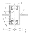
- the motor 17 is mounted in a receptacle 20 of a motor support member 21, which in the FIG. 2 apparent embodiment in one piece with a combustion chamber rear wall 26 (in Fig. 2 only partially shown) is formed.
- the combustion chamber rear wall 26 can act as a closure for an axially displaceable combustion chamber sleeve.
- the motor 17 is supported at its first axial end region 24 and its second axial end region 25 in each case via an annular damping element 30 to the first and second wall sections 22, 23 delimiting the receptacle 20.
- the term "axial" refers to the axis A defined by the longitudinal extent of the motor 17, to which the annular damping elements 30 are also arranged substantially coaxially.
- the damping elements 30 have radially inside a continuously encircling annular recess 33 which is U-shaped in cross-section, wherein the radial depth T of the annular recess is smaller than its axial width B.
- the cross-sectional area of the annular recess 33 is approx 20% to 60%, preferably 25% to 50%, of the total cross-sectional area of the damping element 30.
- At first axial end faces 31 of the damping elements 30, which face the motor 17 in both damping elements 30, is directly adjacent to the ring openings 35 of FIG Damping elements 30 each arranged as a sealing lip annular circumferential projection 34 which projects beyond the respective end face 31 in the axial direction.
- a radially outer peripheral flange portion 32 is arranged at both damping elements 30, through which the support surface of the damping elements 30 on the first wall portion 22 and on the second wall portion 23 is increased.
- the annular recess could also be arranged on the outer circumference of the damping elements, wherein the annular projection would then preferably be arranged radially outward on the first axial end face (not shown in the figures).
- the motor 17 thus sits between the two damping elements 30 in the receptacle 20, wherein the two damping elements 30 abut on the one hand with their annular projections 34 on the motor 17 and on the other hand with their over the flange 32 enlarged axial end of the wall portions 22, 23 abut.
- the second wall section 23 is formed via a cover part or closure means for the receptacle 20, while the first wall section 22 is formed integrally with the motor support element 21.
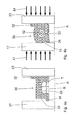
- Fig. 4a is the damping element 30 in its initial position in which it has no deformation.
- Fig. 4b is the damping element 30 after the triggering of a setting operation in a loading phase in which the damping element 30 between the motor 17 and the second wall portion 23 via the forces acting on these (shown by the first arrows 41) is compressed.
- the interior of the annular recess 33 communicates only through a narrow annular gap with the environment.
- an overpressure P represented by the second arrows 42
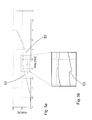
- FIGS. 4a to 4d described mode of action of the damping elements 30 show their power characteristics advantageously a pronounced hysteresis, such as FIGS. 5a and 5b can be clearly seen.
- the stored by the damping elements 30 due to their deformation energy is, due to the hysteresis and the friction on the inner surfaces of the annular recess, only partially converted back into work. The unreacted portion is dissipated in the damping element 30.
- FIG. 3 illustrated embodiment of an inventive setting device differs only from the previously shown that the motor support member 21 is formed as a separate sleeve which is fixed in a corresponding recess 26 of a combustion chamber rear wall. Because of the further technical details of this embodiment is fully to the preceding description of the Figures 1 to 5b directed.
Landscapes
- Engineering & Computer Science (AREA)
- Mechanical Engineering (AREA)
- Chemical & Material Sciences (AREA)
- Combustion & Propulsion (AREA)
- Portable Nailing Machines And Staplers (AREA)
Abstract
Description
- Die vorliegende Erfindung betrifft ein brennkraftbetriebenes Setzgerät, der im Oberbegriff des Patentanspruchs 1 genannten Art.
- Derartige Setzgeräte können z. B. mit gasförmigen oder verdampfbaren flüssigen Brennstoffen betrieben werden. Bei den brennkraftbetriebenen Setzgeräten wird bei einem Setzvorgang ein Setzkolben über expandierende Verbrennungsgase angetrieben. Über diesen Setzkolben können dann Befestigungselemente in einen Untergrund eingetrieben werden. Vor einem Verbrennungsvorgang wird der Brennstoff über einen im Brennraum befindlichen Lüfter bzw. Ventilator mit der im Brennraum befindlichen Luft vermischt. Der Lüfter ist dabei über einen Motor, vorzugsweise einen Elektromotor angetrieben. Die während eines Setzvorgangs auftretenden Kräfte führen zu hohen Beschleunigungen des Setzgerätes. Auch bei Fehlanwendungen, wenn die Energie des Setzkolbens komplett vom Setzgerät aufgenommen werden muss, treten grosse Beschleunigungen auf. Diese Beschleunigungen wirken sich negativ auf die Lebensdauer des Lüfter-Motors aus.
- Aus der
WO 2006/106866 ist ein gattungsgemässes brennkraftbetriebenes Setzgerät mit einer Brennkammer und einem in der Brennkammer angeordneten Ventilator bekannt. Der Ventilator ist über einen Motor antreibbar, der in einer Aufnahme in einer rückwärtigen Brennkammerwand angeordnet ist. Zwischen den beiden axialen Enden des Motors und den diesen gegenüberliegenden Wandabschnitten der Aufnahme sind ringförmige Dämpfungselemente angeordnet, die Bewegungen des Motors entlang seiner Längsachse dämpfen. - Die aus der
WO 2006/106866 bekannten Dämpfungskörper dämpfen zwar auftretende Belastungsspitzen, ist das Dämpfungssystem aber einmal angeregt und in Schwingung versetzt, dauert es eine relativ lange Zeit bis das System wieder in Ruhe ist. Ein derartiges Nachschwingen des Motor-Dämpfungssystems bedeutet eine erhöhte Wechselbeanspruchung für den Motor, die dessen Lebensdauer reduziert. - Die Aufgabe der vorliegenden Erfindung liegt darin, ein brennkraftbetriebenes Setzgerät der vorgenannten Art bereitzustellen, bei dem ein Schwingen des Motors über das Dämpfungssystem auf ein Minimum reduziert ist.
- Diese Aufgabe wird durch ein brennkraftbetriebenes Setzgerät nach Anspruch 1 gelöst. Demnach ist am Umfang des ringförmigen Dämpfungselements eine ringförmige Ausnehmung angeordnet. Die Kraftkennlinie eines derart ausgebildeten Dämpfungselements zeigt eine vorteilhaft ausgeprägte Hysterese. Auf Grund dieser Hysterese und einer Reibung an den Innenflächen der ringförmigen Ausnehmung im zusammengedrückten Zustand des Dämpfungselements wird die durch deren Verformung gespeicherte Energie nur zum Teil wieder in Arbeit umgesetzt. Der nicht wieder umgesetzte Anteil wird im Dämpfungselement dissipiert. Eine angeregte Schwingung kommt somit schneller zum Stillstand als bei einem Dämpfungselement ohne umfängliche ringförmige Ausnehmung. Der über das erfindungsgemässe Dämpfungselement gedämpfte Motor kommt somit wieder rascher in seine Ruheposition, wodurch seine Lebensdauer erhöht wird. Unter dem Begriff "ringförmig" werden dabei nicht nur runde und elliptische Ringformen sondern auch polygonale Ringformen verstanden.
- Von Vorteil ist es dabei, wenn die ringförmige Ausnehmung am inneren Umfang des ringförmigen Dämpfungselements angeordnet ist, wodurch ein optimales Deformationsverhalten des Dämpfelements erzielt wird.
- Eine optimale Auslegung des Dämpfungselements wird erzielt, wenn eine Querschnittsfläche der ringförmigen Ausnehmung 20 % bis 60 %, vorzugsweise 25 % bis 50 %, einer Gesamt-Querschnittsfläche des Dämpfungselements ausmacht.
- Vorteilhaft weist die ringförmige Ausnehmung einen U-förmigen Querschnitt auf, wodurch bei einem Zusammenstauchen des Dämpfungselements immer ein geschlossener Innenraum entsteht in dem Luft gefangen werden kann, was sich vorteilhaft auf die Dämpfungseigenschaften des Dämpfungselements auswirkt. Die U-Schenkel müssen dabei im Querschnitt nicht unbedingt gradlinig verlaufen, sie können vielmehr auch bauchig bzw. nach aussen (bezogen auf den Innenraum) gebogen verlaufen.
- Günstig ist es ferner, wenn eine radiale Tiefe der ringförmigen Ausnehmung kleiner als eine axiale Breite der ringförmigen Ausnehmung ist, wodurch die Auslegung des Dämpfungselements weiter verbessert ist.
- Vorteilhaft ist wenigstens an einer ersten axialen Stirnseite des Dämpfungselements benachbart zu einer Ringöffnung des Dämpfungselements ein ringförmig umlaufender Vorsprung angeordnet, der eine Dichtlippe bildet über die eine Abdichtung gegenüber dem anliegenden Wandabschnitt oder dem Motor erfolgt. Der umlaufende Vorsprung bildet dabei, wenn die ringförmige Ausnehmung am inneren Umfang des ringförmigen Dämpfungselements angeordnet ist, einen Hebelpunkt, der bei einem Stauchvorgang eine gerichtete Bewegung auf das Dämpfungselement aufprägt und dabei ein Verschliessen der ringförmigen Ausnehmung unterstützt. Ein derartiger Vorsprung bzw. eine derartige Dichtlippe könnte auch noch zusätzlich an der der ersten Stirnseite des Dämpfungselements gegenüberliegenden zweiten Stirnseite vorgesehen sein. Der Durchmesser des ringförmigen Vorsprungs bzw. der Dichtlippe ist dabei kleiner, als die radiale Tiefe bzw. als der äussere Durchmesser der ringförmigen Ausnehmung.
- Von Vorteil ist es ferner, wenn an einem der ersten axialen Stirnseite gegenüberliegenden axialen Ende des Dämpfungselementes ein an dessen äusserem Umfang umlaufender Flanschabschnitt angeordnet ist. Dieser Flanschabschnitt dient vorteilhaft als zentrierende Abstützung des Dämpfungselements gegenüber einer das Dämpfungselement umfangenden Wand des Motortragelements und gewährleistet dabei den notwendigen Freiraum, den das Dämpfungselement bei einem Stauchvorgang benötigt.
- Weiterhin von Vorteil ist es, wenn der Motor an beiden axialen Endbereichen über jeweils ein Dämpfungselement in der Aufnahme abgestützt ist, wodurch eine optimale Dämpfung des Motors erzielt wird.
- Günstig ist es ferner, wenn jeweils die erste Stirnseite der Dämpfungselemente, an welcher der ringförmige Vorsprung (bzw. die Dichtlippe) angeordnet ist, dem axialen Endbereich des Motors zugewandt ist, so dass zumindest gegenüber dem Motor eine Abdichtung erfolgt.
- In den Zeichnungen ist die Erfindung in einem Ausführungsbeispiel dargestellt.
-
- Fig. 1
- ein erfindungsgemässes brennkraftbetriebenes Setzgerät,
- Fig. 2
- ein Detail des Setzgerätes gemäss der Markierung II aus
Fig. 1 , - Fig. 3
- ein Detail eines weiteren Setzgerätes analog zu
Fig. 2 , - Fig. 4a
- ein Schnitt durch ein Dämpfungselement aus
Fig. 2 in entspannter Lage, - Fig. 4b
- das Dämpfungselement gemäss
Fig. 4a während einer Belastungsphase, - Fig. 4c
- das Dämpfungselement gemäss
Fig. 4a in stark gestauchtem Zustand, - Fig. 4d
- das Dämpfungselement gemäss
Fig. 4a während einer Entlastungsphase, - Fig. 5a
- ein Diagramm mit der Kraftkennlinie des erfindungsgemässen Dämpfungselementes aufgetragen über den Stauchweg bei Be- und Entlastung.
- In den
Figuren 1 ,2 und4a bis 4d ist ein erfindungsgemässes handgeführtes brennkraftbetriebenes Setzgerät 10 dargestellt. Das Setzgerät 10 verfügt über ein allgemein mit 11 bezeichnetes ein- oder mehrteiliges Gehäuse, in dem ein Antrieb 12 angeordnet ist. Über den Antrieb 12 kann ein Befestigungselement, wie ein Nagel, Bolzen, etc. in ein Werkstück eingetrieben werden. Die Befestigungselemente können z. B. in einem Magazin am Setzgerät 10 bevorratet sein. - Zum Antrieb gehören u. a. eine Brennkammer 15 und ein Führungszylinder 13, in dem ein Setzkolben 14 axial versetzbar angeordnet ist. Wie aus
Fig. 1 ferner ersichtlich ist, ist an einem Handgriff 18 des Setzgerät 10 ein Auslöseschalter 19 angeordnet, über den eine inFig. 1 nicht sichtbare Zündeinrichtung in der Brennkammer 15, wie z. B. eine Zündkerze, auslösbar ist, wenn das Setzgerät 10 an ein Werkstück angepresst worden ist. Zusätzlich zu dem vorhergehend erwähnten Auslöseschalter 19 können noch weitere Schalter, wie z. B. Anpressschalter, Brennkammerschalter oder Magazinschalter, vorgesehen sein. - Das Setzgerät 10 kann mit einem Brenngas oder mit einem verdampfbaren Flüssigbrennstoff betrieben werden, das in einem in
Figur 1 nicht dargestellten Brennstoffreservoir, wie z. B. einer Brennstoffdose, bereitgestellt wird. - Ein in der Brennkammer 15 angeordneter und über einen Motor 17 antreibbarer Ventilator 16 dient sowohl der Erzeugung eines turbulenten Strömungsregimes eines in der geschlossenen Brennkammer 15 befindlichen Oxidationsmittel-Brennstoffgemisches als auch dem Ausspülen der geöffneten Brennkammer 15 mit Frischluft nach erfolgtem Setzvorgang.
- Zur Versorgung der elektrischen Verbraucher, wie z. B. der Zündeinrichtung und des Motors 17 mit elektrischer Energie ist eine in den Figuren nicht dargestellte elektrische Energiequelle, wie z. B. ein Akkumulator, vorhanden.
- Der Motor 17 ist in einer Aufnahme 20 eines Motortragelementes 21 gelagert, welches in der aus
Figur 2 ersichtlichen Ausführungsform einteilig mit einer Brennkammerrückwand 26 (inFig. 2 nur ausschnittsweise dargestellt) ausgebildet ist. Die Brennkammerrückwand 26 kann dabei als Verschluss für eine axial verschiebbare Brennkammerhülse fungieren. Der Motor 17 stützt sich an seinem ersten axialen Endbereich 24 und seinem zweiten axialen Endbereich 25 jeweils über ein ringförmiges Dämpfungselement 30 an den die Aufnahme 20 begrenzenden ersten und zweiten Wandabschnitten 22, 23 ab. Der Begriff "axial" bezieht sich dabei auf die durch die Längserstreckung des Motors 17 definierte Achse A, zu der auch die ringförmigen Dämpfungselemente 30 im Wesentlichen koaxial angeordnet sind. - Die Dämpfungselemente 30 weisen radial innen eine durchgehend umlaufende ringförmige Ausnehmung 33 auf, die im Querschnitt U-förmig ist, wobei die radiale Tiefe T der ringförmigen Ausnehmung kleiner ist als ihre axiale Breite B. Bei beiden Dämpfungselementen 30 beträgt die Querschnittsfläche der ringförmigen Ausnehmung 33 ca. 20 % bis 60 %, vorzugsweise 25 % bis 50 %, der Gesamt-Querschnittsfläche des Dämpfungselements 30. An ersten axialen Stirnseiten 31 der Dämpfungselemente 30, die bei beiden Dämpfungselementen 30 dem Motor 17 zugewandt sind, ist direkt benachbart zu den Ringöffnungen 35 der Dämpfungselemente 30 jeweils ein als Dichtlippe ausgebildeter ringförmig umlaufender Vorsprung 34 angeordnet, der die jeweilige Stirnseite 31 in axialer Richtung überragt. An einem der ersten axialen Stirnseite 31 gegenüberliegenden axialen Ende des Dämpfungselementes 30 ist bei beiden Dämpfungselementen 30 jeweils ein radial aussen umlaufender Flanschabschnitt 32 angeordnet, durch den die Abstützfläche der Dämpfungselemente 30 am ersten Wandabschnitt 22 bzw. am zweiten Wandabschnitt 23 vergrössert ist. Alternativ könnte die ringförmige Ausnehmung auch am äusseren Umfang der Dämpfungselemente angeordnet sein, wobei der ringförmige Vorsprung dann vorzugsweise radial aussen an der ersten axialen Stirnseite angeordnet wäre (in den Figuren nicht dargestellt).
- Der Motor 17 sitzt also zwischen den beiden Dämpfungselementen 30 in der Aufnahme 20, wobei die beiden Dämpfungselemente 30 einerseits mit ihren ringförmigen Vorsprüngen 34 am Motor 17 anliegen und andererseits mit ihren über die Flanschabschnitte 32 vergrösserten anderen axialen Enden an den Wandabschnitten 22, 23 anliegen. Der zweite Wandabschnitt 23 ist dabei über ein Deckelteil bzw. Verschlussmittel für die Aufnahme 20 gebildet, während der erste Wandabschnitt 22 integral mit dem Motortragelement 21 ausgebildet ist.
- Anhand der
Figuren 4a bis 4d wird nun die Funktion der Dämpfungselemente 30 beispielhaft anhand des zwischen dem Motor 17 und dem zweiten Wandabschnitt 23 angeordneten Dämpfungselementes 30 beschrieben. InFig. 4a befindet sich das Dämpfungselement 30 in seiner Ausgangslage, in der es keine Deformation aufweist. - In
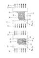
Fig. 4b befindet sich das Dämpfungselement 30 nach dem Auslösen eines Setzvorgangs in einer Belastungsphase, in der das Dämpfungselement 30 zwischen dem Motor 17 und dem zweiten Wandabschnitt 23 über die auf diese wirkenden Kräfte (dargestellt durch die ersten Pfeile 41) gestaucht wird. Der Innenraum der ringförmigen Ausnehmung 33 kommuniziert nur noch durch einen engen Ringspalt mit der Umgebung. In der ringförmigen Ausnehmung 33 baut sich dadurch ein Überdruck P (dargestellt durch die zweiten Pfeile 42) auf. Dieses führt im mittleren Bereich des Stauchweges zu einem stärkeren Kraftanstieg, wie am Verlauf der Belastungs-Kraftkennlinie 51 in denFiguren 5a und 5b zu sehen ist. - In
Fig. 4c wurde das Dämpfungselement 30 über die auf diese wirkenden Kräfte (dargestellt durch die ersten Pfeile 41) stark zusammen gestaucht, wobei die Innenflächen der ringförmigen Ausnehmung 33 sich zumindest partiell aneinander anlegen und die Luft durch den Spalt nach aussen gedrückt wird (siehe dritte Pfeile 43). Dieses führt zu einem geringen Kraftabfall, wie am Verlauf der Belastungs-Kraftkennlinie 51 (zwischen ca. 2,25 mm und 3 mm Weg) in denFiguren 5a und 5b zu sehen ist. Eine weitere Zunahme der Kraft erfolgt bei weiterem Zusammenstauchen des Dämpfungselements 30, wenn die Innenflächen sich nahezu vollständig aneinander anlegen und es auch zu Relativbewegungen der Innenflächen zueinander kommt, welche eine Reibung verursachen. - In
Fig. 4d wird das Dämpfungselement 30 wieder entlastet (dargestellt durch die fünften Pfeile 45) und die stauchende Kraft geht gegen Null. Das Dämpfungselement 30 hat nun das Bestreben wieder in seine Ausgangsform zurückzukehren. Diese Rückstellung wird aber in ihrer Bewegung dadurch gehindert, dass sich nun im Innenraum der ringförmigen Ausnehmung 33 ein Unterdruck P eingestellt hat (siehe vierte Pfeile 44), der der Öffnungskraft entgegenwirkt. Dieser Unterdruck P bleibt solange eingestellt, wie der Innenraum der ringförmigen Ausnehmung 33 abgedichtet bleibt. Ist der Öffnungsprozess so weit fortgeschritten, dass die Funktion der Abdichtung nicht mehr gewährleistet ist, dann kommt es zum Druckausgleich zwischen der Umgebung und dem Innenraum der ringförmigen Ausnehmung 33. Dieser Druckausgleich macht sich bemerkbar durch den ausgeprägten Sprung 53 in der Entlastungs-Kraftkennlinie 52 in denFiguren 5a und 5b . - Durch die zuvor anhand der
Figuren 4a bis 4d beschriebene Wirkungsweise der Dämpfungselemente 30 zeigen deren Kraftkennlinien vorteilhaft eine ausgeprägte Hysterese, wie denFiguren 5a und 5b deutlich zu entnehmen ist. Die durch die Dämpfungselemente 30 aufgrund deren Verformung gespeicherte Energie wird, auf Grund der Hysterese und der Reibung an den Innenflächen der ringförmigen Ausnehmung, nur zum Teil wieder in Arbeit umgesetzt. Der nicht wieder umgesetzte Anteil wird im Dämpfungselement 30 dissipiert. - Die in
Figur 3 dargestellte Ausführungsform eines erfindungsgemässen Setzgeräts unterscheidet sich nur dadurch von der vorhergehend dargestellten, dass das Motortragelement 21 als separate Hülse ausgebildet ist, die in einer entsprechenden Ausnehmung einer Brennkammerrückwand 26 festgelegt ist. Wegen der weiteren technischen Details dieser Ausführungsform wird vollumfänglich auf die vorhergehende Beschreibung zu denFiguren 1 bis 5b verwiesen.
Claims (9)
- Brennkraftbetriebenes Setzgerät (10) zum Eintreiben von Befestigungselementen, mit einer Brennkammer (15) und mit einem über einen Motor (17) betreibbaren Ventilator (16),
wobei der Motor (17) in einer Aufnahme (20) eines Motortragelementes (21) gelagert ist und der Motor (17) sich an wenigstens einem seiner axialen Endbereiche (24, 25) über ein ringförmiges Dämpfungselement (30) an einem die Aufnahme (20) begrenzenden Wandabschnitt (22, 23) abstützt,
dadurch gekennzeichnet, dass am Umfang des ringförmigen Dämpfungselements (30) eine ringförmige Ausnehmung (33) angeordnet ist. - Setzgerät, nach Anspruch 1, dadurch gekennzeichnet, dass die ringförmige Ausnehmung (33) am inneren Umfang des Dämpfungselements (30) angebracht ist.
- Setzgerät, nach Anspruch 1 oder 2, dadurch gekennzeichnet, dass eine Querschnittsfläche der ringförmigen Ausnehmung (33) 20 % bis 60 % einer Gesamt-Querschnittsfläche des Dämpfungselements (30) ausmacht.
- Setzgerät, nach einem der Ansprüche 1 bis 3, dadurch gekennzeichnet, dass die ringförmige Ausnehmung (33) einen U-förmigen Querschnitt aufweist.
- Setzgerät, nach einem der Ansprüche 1 bis 4, dadurch gekennzeichnet, dass eine radiale Tiefe (T) der ringförmigen Ausnehmung (33) kleiner als eine axiale Breite (B) der ringförmige Ausnehmung (33) ist.
- Setzgerät, nach einem der Ansprüche 1 bis 5, dadurch gekennzeichnet, dass wenigstens an einer ersten axialen Stirnseite (31) des Dämpfungselements (30) direkt benachbart zu einer Ringöffnung (35) des Dämpfungselements (30) ein ringförmig umlaufender Vorsprung (34) angeordnet ist.
- Setzgerät, nach einem der Ansprüche 1 bis 6, dadurch gekennzeichnet, dass an einem der ersten axialen Stirnseite (31) gegenüberliegenden axialen Ende des Dämpfungselementes (30) ein an dessen äusserem Umfang umlaufender Flanschabschnitt (32) angeordnet ist.
- Setzgerät, nach einem der Ansprüche 1 bis 7, dadurch gekennzeichnet, dass der Motor (17) an beiden axialen Endbereichen (24, 25) über jeweils ein Dämpfungselement (30) in der Aufnahme (20) abgestützt ist.
- Setzgerät, nach einem der Ansprüche 1 bis 8, dadurch gekennzeichnet, dass jeweils die erste Stirnseite (31) der Dämpfungselemente (30), an welcher der ringförmige Vorsprung (34) angeordnet ist, dem axialen Endbereich (24, 25) des Motors (17) zugewandt ist.
Applications Claiming Priority (1)
| Application Number | Priority Date | Filing Date | Title |
|---|---|---|---|
| DE102007055904A DE102007055904A1 (de) | 2007-12-21 | 2007-12-21 | Brennkraftbetriebenes Setzgerät |
Publications (2)
| Publication Number | Publication Date |
|---|---|
| EP2072189A1 true EP2072189A1 (de) | 2009-06-24 |
| EP2072189B1 EP2072189B1 (de) | 2013-03-06 |
Family
ID=40521757
Family Applications (1)
| Application Number | Title | Priority Date | Filing Date |
|---|---|---|---|
| EP08105935A Not-in-force EP2072189B1 (de) | 2007-12-21 | 2008-12-04 | Brennkraftbetriebenes Setzgerät |
Country Status (5)
| Country | Link |
|---|---|
| US (1) | US7967177B2 (de) |
| EP (1) | EP2072189B1 (de) |
| JP (1) | JP5297176B2 (de) |
| CN (1) | CN101462263B (de) |
| DE (1) | DE102007055904A1 (de) |
Cited By (1)
| Publication number | Priority date | Publication date | Assignee | Title |
|---|---|---|---|---|
| WO2012145738A1 (en) * | 2011-04-21 | 2012-10-26 | Illinois Tool Works Inc. | Combustion powered tool assembly |
Families Citing this family (6)
| Publication number | Priority date | Publication date | Assignee | Title |
|---|---|---|---|---|
| JP5293992B2 (ja) * | 2007-12-28 | 2013-09-18 | 日立工機株式会社 | 燃焼式打込機 |
| TW201034804A (en) * | 2009-03-20 | 2010-10-01 | Basso Ind Corp | Gas gun suspension and shock-absorbing system |
| DE102009041824A1 (de) * | 2009-09-18 | 2011-03-24 | Hilti Aktiengesellschaft | Vorrichtung zur Übertragung von Energie auf ein Befestigungselement |
| DE102009041828A1 (de) * | 2009-09-18 | 2011-03-24 | Hilti Aktiengesellschaft | Vorrichtung zur Übertragung von Energie auf ein Befestigungselement |
| CN103111984B (zh) * | 2012-12-29 | 2015-02-04 | 南京腾亚精工科技有限公司 | 一种射钉枪电机悬挂密封装置 |
| JP7552334B2 (ja) | 2020-12-18 | 2024-09-18 | マックス株式会社 | 打込み工具 |
Citations (4)
| Publication number | Priority date | Publication date | Assignee | Title |
|---|---|---|---|---|
| EP0123716A2 (de) * | 1983-05-02 | 1984-11-07 | Signode Corporation | Verbrennungsgasbetätigtes Befestigungswerkzeug |
| EP1398118A1 (de) * | 2002-09-12 | 2004-03-17 | Illinois Tool Works, Inc. | Aufhängung für einen Ventilatormotor in einem verbrennungskraftgetriebenen Werkzeug |
| WO2006106866A1 (ja) | 2005-04-01 | 2006-10-12 | Max Co., Ltd | ガス燃焼式打込み工具 |
| WO2007058713A1 (en) * | 2005-11-15 | 2007-05-24 | Illinois Tool Works Inc. | One way valve for combustion tool fan motor |
Family Cites Families (8)
| Publication number | Priority date | Publication date | Assignee | Title |
|---|---|---|---|---|
| IN157475B (de) * | 1981-01-22 | 1986-04-05 | Signode Corp | |
| US4403722A (en) * | 1981-01-22 | 1983-09-13 | Signode Corporation | Combustion gas powered fastener driving tool |
| US4721240A (en) * | 1986-07-02 | 1988-01-26 | Senco Products, Inc. | Cam-controlled self-contained internal combustion fastener driving tool |
| DE69005786T2 (de) * | 1989-10-27 | 1994-04-28 | Hitachi Koki Kk | Mit Verbrennungsgas betriebenes Eintreibwerkzeug für Befestigungsmittel. |
| US5197646A (en) * | 1992-03-09 | 1993-03-30 | Illinois Tool Works Inc. | Combustion-powered tool assembly |
| US5680980A (en) * | 1995-11-27 | 1997-10-28 | Illinois Tool Works Inc. | Fuel injection system for combustion-powered tool |
| US5909836A (en) * | 1997-10-31 | 1999-06-08 | Illinois Tool Works Inc. | Combustion powered tool with combustion chamber lockout |
| JP4608974B2 (ja) * | 2004-07-09 | 2011-01-12 | 日立工機株式会社 | 燃焼式釘打機 |
-
2007
- 2007-12-21 DE DE102007055904A patent/DE102007055904A1/de not_active Withdrawn
-
2008
- 2008-12-04 EP EP08105935A patent/EP2072189B1/de not_active Not-in-force
- 2008-12-16 CN CN200810185941.1A patent/CN101462263B/zh not_active Expired - Fee Related
- 2008-12-18 JP JP2008322522A patent/JP5297176B2/ja not_active Expired - Fee Related
- 2008-12-19 US US12/317,277 patent/US7967177B2/en not_active Expired - Fee Related
Patent Citations (5)
| Publication number | Priority date | Publication date | Assignee | Title |
|---|---|---|---|---|
| EP0123716A2 (de) * | 1983-05-02 | 1984-11-07 | Signode Corporation | Verbrennungsgasbetätigtes Befestigungswerkzeug |
| EP1398118A1 (de) * | 2002-09-12 | 2004-03-17 | Illinois Tool Works, Inc. | Aufhängung für einen Ventilatormotor in einem verbrennungskraftgetriebenen Werkzeug |
| WO2006106866A1 (ja) | 2005-04-01 | 2006-10-12 | Max Co., Ltd | ガス燃焼式打込み工具 |
| EP1864759A1 (de) * | 2005-04-01 | 2007-12-12 | Max Co., Ltd. | Verbrennungsgasbetätigtes schlagwerkzeug |
| WO2007058713A1 (en) * | 2005-11-15 | 2007-05-24 | Illinois Tool Works Inc. | One way valve for combustion tool fan motor |
Cited By (1)
| Publication number | Priority date | Publication date | Assignee | Title |
|---|---|---|---|---|
| WO2012145738A1 (en) * | 2011-04-21 | 2012-10-26 | Illinois Tool Works Inc. | Combustion powered tool assembly |
Also Published As
| Publication number | Publication date |
|---|---|
| US20090159635A1 (en) | 2009-06-25 |
| DE102007055904A1 (de) | 2009-06-25 |
| CN101462263B (zh) | 2013-03-13 |
| US7967177B2 (en) | 2011-06-28 |
| EP2072189B1 (de) | 2013-03-06 |
| JP2009148881A (ja) | 2009-07-09 |
| CN101462263A (zh) | 2009-06-24 |
| JP5297176B2 (ja) | 2013-09-25 |
Similar Documents
| Publication | Publication Date | Title |
|---|---|---|
| EP2072189B1 (de) | Brennkraftbetriebenes Setzgerät | |
| DE69719590T2 (de) | Verbrennungsbetriebenes Werkzeug mit Kolbenhalter- und Stabilisierungsanordnung | |
| DE60307525T2 (de) | Gerät zum Eintreiben von Befestigungsmitteln mit Hilfsadapter für die Dosierventilschieberdichtung für den Brennstoffbehälter | |
| DE2229945C2 (de) | Pralldämpfer für Stoßstangen von Kraftfahrzeugen | |
| DE102017217492A1 (de) | Dreiteiliges Pleuel mit verstellbarer Pleuellänge | |
| DE19815650A1 (de) | Drehbohrhammer mit verbessertem pneumatischen Antriebssystem | |
| EP3349945B1 (de) | Brenngasbetriebenes eintreibgerät mit ventilglied | |
| EP3349946B1 (de) | Brenngasbetriebenes eintreibgerät mit aufladung | |
| DE102017123075A1 (de) | Arbeitswerkzeug | |
| EP0267177A1 (de) | Kraftstoffeinspritzdüse | |
| EP1903236B1 (de) | Zentralausrücker für eine hydraulische Kupplungsbetätigung | |
| EP1584422B1 (de) | Verfahren und Einrichtung zur Reduktion von Druckspitzen in einer Handwerkzeugmaschine mit elektropneumatischem Schlagwerk | |
| DE2847136A1 (de) | Sekundaerluft-zufuehrungsring fuer eine zuendkerze | |
| EP3393713A1 (de) | Brenngasbetriebenes eintreibgerät | |
| DE102015211477A1 (de) | Hydrostatischer Kupplungsaktor | |
| DE102016106332A1 (de) | Kompressor mit Energiesparvorrichtung und Verfahren zum Entlasten des Kompressors | |
| EP2304220B1 (de) | Hochdruckpumpe | |
| EP3233381A1 (de) | Eintreibgerät mit verstellbarer brennkammer | |
| DE102006035054B4 (de) | Hydraulischer Dämpfer für eine Fahrzeugbremsanlagen-Kolbenpumpe | |
| EP3393718B1 (de) | Brennkraftbetriebenes setzgerät und verfahren zum betreiben eines derartigen setzgeräts | |
| EP3129189B1 (de) | Handgeführtes und halbstationäres setzgerät | |
| DE2236484C2 (de) | Speicherladeventilanordnung | |
| DE102006059560B4 (de) | Kraftstofffilter eines Kraftfahrzeug-Verbrennungsmotors | |
| DE2536143C2 (de) | Hydraulisches Schlaggerät | |
| DE1237382B (de) | Druckgasbetriebene Kolbenkraftmaschine |
Legal Events
| Date | Code | Title | Description |
|---|---|---|---|
| PUAI | Public reference made under article 153(3) epc to a published international application that has entered the european phase |
Free format text: ORIGINAL CODE: 0009012 |
|
| AK | Designated contracting states |
Kind code of ref document: A1 Designated state(s): AT BE BG CH CY CZ DE DK EE ES FI FR GB GR HR HU IE IS IT LI LT LU LV MC MT NL NO PL PT RO SE SI SK TR |
|
| AX | Request for extension of the european patent |
Extension state: AL BA MK RS |
|
| 17P | Request for examination filed |
Effective date: 20091228 |
|
| AKX | Designation fees paid |
Designated state(s): AT BE BG CH CY CZ DE DK EE ES FI FR GB GR HR HU IE IS IT LI LT LU LV MC MT NL NO PL PT RO SE SI SK TR |
|
| GRAP | Despatch of communication of intention to grant a patent |
Free format text: ORIGINAL CODE: EPIDOSNIGR1 |
|
| GRAS | Grant fee paid |
Free format text: ORIGINAL CODE: EPIDOSNIGR3 |
|
| GRAA | (expected) grant |
Free format text: ORIGINAL CODE: 0009210 |
|
| AK | Designated contracting states |
Kind code of ref document: B1 Designated state(s): AT BE BG CH CY CZ DE DK EE ES FI FR GB GR HR HU IE IS IT LI LT LU LV MC MT NL NO PL PT RO SE SI SK TR |
|
| REG | Reference to a national code |
Ref country code: GB Ref legal event code: FG4D Free format text: NOT ENGLISH |
|
| REG | Reference to a national code |
Ref country code: CH Ref legal event code: EP Ref country code: AT Ref legal event code: REF Ref document number: 599327 Country of ref document: AT Kind code of ref document: T Effective date: 20130315 |
|
| REG | Reference to a national code |
Ref country code: IE Ref legal event code: FG4D Free format text: LANGUAGE OF EP DOCUMENT: GERMAN |
|
| REG | Reference to a national code |
Ref country code: DE Ref legal event code: R096 Ref document number: 502008009399 Country of ref document: DE Effective date: 20130502 |
|
| PG25 | Lapsed in a contracting state [announced via postgrant information from national office to epo] |
Ref country code: NO Free format text: LAPSE BECAUSE OF FAILURE TO SUBMIT A TRANSLATION OF THE DESCRIPTION OR TO PAY THE FEE WITHIN THE PRESCRIBED TIME-LIMIT Effective date: 20130606 Ref country code: SE Free format text: LAPSE BECAUSE OF FAILURE TO SUBMIT A TRANSLATION OF THE DESCRIPTION OR TO PAY THE FEE WITHIN THE PRESCRIBED TIME-LIMIT Effective date: 20130306 Ref country code: LT Free format text: LAPSE BECAUSE OF FAILURE TO SUBMIT A TRANSLATION OF THE DESCRIPTION OR TO PAY THE FEE WITHIN THE PRESCRIBED TIME-LIMIT Effective date: 20130306 Ref country code: BG Free format text: LAPSE BECAUSE OF FAILURE TO SUBMIT A TRANSLATION OF THE DESCRIPTION OR TO PAY THE FEE WITHIN THE PRESCRIBED TIME-LIMIT Effective date: 20130606 Ref country code: ES Free format text: LAPSE BECAUSE OF FAILURE TO SUBMIT A TRANSLATION OF THE DESCRIPTION OR TO PAY THE FEE WITHIN THE PRESCRIBED TIME-LIMIT Effective date: 20130617 |
|
| REG | Reference to a national code |
Ref country code: NL Ref legal event code: VDEP Effective date: 20130306 |
|
| REG | Reference to a national code |
Ref country code: LT Ref legal event code: MG4D |
|
| PG25 | Lapsed in a contracting state [announced via postgrant information from national office to epo] |
Ref country code: FI Free format text: LAPSE BECAUSE OF FAILURE TO SUBMIT A TRANSLATION OF THE DESCRIPTION OR TO PAY THE FEE WITHIN THE PRESCRIBED TIME-LIMIT Effective date: 20130306 Ref country code: SI Free format text: LAPSE BECAUSE OF FAILURE TO SUBMIT A TRANSLATION OF THE DESCRIPTION OR TO PAY THE FEE WITHIN THE PRESCRIBED TIME-LIMIT Effective date: 20130306 Ref country code: GR Free format text: LAPSE BECAUSE OF FAILURE TO SUBMIT A TRANSLATION OF THE DESCRIPTION OR TO PAY THE FEE WITHIN THE PRESCRIBED TIME-LIMIT Effective date: 20130607 Ref country code: LV Free format text: LAPSE BECAUSE OF FAILURE TO SUBMIT A TRANSLATION OF THE DESCRIPTION OR TO PAY THE FEE WITHIN THE PRESCRIBED TIME-LIMIT Effective date: 20130306 |
|
| PG25 | Lapsed in a contracting state [announced via postgrant information from national office to epo] |
Ref country code: HR Free format text: LAPSE BECAUSE OF FAILURE TO SUBMIT A TRANSLATION OF THE DESCRIPTION OR TO PAY THE FEE WITHIN THE PRESCRIBED TIME-LIMIT Effective date: 20130306 |
|
| PG25 | Lapsed in a contracting state [announced via postgrant information from national office to epo] |
Ref country code: CZ Free format text: LAPSE BECAUSE OF FAILURE TO SUBMIT A TRANSLATION OF THE DESCRIPTION OR TO PAY THE FEE WITHIN THE PRESCRIBED TIME-LIMIT Effective date: 20130306 Ref country code: SK Free format text: LAPSE BECAUSE OF FAILURE TO SUBMIT A TRANSLATION OF THE DESCRIPTION OR TO PAY THE FEE WITHIN THE PRESCRIBED TIME-LIMIT Effective date: 20130306 Ref country code: RO Free format text: LAPSE BECAUSE OF FAILURE TO SUBMIT A TRANSLATION OF THE DESCRIPTION OR TO PAY THE FEE WITHIN THE PRESCRIBED TIME-LIMIT Effective date: 20130306 Ref country code: IS Free format text: LAPSE BECAUSE OF FAILURE TO SUBMIT A TRANSLATION OF THE DESCRIPTION OR TO PAY THE FEE WITHIN THE PRESCRIBED TIME-LIMIT Effective date: 20130706 Ref country code: EE Free format text: LAPSE BECAUSE OF FAILURE TO SUBMIT A TRANSLATION OF THE DESCRIPTION OR TO PAY THE FEE WITHIN THE PRESCRIBED TIME-LIMIT Effective date: 20130306 Ref country code: PT Free format text: LAPSE BECAUSE OF FAILURE TO SUBMIT A TRANSLATION OF THE DESCRIPTION OR TO PAY THE FEE WITHIN THE PRESCRIBED TIME-LIMIT Effective date: 20130708 Ref country code: NL Free format text: LAPSE BECAUSE OF FAILURE TO SUBMIT A TRANSLATION OF THE DESCRIPTION OR TO PAY THE FEE WITHIN THE PRESCRIBED TIME-LIMIT Effective date: 20130306 |
|
| PG25 | Lapsed in a contracting state [announced via postgrant information from national office to epo] |
Ref country code: PL Free format text: LAPSE BECAUSE OF FAILURE TO SUBMIT A TRANSLATION OF THE DESCRIPTION OR TO PAY THE FEE WITHIN THE PRESCRIBED TIME-LIMIT Effective date: 20130306 Ref country code: CY Free format text: LAPSE BECAUSE OF FAILURE TO SUBMIT A TRANSLATION OF THE DESCRIPTION OR TO PAY THE FEE WITHIN THE PRESCRIBED TIME-LIMIT Effective date: 20130306 |
|
| PLBE | No opposition filed within time limit |
Free format text: ORIGINAL CODE: 0009261 |
|
| STAA | Information on the status of an ep patent application or granted ep patent |
Free format text: STATUS: NO OPPOSITION FILED WITHIN TIME LIMIT |
|
| PG25 | Lapsed in a contracting state [announced via postgrant information from national office to epo] |
Ref country code: DK Free format text: LAPSE BECAUSE OF FAILURE TO SUBMIT A TRANSLATION OF THE DESCRIPTION OR TO PAY THE FEE WITHIN THE PRESCRIBED TIME-LIMIT Effective date: 20130306 |
|
| PGFP | Annual fee paid to national office [announced via postgrant information from national office to epo] |
Ref country code: GB Payment date: 20131204 Year of fee payment: 6 Ref country code: CH Payment date: 20131212 Year of fee payment: 6 Ref country code: DE Payment date: 20131127 Year of fee payment: 6 |
|
| 26N | No opposition filed |
Effective date: 20131209 |
|
| PG25 | Lapsed in a contracting state [announced via postgrant information from national office to epo] |
Ref country code: IT Free format text: LAPSE BECAUSE OF FAILURE TO SUBMIT A TRANSLATION OF THE DESCRIPTION OR TO PAY THE FEE WITHIN THE PRESCRIBED TIME-LIMIT Effective date: 20130306 |
|
| PGFP | Annual fee paid to national office [announced via postgrant information from national office to epo] |
Ref country code: FR Payment date: 20131209 Year of fee payment: 6 |
|
| REG | Reference to a national code |
Ref country code: DE Ref legal event code: R097 Ref document number: 502008009399 Country of ref document: DE Effective date: 20131209 |
|
| BERE | Be: lapsed |
Owner name: HILTI AKTIENGESELLSCHAFT Effective date: 20131231 |
|
| PG25 | Lapsed in a contracting state [announced via postgrant information from national office to epo] |
Ref country code: LU Free format text: LAPSE BECAUSE OF FAILURE TO SUBMIT A TRANSLATION OF THE DESCRIPTION OR TO PAY THE FEE WITHIN THE PRESCRIBED TIME-LIMIT Effective date: 20131204 Ref country code: MC Free format text: LAPSE BECAUSE OF FAILURE TO SUBMIT A TRANSLATION OF THE DESCRIPTION OR TO PAY THE FEE WITHIN THE PRESCRIBED TIME-LIMIT Effective date: 20130306 |
|
| REG | Reference to a national code |
Ref country code: IE Ref legal event code: MM4A |
|
| PG25 | Lapsed in a contracting state [announced via postgrant information from national office to epo] |
Ref country code: BE Free format text: LAPSE BECAUSE OF NON-PAYMENT OF DUE FEES Effective date: 20131231 Ref country code: IE Free format text: LAPSE BECAUSE OF NON-PAYMENT OF DUE FEES Effective date: 20131204 |
|
| REG | Reference to a national code |
Ref country code: AT Ref legal event code: MM01 Ref document number: 599327 Country of ref document: AT Kind code of ref document: T Effective date: 20131204 |
|
| PG25 | Lapsed in a contracting state [announced via postgrant information from national office to epo] |
Ref country code: AT Free format text: LAPSE BECAUSE OF NON-PAYMENT OF DUE FEES Effective date: 20131204 |
|
| PG25 | Lapsed in a contracting state [announced via postgrant information from national office to epo] |
Ref country code: TR Free format text: LAPSE BECAUSE OF FAILURE TO SUBMIT A TRANSLATION OF THE DESCRIPTION OR TO PAY THE FEE WITHIN THE PRESCRIBED TIME-LIMIT Effective date: 20130306 |
|
| REG | Reference to a national code |
Ref country code: DE Ref legal event code: R119 Ref document number: 502008009399 Country of ref document: DE |
|
| PG25 | Lapsed in a contracting state [announced via postgrant information from national office to epo] |
Ref country code: HU Free format text: LAPSE BECAUSE OF FAILURE TO SUBMIT A TRANSLATION OF THE DESCRIPTION OR TO PAY THE FEE WITHIN THE PRESCRIBED TIME-LIMIT; INVALID AB INITIO Effective date: 20081204 |
|
| REG | Reference to a national code |
Ref country code: CH Ref legal event code: PL |
|
| GBPC | Gb: european patent ceased through non-payment of renewal fee |
Effective date: 20141204 |
|
| PG25 | Lapsed in a contracting state [announced via postgrant information from national office to epo] |
Ref country code: MT Free format text: LAPSE BECAUSE OF FAILURE TO SUBMIT A TRANSLATION OF THE DESCRIPTION OR TO PAY THE FEE WITHIN THE PRESCRIBED TIME-LIMIT Effective date: 20130306 |
|
| REG | Reference to a national code |
Ref country code: FR Ref legal event code: ST Effective date: 20150831 |
|
| PG25 | Lapsed in a contracting state [announced via postgrant information from national office to epo] |
Ref country code: DE Free format text: LAPSE BECAUSE OF NON-PAYMENT OF DUE FEES Effective date: 20150701 Ref country code: LI Free format text: LAPSE BECAUSE OF NON-PAYMENT OF DUE FEES Effective date: 20141231 Ref country code: GB Free format text: LAPSE BECAUSE OF NON-PAYMENT OF DUE FEES Effective date: 20141204 Ref country code: CH Free format text: LAPSE BECAUSE OF NON-PAYMENT OF DUE FEES Effective date: 20141231 |
|
| PG25 | Lapsed in a contracting state [announced via postgrant information from national office to epo] |
Ref country code: FR Free format text: LAPSE BECAUSE OF NON-PAYMENT OF DUE FEES Effective date: 20141231 |